

TOTALINE Star CG1000 Series Installation & Operation Manual
INSTALLATION,
OPERATION, AND
MAINTENANCE
INSTRUCTIONS
Series CG1000
Electronic
Air Cleaner
IMPO RTA NT : Read entire i nstructions before installing
the air cleaner.
SAFETY CONSIDERATIONS
Read and follow manufacturer instructions carefully. Follow all local electrical codes during installation. All wiring
must conform to local and national electrical codes. Improper
wiring or installation may damage air cleaner.
Recognize safety information. This is the safety al ert symbol . When the safety alert symbol is present on equipment
or in the instruction manual, be alert to the potential for personal injury.
Understand the sig nal words DANGER, WARNING, and
CAUTION. These words are used with the safety alert symbol.
DANGER identifies the most se rious hazards which will re sul t
in severe personal injury or death. WARNING signifies a hazard which could result in personal injury or death. CAUTION
is used to identify unsafe practices which would result in minor
personal injury or property damage.
Before beginning any modification, be certain that the
main line ele ctrical disconnect switch is in the O FF position. Electric shock could result. Tag disconnect switch
with suitable warning labels.
Installation and servicing of air-conditioning equipment can
be hazardous due to system pressure and electrical components. Only trained and qualified service personnel should
install, repair, or service air-conditioning equipment.
Untrained personnel can perform the basic maintenance
functions of cleaning and replacing filters. All other operations
should be performed by trained service personnel. When working on air-conditioning equipment, observe precautions in the
literature, tags and labels attached to the unit, and other safety
precautions that may apply .
Follow all safety codes. Wear safety glasses and work
gloves.
GENERAL
The Totaline® Series CG1000 electronic air cleaner is
designed to be used in place of a standard, 1-in. filter in the
ductwork of a house or building. The electronic air cleaner is
normally installed in the filter rack of the furnace or air handler.
It helps to remove pollens, allergens, bacteria, dust mites,
smoke, and chemicals from the filtered air. A 24-VAC at 2 va
power supply is required.
INSTALLATION
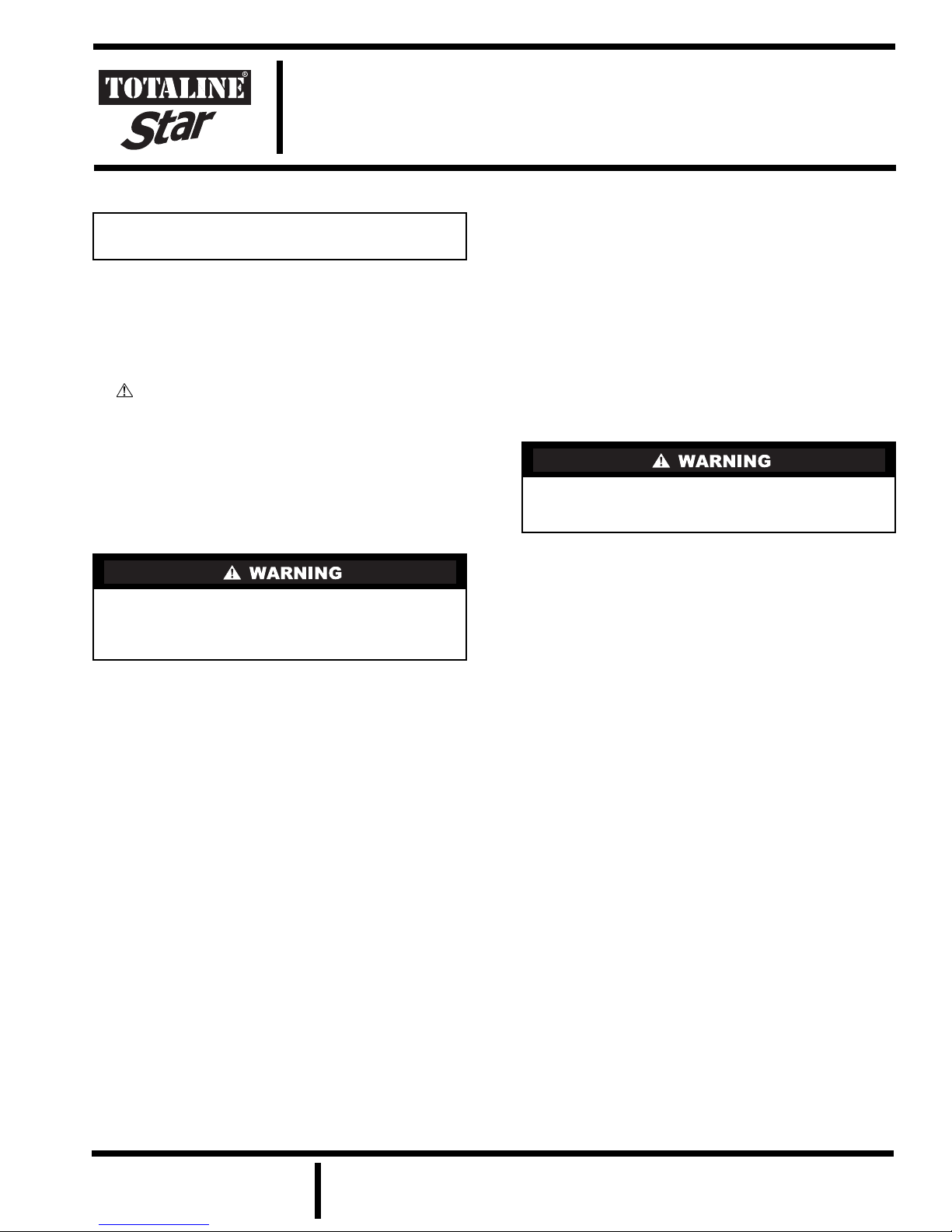
1. Open the electronic air cleaner by lifting the latches on
the side of the frame and opening. See Fig. 1. Inspect
for damage and make sure all the parts are present.
2. Disconnect all power to unit before installation.
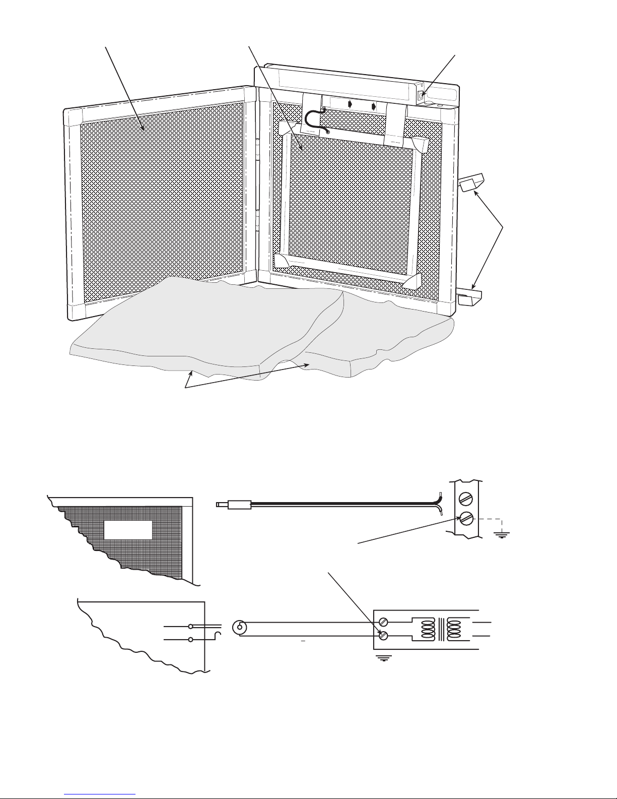
3. Wire electrical power plug to 24 VAC (2 va) power
source (field supplied). Most forced-air heating or
cooling systems have an internal 24 VAC power
source to which the electronic air cleaner can be safely
connected without overloading other circuits. Before
wiring the electronic air cleaner to the power source,
check with a voltmeter that the source does not exceed
30 VAC. See Fig. 2.
The electronic air cleaner is designed to operate at 24 V AC.
Damage or physical injury could result if wired to higher
voltages.
4. Insert the power plug into the port on the electronic air
cleaner. See Fig. 3. If it is necessary to pass the cord
through a hole in the wall of the unit or through an
access door, electrical tape, or the supplied rubber
grommet, should be wrapped around the cord at the
point of entry for protection.
5. Slide the electronic air cleaner into the filter rack of the
air-conditioning equipment or furnace. On a typical
installation, the latches should be facing up and the
power plug should be outside the duct work. See F ig. 4.
OPERATION
The electronic air cleaner operates by removing particles
from the air in two different ways. As the air flows through the
electronic air cleaner, the fiberglass pads filter out most of the
airborne particles. The electrified center screen continues the
process. It helps to remove pollens, allergens, bacteria, dust
mites, smoke, and chemicals from the filtered air.
While the electronic air cleaner is operating, the power supply light will be on. See Fig. 3. If the light does not come on
when power is supplied to the electronic air cleaner, refer to the
Troubleshooting section.
The electronic air cleaner uses litt le power and is on continuously. The system fan can be operated continuously for
increased air circulation through the air cleaner .
Manufacturer reserves the right to
discontinue, or change at any time,
specifications or designs without notice
and without incurring obligations.
REPLACEMENT COMPONENTS DIVISION LITERATURE NUMBER P101-3SI
© CARRIER CORPORATION 2002 11-02 CATALOG NUMBER 570-703
PRINTED IN U.S.A. REPLACES EAC-1SI
OUTSIDE SCREEN CENTER SCREEN POWER SUPPLY
INPUT PORT
LATCHES
FIBERGLASS PADS
ELECTRONIC
AIR CLEANER
ELECTRONIC
AIR CLEANER
Fig. 1 — Electronic Air Cleaner Details
SOLID BLACK
WHITE STRIPE
NOTE: IF ONE TERMINAL
OF POWER SOURCE IS
GROUNDED, HOOK THE
WHITE STRIPED WIRE TO
THIS TERMINAL
SOLID BLACK + (INSIDE)
WHITE STRIPE -- (OUTSIDE)
24 VOLT AC
POWER SOURCE
(FIELD SUPPLIED)
24 VOLTS
AC POWER
SOURCE (FIELD
SUPPLIED)
Fig. 2 — Power Supply Wiring
2
 Loading...