

TOTALINE Signature CPV210 Owner's Manual
OWNER’S
MANUAL
CPV210
Commercial
Non-Programmable
Thermostat
Part Number P374-2100
CONTENTS
Page
GENERAL ...........................................2
CONFIGURATION ....................................3-7
Thermostat Display ...................................3
Heat or Cool Indicator .................................4
Thermostat Front Panel Buttons ........................4
Thermostat Inner Panel Buttons .........................5
OPERATION .........................................7,8
Mode ...............................................7
Two-Stage Operation ..................................7
Electric Heat .........................................7
Dry Contact Switch/External Control .....................7
Remote Temperature Sensor ...........................8
Outdoor Temperature Sensor ...........................8
Manufacturer reserves the right to
discontinue, or change at any time,
specifications or designs without notice
and without incurring obligations.
REPLACEMENTCOMPONENTS DIVISION
R CARRIER CORPORATION 1/98
LITERATURE NUMBER P374-7SO
PRINTED IN CHINA

IMPORTANT: Read entire instructions before configuring the
thermostat.
GENERAL
The commercial, non-programmable thermostats are wall-mounted, lowvoltage thermostats which maintain room temperature by controlling the operation of an HVAC (heating, cooling and ventilation) system. Separate heating and cooling set points and auto-changeover capability allow flexibility.
Dry contacts are provided for optional wiring to field-supplied external output device to control thermostat to occupied and unoccupied set points for
energy savings.
Batteries are not required. During power interruption the internal
NEVERLOST™ memory stores thermostat configuration for an unlimited
time.
IMPORTANT: The thermostat has a security option which can be configured by the installer to limit certain functions of the thermostat such as
changing set points. If the thermostat does not allow modification of these
functions, call the installer to perform desired changes.
2
CONFIGURATION
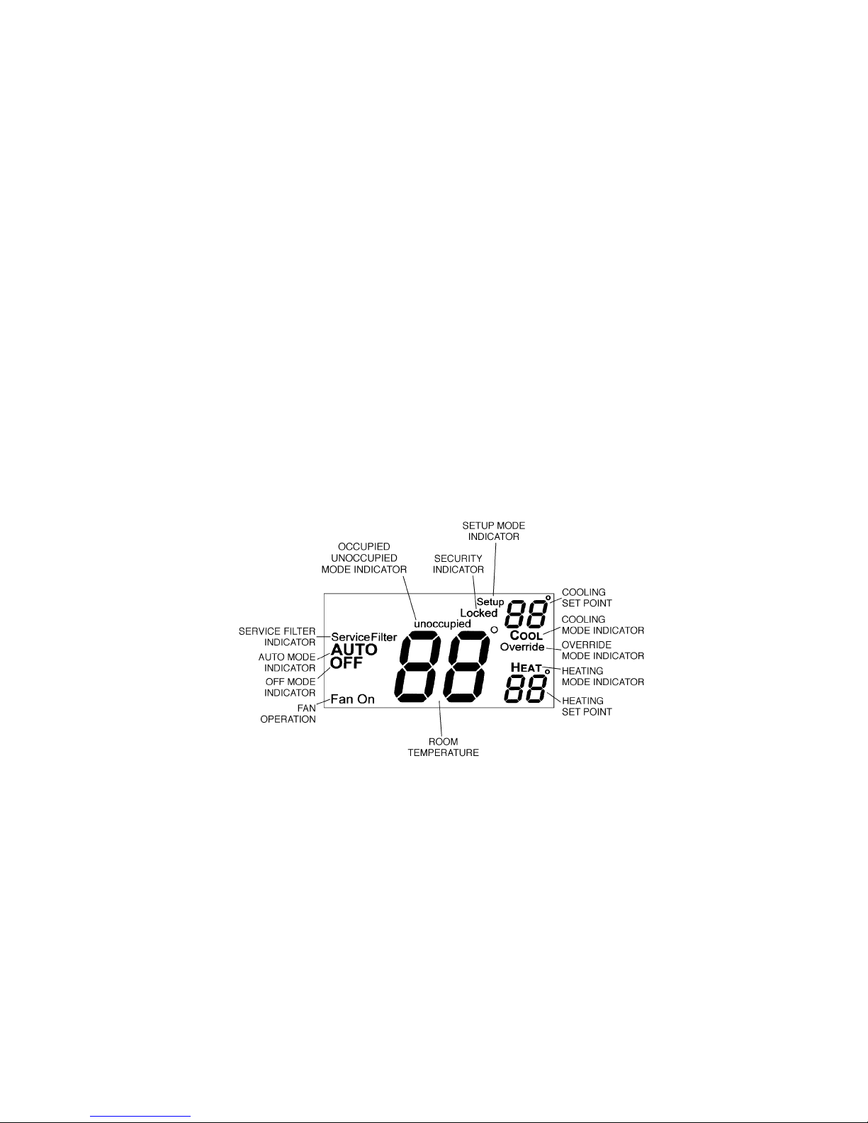
Thermostat Display — The thermostat display is located in the center of
the thermostat. See Fig. 1. The following information can be displayed on the
screen:
• mode (OFF, HEAT, COOL, or AUTO)
• fan setting (FAN ON or blank)
• override indication
• room temperature
• desired temperature
• service filter indicator
• outside temperature
• Occupied or Unoccupied mode (with dry contact connection to external
device)
• setup indicator (configuration mode)
• lock indicator
Fig. 1 — Thermostat Display
3
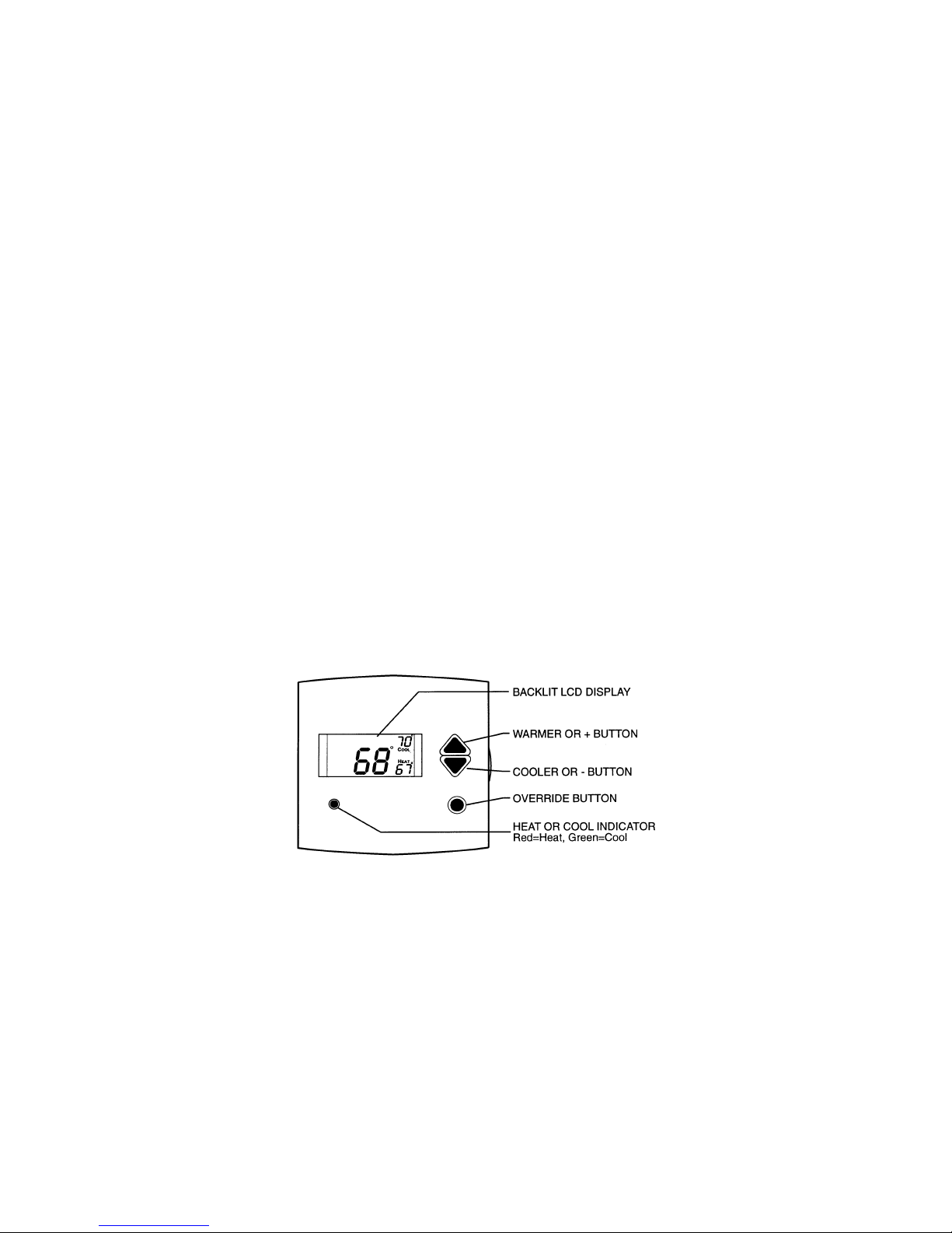
Heat or Cool Indicator — A Heat or Cool indicator is located on the bottom left cover of the thermostat. See Fig. 2. The light will be red if the thermostat is in Heating mode. The light will be green if the thermostat is in
Cooling mode.
Thermostat Front Panel Buttons — The thermostat has buttons on the
front cover which are used to raise or lower the desired set point and override
the current program. See Fig. 2.
SET POINT BUTTONS — The UP ARROW and DOWN ARROW buttons
will raise or lower the current desired temperature set point. If the thermostat
is in AUTO mode, pressing the UP ARROW or DOWN ARROW buttons
will adjust both the heating and cooling set points. Pressing the UP ARROW
or DOWN ARROW buttons in cooling mode will adjust only the cooling set
points. Pressing the UPARROWor DOWN ARROW buttons in heating mode
will adjust only the heating set points. The UP ARROW and DOWN ARROW buttons are also used in programming mode.
OVERRIDE BUTTON — The Override button is used to force the thermostat from Unoccupied mode into the Occupied mode comfort settings when
used with dry contacts and an external device. The Override period will be
set at 30 minutes. The thermostat will then return to Unoccupied mode. To
increase the amount of time in Override mode, press the Override button
Fig. 2 — Thermostat Front Panel Buttons
4
 Loading...