

TOTALINE P707, P707-SHR1504, P707-SHR2004 Installation And Operation Instructions Manual

INSTALLATION
P707
AND OPERATION
INSTRUCTIONS
Part Numbers P707-SHR1504 and 2004
CONTENTS
SAFETY CONSIDERATIONS......................1
GENERAL ........................................1
INSTALLATION ................................ 2-10
Step 1 — Unit Location...........................2
Step 2 — Unit Mounting .......................... 2
Step 3 — Install Drain Line ....................... 3
Step 4 — Locate and Install Weather Hoods......3
Step 5 — Install Ducting To Weather Hood
Location ....................................... 3
Step 6 — Install Indoor Ductwork System ........4
• SUPPLY AIR DUCTING
• EXHAUST AIR DUCTING
• INSTALL DUCTING
• INSTALLATION EXAMPLES
Step 7 — Airflow Balancing ......................6
• AIRFLOW STATION METHOD
• PITOT TUBE BALANCING PROCEDURE
• BALANCING DAMPER ADJUSTMENT
Step 8 — Install Accessories ..................... 9
Step 9 — Electrical Connection to Furnace
(Air Systems Directly Connected to Furnace) .. 9
OPERATION...................................10,11
Winter ...........................................10
Spring...........................................10
Summer......................................... 10
Fall ..............................................10
Modes of Operation ............................. 10
• CONTINUOUS/VENTILATION MODE
• INTERMITTENT/STANDBY MODE
• DEFROST (FAN SHUTDOWN)
MAINTENANCE .................................11
Motor ........................................... 11
Chassis .........................................11
Condensation Panel............................. 11
Drain and Drain Line ............................ 11
Outside Hoods ..................................11
Filters ........................................... 11
Heat Recovery Core ............................. 11
TROUBLESHOOTING............................12
Heat Recovery
Ventilator
Before installation, always check to be sure main power to
systems are OFF. Electrical shock can cause personal
injury or death.
GENERAL
The P707-SHR1504 and P707-SHR2004 Heat Recovery
Ventilators (HRV) are used to exchange indoor stale air with
outside fresh air. The HRV unit is equipped with a special energy recovery core which transfers sensible heat with the fresh
incoming air. The cross-flow design core allows entering and
leaving airstreams to transfer heat energy without mixing.
The HRV is available in 2 sizes with airflow ranges of
150 cfm (SHR1504), and 200 cfm (SHR2004). The design of
this unit is horizontal. Special attention should be given to duct
application, balancing the HRV, and locating unit for easy
access and routine maintenance. See Table 1 and Fig. 1 for
performance data.
AIRFLOW (L/S)
SHR 2004
SHR 1504
120 160
AIRFLOW (CFM)
200 240
300
250
200
150
100
50
0
1.2
0.8
0.6
0.4
0.2
STATIC PRESSURE (IN. WG)
190 38 57 76 94 114
1
0
40080
Fig. 1 — Fan Performance
STATIC PRESSURE (PA)
SAFETY CONSIDERATIONS
Installing, starting up, and servicing ventilation equipment
can be hazardous due to system pressures, electrical components and equipment location (roofs, elevated structures, etc.).
Only trained, qualified installers and service mechanics should
install, start up, and service this equipment.
When working on the equipment, observe precautions in the
literature and on tags, stickers, and labels attached to the
equipment. Follow all safety codes.
Manufacturer reserves the right to
discontinue, or change at any time,
specifications or designs without notice
and without incurring obligations.
Table 1 — Performance Data
UNIT
SHR 1504 72% 69%
SHR 2004 71% 76%
REPLACEMENT CO MPON EN TS DIVI SIO N LITERATURE NUMBER P7 07- 5SI
© CARRIER CORPORATION 2004 4-04 REPLACES: New
PRINTED IN U.S.A. CATALOG NUMBER 570-332
APPARENT SENSIBLE
EFFECTIVENESS
AT 32 F (0° C)
APPARENT SENSIBLE
EFFECTIVENESS
AT –13 F (–24 C)
INSTALLATION
Step 1 — Unit Location —
The HRV must be located
in a heated space where it can be conveniently serviced.
Typically the HRV is located in the mechanical room or an area
close to the outside wall where the weather hoods will be
mounted. If a basement area is not convenient or does not
exist, a utility or laundry room may be used. See Fig. 2 for
dimensions.
Attic installations are not normally recommended due to the
complexity of work to install, freezing conditions in the attic,
and the difficulty of access for service and cleaning.
Connecting appliances to the HRV is not recommended
(such as a clothes dryer, range top, stovetop fan, or central
vacuum system). These appliances may cause lint, dust or
grease to collect in the HRV, damaging the unit.
NOTE: Connecting any of these type of appliances to the
HRV will invalidate the warranty.
Locate the unit close to the outside wall on which the supply
and exhaust hoods will be mounted. There should be a nearby
power supply of 120 volts, 60 Hz available.
There should be access to a water drain for condensate
removal of the unit during defrost.
The unit should be located in a heated area (attic installation
is not recommended). The location should also minimize any
noise level that would be created by the unit in the living area.
Make sure there is adequate access for future maintenance.
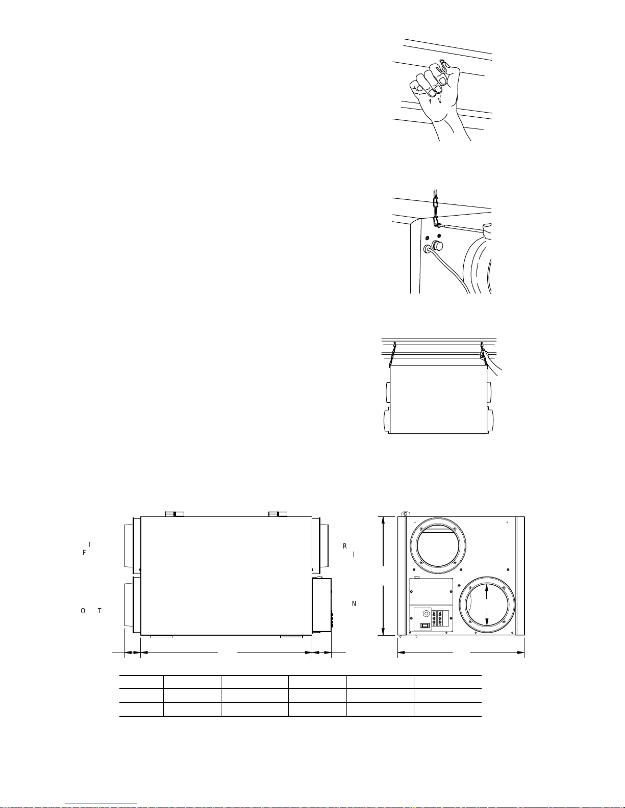
Step 2 — Unit Mounting — The unit is typically hung
from the ceiling for mounting. See Fig. 2 for unit dimensions.
Perform the following to mount the HRV:
1. Place fastening hooks on the strapping board or the
floor joists. See Fig. 3.
3
2. Attach a hanging chain (provided) to each no. 10
bolts (provided) on the top 4 corners of the unit and
tighten. See Fig. 4.
3. Hang the unit by slipping a link onto the hanging
hooks, making sure the unit is level. Unit condensate
will not drain properly unless unit is level. See Fig. 5.
/4-in.
Fig. 3 — Install Fastening Hooks
Fig. 4 — Install Hanging Chain
Fig. 5 — Unit Mounting
OUTDOOR
(FRESH AIR)
EXHAUST
(TO OUTSIDE)
INTAKE
AIR
A
UNITABCD E
SHR 1504
SHR 2004
1
/4″ (56 mm) 231/2″ (596 mm) 25/8″ (67 mm) 173/8″ (441 mm) 161/8″ (413 mm)
2
1
/4″ (56 mm) 277/8″ (707 mm) 25/8″ (67 mm) 173/8″ (441 mm) 201/2″ (520 mm)
2
EXHAUST
AIR FROM
FRESH AIR
BCD
INSIDE
TO INSIDE
E
6"
Fig. 2 — Unit Dimensions
2

Step 3 — Install Drain Line — Through normal op-
eration and during defrost mode, the HRV may produce some
condensation. This water should be directed to flow into a
nearby drain, or be removed by a condensate pump. The HRV
and all condensate lines must be installed in a space where the
temperature is maintained above the freezing point. A P-trap
should be made in the drain line. This will prevent odors from
being drawn back up into the unit.
To install the drain line, install the drain nipple provided.
See Fig. 6.
Install the drain hose onto the drain nipple. Loop the hose to
create a P-trap as shown in Fig. 7. Run the hose to a nearby
drain.
Step 4 — Locate and Install Weather Hoods —
The intake weather hood should be located upstream and at
least 4 to 6 ft away from the exhaust weather hood. The intake
weather hood should be at least 6 ft away from dryer vents and
furnace exhaust (on medium or high efficiency furnaces) and a
minimum of at least 6 ft from driveways, oil fill pipes, gas
meters, or garbage containers.
Locate the hoods at least 18 in. above the ground, or above
the depth of expected snow accumulation. The hoods should be
at least 3 ft from the corner of the building. Do not locate in a
garage, attic or crawl space.
A well designed and installed ducting system will allow the
HRV to operate at its maximum efficiency. Always keep duct
runs as short and straight as possible.
To install the intake and exhaust weather hoods, perform the
following:
1. Using the collar of the outside hood, outline the intake
and exhaust holes to be cut. The hole should be
slightly larger than the collar to allow for the thickness
of the insulated flexible duct. See Fig. 8.
2. Cut a holes using the outline from Step 1. See Fig. 8.
When cutting or drilling holes, be careful not to damage electrical wiring or other hidden objects in wall.
3. Pull the insulated flexible duct through the opening
until it is well extended and straight. Slide the duct
inner vinyl sleeve over the hood collar and secure. See
Fig. 9.
4. Pull the insulation over the duct and then the vapor
barrier over the sleeve and secure with duct tape. See
Fig. 9.
5. Push the hood into the opening. Attach the hood to the
outside wall with mounting screws. See Fig. 10.
6. Using a caulking gun, seal around the hoods to prevent
any leaks. See Fig. 11.
Step 5 — Install Ducting To Weather Hood
Location —
was secured to the intake and exhaust weather hoods in Step 4.
Run the other end of the flexible duct to the HRV installation
location. See Fig. 12.
Clamp the end of the duct to the appropriate port on the
HRV. See Fig. 2.
The insulation should remain full and not be crushed. The
outer liner, which acts as a vapor barrier must be completely
sealed to outer wall and the HRV using tape and/or caulking. A
good bead of high quality caulking (preferably acoustical sealant) will seal the inner flexible duct to both the HRV port and
the weather hood prior to clamping.
To minimize airflow restriction, the flexible insulated duct
that connects the two outside weather hoods to the HRV should
be stretched tightly and be as short as possible. Twisting or
folding the duct will severely restrict airflow.
The inner liner of the flexible insulated duct
Fig. 6 — Install Drain Nipple
Fig. 7 — Install P-Trap
Fig. 8 — Cut Holes for Weather Hoods
Fig. 9 — Install Duct and Sleeve
Fig. 10 — Install Hoods
3
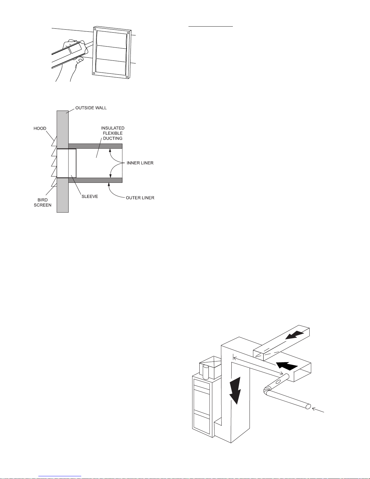
Fig. 11 — Seal Hoods
Fig. 12 — Outdoor Ducting Installation
Step 6 — Install Indoor Ductwork System — To
maximize airflow in the ductwork system, all ducts should be
kept short and have as few bends or elbows as possible. Fortyfive degree elbows are preferred to 90 degree elbows. Use tees
instead of 90 degree elbows whenever possible.
All duct joints must be fastened with screws or duct sealant
and wrapped with a quality duct tape to prevent leakage.
Aluminum foil duct tape is recommended. Galvanized ducting
from the HRV to the living areas in the house is recommended
whenever possible, although flexible duct can be used in
moderation when necessary.
SUPPLY AIR DUCTING — In homes without a forced air
furnace, fresh air should be supplied to all high-usage rooms
including bedrooms and living areas. Air should be supplied
from high wall or ceiling locations. Grilles that diffuse the air
comfortably are recommended. To avoid possible noise transfer
through the ductwork system, a short length (approximately
12 in.) of nonmetallic flexible insulated duct should be connected between the HRV and the supply/exhaust ductwork system.
The main supply and return lines to and from the HRV must
be 6 in. minimum. Branch lines to the individual rooms may
be as small as 4 in., but 5 in. lines are preferred. If floor
installation is the only option available, then special care
should be taken in locating grilles. Installation areas, such as
under baseboard heaters, will help to temper the air. In homes
with a forced air furnace, it may be advisable to connect the
HRV to the furnace ductwork (direct connection).
Building Codes and Combustion Appliance Installation
Codes do not allow location of return air grilles or any opening
such as a breathing tee in an enclosed room with spillage
susceptible combustion appliances.
The fresh air inlet from the HRV must be a minimum
distance of 3 ft from the furnace return drop to ensure proper
air mixing and temperature at the furnace core.
Direct Connection
— A direct connection requires that the
furnace fan run continuously. See Fig. 13. The fan may be
inter-linked electrically (low voltage) with the HRV accessory
control contacts for intermittent demand.
To hard duct the supply air directly into the cold air return of
the furnace, remember to check the airflow balance of the HRV
with the furnace fan both on and off to determine that it does
not imbalance the HRV more than 10%. Make sure that the
minimum distance from the supply air of the HRV to the
furnace is followed. Refer to the local and National Building
and Heating Codes for any variations in these notes.
EXHAUST AIR DUCTING — The stale air exhaust system
is used to draw air from the points in the house where the worst
air quality problems occur. It is recommended that return air
ducts be installed in the bathroom, kitchen, and laundry room.
Additional return air ducts from strategic locations (i.e., greenhouse, atrium, swimming pool, sauna, etc.) may be installed.
The furnace return duct may be also used.
In this method, the exhaust air is not ducted back from
bathrooms, kitchens, etc. to the HRV with dedicated lines.
This method has become popular and provides good
ventilation when installed in accordance with the instructions.
The furnace blower must be running when the HRV is operating for this method to be effective.
INSTALL DUCTING — To install indoor ductwork, perform
the following:
1. Begin with the duct collar on the HRV marked Exhaust
Air In. Slide a short piece (12-in.) of flexible duct over
the duct collar. Using duct tape, tape the flexible duct
to the collar.
2. Run the flexible ducting to the main rigid duct trunk
line, which connects to the remainder of the ducts
going to and from rooms in the house. Repeat the steps
for the Supply Air Out on the side of the HRV.
3. Working from a closet, attic or inside joist wall, run the
length of ducting required for the proper grille location
and cut a hole in the wall.
4. Fasten the mounting collar (field-supplied) to the ducting and fasten the collar to the wall or ceiling with
screws.
5. The field supplied grille may be adjustable. It is recommended that the grilles be completely opened at
first and then adjusted later as needed.
6. Push the grille into the mounting collar or directly into
installed elbow.
FROM HRV
Fig. 13 — Direct Duct Connection
4

INSTALLATION EXAMPLES — It is the responsibility of
the installer to ensure all ductwork is sized and installed as
designed to ensure the system will perform as intended. All air
movement devices have a performance curve. The amount of
air (cfm) that an HRV will deliver is directly related to the total
external static pressure (E.S.P.) of the system. Static pressure is
a measure of resistance imposed on the blower by length of
duct work/number of fittings used in ductwork, duct heater etc.
BEDROOMS
Fully Dedicated System (New Construction)
—Staleairis
drawn from key areas of home (bathroom, kitchen, laundry).
Fresh air is supplied to main living areas. The HRV must be
balanced. See Fig. 14.
Partially Dedicated System
— Stale air drawn from key areas
of home (bathroom, kitchen, laundry) Fresh air supplied to
main living areas via the forced air system. HRV must be balanced. See Fig. 15 and 16.
EXHAUST
BATHROOM
CENTRAL CONTROL
(OPTIONAL)
FRESH AIR TO
LIVING ROOM
FRESH AIR
BEDROOMS
1800 MM
EXHAUST AIR
460 MM
Fig. 14 — Fully Dedicated System
MIXED SUPPLY /
VENTILATION
AIR
HRV
EXHAUST
CENTRAL CONTROL
(OPTIONAL)
BATHROOM
RETURN AIR
THERMOSTAT
SUPPLY
EXHAUST
FURNACE
FRESH AIR
TWO SPEED
FURNACE
EXHAUST AIR
1800 MM
HRV
460 MM
Fig. 15 — Partially Dedicated System
5
HRV CONNECTION
 Loading...