

TOTALINE P474-0401-1RF/REC, P474-0401-1RF, P474-0401-1REC Quick Manual
TOTALINE
WIRELESS REMOTE SENSOR
THE WIRELESS REMOTE SENSOR SYSTEM IS MADE UP OF ONE RECEIVER AND AT LEAST ONE
WIRELESS SENSOR.
!
Up to 8 Wireless Sensors may be used with 1 Receiver. (Unit ID #0 - 7)
!
The Receiver automatically averages all the temperatures it receives
from any and all Wireless Sensors, up to 8 on the same House Code as
the receiver, and reports the average to the thermostat.
!
The Receiver will only ‘listen’ to Wireless Sensors with the same House
Code as the Receiver, and will ‘ignore’ Sensors with different House
Codes than the Receiver.
!
There can be up to 16 Remote Sensor Systems in each installation.
!
If more than 1 Wireless Sensor is used with 1 Receiver, then all Sensors
and the Receiver must have the same House Code for proper operation.
!
If more than 1 Wireless Sensor is used with 1 Receiver, than each
Sensor must have a different Unit ID.
SUGGESTIONS FOR USE OF ONE WIRELESS REMOTE SENSOR:
!
To report the Outdoor Temperature when using a compatible Residential
thermostat. It is recommended to attach the Wireless Sensor to a North
facing wall where it will not be in direct sunlight or the spray of sprinklers.
!
To report the temperature of a room, such as that of a Baby’s room when
using a compatible Residential thermostat.
!
To control to, or to read only, the temperature at the return duct when
using a
!
To control the temperature in a space that is different from where the
compatible Commercial thermostat.
compatible Commercial thermostat is located.
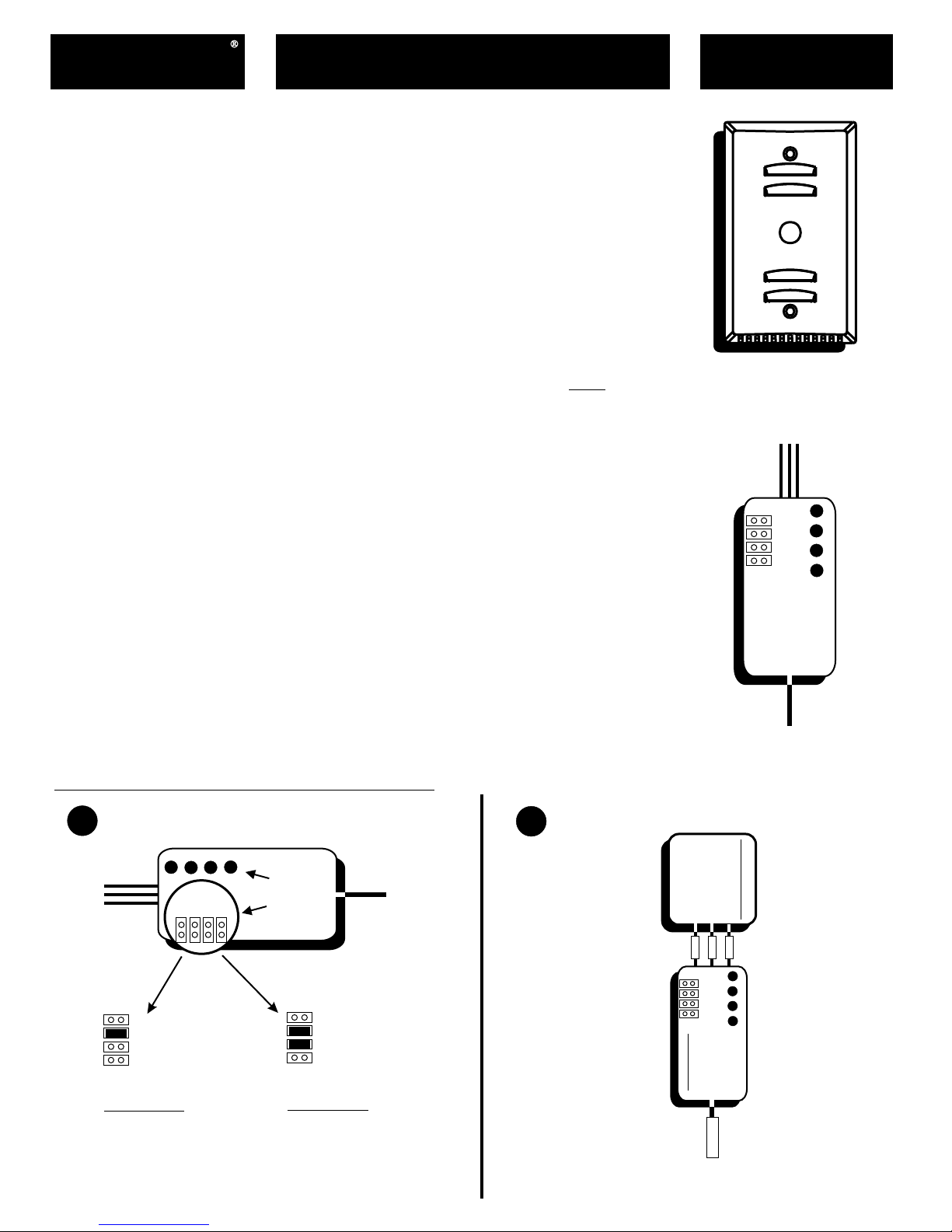
MODEL
P474-0401-1RF/REC
WIRELESS REMOTE SENSOR
with Override button
MODEL P474-0401-1RF
HC1
HC2
HC4
HC8
3
2
1
0
SUGGESTION FOR USE OF MULTIPLE WIRELESS REMOTE SENSORS:
!
To control to an average of more than one Wireless Sensor in a large
open space using a compatible Commercial thermostat. This type of
application would include large, open office areas.
Receiver Setup & Installation
Set the House Code jumpers on the Receiver
1
3
HC1
A
HC1
HC2
HC4
HC8
Example A
House Code
ID = 2
0
1
2
LED’s
HC2
HC4
HC8
Jumper
Location
B
HC1
HC2
HC4
HC8
Example B
House Code
ID = 6
(2 + 4 = 6)
RECEIVER
MODEL P474-0401-1REC
Connect the Receiver to the Thermostat
2
RS GND
BLACK
RECEIVER
HC1
HC2
HC4
HC8
THERMOSTAT
RS+5
RS
WHITE
RED
3
2
1
0
Antenna
The Receiver is put inside the wall behind
the thermostat with the antenna fully extended.
TOTALINE
WIRELESS REMOTE SENSOR
P474-0401-1RF/REC
THE WIRELESS SENSOR CAN TRANSMIT THE TEMPERATURE IN ONE OF FOUR SELECTABLE TIME INTERVALS:
!
Every 5 Seconds.
response is needed. Such as: Remote Duct or Room Sensor applications
!
Every 2 Minutes. This setting is used for Indoor Remote Sensor applications where fast response is
This setting is most useful for Indoor Remote Sensor applications where fast
.
needed. Such as; Remote Duct or Room Sensor applications.
!
Every 5 Minutes. This setting is also used for Indoor Remote Sensor applications under normal
circumstances. Battery life expectancy is approximately 3 years at this setting.
!
Every 10 Minutes. This setting is used for Outdoor Temperature reading for use with Residential
Thermostats. Battery life expectancy is at its longest with this setting.
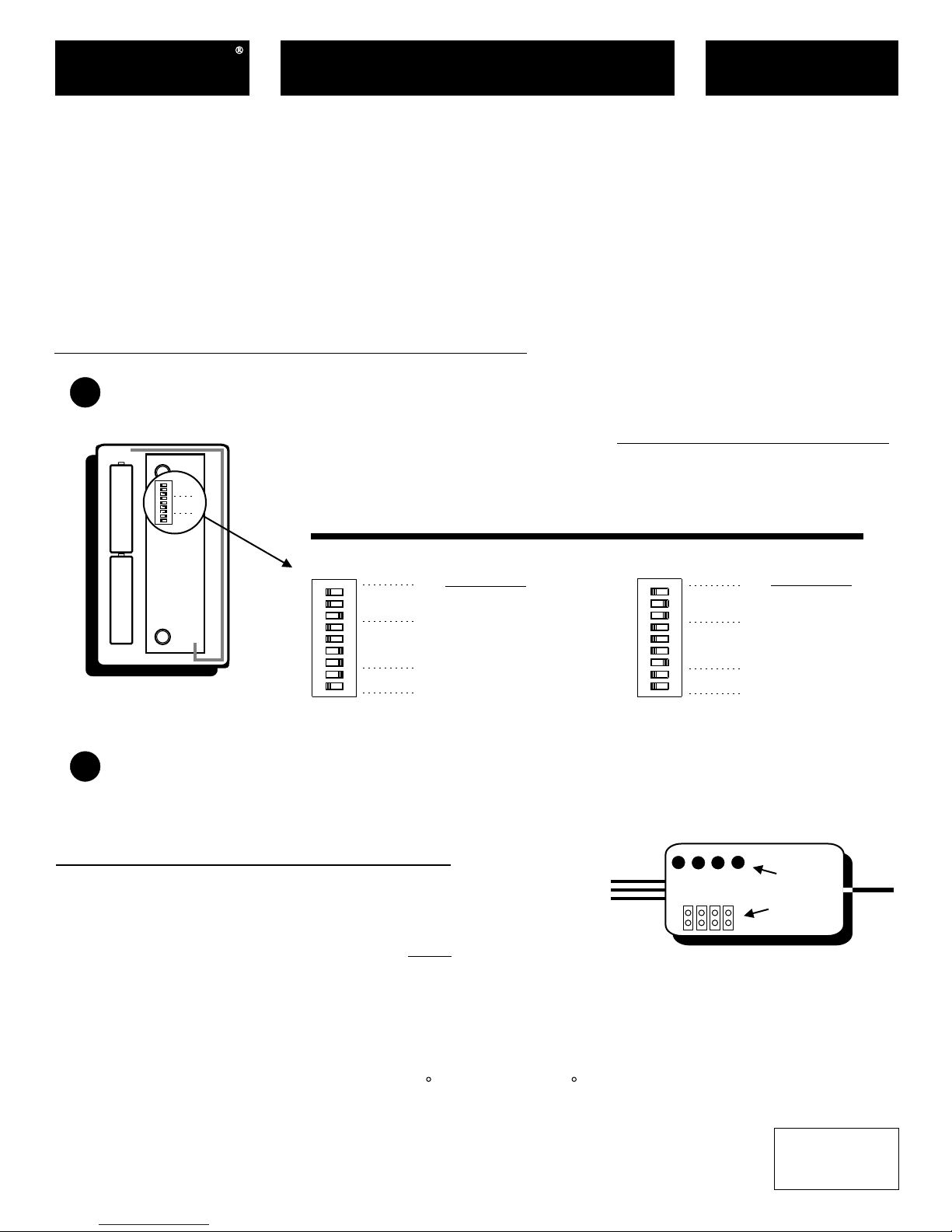
Wireless Sensor Setup & Installation
Set the Switches on the Wireless Sensor
1
MODEL
All Switches in the OFF position = 0.
ADD all switches in the ON position
OFF
ON
44
Unit
Unit
22
ID
ID
11
88
House
House
44
22
Code
Code
11
22
Tx
Tx
11
Interval
Interval
to arrive at the setting.
The House Code must match the
House Code setting on the Receiver.
Transmission Interval (Tx Interval)
0 = 5 Seconds
1 = 2 Minutes
2 = 5 Minutes
3 = 10 Minutes
A B
OFF
WIRELESS REMOTE SENSOR
Switch Location
Attach the Wireless Remote Sensor to the Wall.
2
ON
44
22
Code
Code
11
88
House
House
44
22
Code
Code
11
22
Tx RateTx Rate
11
Unit
Unit
Example A
Unit
ID = 1
House
Code = 3
(1+2 = 3)
Tx
Interval = 5 min.
(2)
Use the supplied screws to secure the Wireless Sensor to the wall.
Care must be taken when installing on to a J-Box to avoid drafts from behind the Sensor.
Troubleshooting & Diagnostics
!
Use only Lithium AA Batteries. Voltage should be 3.1 - 3.6vdc.
!
The Receiver’s antenna must be fully extended for proper operation.
!
Make sure the Receiver & Sensor use the same House Code #.
!
The Receiver has 4 LEDs. The LEDs correspond to Unit ID #0 - 3. When the Receiver receives a valid
temperature from a Wireless Sensor, the corresponding LED will blink and stay on until the next valid
transmission. If a valid transmission is not received within 15 minutes, the LED will turn off.
!
The Receiver can receive and average up to 8 different Unit ID’s on the same House Code, but the LEDs
will only indicate the 1st 4, (#0 - 3). The LEDs are included as a diagnostic tool to confirm reception.
!
Temperature Range of Wireless Sensor is 32 Fahrenheit to 125 Fahrenheit.
OFF
ON
44
22
11
88
44
22
11
22
11
3
HC1
Unit
Unit
Code
Code
House
House
Code
Code
Tx RateTx Rate
1
2
HC2
HC4
0
HC8
Example B
Unit
ID = 3
(1 + 2 = 3)
House
Code = 1
Tx
Interval = 5 sec.
(0)
LED’s
Jumper
Location
This device complies with Part 15 of the FCC Rules. Operation is subject to the following two conditions:
(1) this device may not cause harmful interference, and (2) this device must accept any
interference received, including interference that may cause undesired operation.
Replacement Components Division - Carrier Corporation - 02/04 - Patents Pending P/N 88-140 Rev. 2
FCC ID: MUHRSTX
RF Sensor P474-0401-1RF/REC
Tested to Comply
c
with FCC Standards
C
F
FOR HOME OR OFFICE USE
 Loading...