

TOTALINE P286-1500 Instruction Manual
FCC Statement THIS DEVICE COMPLIES WITH PART 15 OF THE FCC
RULES. OPERATION IS SUBJECT TO THE FOLLOWING TWO CONDITIONS:
(1) THIS DEVICE MAY NOT CAUSE HARMFUL INTERFERENCE, AND (2)
THIS DEVICE MUST ACCEPT ANY INTERFERENCE RECEIVED, INCLUDING
INTERFERENCE THAT MAY CAUSE UNDESIRED OPERATION.
REPLACEMENT COMPONENTS DIVISION©CARRIER CORPORATION
www.totaltouch.info
Technical Support: 1-866-90TOUCH (1-866-908-6824)
Physical Dimensions
Case: 5.75” x 4.75” x 1.25” (145mm x 120mm x 30mm)
Display: 3.625” x 2.125” (95mm x 55mm)
Electrical Rating
24 volt AC/DC
Class 2 maximum 4 amps
Temperature Accuracy +/-1°F degree
Power failure protection safeguards clock and memory.
Made in China / Printed in China
US PatentS 7,050,026 | 7,028,912 | 6,902,117 | 6,786,421 Other Patents Pending
www.totaltouch.info
Technical Support 1-866-90TOUCH (1-866-908-6824)
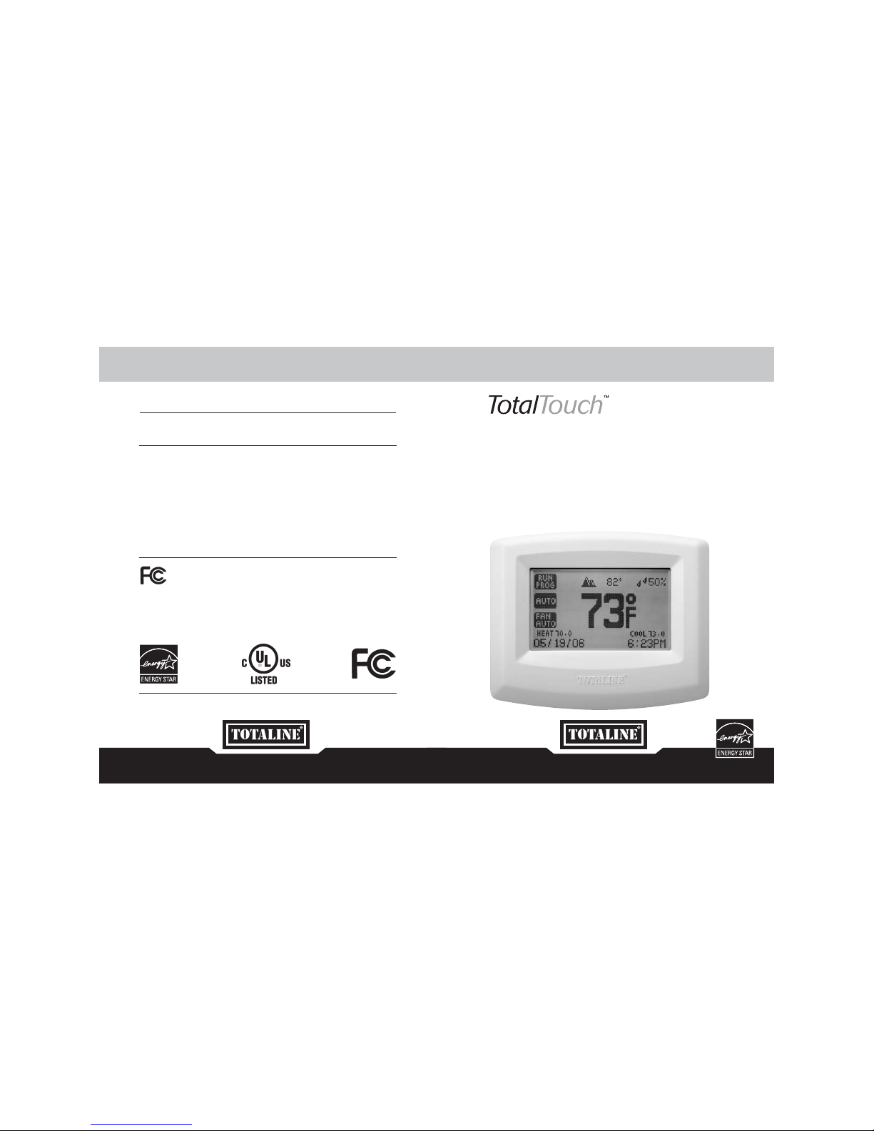
INSTRUCTION MANUAL
P286-1500 3 Heating and 2 Cooling
with Automatic Humidity Control & Dual Fuel Switch
To be used with P286-0001: Outdoor Wireless
Temperature Transmitter & Receiver Kit
INTRODUCING THE P286-1500 Featuring automatic humidity controller
and fossil fuel switch which is only activated when combined with our
Outdoor Wireless Transmitter and Receiver Kit. (P286-0001)
Standard in all TotalTouch™ Thermostats Complete and quick set-up with gas,
oil, electric, heat pump, air conditioning and multi-stage HVAC systems.
• 7 Day programmable with 4 events
per day – including fan
• Large, easy to read dot matrix display
• True touch screen technology
• Automatic selection of cool
or heat mode
• Programmable fan mode
• Programmable filter monitor
• Programmable installer message
• Configurable humidification relay
• Independent de-humidification relay
• Customizable full and partial
lock security
• Adjustable differential settings
for multistage installations
• Energy watch calculates kWh
and HVAC costs
• Simple mode for
non-programmable usage
• Programmable Vacation Mode
Complete Comfort
3
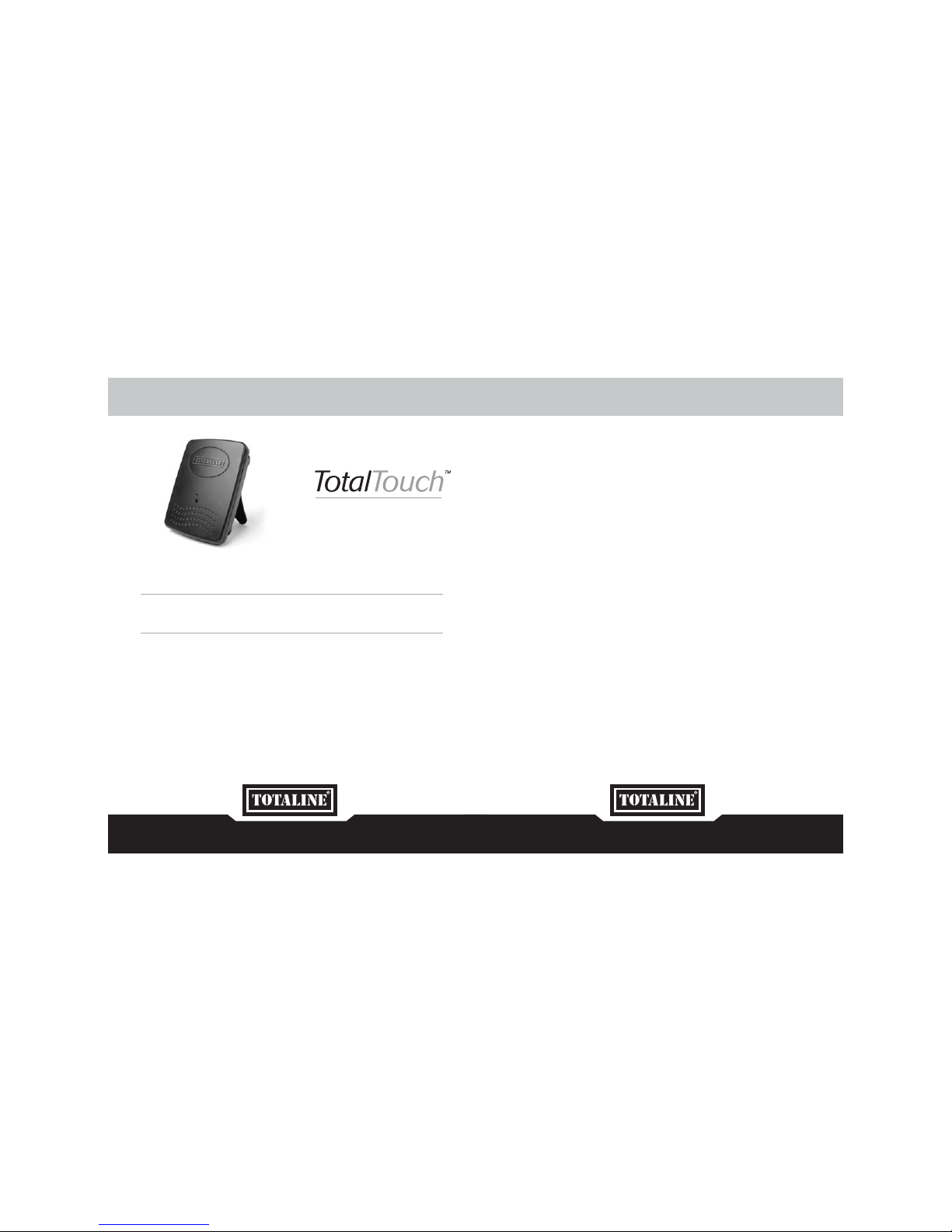
TABLE OF CONTENTS
Glossary of Terms...................................................................................................6
Installing your Thermostat .......................................................................................8
Wiring Table and Diagrams .............................................................................9 – 21
Welcome to the Home Page.................................................................................22
Control Page – Temperature Operation Mode & Temperature Setpoints .......23 – 25
Automatic Humidity, Humidification & De-humidification Setpoints ...............26 – 28
Fan Operation Mode.............................................................................................29
Programming your Thermostat......................................................................30 – 36
Menu Page ..........................................................................................................30
Date and Time Settings ........................................................................................31
Program Settings ..................................................................................................32
Energy Watch .......................................................................................................33
Screen Options.....................................................................................................34
Vacation Mode......................................................................................................35
Filter Monitor.........................................................................................................36
Advanced Features ...............................................................................................37
Advanced Features – Entry Page..................................................................38 – 39
Configuring your Equipment..................................................................................40
Duel Fuel Switch ...................................................................................................41
Setting the Differential ...........................................................................................42
Timer Feature........................................................................................................43
Heat Pump ...........................................................................................................44
Humidification and De-humidification ............................................................45 – 47
Temperature and Humidity Calibration...........................................................48 – 49
Simple Thermostat Mode......................................................................................50
Troubleshooting ............................................................................................51 – 52
Warranty ......................................................................................................54 – 55
Your Kit Includes: Outdoor Wireless Temperature Transmitter
+ Antenna + Receiver Module + 2 Batteries
This convenient feature provides you the outdoor temperature right
on your TotalTouch™ thermostat.
INTRODUCING THE P286-0001
Outdoor Wireless Temperature Transmitter and Receiver Kit
Complete Comfort
54
Anticipator control – Anticipator control
is used to turn off the heating equipment
before the room temperature actually
reaches the cut-out point.
Cut-in Point – The air temperature at the
thermostat at which it initiates action of
heating/cooling equipment.
Cut-out Point – The air temperature at the
thermostat at which it terminates action of
heating/cooling equipment.
Cycle rate – Cycle rate is the frequency that
heating or cooling equipment is turned on
during a certain period of time. Cycle rate
is often given in units of cycles per hour (CPH).
Dehumidify – The process of removing
moisture from the air.
Dehumidifier – Device used to remove
moisture from the air.
Differential – Differential is defined as
the difference between the cut-in and
cut-out points as measured at the
thermostat under specified operating
conditions. For example, if the thermostat
turns the heating equipment on at 70
degrees F and turns the heating equipment
off at 74 degrees F, then the differential is
4 degrees F.
Humidifier – A device used to add
moisture to a space.
Humidistat – A control which is operates
the humidifier and is affected by changing
humidity.
Humidity – Moisture in the air.
Programmable thermostat – A thermostat
with the capability of automatically adjusting
temperature set point to pre-selected
settings at pre-selected times.
Setback – The automatic alteration of the
thermostat control point(s) by means other
than manually changing the temperature set
point.
Set point – The desired temperature
setting on an electromechanical or
electronic thermostat.
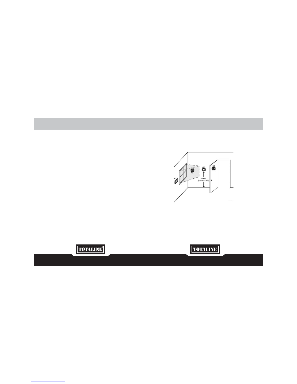
GLOSSARY OF TERMS SELECT A LOCATION
Install your TotalTouch™ thermostat approximately 5 feet (1.5 meters) above the floor in
an area with good air circulation.
Avoid the following locations:
• Hot or cold air from ducts
• Radiant heat for appliances or sun such as a skylight
• Unheated areas or uncooled areas:
for example an outside wall behind the thermostat.
6 7
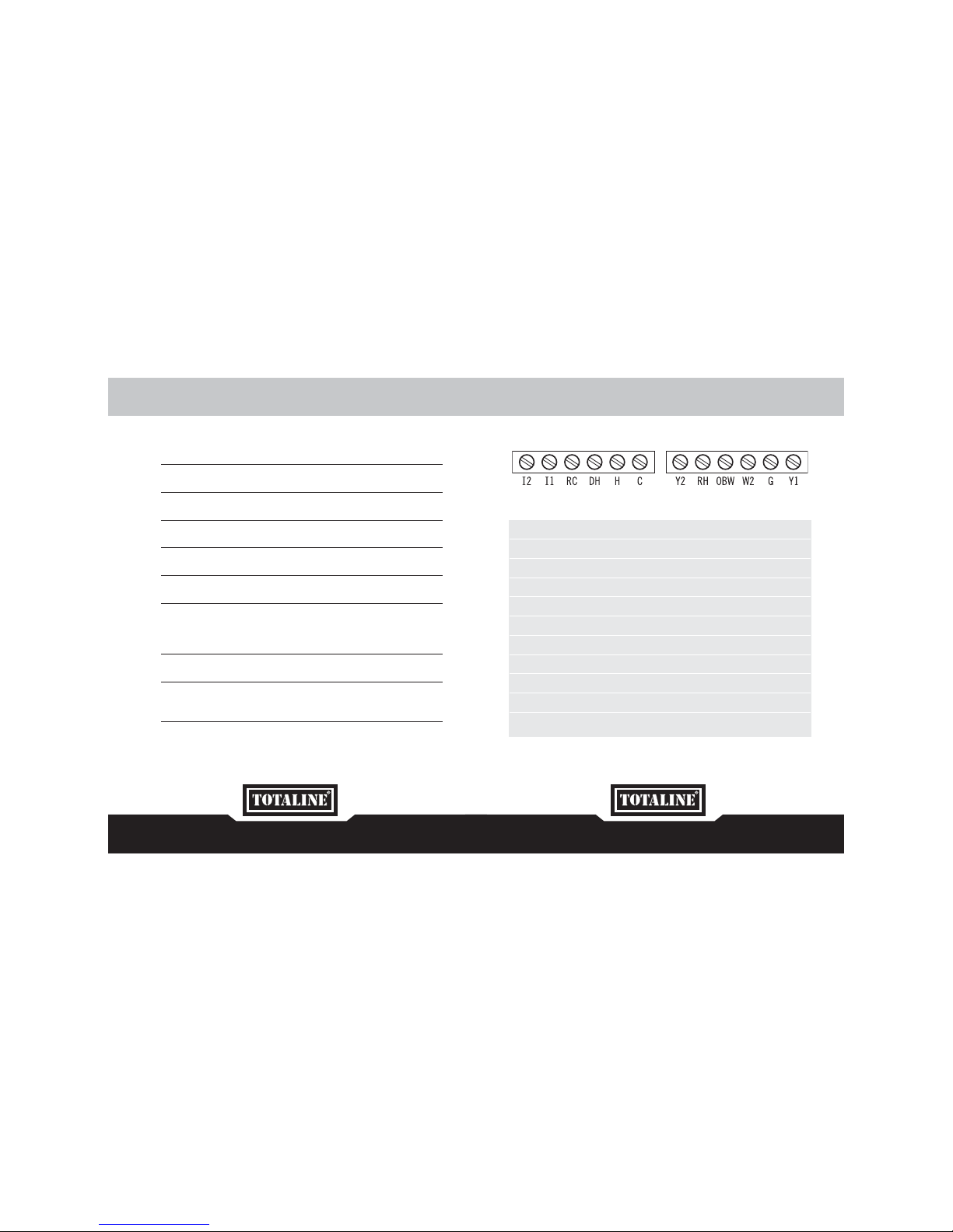
WIRING LEGEND
TERMINAL EQUIPMENT STANDARD COLOR
Y1 First Heat Pump & AC Yellow
G Fan Green
W2 First Stage Furnace White
OBW Reverse Valve - Second Stage Furnace Orange
RH 24v Red
Y2 Second Heat Pump & AC Unknown
C Common Blue
H Humidity Control Unknown
DH Dehumidity Control, Variable Fan Control Unknown
RC 24v Unknown
11 & 12 Not Used
NOTE: The above colors are standard in HVAC industry. The wiring should be
confirmed before installation
MOUNTING TOTALTOUCH™ TO THE WALL
1. Make sure to turn off the power supply located at the electrical service panel.
All heating and cooling units should be OFF.
2. Remove the cover plate by pulling up the cover from the left or right side only.
3. Align the thermostat unit to the wall.
4. Mark the two locations for drilling the 3/16” holes required for the plastic screw anchors.
5. Remove the thermostat and drill the two 3/16” holes in these locations.
6. Insert the plastic gyproc screw anchors and tighten them securely.
7. Make the appropriate wire connections based on the specifications of the
household HVAC unit(s). Please refer to Wiring Table to determine the appropriate
wire connections.
8. Securely mount the thermostat unit to the wall with the two supplied screws.
9. Fit the cover plate back by clipping one side first (left or right) and than push down
on the opposite side.
10. Turn on the electricity at the electrical service panel.
8 9

WIRING TABLEWIRING TABLE
Cooling Only Air Conditioner / Furnace Off
Y1 Y2 W2 OB/W R/C R/H G
AC x x x
2 Air Conditioner / Furnace Off
Y1 Y2 W2 OB/W R/C R/H G
AC1 AC2 x x x
Heating Only No Compressor / El. Furnace
Y1 Y2 W2 OB/W R/C R/H G
El. Furn El. Furn 2* x x x
No Compressor / Emergency El. Furnace
Y1 Y2 W2 OB/W R/C R/H G
Emg. El. Furn El. Furn El. Furn 2* x x x
No Compressor / Gas
Y1 Y2 W2 OB/W R/C R/H G
Gas Gas 2* x x x
No Compressor / Oil
Y1 Y2 W2 OB/W R/C R/H G
Oil Oil 2* x x x
Heating Only No Compressor / 2 Stage Gas
Y1 Y2 W2 OB/W R/C R/H G
Gas 1 Gas 2 x x x
* if there is another furnace, then connect it to OB/W relay.
1 Stage Cooling, 1 Stage Heating Heat Pump / Furnace Off
Y1 Y2 W2 OB/W R/C R/H G
HP OB x x x
Air Conditioner / El. Furnace
Y1 Y2 W2 OB/W R/C R/H G
AC El. Furn x x x
Air Conditioner / Emergency El. Furnace
Y1 Y2 W2 OB/W R/C R/H G
AC Emg. El. Furn El. Furn x x x
Air Conditioner / Gas
Y1 Y2 W2 OB/W R/C R/H G
AC Gas x x x
Air Conditioner / Oil
Y1 Y2 W2 OB/W R/C R/H G
AC Oil x x x
10 11

WIRING TABLEWIRING TABLE
1 Stage Cooling, 2 Stage Heating Air Conditioner / 2 Stage Heating
Y1 Y2 W2 OB/W R/C R/H G
AC Gas 1 Gas 2 x x x
Air Conditioner / El. Furnace
Y1 Y2 W2 OB/W R/C R/H G
AC El. Furn 1 El. Furn 2 x x x
Air Conditioner / Emergency El. Furnace
Y1 Y2 W2 OB/W R/C R/H G
AC Emg. El. Furn El. Furn 1 El. Furn 2 x x x
Air Conditioner / Gas
Y1 Y2 W2 OB/W R/C R/H G
AC Gas 1 Gas 2 x x x
Air Conditioner / Oil
Y1 Y2 W2 OB/W R/C R/H G
AC Oil 1 Oil 2 x x x
Heat Pump / El. Furnace
Y1 Y2 W2 OB/W R/C R/H G
HP El. Furn OB x x x
1 Stage Cooling, 2 Stage Heating Heat Pump / Gas
Y1 Y2 W2 OB/W R/C R/H G
HP Gas OB x x x
Heat Pump / Oil
Y1 Y2 W2 OB/W R/C R/H G
HP Oil OB x x x
1 Stage Cooling, 3 Stage Heating Heat Pump / 2 Stage Gas
Y1 Y2 W2 OB/W R/C R/H G
HP Gas 2 Gas 1 OB x x x
2 Stage Cooling, 1 Stage Heating HP/AC / Furnace Off
Y1 Y2 W2 OB/W R/C R/H G
HP AC OB x x x
2 Air Conditioner / El. Furnace
Y1 Y2 W2 OB/W R/C R/H G
AC 1 AC 2 El. Furn x x x
2 Air Conditioner / Gas
Y1 Y2 W2 OB/W R/C R/H G
AC 1 AC 2 Gas x x x
12 13

2 Stage Cooling, 1 Stage Heating 2 Air Conditioner / Oil
Y1 Y2 W2 OB/W R/C R/H G
AC 1 AC 2 Oil x x x
2 Stage Cooling, 2 Stage Heating HP/AC / El. Furnace
Y1 Y2 W2 OB/W R/C R/H G
HP AC El. Furn OB x x x
HP/AC / Gas
Y1 Y2 W2 OB/W R/C R/H G
HP AC Gas OB x x x
HP/AC / Oil
Y1 Y2 W2 OB/W R/C R/H G
HP AC Oil OB x x x
2 Heat Pump / Furnace Off
Y1 Y2 W2 OB/W R/C R/H G
HP 1 HP 2 OB x x x
2 Air Conditioner / El. Furnace
Y1 Y2 W2 OB/W R/C R/H G
AC 1 AC 2 El. Furn 1 El. Furn 2 x x x
2 Stage Cooling, 2 Stage Heating 2 Air Conditioner / Gas
Y1 Y2 W2 OB/W R/C R/H G
AC 1 AC 2 Gas 1 Gas 2 x x x
2 Air Conditioner / Oil
Y1 Y2 W2 OB/W R/C R/H G
AC 1 AC 2 Oil 1 Oil 2 x x x
2 Air Conditioner / 2 Stage Gas
Y1 Y2 W2 OB/W R/C R/H G
AC 1 AC 2 Gas 1 Gas 2 x x x
2 Stage Cooling, 3 Stage Heating 2 Heat Pump / Gas
Y1 Y2 W2 OB/W R/C R/H G
HP 1 HP 2 Gas OB x x x
2 Heat Pump / Oil
Y1 Y2 W2 OB/W R/C R/H G
HP 1 HP 2 Oil OB x x x
2 Heat Pump / El. Furnace
Y1 Y2 W2 OB/W R/C R/H G
HP 1 HP 2 El. Furn OB x x x
WIRING TABLEWIRING TABLE
14 15
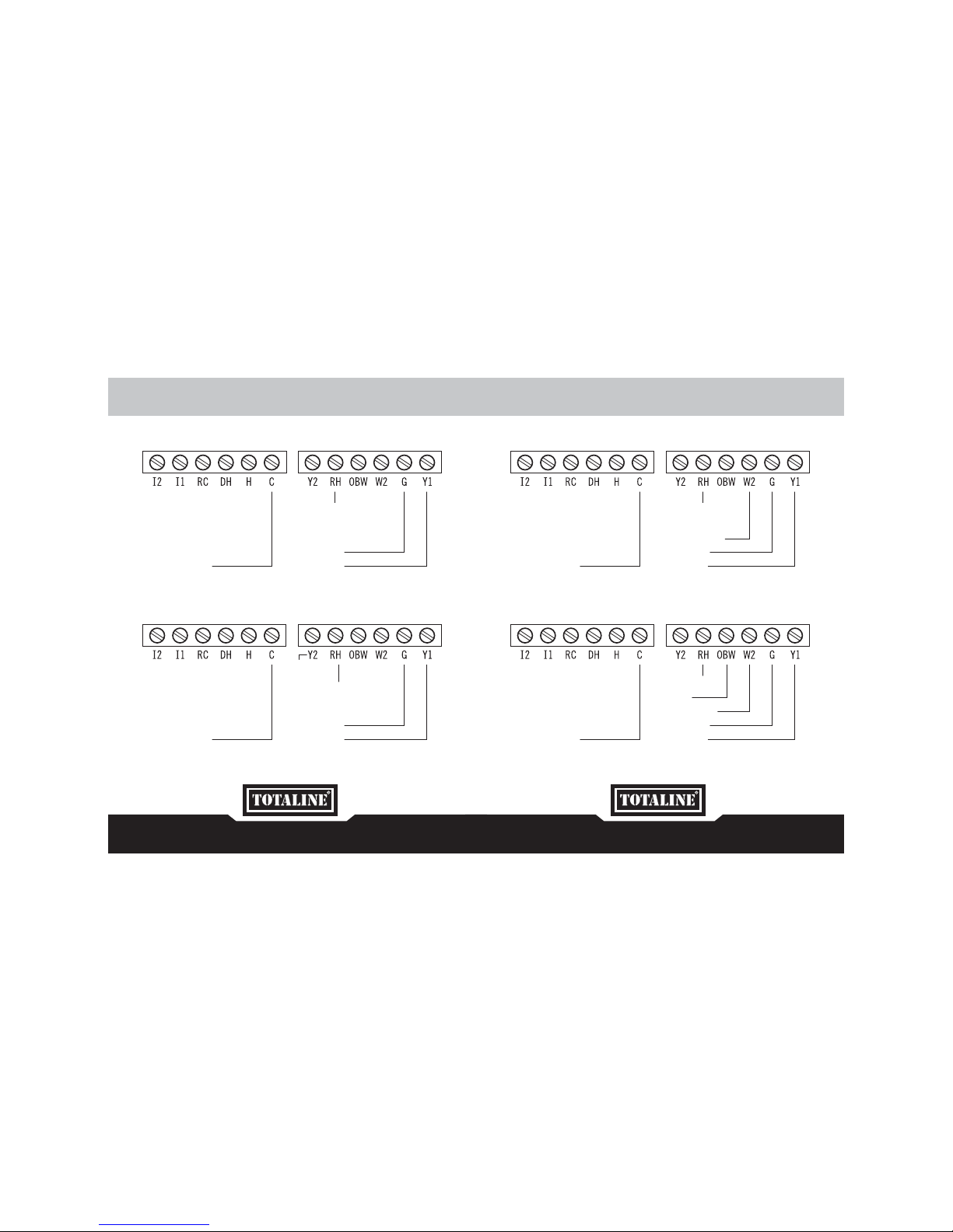
WIRING DIAGRAM
AC & TWO HEAT
24V (RED)
Heat2
Heat1 (WHT)
Fan (GRN)
AC (YLW)
COMMON (BLUE)
AC & ONE HEAT
24V (RED)
Heat (WHT)
Fan (GRN)
AC (YLW)
COMMON (BLUE)
TWO AC
AC2 (YLW)
24V (RED)
Fan (GRN)
AC1 (YLW)
COMMON (BLUE)
WIRING DIAGRAM
ONE AC
24V (RED)
Fan (GRN)
AC (YLW)
COMMON (BLUE)
16 17
 Loading...