

TOTALINE P130-1224C, P130-1430C, P130-1424C, P130-1425C, P130-1520C Installation, Operation And Maintenance Instructions
...
INSTALLATION,
OPERATION, AND
MAINTENANCE
INSTRUCTIONS
1300 Series
Electronic Air Cleaner
IMPORTANT: Read entire instructions before
installing the electronic air cleaner.
IF YOU NEED HELP call toll free: 1-800-565-5326
CONTENTS
SAFETY CONSIDERATIONS
PACKAGE USAGE
GENERAL
. . . . . . . . . . . . . . . . . . . . . . . . . . . . . . . . . . . . . . . . 1
COMPONENTS
. . . . . . . . . . . . . . . . . . . . . . . . . . . . . . . . 1
. . . . . . . . . . . . . . . . . . . . . . . . . . . . . . . . . . . 2
Frames with Outer Screens
Collecting Pads
Charging Bar
. . . . . . . . . . . . . . . . . . . . . . . . . . . . . . . . . . 2
. . . . . . . . . . . . . . . . . . . . . . . . . . . . . . . . . . . . . 2
High Voltage Power Supply Box
INSTALLATION
Location
. . . . . . . . . . . . . . . . . . . . . . . . . . . . . . . . . .2,3
. . . . . . . . . . . . . . . . . . . . . . . . . . . . . . . . . . . . . . . . . 2
Electronic Air Cleaner Installation
OPERATION
MAINTENANCE
. . . . . . . . . . . . . . . . . . . . . . . . . . . . . . . . . . . . . . 3
. . . . . . . . . . . . . . . . . . . . . . . . . . . . . . . . 3-5
Collecting Pad Replacement
TROUBLESHOOTING
. . . . . . . . . . . . . . . . . . . . . . . . . . . . . 5
. . . . . . . . . . . . . . . . . . . . . . 1
. . . . . . . . . . . . . . . . . . . . . . 2
. . . . . . . . . . . . . . . . . . 2
. . . . . . . . . . . . . . . . 3
. . . . . . . . . . . . . . . . . . . . . 3
SAFETY CONSIDERATIONS
Read and follow manufacturer instructions carefully. Im-
proper installation may damage media air cleaner.
Recognize safety information. This is the safety alert
symbol . When the safety alert symbol is present on equipment or in the instruction manual, be alert to the potential for
personal injury.
Understand the sig nal words DANGER, WARNING, and
CAUTION. These words are used with the safety alert symbol.
DANGER identifies the most se rious hazards which will re sul t
in severe personal injury or death. WA RNING signifies a haz ard which could result in personal injury or death. CAUTION
is used to identify unsafe practices which would result in minor
personal injury or property damage.
Before beginning any installation or modification, be certain that the main line electrical disconnect switch is in the
OFF position. Electric shock could result. Tag disconnect
switch with suitabl e warn ing labe ls.
Installation and servicing of air-conditioning equipment can
be hazardous due to system pressure and electrical components. Only trained and qualified service personnel should
install, repair, or service air-conditioning equipment.
Untrained personnel can perform the basic maintenance
functions of replacing collecting pads. All other operations
should be performed by trained service personnel. When working on air-conditioning equipment, observe precautions in the
literature, tags and labels attached to the unit, and other safety
precautions that may apply.
Follow all safety codes. Wear safety glasses and work
gloves.
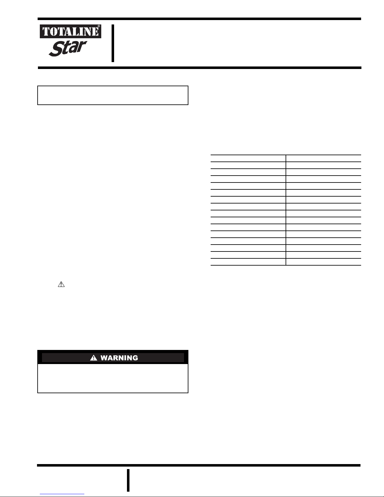
PACKAGE USAGE
PART NUMBER SIZE (in.)
P130-1224C
P130-1424C
P130-1425C
P130-1430C
P130-1520C
P130-1620C
P130-1624C
P130-1625C
P130-1820C
P130-2020C
P130-2024C
P130-2025C
P130-2424C
P130-2425C
P130-2430C
12 x 24
14 x 24
14 x 25
14 x 30
15 x 20
16 x 20
16 x 24
16 x 25
18 x 20
20 x 20
20 x 24
20 x 25
24 x 24
24 x 25
24 x 30
GENERAL
The electronic air cleaner is designed to remove atmospheric and household dust, pollen, mold spores, bacteria, fungi,
insecticide dust, animal dander, coal dust, mites, cooking
smoke and grease, tobacco smoke, and other particles down to
sub-micron levels.
The electronic air cleaner is installed in the furnace fi lter
rack where a filter would nor mally be pl ace d. It is designed t o
be installed in a 1-in. filter track. Many sizes are available to fit
in different size air ducts.
Airborne pollutants are carried through the return air ducts
of the heating/cooling system to the elec tronic a ir cleaner. The
collecting pads of the electronic air cl eaner utilize electronic
polarization and ionization to create high filtration efficiencies.
The particles are captured by the collecting pads. The 1-in.
design protects HVAC equipment and their energy efficiencies
due to the electronic air cleaner’s low static pressure.
Regular maintenance (replacement or cleaning of collecting
pads) is required by the home owner.
Manufacturer reserves the right to
discontinue, or change at any time,
specifications or designs without notice
and without incurring obligations.
REPLACEMENT COMPONENTS DIVISION
© CARRIER CORPORATION 2001 12/01 LITERATURE NUMBER P103-4SI
PRINTED IN U.S.A. CATALOG NUMBER 570-470

COMPONENTS
See Fig. 1 for a description of the electronic air cleaner.
Frames with Outer Screens —
up of two sides. An optional key is supplied with the frame and
may be used to lock and unlock the corner fasteners. The key is
located over the top of the outlet and LED lights. The outer
screens may be vacuumed or washed when dirty.
Collecting Pads —
the air. One of the collecting pads will contain carbon fibers
which are used to ionize and polarize the pads. The pads cannot
be washed or vacuumed and must be replaced when dirty.
Charging Bar —
the collecting pad with the carbon fibers and must be in contact
with the carbon fibers on the pad. The charging bar is energized
by the high voltage power supply box.
The collecting pads are used to filter
The charging bar is laid across the top of
High Voltage Power Supply Box —
age power supply box provides power to the electronic air
cleaner. A 24-V supply cord and jack is provided for wiring to
a 24-V power source.
The frame is made
The high volt-
INSTALLATION
Location —
cleaner should be installed in t he filter rack. Note the dimensions of the filter rack and order the appropriate sized electronic air cleaner to fit the rack.
If a filter rack does not exist, then the el ectronic air cleane r
must be installed in the return air duct, as close to the blower
compartment as possible. This location provides the most even
airflow across the collection pads and allow s the electr onic air
cleaner to keep the system motor and blower clean. When
choosing location, there must be adequate room to remove the
electronic air cleaner. It is best to use the largest possible electronic air cleaner size for installation.
Be sure to allow room for routing the 24-V power wiring to
a 24-VAC power source.
NOTE: Be sure to notify home owner not to install any device
within 3 ft from the side of the electronic air cleaner after
installation is complete. Regular servicing of the electronic ai r
cleaner is required. A 3-ft clearance is required to remove electronic air cleaner and collection pads for maintenance or
replacement.
If a filter rack exists, then the electronic air
HIGHBOY FURNACE — The fil ter rack i s nor mall y loc ated
in the return air duct.
LOW BO Y FU RN AC E — The filter rack is normally located
in the blower compartment section. Remove the blower compartment door to view filter rack.
ELECTRIC FURNACE — The filter rack is normally
located in the bottom furnace section, located horizontally
above the filter box.
LOWBOY FURNACE (O IL) — The filter rack is normally
located in the blower compartment section. Remove the
blower compartment door to view filter rack. Some older furnaces are equipped with two racks, an upper horizontal and a
lower diagonal. The air cleaner would be placed in the lower
diagonal filter rack.
HORIZONTAL FURNACE — The filter rack is normally
located in the return air duct.
FULL SIZE EXISTING ELECTRONIC AIR CLEANER —
If the new electronic air cleaner is replacing an existing full
size air cleaner, be sure to turn off the existing air cleaner
before removal.
INSTALLATION LOCATION WITH HUMIDIFIER — If
a separate humidifier is purchased, it should be installed in the
furnace warm air duct. However, a humidifier may be installed
in the return air duct without causing problems to the electronic
air cleaner. Care must be taken to ensure that the humidifier
does not leak, as this may cause damage to the electronic air
cleaner and mineral deposits on the air cleaner.
Wet collection pads may cause arcing or shorts on the electronic air cleaner. Wet collecti on pads may also decrease electronic air cleaner efficiency.
NOTE: An atomizing-type humidifier should only be installed
downstream of the electronic air cleaner. If the atomizing-type
humidifier is installed upstream, high humidity, salts, and minerals may damage the electronic ai r cleaner and cause servic e
problems. If the atomizing-type humidifier must be installed
upstream, the atomizing-type humidifier must be installed as
far from the electro nic air cl eaner as po ssible.
INSTALLATION LOCATION WITH AIR CONDITIONER — Whenever possible, the electronic air cleaner
should be installed upstream of the cooling coil. This location
will clean the air before it reaches the evaporator coil.
Fig. 1 — Electronic Air Screen Components
2
Electronic Air Cleaner Installation —
Perform the
following to install the electronic air cleaner.
1. If a filter rack exists, remove the ex isting f urnace f ilter.
Thoroughly clean the blower compartment and ductwork where the electronic air cleaner is to be installed.
If a filter rack does not exist, fabricate a filter rack
using the location information provided in the Location section on this page.
2. Place electronic air cleaner in filter rack. Ensure that
there is no air leakage.
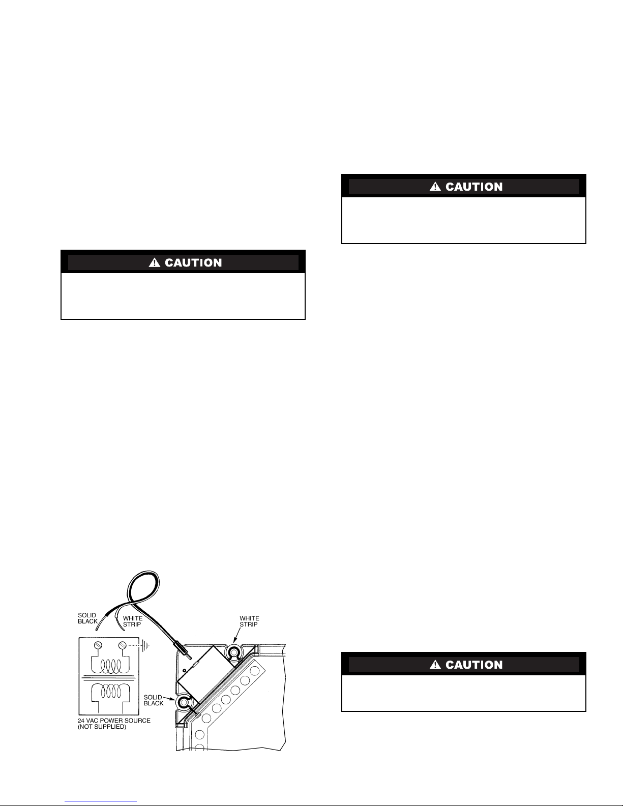
3. Wire the power cord to a 24-V power source. See
Fig. 2. Use a voltmeter to positively identify that the
power source is a 24-V (maximum 30-V) source. A
field-supplied 110-V to 24-V adapter or transformer
may be used to provide 24-V power. Ensure that the
electronic air cleaner is properly grounded.
NOTE: If one terminal of the power source is
grounded, connect the white striped wire of the power
cord to this terminal.
After installation of the electroni c air cleaner, you may notice some white dust on table tops and shelves. Most heavy
particles (such as lint) settle quickly and do not get filtered
through the electronic air cleaner. To reduce lint and dust, use
continuous fan operation and keep return vents unrestricted to
create an efficient airflow.
MAINTENANCE
It is very important that the scheduled maintenance be done
by the home owner. If the collecting pads are not changed
on a regular basis, the el ectronic air cleaner will not operate
effectively.
Injury or electric shock could result. Make sure to turn fur nace off before performing any maintenance or removing
any components. Unplug power supply cord from electronic air cleaner before removing from filter rack.
Connecting the electronic air cleaner to a higher voltage
power supply will cause damage to the electrical components of the electronic air cleaner. Do not connect to any
power source higher than 30-V .
4. Route the power cord to the electronic air cleaner
installation location. Plug the power cord into the high
voltage power supply box of the electronic air cleaner.
When power is provided to the electronic air cleaner,
the green high voltage power supply light will be on.
OPERATION
To verify operation, check the high voltage power supply
light on the power supply box. The green light should be on at
all times when the power cord is plugged in. When the collecting pads need to be replaced, the orange light on the powe r
supply box will be lit. Refer to the Collecting Pad Replacement
section on this page.
For maximum performance of the electronic air cleaner,
these steps should be followed:
• run your heating/cooling system fan continuously
• remove furniture or carpets which block return air grilles
throughout your house, so that air moves freely to the
furnace
• check for proper operation of the blower fan on the
furnace
• ensure that the air cleaner is not clogged.
NOTE: If one terminal of power source
is grounded, hook the white stripe wire
to this terminal
Collecting Pad Replacement —
The collecting pads
will need to be replaced 3 to 4 times a year, depending on the
amount of contaminants in the air. If the collecting pads or
mesh screens become clogged, airflow through the system may
be restricted. This may cause service problems with the furnace
or air conditioner. Check the orange plugged filter indicator
light on the electronic air cleaner.
T o replace the collecting pads:
1. Turn off furnace fan.
2. Disconnect power cord from the electronic air cleaner.
See Fig. 3.
3. Remove electronic air cleaner from filter rack. See
Fig. 4.
4. Lay the electronic air cleaner down. Open up the
frames so the collecting pads are exposed. See Fig. 5.
NOTE: If required, use the key to open the 5 corner
fasteners on the electronic air cleaner frames. See
Fig. 6.
5. Remove the power bar. Remove and discard both collecting pads. See Fig. 5.
6. Vacuum the outside screens to remove all dust and residue. See Fig. 7. The outside screens can be washed
with warm soapy water if needed. Be sure to dry
screens thoroughly before re-installing electronic air
collecting pads.
7. Install new collecting pads. Place power bar over collecting pad with carbon fibers. The power bar must be
in contact with the carbon fiber collecting pad in order
for the electronic air cleaner to operate correctly. See
Fig. 8. Never wash the collecting pads.
8. Close the electronic air cleaner frames together and
lock all 5 corner fasteners (if required). Make sure all
the components are properly placed.
9. Place the electronic air cleaner back in the filter rack.
See Fig. 9.
Fig. 2 — Electronic Air Cleaner Wiring
Make sure electronic air cleaner is completely dry before
re-installing and turning on power. Damage to electronic
air cleaner could result.
10. Re-connect the power cord to the electronic air
cleaner. Check that green power supply LED is lit.
11. Turn on furnace fan.
3
 Loading...