

Page 1
INSTALLATION,
OPERATION, AND
MAINTENANCE
INSTRUCTIONS
Part Numbers: P102-BB14A, P102-BB20
IMPORTANT: Read entire instructions before
installing the builder’s box media air cleaner.
IF YOU NEED HELP call toll free: 1-800-267-8305
CONTENTS
SAFETY CONSIDERATIONS
GENERAL
COMPONENTS
Cabinet
Filter
INSTALLATION
Location
Media Air Cleaner Installation
OPERATION
MAINTENANCE
Filter Replacement
. . . . . . . . . . . . . . . . . . . . . . . . . . . . . . . . . . . . . . . . 1
. . . . . . . . . . . . . . . . . . . . . . . . . . . . . . . . . .1,2
. . . . . . . . . . . . . . . . . . . . . . . . . . . . . . . . . . . . . . . . . . . 1
. . . . . . . . . . . . . . . . . . . . . . . . . . . . . . . . . . . . . . . . . . . . . 1
. . . . . . . . . . . . . . . . . . . . . . . . . . . . . . . . . .2,3
. . . . . . . . . . . . . . . . . . . . . . . . . . . . . . . . . . . . . . . . . 2
. . . . . . . . . . . . . . . . . . . . . . . . . . . . . . . . . . . . . . 4
. . . . . . . . . . . . . . . . . . . . . . . . . . . . . . . . . . 4
. . . . . . . . . . . . . . . . . . . . . . . . . . . . . . . 4
SAFETY CONSIDERATIONS
Read and follow manufacturer instructions carefully. Im-
proper installation may damage media air cleaner.
Recognize safety information. This is the safety al ert symbol . When the safety alert symbol is present on equipment
or in the instruction manual, be alert to the potential for personal injury.
Understand the sig nal words DANGER, WARNING, and
CAUTION. These words are used with the safety alert symbol.
DANGER identifies the most se rious hazards which will re sul t
in severe personal injury or death. WA RNING signifies a haz ard which could result in personal injury or death. CAUTION
is used to identify unsafe practices which would result in minor
personal injury or property damage.
Before beginning any installation or modification, be certain that the main line electrical disconnect switch is in the
OFF position. Electric shock could result. Tag disconnect
switch with suitabl e warn ing labe ls.
Installation and servicing of air-conditioning equipment can
be hazardous due to system pressure and electrical components. Only trained and qualified service personnel should install, repair, or service air-conditioning equipment.
. . . . . . . . . . . . . . . . . . . . . 1
. . . . . . . . . . . . . . . . . . . . 2
Residential Duct Mount
Builder’s Box
Media Air Cleaner
Untrained personnel can perform the basic maintenance
functions of replacing filters. All other operations should be
performed by trained service personnel. When working on airconditioning equipment, observe precautions in the literature,
tags and labels attached to the unit, and other safety precautions
that may apply.
Follow all safety codes. Wear safety glasses and work
gloves.
GENERAL
The Builder’s Box Media Air Cleaner is designed to remove atmospheric and household dust, pollen, mold spores,
bacteria, fungi, insecticide dust, animal dander, coal dust,
mites, cooking smoke and grease, tobacco smoke, and other
particles down to 0.3 micron (1/84,000 in.)
Airborne pollutants are carried through the return air ducts
of the heating/cooling system to the media air cleaner. The particles are captured by the filter.
The media air cleaner can be easily upgraded to an electronic
air cleaner for additional air filtration. Additional clearance
above the media air cleaner is required for electronic air cleaner
upgrade.
Regular maintenance (replacement of filters) is required by
the home owner.
COMPONENTS
See Fig. 1 for a description of the media air cleaner. See
T able 1 for media air cleaner specifications.
Cabinet —
nized steel. Holes are provided in the cabinet for easy mounting
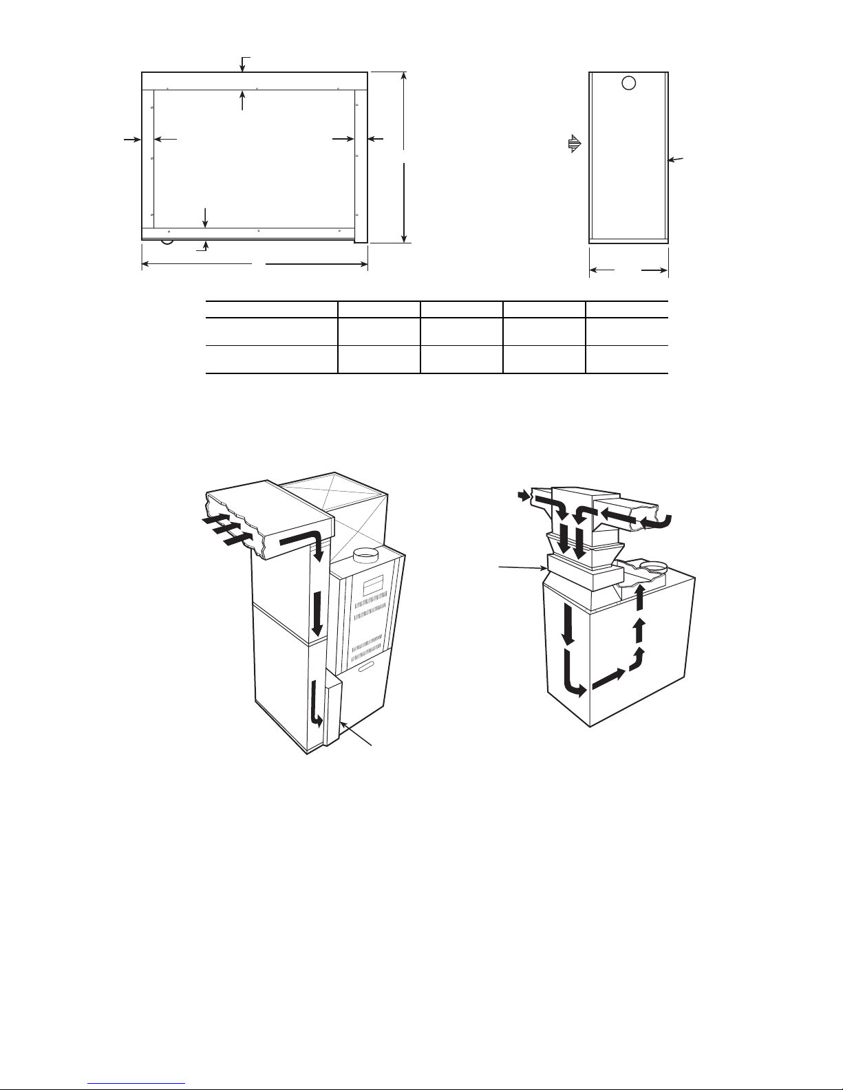
in the ductwork or air-handling equipment. See Fig. 2 for cabinet dimensions.
Filter —
will not shred or absorb moisture. The unique design of the filter includes a structured density gradient with a polarized
charge for higher initial and sustained efficiency. The filter media is supported by an open steel mesh and enclosed by a high
strength, beverage board. The filters have an Underwriters’
Laboratories Class 2 rating.
The efficiency of the filter is based on ASHRAE (American
Society of Heating, Refrigeration and Air Conditioning Engineers) Standard 52.2P. The maximum veloci ty is 500 ft/min.
An arrow indicates direction of airflow.
The cabinet is constructed of heavy gage galva-
The filter is constructed of polyolefin fibers that
Manufacturer reserves the right to
discontinue, or change at any time,
specifications or designs without notice
and without incurring obligations.
REPLACEMENT COMPONENTS DIVISION
© CARRIER CORPORATION 3/01 LITERATURE NUMBER AC-1SI
PRINTED IN U.S.A. CATALOG NUMBER 570-617
Page 2
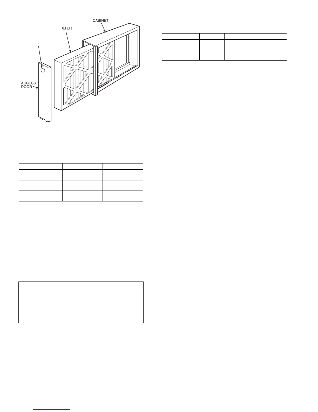
Table 2 — Media Air Cleaner Pressure Drop
(in. wg)
PLASTIC
KNOB
Fig. 1 — Media Air Cleaner
Table 1 — Specifications
PART NUMBER P102-BB14A P102-BB20
House Size Area
Airflow
Duct Size
< 3000 ft
< 278.70 m
up to 1400 CFM
up to 2379 m
16 x 25 in.
405 x 635 mm
2
2
3
/hr
> 3000 ft
> 278.70 m
up to 2000 CFM
up to 3398 m3/hr
20 x 25 in.
510 x 635 mm
2
2
INSTALLATION
Location —
return air duct, as close to the blower compartment as possible.
This location provides the most even airfl ow across the filter
and allows the media air cleaner to keep the system motor and
blower clean. See Fig. 3. When choosing location, there must
be adequate room to remove filters.
NOTE: Be sure to notify home owner not to install any device
within 3 ft from the side of the media air cleaner after installation is complete. Regular servicing of the medi a air cleaner is
required. A 3 ft clearance is required to remove filters for
maintenance or replacement.
IMPORTANT: The media air cleaner will cause
more of a restriction of your heating or cooling system than a regular furnace filter due to its increased
efficiency. As the filter collects contaminants, the
pressure drop increases. The media air cleaner is not
recommended in systems where pressure drop is
critical. See Table 2 for pressure drop information.
The media air cleaner must be installed in the
PART NUMBER CFM PRESSURE DROP (in. wg)
P102-BB14A
P102-BB20
700
1400
1000
2000
0.077
0.26
0.079
0.26
INSTALLATION LOCATION WITH HUMIDIFIER — If
a separate humidifier is purchased, it should be installed in the
furnace warm air duct. However, a humidifier may be installed
in the return air duct without causing problems to the media air
cleaner. Care must be taken to ensure that the humidifier does
not leak, as this may cause damage to the media air cleaner and
mineral deposits on the filter.
An atomizing-type humidifier should only be installed
downstream of the media air cleaner. If the atomizing-type humidifier is installed upstream, high humidity, salts, and minerals may damage the filter and cause service problems.
If the atomizing-type humidifier must be installed upstream,
the atomizing-type humidifier must be installed as far from the
media air cleaner as possible.
INSTALLATION LOCATION WITH AIR CONDITIO NER — Whenever possible, the media air cleaner should
be installed upstream of the cooling coil. This location will
clean the air before it reaches the evaporator coil.
Media Air Cleaner Installation —
Perform the fol-
lowing to install the media air cleaner.
1. Remove the existing furnace filter. Thoroughly clean
the blower compartment and ductwork where the
media air cleaner is to be installed.
2. Remove access door by uns crewing plas tic kno b. Slide
the filter out of the cabinet.
3. Place cabinet in ductwork. Holes are provided to
attach cabinet to ductwork or equipment. If the adjoining ductwork is flanged, install the screws so that the
screw heads are inside the cabinet. This will help prevent damage to filters during removal for cleaning.
When the air duct does not fit the media air cleaner
opening, a gradual transition is recommended to
reduce air turbulence through the media air cleaner and
to increase its efficiency. There should not be more
than 20 degrees of expansion used on each side of
the transition fitting. Do not reduce ductwork to a
smaller media air cleaner or it will increase the velocity of airflow.
4. If the media air cleaner is installed adjacent to an
elbow or angel fitting, turning vanes are recommended
to improve air distribution across the filter.
5. After media air cleaner has been secured, seal seams
airtight with duct tape or caulking to prevent dust from
entering the system.
6. Replace filter. Make sure arrow on filter is pointing
towards the fan. Replace the access door.
2
Page 3
D
C
C
RETURN AIR
C
A
B
AIR FLOW
LEFT TO RIGHT
OR
RIGHT TO LEFT
7 1/2"
UNIT ABCD
P102-BB14A
P102-BB20
1
17
(435)
22
(560)
/
16
26
(660)
26
(660)
1
(25)
1
1
(30)
/
4
1
2
(55)
23/
(60)
/
8
8
Fig. 2 — Dimensions
RETURN AIR
RETURN AIR
ACCESS DOOR
RETURN AIR
MEDIA AIR
CLEANER
NOTE: Provide a 3 ft (.914 m) clearance for filter removal.
Fig. 3 — Media Air Cleaner Installation Location
MEDIA
AIR
CLEANER
3
Page 4
OPERATION
For maximum performance of the media air cleaner, these
steps should be followed:
• run your heating/cooling system fan continuously
• remove furniture or carpets which block return air grilles
throughout your house, so that air moves freely to the
furnace
• check for proper operation of the blower fan on the
furnace
• ensure that the filter is not clogged.
After installation of the media air cleaner, you may notice
some white dust on table tops and shelves. Most heavy
particles (such as lint) settle quickly and do not get filtered
through the media air cleaner. To reduce lint and dust, use
continuous fan operation and keep return vents unrestricted to
create an efficient airflow.
MAINTENANCE
It is very important that the scheduled maintenance be done
by the home owner. If the filter is not changed on a regular
basis, the media air cleaner will not operate effectively.
Make sure to turn furnace off before performing any maintenance or removing air components.
Filter Replacement —
The filter will need to be replaced once or twice a year, depending on the amount of contaminants in the air. See Table 2. If the filter becomes clogged,
airflow through the system may be restricted. This may cause
service problems with the furnace or air conditioner.
T o replace the filter:
1. Turn off furnace fan.
2. Open media air cleaner access door by unscrewing
plastic knob.
3. Remove filter from cabinet and discard.
4. Install new filter. Make sure arrow points toward the
furnace fan.
5. Replace access door.
6. Turn on furnace fan.
Table 2 — Replacement Filters
PART NUMBER
P102-BB14A
P102-BB20
REPLACEMENT
FILTER PART NO.
P102-1625BB
P102-2025BB
FILTER SIZE (in.)
3
15
/8 x 251/2 x 51/
1
20
/4 x 253/8 x 51/
4
4
4
Page 5
MEDIA AIR CLEANER
LIMITED ONE-YEAR WARRANTY
LIMITED ONE-YEAR WARRANTY —
This CARRIER CORPORATION product is warranted to be free from
defects in material and workmanship under normal use and maintenance for one year. The warranty does not
apply to replacement of the disposable media filter, which will need to be replaced once or twice a year depending on usage. A new or remanufactured part to replace the defective part will be provided without charge for the
part itself, through a qualified servicing CARRIER CORPORATION dealer or service PROVIDED the defective
part is returned to our distributor.
THIS WARRANTY DOES NOT INCLUDE ANY ADDITIONAL LABOR ALLOWANCE,
or other costs incurred
for diagnosis, repairing, removing, installing, shipping, servicing, or handling of either defective parts or replacement parts. SUCH COSTS MAY BE COVERED BY a separate warranty provided by the installer.
LIMITATIONS OF WARRANTIES —
ALL IMPLIED WARRANTIES (INCLUDING IMPLIED WARRANTIES OF
MERCHANTABILITY) ARE HEREBY LIMITED IN DURATION TO THE PERIOD FOR WHICH THE LIMITED
WARRANTY IS GIVEN. THE EXPRESSED WARRANTIES MADE IN THIS WARRANTY ARE EXCLUSIVE
AND MAY NOT BE ALTERED, ENLARGED, OR CHANGED BY ANY DISTRIBUTOR, DEALER, OR OTHER
PERSON WHATSOEVER.
ALL WORK UNDER THE TERMS OF THIS WARRANTY SHALL BE PERFORMED DURING NORMAL WORKING HOURS. ALL REPLACEMENT PARTS, WHETHER NEW OR REMANUFACTURED, ASSUME AS THEIR
WARRANTY PERIOD ONLY THE REMAINING TIME PERIOD OF THIS WARRANTY.
CARRIER WILL NOT BE REPONSIBLE FOR:
1. Normal maintenance as outlined in the installation instructions including replacement of media filters.
2. Damage or repairs required as a consequence of faulty installation or application by others.
3. Damage or repair needed as a consequence of any misapplication, abuse, improper servicing, unauthorized
alteration or improper operations
4. Damage as a result of floods, winds, fires, lightning, accidents, corrosive atmosphere, or other conditions
beyond the control of CARRIER CORPORATION.
5. Parts not supplied or designated by CARRIER CORPORATION.
6. CARRIER CORPORATION products installed outside the continental U.S.A., Alaska, Hawaii and Canada.
7. ANY SPECIAL INDIRECT OR CONSEQUENTIAL PROPERTY OR COMMERCIAL DAMAGE OF ANY
NATURE WHATSOEVER. Some states do not allow the exclusion of incidental or consequential damages, so
the above limitation may not apply to you.
Model No. Unit Serial No.
Date of Installation Installed by
Name of Owner Address of Installation
Replacement Components Division • Carrier Corporation
Syracuse, New York
5
Page 6

Page 7

Page 8
Your Assurance of Quality
ALL Totaline® products are backed with a one-year
warranty by Carrier Corporation, the world’s largest
manufacturer of air conditioning, heating, and
refrigeration products.
Manufacturer reserves the right to
discontinue, or change at any time,
specifications or designs without notice
and without incurring obligations.
REPLACEMENT COMPONENTS DIVISION
©
CARRIER CORPORATION 3/01 LITERATURE NUMBER AC-1SI
PRINTED IN U.S.A. CATALOG NO. 570-617
 Loading...