

TOTALINE P102-400DM Installation & Operation Manual
INSTALLATION, OPERATION,
AND MAINTENANCE
INSTRUCTIONS
Part Number: P102-400DM
Whole House
Duct-Mount
HEPA Air Cleaner
TABLE OF CONTENTS
Page
SAFETY CONSIDERATIONS......................1
INTRODUCTION .................................1,2
INSTALLATION ..................................2,3
Location .........................................2
Duct Mount Installation ..........................3
Collar Mount Installation .........................3
OPERATION......................................3
MAINTENANCE .................................3,4
WHOLE-HOUSE HEPA AIR CLEANER
LIMITED FIVE YEAR WARRANTY................. 5
SAFETY CONSIDERATIONS
Read and follow instructions carefully. Follow all local
electrical codes during installation. All wiring must conform to
local and national electrical codes. Improper wiring or installation may damage the HEPA (High-Efficiency Particulate Air)
air cleaner.
Understand the signal words WARNING and CAUTION
which are present in the Owner’s Manual. WARNING signifies a hazard or unsafe practices that could result in severe personal injury or death. CAUTION signifies a potential hazard or
unsafe practice which could result in minor personal injury or
property damage.
INTRODUCTION
The Whole-House HEPA Air Cleaner has been designed to
remove particulate such as atmospheric and household dust,
coal dust, insecticide dust, mites, pollen, mold spores, fungi,
bacteria, viruses, pet dander, cooking smoke and grease,
tobacco smoke and more. The air cleaner has a carbon filter
that removes odors. See Fig. 1.
• Helps provide relief from allergies, asthma, and other
respiratory illness.
• Helps reduce housekeeping time and redecorating costs.
• Provides a healthier, more comfortable environment,
year-round.
Millions of airborne pollutants are carried through the return
air ducts of the heating/cooling system. The HEPA air cleaner
has been designed to be installed on the return air duct. A portion of this return air is bypassed through an opening on the
rear of the unit and passes through a 3-stage filtration system.
The air passes through an efficient pleated MERV 8
(Minimum Efficiency Reporting Value) prefilter to remove lint
and large particles to extend the life of the HEPA filter.
The activated carbon filter (activated carbon impregnated
polyester filter) removes odors before they enter the HEPA
filter.
Before beginning any installation or modification, be certain that the main line electrical disconnect switch is in the
OFF position. Electric shock could result. Tag disconnect
switch with suitable warning labels.
Only a heating and air conditioning installer or qualified
service person should install, repair, or service the WholeHouse HEPA Air Cleaner.
Homeowners or untrained personnel can perform the basic
maintenance functions of replacing filters.
When working on air cleaning equipment, observe precautions in the Owner’s Manual, labels attached to the unit,
and other safety precautions that may apply. Follow all
safety codes. Wear safety glasses and work gloves.
Manufacturer reserves the right to
discontinue, or change at any time,
specifications or designs without notice
and without incurring obligations.
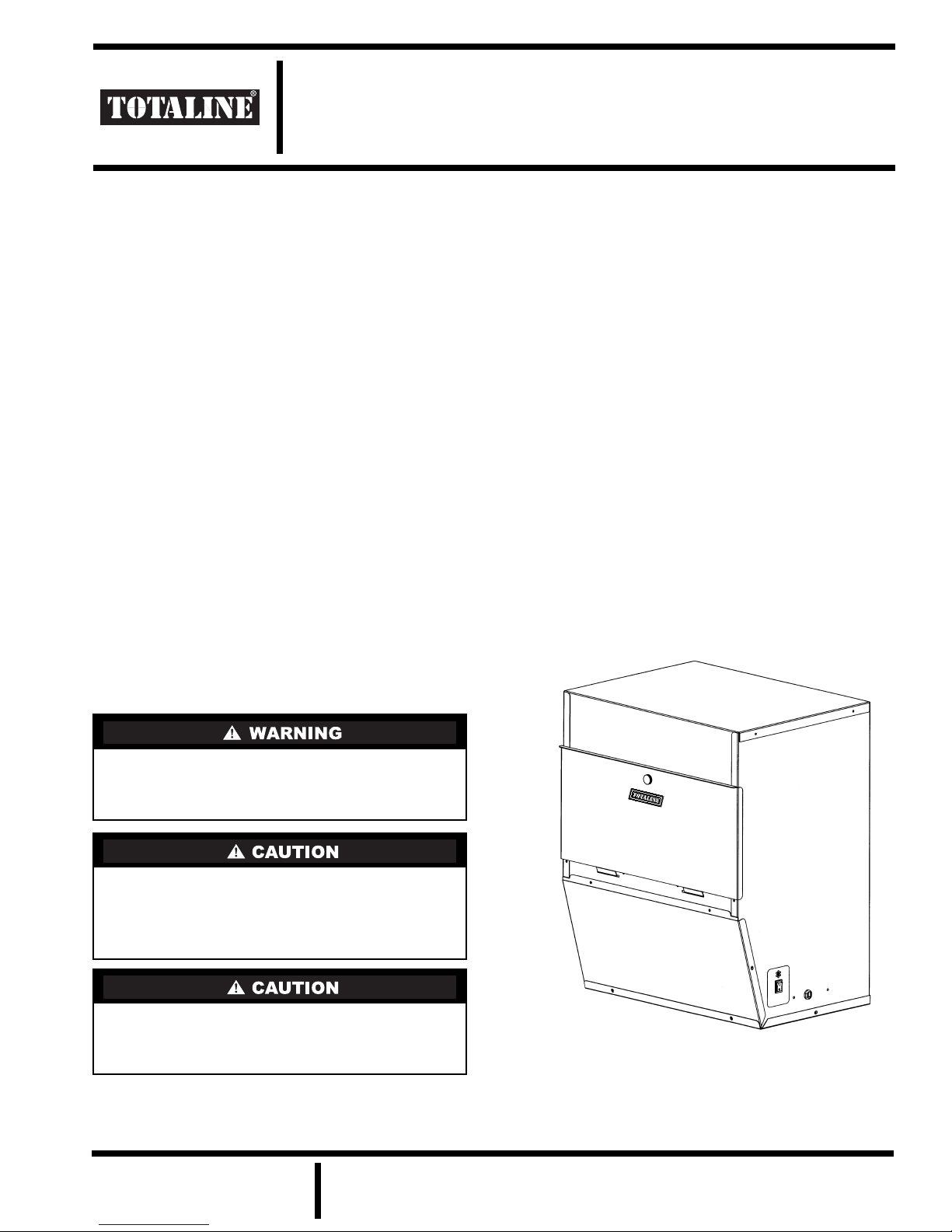
Fig. 1 — P102-400DM Unit
REPLACEMENT COMPONENTS DIVISION
© CARRIER CORPORATION 2005 2-05 LITERATURE NUMBER P102-8SI
PRINTED IN U.S.A. CATALOG NUMBER 570-356
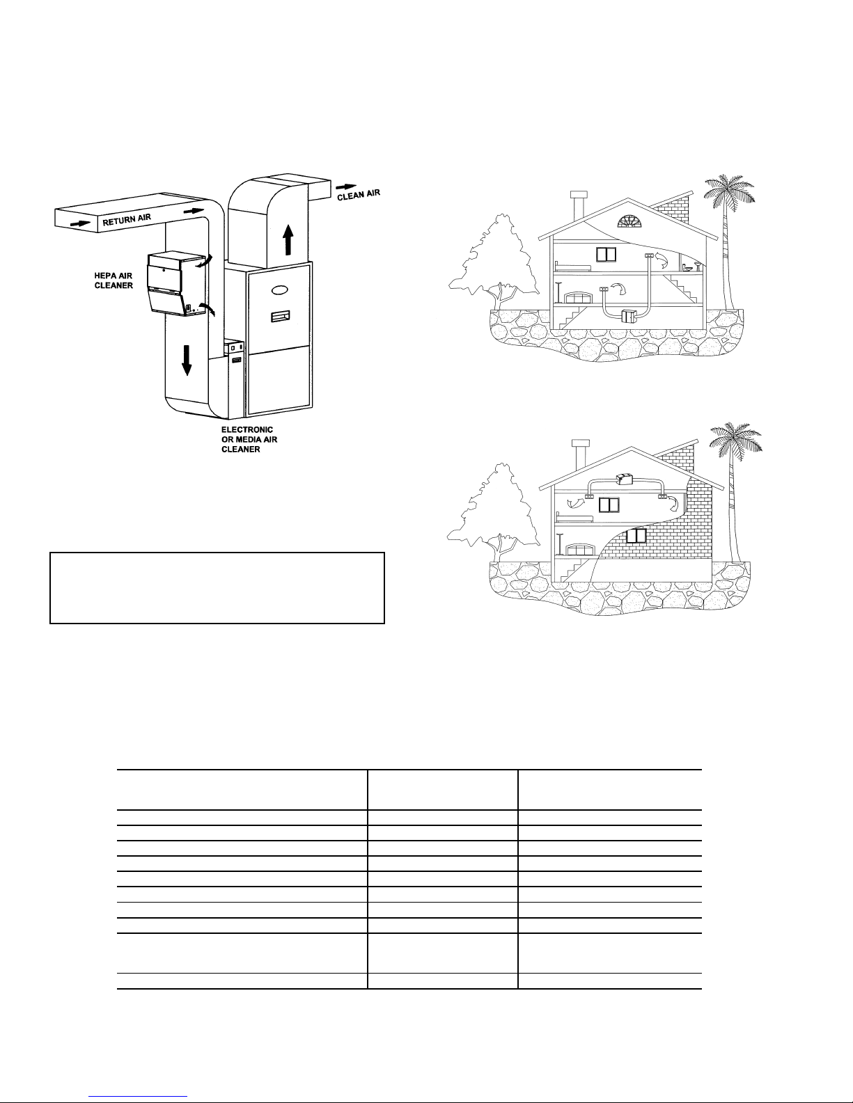
Smaller particles then pass through a long-life, HEPA (High
Efficiency Particulate Air) filter which captures 99.97% of
particles 0.3 micron (1/84,000 of an inch) and larger. This
HEPA filter has more than 40 sq ft of collection surface area.
See Table 1.
Clean air is discharged back into the return air duct. See
Fig. 2.
unit into the return air plenum when suspended from the ceiling. It can also be used as a free-standing unit (see Fig. 3 and
4). Care should be taken to keep the unit away from an area
where there is a possibility of moisture leaking onto the unit.
Ensure there is adequate room in front of the unit to remove the filters for replacement.
Fig. 3 — Self-Contained Basement Installation
Fig. 2 — Duct Mount Installation
INSTALLATION
Location
IMPORTANT: This unit must be installed on the return
air side of the system only. Do not connect to supply
side. Do not install in a cooking area or connect directly
to any appliance.
The HEPA air cleaner can be installed directly on the return
air duct, eliminating the need for external ducting. The unit can
also be mounted on the floor or a wall. Use collars to duct the
Table 1 — Physical Data
Dimensions Height 20.125 in. 51.1 cm
Width 16.25 in. 41.3 cm
Depth 12.75 in. 32.4 cm
Intake 14.5 x 3.75 in. or 8 in. (dia) 36.8 x 9.5 cm or 20.3 cm (dia)
Outflow 14.5 x 4.37 in. or 8 in. (dia) 36.8 x 11.1 cm or 20.3 cm (dia)
Unit Weight 38 lb 17.2 kg
Input Voltage 120 V 60 Hz
Power Consumption 125 Watts
Airflow 320 cfm
Cabinet 22 gage
Power Cord 9.0 ft 2.74 m
Filter Dimensions Prefilter 16 x 12 x 1 in. 40.6 x 30.5 x 2.5 cm
HEPA Filter 16 x 12 x 2.5 in. 40.6 x 30.5 x 5 cm
Carbon Filter 16 x 12 x .5 in. 40.6 x 30.5 x 1.3 cm
HEPA Collecting Surface Area 40 sq ft 3.7 sq m
Fig. 4 — Self-Contained Attic Installation
3
544 m
/hr
2
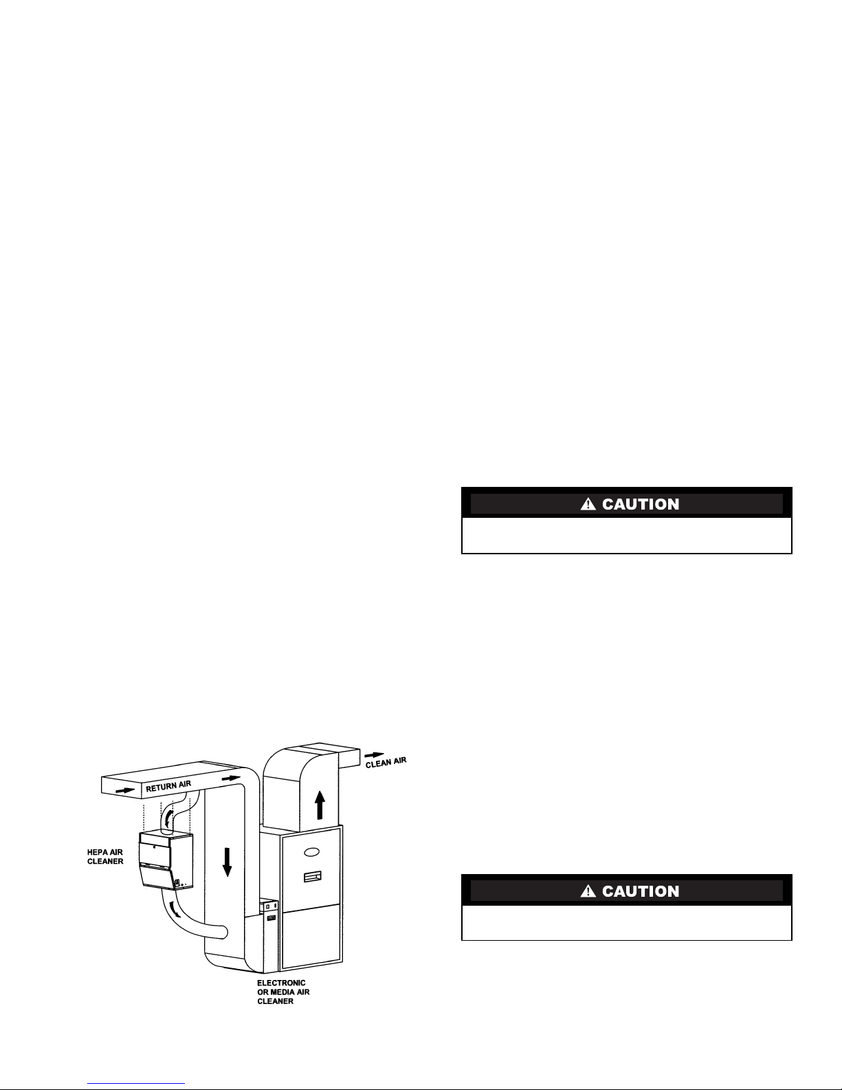
Duct Mount Installation
1. Remove any packaging, as well as the door and filters
before installing. See Maintenance for instructions to
remove the filters.
2. If the unit is to be mounted on the return air plenum, it
must be installed after the last return branch connection on the plenum. If outside air is introduced into the
return air duct, either through a HRV (Heat Recovery
Ventilator) or directly, it should be added to the system
before the intake inlet to the air cleaner.
3. Tape the mounting template level on the plenum and
cut and drill the necessary holes as marked.
4. Cut the small joints on the mounting flaps on the back
of the unit as indicated. Bend all the flaps outward
slightly less than 90 degrees, except for the upper bottom flap which should be bent up at a 40 degree angle
only. This bottom flap will act as a deflector for the
exhaust air entering back into the plenum.
5. Place the gasket material around the two openings on
the back of the air cleaner. Place the unit on the plenum so the flanges are placed through the holes cut in
the duct. Fold all the flanges over, except for the upper
bottom flap, to enclose the duct between the flanges
and the unit. The upper bottom flap should be bent up
at a 40 degree angle only.
6. Secure the unit to the duct with the screws provided.
Collar Mount Installation — Inlet collars are available
as a kit from the distributor. See Fig. 5.
1. This unit can be installed with collars and flexible
ducting if desired. Openings are prepunched on the top
and bottom of the unit for this purpose. Remove the
plastic film over the holes and snip out the joints to
open the hole. Do not open the holes in the back of the
unit if the air cleaner is being collar mounted.
2. The collar is installed with the flange on the inside of
the cabinet with only the collar ring on the outside of
the cabinet. Compress the collar until a flange can be
inserted into the opening in the enclosure. Enlarge the
collar to its maximum and install two screws into the
ring to hold it to the proper diameter. Turn the collar in
the hole until the holes in the enclosure line up to the
holes on the collar flange. Secure with the screws
provided.
3. The intake collar on the return duct must be installed
after the last return branch connection on the plenum.
If outside air is introduced into the return air duct,
either through a HRV (Heat Recovery Ventilator) or
directly, it should be added to the system before the
intake inlet to the air cleaner.
4. The 8 in. intake collar (top) must draw air from the
return duct at a location that will be ahead of the clean
exhaust air, that will be returned to the duct from the
air cleaner.
5. An 8 in. collar will be installed on the return duct and
a length of 8 in. flexible hose or duct is required to
attach between the 8 in. intake collar and the collar on
the return duct. When running the hose, make sure that
there are no kinks or sharp bends that will impede the
airflow to the unit. Secure and seal the hose or duct
and connections to prevent air leakage.
6. The 8 in. exhaust collar can be mounted in the same
manner to the bottom of the unit. An 8 in. collar will
be installed on the return duct close to the furnace and
a length of 8 in. flexible hose or duct is required to
attach between the exhaust collar and the collar on the
return duct. The ideal location is low on the return air
boot pointing at the furnace. To prevent air shear
inside the duct, it is recommended that a deflector be
installed inside the boot, so the discharged air is
deflected down into the boot. When running the hose,
make sure that there are no kinks or sharp bends that
will impede the airflow from the unit. Secure and seal
the hose and connections to prevent air leakage.
OPERATION
Do not use the unit without all of the filters in place. The
HEPA filter life will be reduced.
The HEPA air cleaner is designed to run continuously to
provide clean, filtered air 24 hours a day. The fan on the
heating/cooling system, to which the HEPA air cleaner is dependent on for circulated air, should be on ‘continuous’.
NOTE: If the system fan setting is on ‘automatic’, it is recommended that the HEPA air cleaner be operated through an air
switch or relay to turn the air cleaner off when there is no system fan on.
The unit plugs into a regular 120 volt outlet and is
controlled by a switch located on the bottom of the unit, near
the cord.
NOTE: Do not place the cord where it might be walked on or
where something might be rolled over the cord.
The door must be secured for the air cleaner to operate. All
filters must be in place for the unit to operate properly.
Fig. 5 — Collar Mount Installation
MAINTENANCE
For efficient operation, the filters must be changed on a
regular basis. If you notice a reduction in airflow from the system, check the filters. See Fig. 6.
Make sure to turn air cleaner OFF before performing any
maintenance or removing any components.
1. To access the filters, turn the air cleaner OFF at the
switch and remove the front door.
2. Carefully remove filters to avoid spilling collected
contaminants. Dispose of filters in a plastic bag and
discard with regular household trash.
3
 Loading...