

TOTALINE IntelliMist Owner's Manual
OWNER'S MANUAL
INTELLIMIST
HUMIDIFIER
TOTALINE
TM
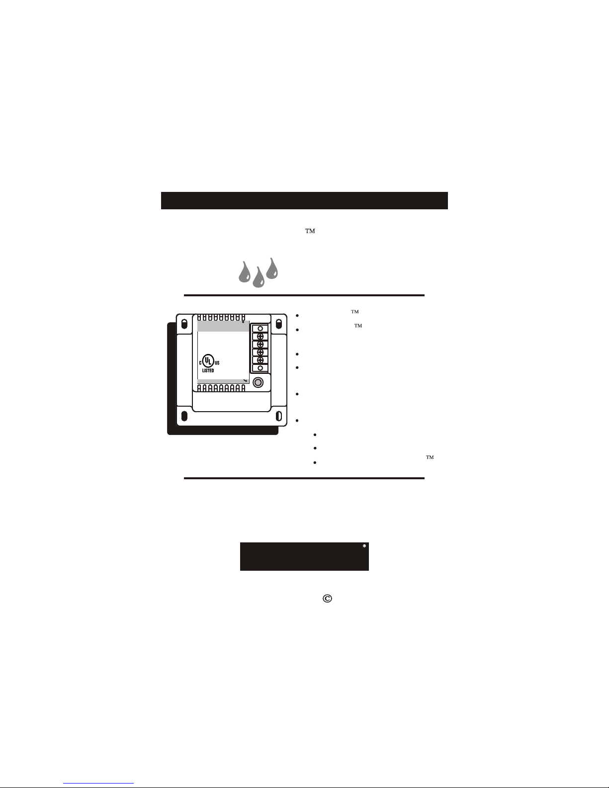
TM
IntelliMist
Humidifier
MODEL P11 0-300
4Z95
24vac 7.5w
For
Residential
Use Only
Intellimist
R
C
H1
H2
On
P/N P110-300
INTELLIMIST MicroFine Spray
MICROPULSE Technology
Assures Maximum Efficiency
Scale Reducing Filter Included
Up to 24 Gallons Per Day of
Additional Humidity
For Use With 1 - 7 Ton HVAC
Systems
Designed For Use Only With:
P110-0009 Humidistat
P474-3000 Humidistat
P374-1600 INTELLISTAT
USE ONLY WITH CENTRAL AIR CONDITIONING SYSTEMS.
THE HUMIDIFIER MUST BE MOUNTED OVER THE
EVAPORATOR COIL OR EVAPORATOR COIL DRAIN PAN.
IF THERE IS NOT A DRAIN PAN, ONE MUST BE INSTALLED.
Replacement Components Division Carrier Corporation 3/01
TOTALINE
PATENTS PENDING

INTELLIMIST HUMIDIFIER
TABLE OF CONTENTS
CONTENTS & ACCESSORIES.....................2
MOUNTING LOCATIONS..............................3
ASSEMBLY & INSTALLATION.......................4
WATER HARDNESS......................................6
WATER FILTER..............................................7
WIRING DIAGRAMS......................................8
TROUBLE SHOOTING GUIDE.....................11
OUTPUT CHECK..........................................16
Page 1
INTELLIMIST HUMIDIFIER
CAUTION
This Humidifier MUST be used with Totaline
P110-0009, P474-3000 Humidistats or P374-1600 INTELLISTAT.
Follow Installation Instructions for Humidifier carefully.
UNIT MUST NOT BE INSTALLED WHERE FREEZING TEMPERATURES
MAY OCCUR. DO NOT INSTALL ON FURNACE JACKET, OR WHERE
UNIT AND ITS COMPONENTS MAY COME INTO CONTACT WITH HOT SURFACES.
PACKAGE CONTENTS
P110-300 INTELLIMIST Humidifier Assy.
#0862 Tube Assy.
#0759 INTELLIMIST In-Line Water Filter
#0800 Water Filter Mounting Bracket
#0152 Mounting Kit
AVAILABLE INTELLIMIST ACCESSORIES
P110-0009 Humidistat
P474-3000 Humidistat
P374-1600 INTELLISTAT
(Combination Thermostat / Humidistat)
P110-0008 Replacement Filter / Nozzle
USE ONLY WITH CENTRAL AIR CONDITIONING SYSTEMS.
THE HUMIDIFIER MUST BE MOUNTED OVER THE
EVAPORATOR COIL OR EVAPORATOR COIL DRAIN PAN.
IF THERE IS NOT A DRAIN PAN, ONE MUST BE INSTALLED.
Page 2
INTELLIMIST HUMIDIFIER
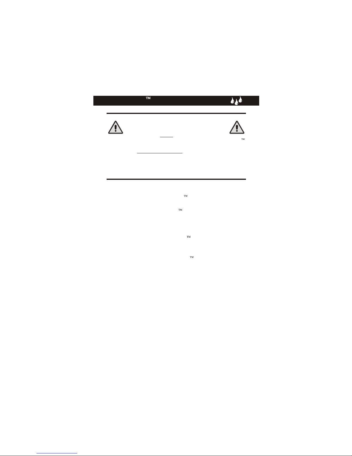
SELECT MOUNTING LOCATION
11
1. The humidifier should be installed on the supply plenum,
preferably near the coil. Mounting near the evaporative
coil, if applicable, will allow any excess moisture to exit
the system via the condensation drain pan.
2. On vertical equipment allow clearance of the humidifier
and related components such as the water filter and
plastic water live, from the exhaust vent.
3. On vertical equipment, if the nozzle is spraying away
from the coil, there should be a minimum of three feet
from the nozzle to the top of the plenum. If this is not
available, then point the nozzle of the humidifier
directly into the evaporative coil.
4. Always install downstream of an electronic air cleaner.
Drill or ‘knock out’ a 1” hole & 4 mounting holes for the
#6 screws on the mounting template.
PLENUM
AIR FLOW
HORIZONTAL
EQUIPMENT
PLENUM
VERTICAL
EVAPORATOR
N-COIL
FURNACE
DRAIN
PAN
EVAPORATOR
COIL
PLENUM
HUMIDIFIER
ALTERNATE
LOCATION
VERTICAL
EVAPORATOR
DRAIN PANS
FURNACE
Page 3
HUMIDIFIER
A-COIL
FURNACE
HUMIDIFIER
ALTERNATE
LOCATION
INTELLIMIST HUMIDIFIER
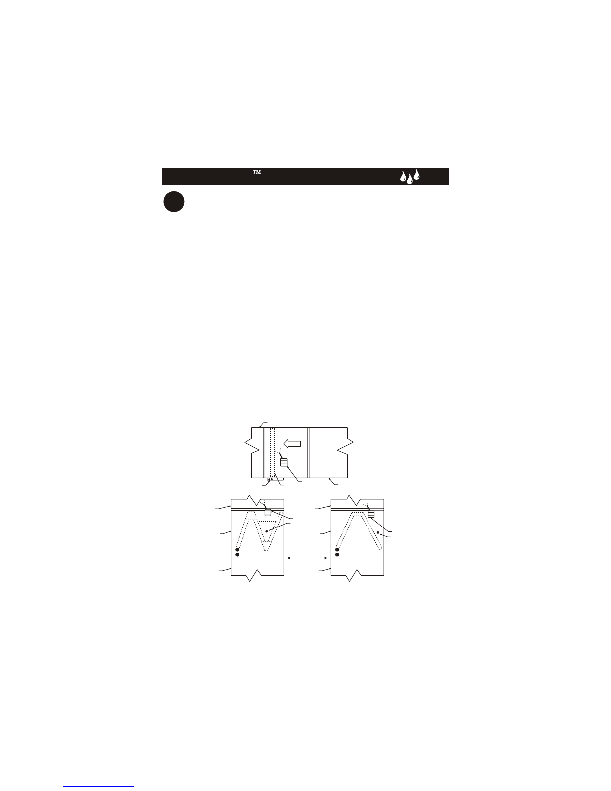
22
ASSEMBLE THE HUMIDIFIER
Slide the mounting nut over the tube
(fig. 1)
MOUNTING NUT
assembly.
Insert the tube assembly into the humidifier
valve. Secure by turning the nut clockwise
until finger tight, then additional 1/4 turn.
(fig. 2)
33
INSTALL THE HUMIDIFIER
Be sure to use a cold water
connection.
Mount the humidifier to the sheet
metal using the four #6 mounting
screws supplied. (Page 3)
The in-line water filter should be
mounted below or to one side of
the humidifier assembly in a vertical
position as shown. (Fig. 3)
Fig. 1
Fig. 2
TOTALINE
INTELLIMIST
HUMIDIFIER
MODEL: P110-300
24 VAC 7.5 WATTS
UU
LL
US
C
LISTED
4Z95
TUBE ASSY
RR
CC
H1H1
H2H2
INTELLIMIST
ON
Fig. 3
Be sure the flow arrow on the filter is
pointing to the humidifier.
Page 4
INTELLIMIST HUMIDIFIER
44
WATER CONNECTION
Run 1/4” tubing from the water supply to the
in-line filter. The saddle valve and tubing
is supplied for this purpose.
SADDLE VALVE INSTALL
The self piercing
is for copper pipe
of pipe, drill a 1/8” hole in the pipe. Turn the
handle clockwise to expose the piercing pin
beyond the seal approximately 3/16”. Place
the body of the valve over the hole in the
pipe so the pin fits in the hole. Tighten the
bottom clamp evenly. Turn handle clockwise
and close the valve.
feature of the saddle valve
only. All other materials
USE COPPER TUBING WHERE INSTALLATIONS
MAY CAUSE DAMAGE IF A WATER LEAK OCCURS.
CAUTION
SAFETY NOTE
Page 5
 Loading...