

TOTALINE Gold P274-1100, Gold P274-1200, Gold P274-1300 Installation And Operating Instructions Manual
TOTALINE
1c.eps
gold-1.pdf
INSTALLATION
AND OPERATING
INSTRUCTIONS
Par t No. P274-1100, 1200, 1300
Residential
Programmable
Thermostats
CONTENTS
Page
SAFETY CONSIDERATIONS. . . . . . . . . . . . . . . . . . . . . . 1
GENERAL . . . . . . . . . . . . . . . . . . . . . . . . . . . . . . . . . . . . . . . . 1
INSTALLATION CONSIDERATIONS . . . . . . . . . . . . . .1,2
Models . . . . . . . . . . . . . . . . . . . . . . . . . . . . . . . . . . . . . . . . . . . 1
Outdoor Temperature Sensing . . . . . . . . . . . . . . . . . . . 1
INSTALLATION . . . . . . . . . . . . . . . . . . . . . . . . . . . . . . . . 2-14
Step 1 — Thermostat Location . . . . . . . . . . . . . . . . . . . 2
Step 2 — Set DIP Switches . . . . . . . . . . . . . . . . . . . . . . . 2
Step 3 — Install Thermostat . . . . . . . . . . . . . . . . . . . . . . 2
Step 4 — Space Temperature Averaging . . . . . . . . 10
Step 5 — Set Thermostat Configuration . . . . . . . . . 10
Step 6 — Check Thermostat Operation. . . . . . . . . . 12
Step 7 — Select Thermostat Operation
Settings. . . . . . . . . . . . . . . . . . . . . . . . . . . . . . . . . . . . . . . 13
Step 8 — Set Current Time . . . . . . . . . . . . . . . . . . . . . . 13
Step 9 — Set Current Day . . . . . . . . . . . . . . . . . . . . . . . 13
Step 10 — Programming Thermostat
Schedules . . . . . . . . . . . . . . . . . . . . . . . . . . . . . . . . . . . . 13
Step 11 — Final Checklist . . . . . . . . . . . . . . . . . . . . . . . 13
OPERATION. . . . . . . . . . . . . . . . . . . . . . . . . . . . . . . . . . .14,15
Hold, Fan, and Mode Button Operation. . . . . . . . . . 14
Outdoor Temperature . . . . . . . . . . . . . . . . . . . . . . . . . . . 14
Thermostat Output Assignments. . . . . . . . . . . . . . . . 14
Five-Minute Compressor Timeguard . . . . . . . . . . . . 14
Fifteen-Minute Cycle Timer. . . . . . . . . . . . . . . . . . . . . . 14
Fifteen-Minute Staging Timer. . . . . . . . . . . . . . . . . . . . 14
Three-Minute Minimum On Time . . . . . . . . . . . . . . . . 14
Heating/Cooling Set Points. . . . . . . . . . . . . . . . . . . . . . 14
Auto-Changeover Timer. . . . . . . . . . . . . . . . . . . . . . . . . 14
Power-On Check . . . . . . . . . . . . . . . . . . . . . . . . . . . . . . . . 14
Error Codes . . . . . . . . . . . . . . . . . . . . . . . . . . . . . . . . . . . . . 15
Smart Recovery (Heating Mode Only) . . . . . . . . . . . 15
TROUBLESHOOTING. . . . . . . . . . . . . . . . . . . . . . . . . . . . 15
PROGRAMMABLE THERMOSTAT
CONFIGURATION RECORD . . . . . . . . . . . . . . . . . . . 16
IMPORTANT: Read entire instructions before starting the installation.
SAFETY CONSIDERATIONS
Read and follow manufacturer instructions carefully. Fol-
low all local electrical codes during installation. All wiring
must conform to l ocal and national electrical codes. Improper
wiring or installation may damage the thermostat.
Recognize safety information. This is the safety al ert symbol . When the safety alert symbol is present on equipment
or in the instruction manual, be alert to the potential for personal injury.
Understand the signal words DANGER, WARNING, and
CAUTION. These words are used with the safety alert symbol.
DANGER identifies the most serious hazards which will result
in severe personal injury or death. WA RNING signifies a ha z
ard which could result in personal injury or death. CAUTION
is used to identify unsafe practices which would result in minor
personal injury or property damage.
-
GENERAL
T otaline® 7-day, programmable thermostats are wall-mounted, low-voltage thermostats which maintain room temperature
by controlling the operation of an HVA C ( heating, vent ilation,
and air-conditioning) system. Separate heating and cooling set
points and auto-changeover capability allow occupied and un
occupied programming for energy savings.
All programmable thermostats allow up to 4 t ime/temperature settings to be programmed per 24-hr period. Each thermostat stores programs for 7 independent days. Batteries are not
required. During power interruption, the internal memory
stores comfort schedules for an unlimited time while the clock
continues to run for at least 72 hours.
-
INSTALLATION CONSIDERATIONS
Models — There are 3 different models. Ensure the proper
thermostat is selected for the intended application. Refer to
Fig. 1 for thermostat dimensions. Select from the following
models:
1. P274-1100 (air conditioner [AC]) — 1-stage cool,
1-stage heat for air-conditioning systems only
2. P274-1200 (heat pump [HP]) — 1-stage cool, 2-stage
heat for either heat pump or air conditioner systems
with 2-stage heat
3. P274-1300 (2-speed) — 2-stage cool, 2-stage heat for
2-speed AC systems, or 2-stage cool, 3-stage heat for
2-speed HP systems, or 1-stage cool, 4-stage heat for
1-speed HP with special 3-stage electric heat
Outdoor Temperature Sensing — All programma-
ble thermostats can be equipped with an optional outdoor temperature sensor, part no. TSTATXXSEN01-B. If this option is
to be installed, plan thermostat installation so that 2 wires can
be run from the thermostat to an outdoor location. Refer to the
installation instructions provided with the outdoor temperature
sensor for necessary connections.
Manufacturer reserves the right to
discontinue, or change at any time,
specifications or designs without notice
and without incurring obligations.
REPLACEMENT COMPONENTS DIVISION LITERATURE NUMBER P274-8SI
© CARRIER CORPORATION 2007 1-07 REPLACES: NEW
PRINTED IN U.S.A. CATALOG NUMBER 570-502
HEIGHT (in.) WIDTH (in.) DEPTH (in.)
1
/
4
4
71/
2
13/
8
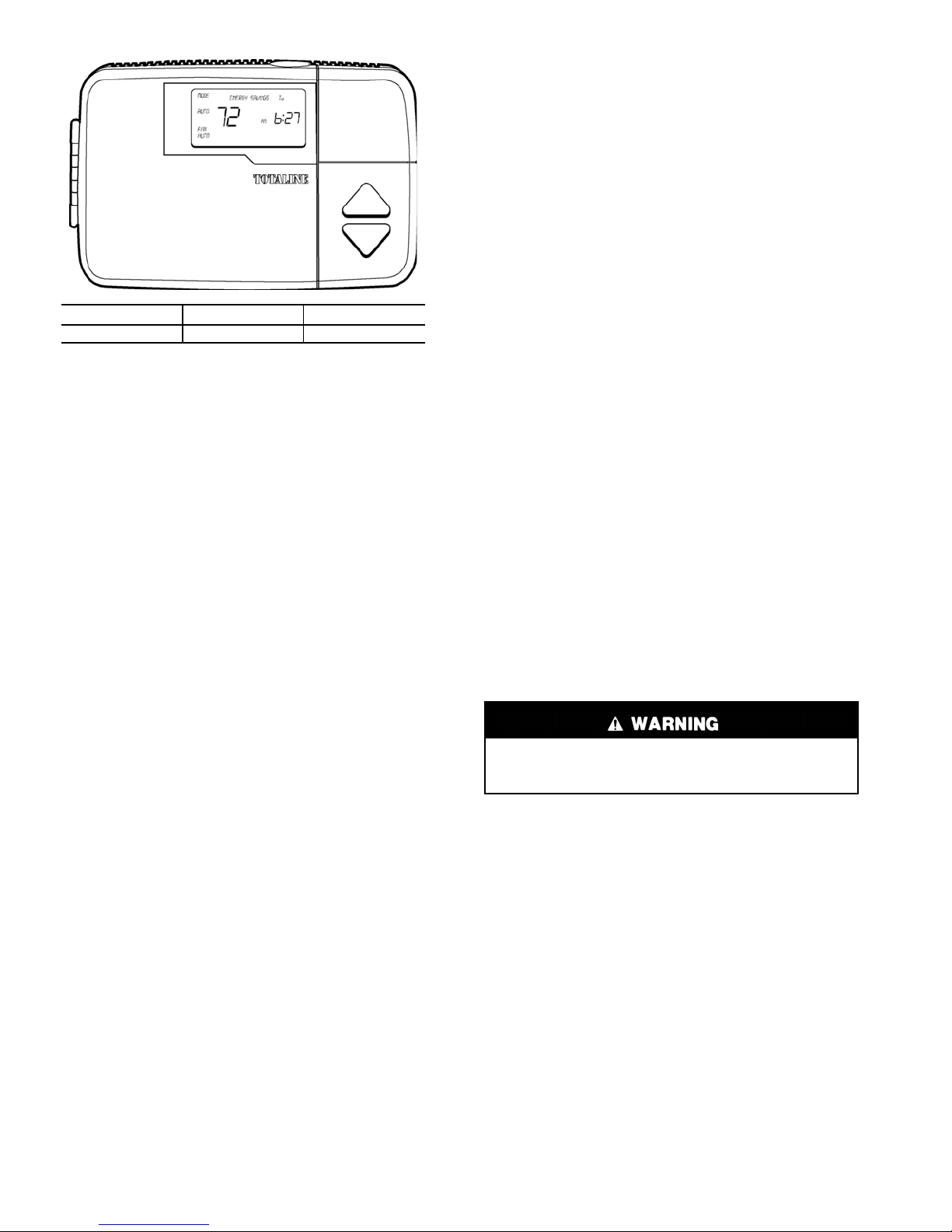
Fig. 1 — Totaline® Residential
Programmable Thermostat
INSTALLATION
Step 1 — Thermostat Location — The thermostat
should be mounted:
• approximately 5 ft from the floor
• close to or in a frequently used room, preferably on an
inside partitioning wall
• on a section of wall without pipes or ductwork
The thermostat should not be mounted:
• close to a window, on an outside wall, or next to a door
leading to the outside
• where exposed to direct light and heat from a lamp, the
sun, a fireplace, or any other temperature-ra diating object
which may cause a false reading
• close to or in direct airflow from supply registers or
return air grilles
• in areas with poor air circulation (such as behind a door
or in an alcove)
Step 2 — Set DIP Switches — To access the dual in-
line package (DIP) switches, remove the thermostat door from
the front and unhinge the back half of the the rmostat from the
front half.
There are 4 small DIP switches in the upper right of the circuit board which must be configured by the installer. The ON
position is indicated by small letters on the switch. Ignore the
numbers (1-4) on the switches. The switch designation (A-D)
is printed on the circuit board above the switches. To change a
switch position, use the corner of a small screw driver to slide
the switch ON or OFF.
Set the DIP switches before installing the thermostat and
record the settings on page 16. Once switches are set, do NOT
reassemble the halves of the thermostat . The bac k half will be
mounted to the wall.
ZONING SELECT — SWITCH A (Active on All Models ) —
Switch A controls the 4 cycles per hour limit and 5-minute
compressor timeguard that MUST be enabled for normal oper
ation. For zoning applications, turn the switch to ON and cancel the timers as the zone contr ol c enter pe rforms t hes e timing
functions.
TO SET:
OFF — Normal operation, factory default
ON — Zoned installations only
-
SETBACK RECOVERY — SWITCH B (Active on All
Models) — Use Switch B to select eithe r normal or smart re
covery from setback. Normal recovery changes to the new set
point at the programmed time. Smart recovery, which is active
in heating mode only, starts earlier and adjusts the set point
slowly so that room temperature will arrive at the programmed
temperature at the programmed time.
TO SET:
OFF — Smart recovery, factory default
ON — Normal recovery
HP/AC SELECT — SWITCH C (Active on 1200 and 1300
Models Only) — Use Switch C to select between AC and HP
installations. The 1200 and 1300 models have an extra relay to
control the HP reversing valve. When a 1200 model thermostat
is placed in AC mode, this extra relay is converted to a second
stage heat output. This allows thermostat control of 2-stage fur
naces or 2-stage strip heat with AC systems (AC mode wiring
also uses W rather than Y for first-stage heat).
TO SET:
OFF — HP applications (extra re la y controls reversing valve),
factory default
ON — AC applications (extra output can be used for 2-stage
heat)
INTELLIGENT HEAT STAGING SELECT — SWITCH D
(Active on 1300 Models Only) — Use Switch D to convert a
2-speed heat pump thermostat with 1 stage of auxiliary heat
into a 1-speed heat pump thermostat with 3 stages of auxiliary
heat for additional heating capacity. It requires selected heaters
with 2:1 ratio element sizes plus a variable-speed fa n coil. Re
fer to fan coil literature for details.
TO SET:
OFF — Normal 2-speed operation, factory default
ON — Intelligent 3-stage heat with a variable-speed fan coil
Step 3 — Install Thermostat
Before installing thermostat, turn off all power to the
unit. There may be more than one power disconnect.
Electrical shock can cause injury or death.
4. Turn off all power to unit.
5. If an existing thermostat is being replaced:
a. Remove the existing thermostat from the wall.
b. Disconnect wires from the existing thermostat. Do
not allow the wires to fall back into the wall. As
each wire is disconnected, record wire color and
terminal connection.
c. Discard or recycle the old thermostat.
NOTE: Mercury is a hazardous waste and must be disposed of
properly.
6. Locate the 2 mounting holes (1 on each side of the
large hole) in the back half of the thermostat, which
are already exposed from unhinging the front and back
halves to set the DIP switches.
7. Route thermostat wires through the large hole in the
back half of the thermostat. Remove the outer sheath
from the wires for added flexibility. Standard so lid or
multi-conductor thermostat wire should be used from
the thermostat to the base unit. Size and length consid
erations are as follows: for a maximum run length of
36 ft, use 22 AWG (American Wire Gage) wire; for a
maximum run length of 100 ft, use 18 AWG wire.
-
2
NOTE: When a remote space temperature sensor or outdoor-air sensor is used, an additional conductor should be
provided for grounding of the shield.
Fig. 2-24 for proper wiring depending on model no.
and intended application.
Terminals S2 and C are internally connected. Do not
ground shield to terminal C of thermostat.
8. Level the back half of the thermostat against the wall
and mark the wall through the 2 mounting holes.
9. If needed, drill two 3/16-in. mounting holes in the wall
where marked. Otherwise, use the previous thermo
stat’s mounting holes already drilled.
-
thermostat. Check to ensure wiring is correct before proceeding with installation of unit.
12. Push excess wiring into the wall. Seal the hole in the
wall to prevent drafts.
13. Snap the front and rear halves of the thermostat back
together and snap the thermostat door back onto the
front.
14. Turn on power to the unit. The thermostat will receive
power from the unit. The thermostat will be powered
Improper wiring or installation may cause damage to the
Be careful not to drill into wiring in the wall. Electrical
shock could result.
10. Secure the back half of the thermostat to the wall with
2 screws and anchors provided. Ensure all wires exit
through the large hole.
11. Adjust wire l e ng th an d r outing to all ow pr o per c lo su re
of the thermostat. Strip each wire at the end no more
than 1/4-in. to prevent adjacent wires from shorting
together. Match and connect wires to terminals on the
thermostat. Refer to Table 1 for correct model usage
depending on intended application. Table 1 references
by 24 v, nominal (18 to 30 vac) through terminal R
(+24 v) and terminal C (commo n). Power co nsump tion
is 5 va at 24 vac.
15. On power up, the thermostat display shows the
selected setup mode for a few seconds, depending on
DIP switch settings:
AC — 1-speed air conditioner
HP — 1-speed heat pump
A2 — 2-speed air conditioner
H2 — 2-speed heat pump
HS — Intelligent heat staging with a variable-speed
fan coil and 1-speed heat pump
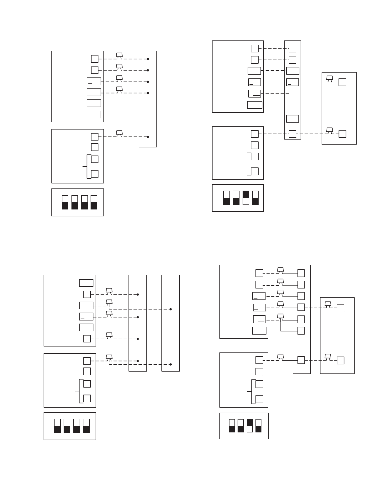
Table 1 — Model No. and Proper Wiring for Intended Applications
MODEL NO. APPLICATION FIG. NO.
Single-Speed AC with Single-Stage Furnace
Single-Speed AC with 2-Stage or Variable-Speed Furnace
1100
1200
1300
LEGEND
AC — Air Conditioner
HP — Heat Pump
Single-Speed AC with Typical Fan Coil (Single-Stage Heat Control)
Single-Speed AC with Variable-Speed Fan Coil
Single-Speed Packaged AC with Single-Stage Gas Furnace
Single-Speed Packaged AC with Single-Stage Electric Heat
Single-Speed AC with 2-Stage or Variable-Speed Furnace
Single-Speed AC with Typical Fan Coil (Dual-Stage Heat Control)
Single-Speed HP with Typical Fan Coil
Single-Speed AC with Variable-Speed Fan Coil
Single-Speed Packaged AC with 2-Stage Electric Heat
Single-Speed Packaged HP with Single-Stage Electric Heat
Single-Speed Packaged Heat Pump with 2-Stage Electric Heat
Single-Speed Packaged HP with Single-Stage Gas Furnace
2-Speed AC with Single-Stage Furnace
2-Speed AC with 2-Stage or Variable Speed Furnace
2-Speed AC with Typical Fan Coil
2-Speed HP with Single-Stage Furnace
2-speed HP with 2-Stage or Variable-Speed Furnace
2-Speed HP with Typical Fan Coil
2-Speed AC with Variable-Speed Fan Coil
2-Speed HP with Variable-Speed Fan Coil
Single-Speed HP with Variable-Speed Fan Coil and Special 3-Stage Electric Heat
2
3
4
5
6
7
8
9
10
11
12
13
14
15
16
17
18
19
20
21
22
23
24
3

MODEL 1100
THERMOSTAT
24 VAC HOT
FAN
HEAT STAGE 1
COOL STAGE 1
N/A
N/A
R
G
W/W1
Y/Y2
O/W2
Y1/W2
SINGLE-STAG E
FURNACE
R
G
W
Y
SINGLE-SPEED
AIR CONDITIONER
Y
MODEL 1100
THERMO
24 VAC HOT
FAN
COOL STAGE 1
HEAT STAGE 1
N/A
N/A
STAT
R
G
Y/Y2
W/W1
O/W2
Y1/W2
TYPICAL
FAN COIL
R
G
Y
W2
3
W
E
AIR CONDITIONER
*
SINGLE-SPEED
Y
24 VAC COMM
N/A
OUTDOOR
SENSOR
CONNECTION
ON
ABCD
OFF OFF OFF OFF
C
B
S1
S2
SUGGESTED DIP
SWITCH SETTINGS
C
See Note 1 on page 9.
C
Fig. 2 — Single-Speed Air Conditioner with
Single-Stage Furnace — Model 1100 Thermostat
MODEL 1100
THERMOSTAT
24 VAC HOT
FAN
HEAT STAGE 1
COOL STAGE 1
N/A
N/A
24 VAC COMM
N/A
OUTDOOR
SENSOR
CONNECTION
R
G
W/W1
Y/Y2
O/W2
Y1/W2
C
B
S1
S2
TWO-STAGE OR
VARIABLE-SPEED
FURNACE
R
G
W/W1
Y/Y2
W2
HUM
C
See Notes 1 and 6 on page 9.
SINGLE-SPEED
AIR CONDITIONER
Y
C
24 VAC COMM
N/A
OUTDOOR
SENSOR
CONNECTION
ON
ABCD
OFF OFF OFF OFF
C
B
S1
S2
SUGGESTED DIP
SWITCH SETTINGS
C
See Notes 1 and 7 on page 9.
* May not be present on equipment.
Fig. 4 — Single-Speed Air Conditioner with
Typical Fan Coil — Model 1100 Thermostat
(Single-Stage Heat Control)
MODEL 1100
THERMOSTAT EASY SELECT
24 VAC HOT
HEAT STAGE 1
N/A
FAN
N/A
COOL STAGE 1
24 VAC COMM
N/A
OUTDOOR
SENSOR
CONNECTION
Y1/W2
TERMINAL BOARD
R
W/W1 W1
O/W2
G G
Y/Y2 YY/Y2
C
B
S1
S2
DH
J1 JUMPER
R
J2 JUMPER
W2
Y1
O
C
See Notes 1 and 7 on page 9.
SINGLE-SPEED
AIR CONDITIONER
C
C
ON
SUGGESTED DIP
SWITCH SETTINGS
ABCD
OFF OFF OFF OFF
Fig. 3 — Single-Speed Air Conditioner with
2-Stage or Variable-Speed Furnace —
Model 1100 Thermostat
ON
SUGGESTED DIP
SWITCH SETTINGS
ABCD
OFF OFF OFF OFF
Fig. 5 — Single-Speed Air Conditioner with
Variable-Speed Fan Coil — Model 1100 Thermostat
4
MODEL 1100
THERMOSTAT
24 VAC HOT
FAN
HEAT STAGE 1
COOL STAGE 1
N/A
N/A
R
G
W/W1
Y/Y2
O/W2
Y1/W2
RED
GRN
WHT
YEL
SPLICE
BOX
MODEL 1200
THERMOSTAT
24 VAC HOT
FAN
HEAT STAGE 1
COOL STAGE 1
HEAT STAGE 2
N/A
R
G
W/W1
Y/Y2
O/W2
Y1/W2
TWO-STAGE OR
VARIABLE-SPEED
FURNACE
R
G
W/W1
Y/Y2
W2
HUM
SINGLE-SPEED
AIR CONDITIONER
Y
24 VAC COMM
N/A
OUTDOOR
SENSOR
CONNECTION
ON
ABCD
C
B
S1
S2
SWITCH SETTINGS
BRN
See Notes 1 and 9 on page 9.
SUGGESTED DIP
Fig. 6 — Single-Speed Packaged Air Conditioner
with Single-Stage Gas Furnace —
Model 1100 Thermostat
MODEL 1100
THERMOSTAT
N/A
FAN
HEAT STAGE 1
COOL STAGE 1
N/A
24 VAC HOT
Y1/W2
G
W/W1
Y/Y2
O/W2
R
GRN
WHT
YEL
RED
SPLICE
BOX
HEATER
CONTROL BOX
WHT
24 VAC COMM
N/A
OUTDOOR
SENSOR
CONNECTION
ON
ABCD
OFF OFF ON OFF
C
B
S1
S2
SUGGESTED DIP
SWITCH SETTINGS
C
See Note 2 on page 9.
Fig. 8 — Single-Speed Air Conditioner with
2-Stage or Variable-Speed Furnace —
Model 1200 Thermostat
MODEL 1200
THERMOSTAT
24 VAC HOT
FAN
HEAT STAGE 1
COOL STAGE 1
HEAT STAGE 2
N/A
R
G
W/W1
Y/Y2
O/W2
Y1/W2
TYPICAL
FAN COIL
R
G
W2
*
Y
W3
E
SINGLE-SPEED
AIR CONDITIONER
C
Y
24 VAC COMM
N/A
OUTDOOR
SENSOR
CONNECTION
ON
ABCD
OFF OFF OFF OFF
C
B
S1
S2
BRN
See Notes 1, 9, and 10 on page 9.
SUGGESTED DIP
SWITCH SETTINGS
Fig. 7 — Single-Speed Packaged Air Conditioner
with Single-Stage Electric Heat —
Model 1100 Thermostat
BRN
24 VAC COMM
N/A
OUTDOOR
SENSOR
CONNECTION
ON
ABCD
OFF OFF ON OFF
C
B
S1
S2
SUGGESTED DIP
SWITCH SETTINGS
C
C
See Notes 2 and 7 on page 9.
* May not be present on equipment.
Fig. 9 — Single-Speed Air Conditioner with
Typical Fan Coil — Model 1200 Thermostat
(Dual-Stage Heat Control)
5
 Loading...