

TOTALINE Gold P274-0100-C, Gold P274-0200-C, Gold P274-0300-C Owner's Manual
TOTA-
LINE 1c.eps
gold-1.pdf
OWNER’S
MANUAL
Non-Programmable
Residential
Thermostat
Part Numbers P274-0100-C, P274-0200-C, P274-0300-C
.
IMPORTANT: Read entire instructions before programming the thermostat.
GENERAL
Totaline® thermostats are wall-mounted, low-voltage thermostats which maintain room temperature by controlling the
operation of an HVAC (heating, ventilation and air conditioning) system. Separate heating and cooling set points and
auto-changeover capability allow occupied and unoccupied
programming for energy savings.
During power interruption the internal memory stores temperature and mode settings for an unlimited time. Batteries are
not required.
OPERATION
Thermostat Display —
ed in the top center of the thermostat. See Fig. 1. The following
information can be displayed on the screen:
• mode (OFF, HEAT, COOL, EHEAT, or AUTO)
• fan setting (ON or AUTO)
• auxiliary heat status (P274-0200-C, -0300-C only)
• room temperature
• desired temperature
• reset filter
• outdoor temperature (P274-0200-C, -0300-C only)
The thermostat display is locat-
Thermostat Buttons — The thermostat has buttons
which are used to change the set points of the thermostat and
set the thermostat modes. The buttons are accessible from
behind the thermostat cover. To access the buttons, pull on the
hinged thermostat cover. The buttons are: MODE, FAN, and
RESET FIL TER. See Fig. 1.
The UP and DOWN buttons are used to change the current,
desired temperature set point and to scroll through programming set points. The UP and DOWN buttons are located on the
front of the thermostat.
Setting Indoor Temperature Set Points
1. Press the UP or DOWN button one time. The LCD
(liquid crystal display) will illuminate and the curren t
temperature set point will be displayed. Next to the
temperature display, HEAT or COOL will be displayed. SET TEMP will appear above the temperature
display.
2. To change the temperature set point, continue to press
the UP or DOWN buttons until desired temperature is
reached. Press the MODE button to set temperature for
another setting (Heat or Cool).
3. The thermostat will automatically return to regular
operation within 5 seconds.
NOTE: The cool setting must be at least 2 degrees higher than
the heat setting for proper operation.
Fan Operation — The FAN button selects fan operation.
The fan can operate in either Fan ON or AUTO mode.
Press the FAN button to switch between fan ON or AUTO
mode. When the fan is set to ON, “FAN” is displayed in the
LCD on the thermostat. The fan will run continuously for improved air circulation while in the ON position.
When the fan is set to AUTO mode, the fan runs only as
needed to maintain indoor air temperature.
NOTE: The “FAN” indicator will not be displayed in the LCD
when thermostat is operating in AUTO mode.
Mode Operation — The Mode button selects the operat-
ing mode of the thermostat. Pressing the MODE button will
rotate the following options on the LCD: OFF, HEAT, COOL,
AUTO, and EHEAT (heat pump models only). The mode
for each selection will be displayed on the thermostat when
selected.
NOTE: If AUTO is selected, the thermostat will enter Heating
or Cooling mode based on the room temperature and the heating and cooling set points.
Display Outdoor Temperature — To display the
outdoor-air temperature on thermostats offering this feature,
simultaneously press the UP and DOWN buttons for twenty
seconds. The outdoor temperature will then be displayed on the
LCD.
NOTE: Two dashes “--” appearing on the LCD indicates that
the thermostat either does not have this feature installed or the
temperature sensor is not properly connected.
Reset Filter Display — The thermostat will display
“FILTER” on the LCD when it is time to change or clean the
filter.
After cleaning or changing the filter, press the RESET
FIL TER button to restart the timer and turn of f the indicator.
Auto Changeover Operation — The thermostat will
provide automatic changeover from Heating to Cooling mode
and Cooling to Heating mode when required. The thermostat
will automatically switch to maintain the desired temperature
setting. The thermostat does not need to be manually changed
from heating to cooling or cooling to heating operation.
Manufacturer reserves the right to
discontinue, or change at any time,
specifications or designs without notice
and without incurring obligations.
REPLACEMENT COMPONENTS DIVISION LITERATURE NUMBER P274-7SO
© CARRIER CORPORATION 2004 1106 9-04 REPLACES: 997-510011-19
PRINTED IN U.S.A. CATALOG NO. 570-352
Battery Changeout — If the installation requires the
usage of batteries, the batteries will require replacement every
12 months.
Open thermostat door and slide the battery compartment
door to the right. Remove two AA alkaline batteries. Install
two new AA alkaline batteries following the polarity markings
(+ / –) on the thermostat.
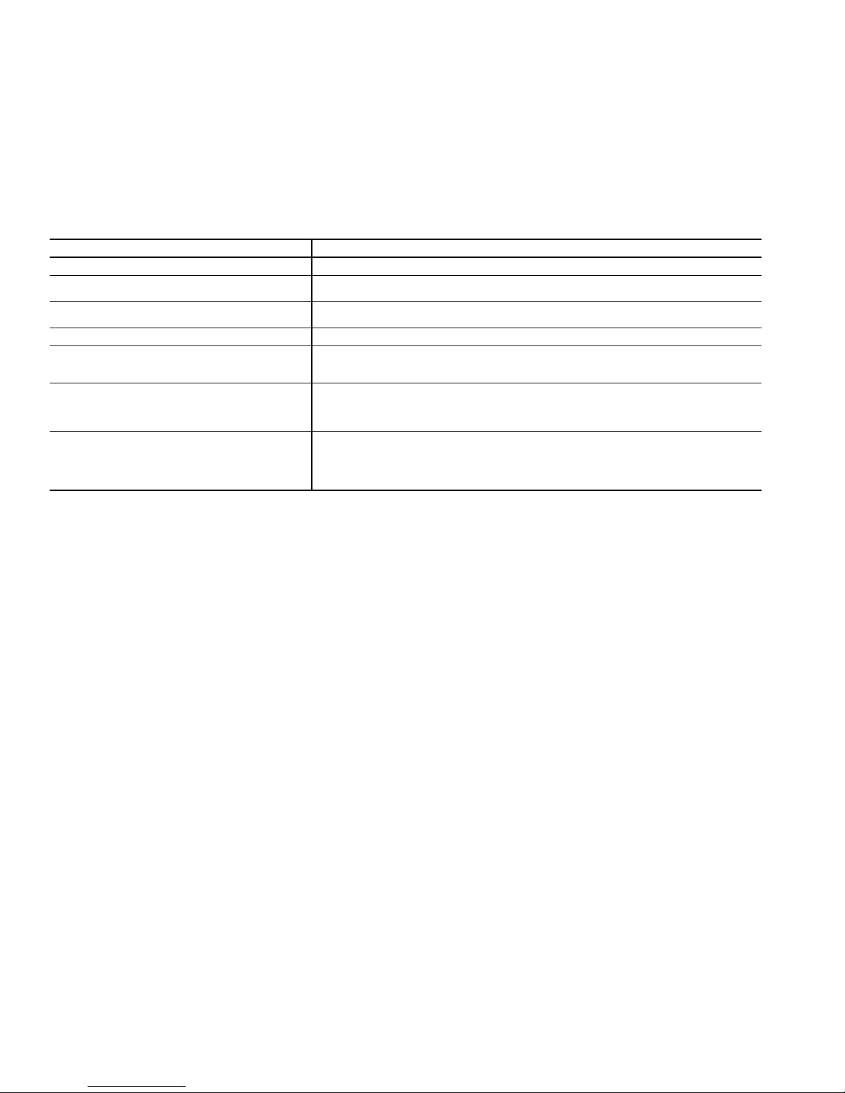
Table 1 — Error Codes
SYMPTOM WHAT TO CHECK
Blank LCD Check for 24 vac between R and C at terminal connections or battery.
"--" (2 dashes) on temperature display
"E2" on temperature display
"E3" on temperature display The outdoor temperature sensor is open, not connected, or shorted.
"SERVICE FILTER" on temperature display
Cooling will not come on
Heating will not come on
Temperature sensor reading out of range. Check sensor for damage. If recycling power
does not clear display, thermostat should be replaced.
Brownout condition or too low of voltage to thermostat. Double check wiring and check for
24 vac between R and C. E2 will clear 15 sec after proper voltage is restored.
After the selected number of hour of blower operation "FILTER" will display on LCD. This is
to remind the home owner to "check" the filter. Press RESET FILTER button to clear display
and reset timer to 0.
Select COOL mode. Set desired temperature to 10° F below room temperature. Simultaneously press FAN and INCREASE TEMPERATURE buttons to defeat timers. Check for
COOL ON icon and 24 vac at Y (first-stage) terminal. If present, thermostat is okay and
problem is with equipment or wiring. If not present, replace thermostat.
Select HEAT mode. Set desired temperature to 10° F above room temperature. Simultaneously press FAN and INCREASE TEMPERATURE buttons to defeat timers. Check for
HEAT ON and 24 vac at Y (first-stage) terminal (with heat pump) or W/W1 (with air conditioner) terminal. If present, thermostat is okay and problem is with equipment or wiring. If
not present, replace thermostat.
NOTE: If installation is hard-wired, batteries are not
required and will not need to be replaced.
Error Codes — If the thermostat displays “--”, “E2”,
“E3”, or “E4” in the LCD, an error is present. See Tabl e 1 for
error codes and descriptions.
2
 Loading...