

Product Training Content
Installer Settings manual

SYSTEM SETTINGS
Default Settings 3
Initiate Installer Settings 3
Installer Setting Options 4
INSTALLER SETTINGS
Indoor Equipment Type/Stages 7-8
Outdoor Equipment Type/Stages 9-10
Auto Allowed 11
Programmable or Non-Programmable 12
Fahrenheit or Celcius 13
Smart Recovery 14
Fan On with W 15
Reversing Valve 16
Indoor Temp Offset 17
Indoor Humidity Offset 18
TABLE OF CONTENTS
Auto Changeover 19
Remote Sensor 20
Cool Lockout 21
Time Between Fuel Types 22
Cycles Per Hour 23
Humidifier 24
Dehumidifier 25
Max Heat/Min Cool Set Point 26-27
Aux Heat Lockout 28
Heat Pump Lockout 29
Stage Delay 30
Forced Stage Up 31
Differential 32
Air Filter Reminder 33-34
System Setting Restore Defaults 35

2
2
SYSTEM SETTINGS

SYSTEM SETTING DEFAULTS
SYSTEM SETTINGS DEFAULT
Indoor Equip Type
Indoor Equip Stages
Outdoor Equip Type
Outdoor Equip Stages
Auto Allowed?
Prog or Non-Prog
Fahrenheit or Celsius
Smart Recovery
Fan On with W
Reversing Valve
Indoor Temp Offset
Indoor HUM Offset
Auto Changeover
Remote Sensor
Cool Lockout
Time B/W Fuel Types
Cycles per Hour
Humidifier
Dehumidifier
Max Heat Setpoint
Min Cool Setpoint
Aux Heat Lockout
HP Lockout
Stage Delay
Forced Stage Up
Differential
Air Filter Reminder
FURNACE
1
A/C
1
YES
PROG
°F
YES
YES
COOL
0°F
0%
30 MIN
NONE
55°F
15 MIN
4
NO
NO
88°F
52°F
OFF
OFF
10 MIN
30 MIN
0.5°F
3000 HRSFURNACE
3
INITIATE INSTALLER SETTINGS
4
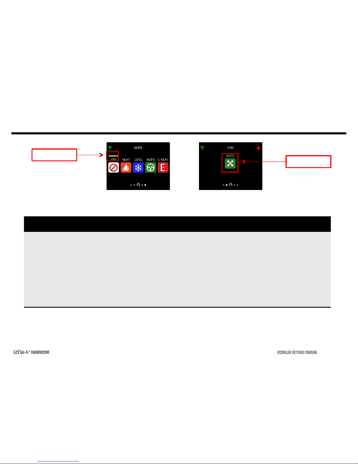
Off Mode
Selected
Press and Hold
5 Seconds
DEFINITION DEPENDENCIES FUNCTION
To invoke the “System Settings Screen” the end
user must first navigate to the “Mode Screen”
and then ensure that the Mode is set to Off and
then go to the “Fan Screen” and press and hold
the Fan Button for 5-seconds. Once this
sequence is completed, the “System Settings
Screen” screen will be displayed allowing the
end user (or installer) to make changes to
advanced settings on the thermostat.
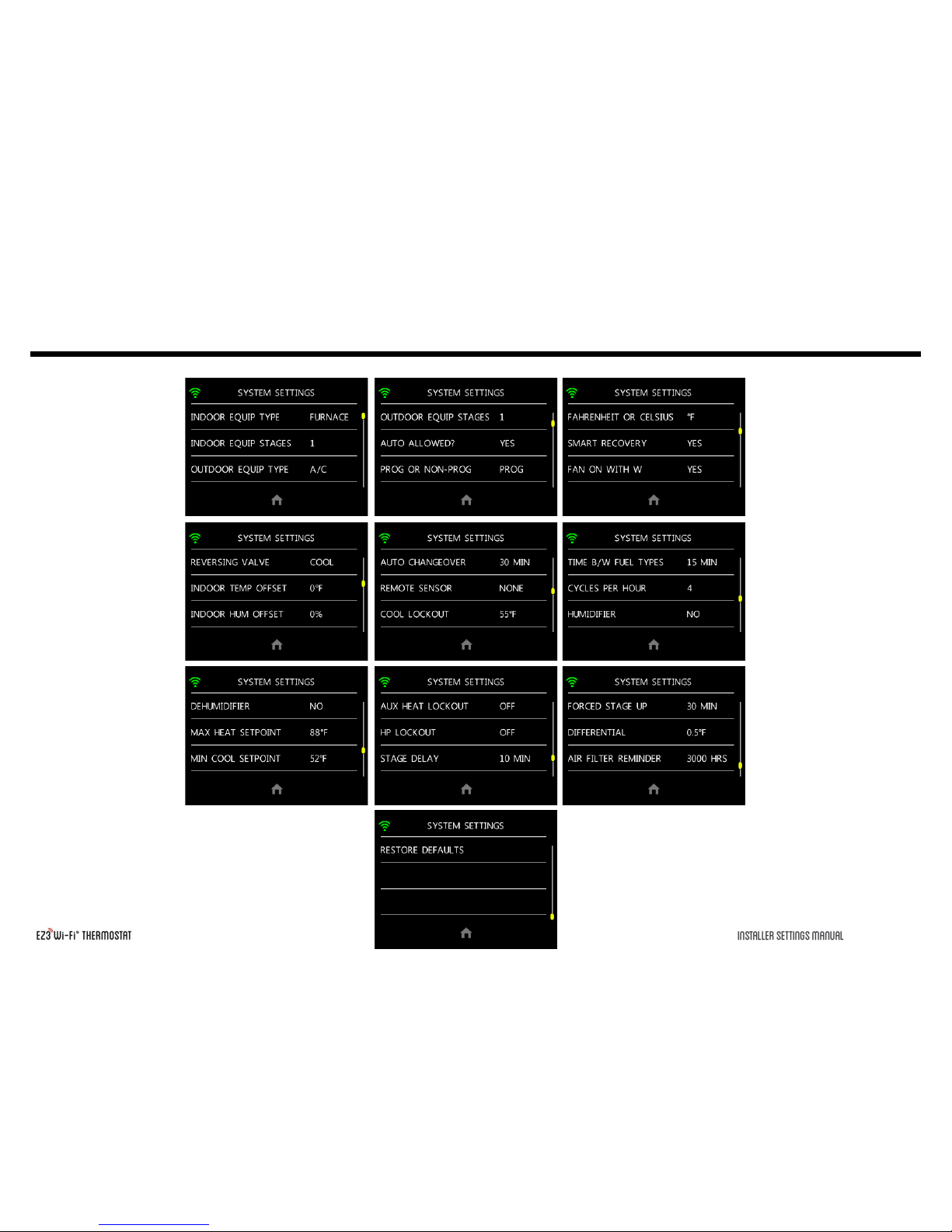
None Once the “System Settings Screen” is
displayed, the end user has the option to
“Up Swipe” and “Down Swipe” to navigate
through multiple advanced settings
options for the thermostat. The yellow
Row Indicator at the right side of these
screens indicates the location of the list of
advanced settings options and can also be
pushed upward or pulled downward to
navigate through the settings options.
INSTALLER SETTING OPTIONS
5

6
6 6
INSTALLER SETTINGS
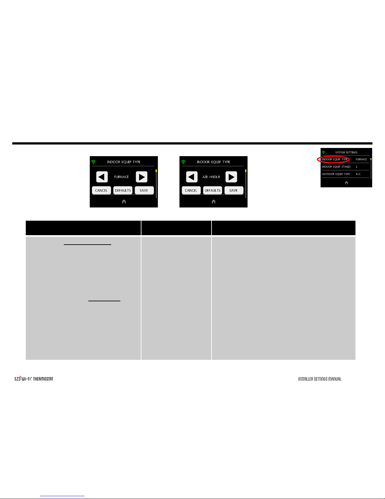
SETTINGS – INDOOR EQUIPMENT TYPE
7
DEFINITION DEPENDENCIES FUNCTION
Pressing the Indoor Equip Type field in
the “System Settings Screen” will invoke
the “Indoor Equip Type Screen” which
allows for selection of the type of indoor
equipment being used. Options for the
indoor equipment type include
FURNACE and AIR HNDLR. Once the
correct indoor equipment type is
selected, pressing the Save Button will
save the selection into non-volatile
memory.
None INDOOR EQUIPMENT — An indoor equipment type
must be chosen so that an airflow source is
available to the system operation. The two types of
indoor equipment defined for operation are a
FURNACE and an AIR HANDLER (sometimes also
referred to as a FAN COIL). The indoor equipment
is not required to have a heat source present, which
is selectable with the Indoor Equipment Stages
setting. If control of a PACKAGE UNIT is desired
and the PACKAGE UNIT has a natural or propane
heating source installed, the FURNACE option
should be selected.
If the INDOOR EQUIPMENT type of FURNACE is
chosen and the OUTDOOR EQUIPMENT type of
HP is chosen, then the defined DUAL FUEL
thermostat operation will be used for heating.
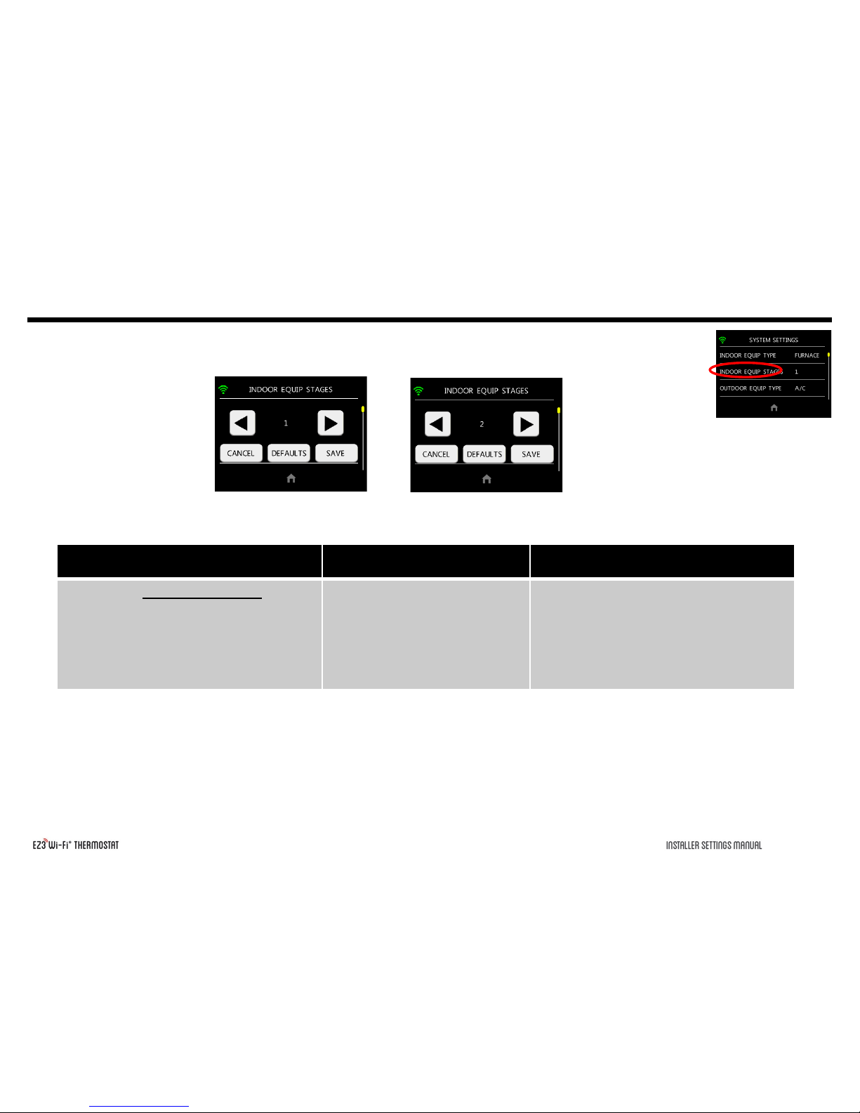
SETTINGS – INDOOR EQUIPMENT STAGES
8
DEFINITION DEPENDENCIES FUNCTION
Pressing the Indoor Equip Stages field in
the “System Settings Screen” will invoke
the “Indoor Equip Stages Screen” which
allows for selection of the number of
stages for the indoor equipment being
used from 0 to 2.
The option of “0” INDOOR
EQUIPMENT STAGES is only
available if the INDOOR
EQUIPMENT TYPE of AIR
HNDLR is selected
INDOOR EQUIPMENT STAGES — The
numbers of stages chosen defines the
number of gas heating stages or aux
heating stages that are present in the
indoor equipment.
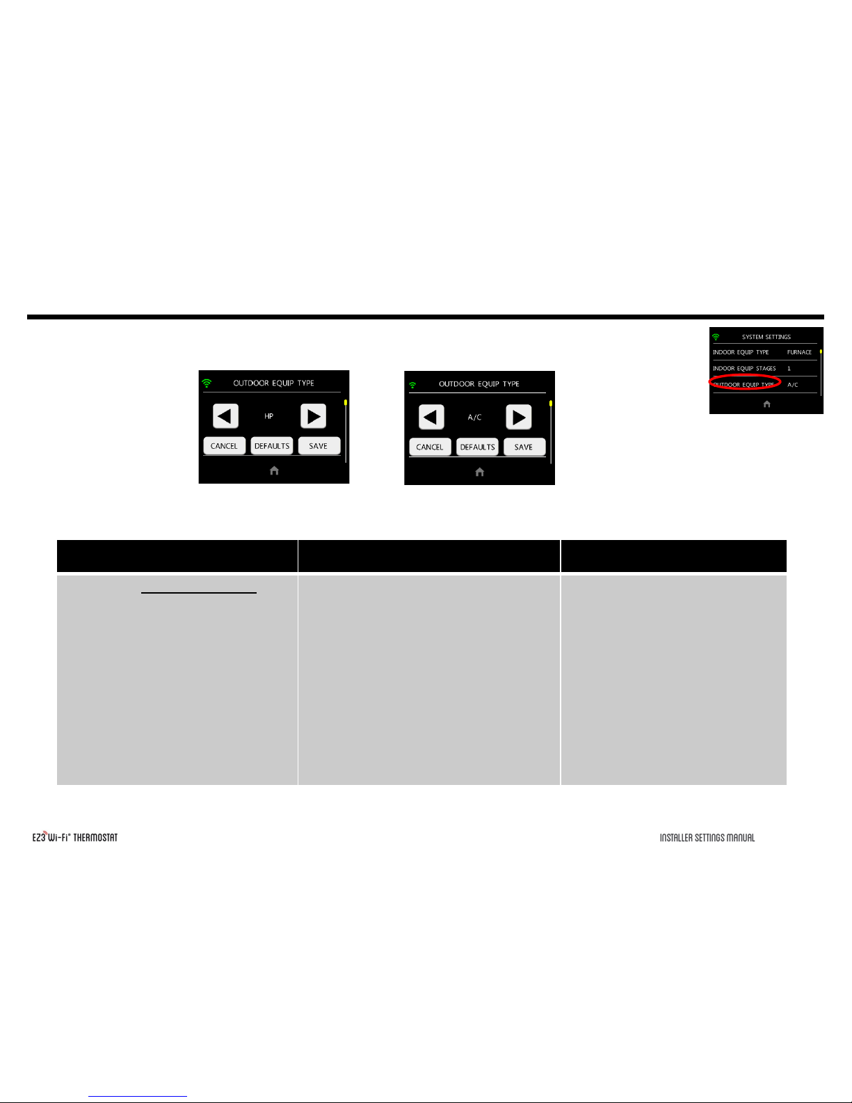
SETTINGS – OUTDOOR EQUIPMENT TYPE
9
DEFINITION DEPENDENCIES FUNCTION
Pressing the Outdoor Equip Type field
in the “System Settings Screen” will
invoke the “Outdoor Equip Type
Screen” which allows for selection of
the type of outdoor equipment being
used. Options for the outdoor
equipment type include NONE, HP
and A/C.
If NONE is chosen for the outdoor
equipment, then no cooling will be
available and the COOL MODE will be
disabled on the “Mode Screen”. The
OUTDOOR EQUIPMENT STAGES setting
will also be forced to a value of “0” if
NONE is selected for the outdoor
equipment type. The COOL TO
DEHUMIDIFY functionality would also be
disabled if the NONE is chosen for the
outdoor equipment type.
OUTDOOR EQUIPMENT — An
outdoor equipment type is not
required to be chosen and result in
a selection of NONE.
If the INDOOR EQUIPMENT type of
FURNACE is chosen and the
OUTDOOR EQUIPMENT type of
HP is chosen, then the defined
DUAL FUEL thermostat operation
will be used for heating.
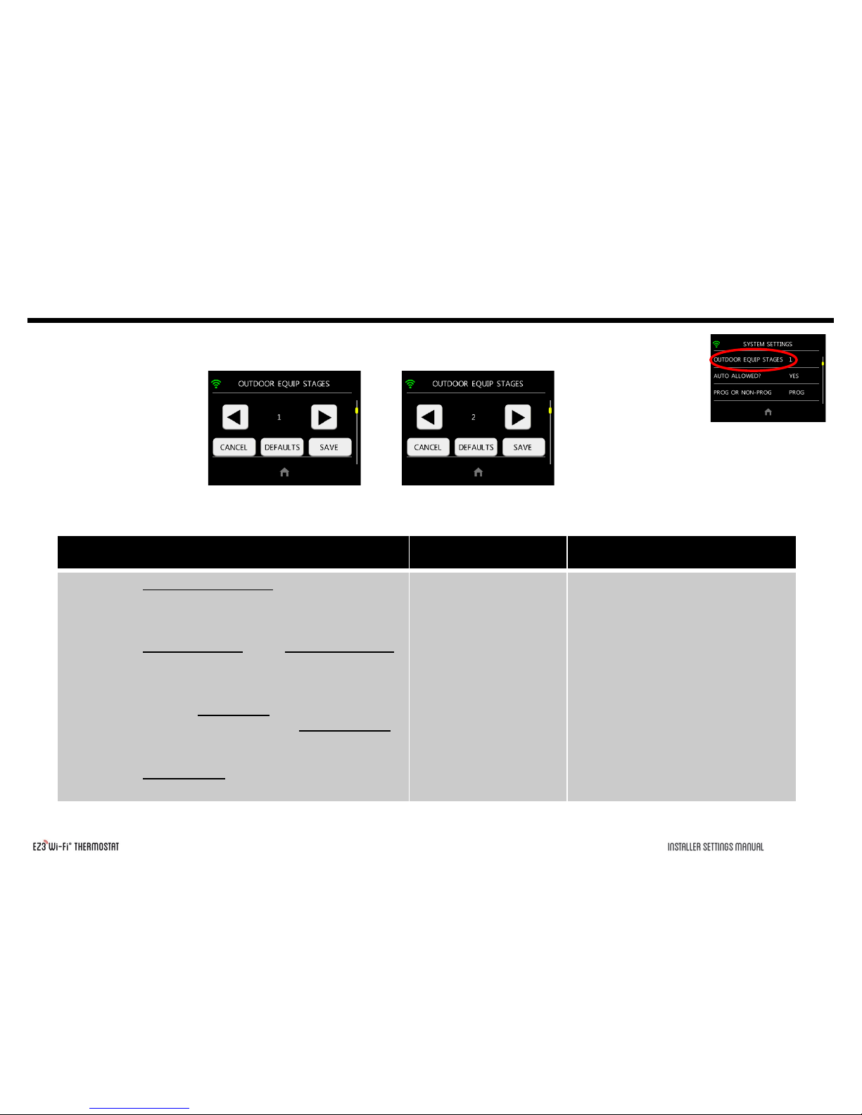
SETTINGS – OUTDOOR EQUIPMENT STAGES
10
DEFINITION DEPENDENCIES FUNCTION
Pressing the Outdoor Equip Stages field in the “System
Settings Screen” will invoke the “Outdoor Equip Stages
Screen” which allows for selection of the number of
stages for the outdoor equipment being used from 0 to 2.
Pressing the Left Arrow Button or the Right Arrow Button
will scroll through the available number of outdoor
equipment stages, which is displayed in the center of the
screen. Once the correct outdoor equipment stages are
selected, pressing the Save Button will save the selection
into non-volatile memory. Pressing the Defaults Button
will load the default outdoor equipment stages of “1” (the
user will still need to Save or Cancel this setting).
Pressing the Cancel Button will navigate back to the
“System Settings Screen”.
The option of “0”
OUTDOOR
EQUIPMENT STAGES
is only available if the
OUTDOOR
EQUIPMENT TYPE of
NONE is selected.
The numbers of stages chosen
defines the number of HP or A/C
cooling stages that are present in
the outdoor equipment. The
numbers of stages chosen also
defines the number of HP heating
stages that are present in the
outdoor equipment if the OUTDOOR
EQUIPMENT TYPE of HP is
selected.

SETTINGS – AUTO ALLOWED?
11
DEFINITION DEPENDENCIES FUNCTION
Pressing the Auto Allowed? field in the
“System Settings Screen” will invoke
the “Auto Allowed Screen” which
enables or disables the Auto Button on
the “Mode Screen”.
The AUTO ALLOWED feature is
only available if both a heating
source and a cooling source is
available (a Cool Only or Heat
Only system will not allow for
AUTO mode).
The AUTO ALLOWED feature is used to
enable and disable the ability of the AUTO
MODE feature. AUTO MODE feature allows
the thermostat to automatically switch from
heating mode to cooling mode to maintain
the conditioned temperature between the
heating and cooling setpoints.
No= Disabled
“Auto Mode”

SETTINGS – PROG OR NON-PROG
12
DEFINITION DEPENDENCIES FUNCTION
Pressing the PROG or
NON-PROG field in the
“System Settings
Screen” will invoke the
“PROG OR NON-PROG
Screen” which allows the
thermostat to operate as
a non-programmable
(simplified) thermostat or
a programmable
thermostat.
If the NON-PROG
functionality is chosen
then the PLAY/PAUSE
button and associated
text will not be available
on the “Setpoint Screen”.
If the NON-PROG
functionality is chosen
then the “Settings –
Program Screen” will not
be available.
Choosing the non-programmable mode for the thermostat allow the
thermostat to run in a simplified mode that will satisfy heating or
cooling setpoints based on the setpoint value and mode chosen.
Operating the thermostat in a programmable mode allows the end
user to setup heating and cooling setpoints for 4 periods of each
day of the seven days of the week. The thermostat has default
heating and cooling setpoints. Changing the heating and cooling
setpoints and the transition times for the 4 periods with each day is
achieved only thorough the APP developed specifically for the
thermostat. The program heating and cooling setpoints and
transition times for the 4 periods can be viewed in the “Settings –
Program Screen” on the thermostat.

SETTINGS – FAHRENHEIT OR CELSIUS
13
DEFINITION DEPENDENCIES FUNCTION
Pressing the Fahrenheit or Celsius field in the
“System Settings Screen” will invoke the
“Fahrenheit or Celsius Screen” which allows
the thermostat to use either the Fahrenheit or
Celsius scale to display temperature and
setpoints.
None This feature allows the thermostat temperatures to be
displayed using either the Fahrenheit scale or the
Celsius scale

SETTINGS – SMART RECOVERY
14
DEFINITION DEPENDENCIES FUNCTION
Pressing the Smart Recovery
field in the “System Settings
Screen” will invoke the “Smart
Recovery Screen” which
enables or disables the smart
recovery algorithm.
The SMART
RECOVERY feature is
only available if the
thermostat is configured
as a programmable
thermostat.
The Smart Recovery feature transitions the conditioned
space from one programmable temperature period to the
next so that the conditioned space temperature matches the
programmable temperature set point at the start of each
programmable time period. This means, for example, that if
the 4th period of the day temperature setting is lower than
the 3rd period that precedes it, then the thermostat will start
cooling down the space before the beginning of the
scheduled 4th period of the day.

SETTINGS – FAN ON WITH W
15
DEFINITION DEPENDENCIES FUNCTION
Pressing the Fan On with W field in the
“System Settings Screen” will invoke the
“Fan On with W Screen” which enables or
disables the functionality to turn on the Fan
(G output) with any W heating demand
output.
None The Fan On With W feature is used to supply a fan
output demand as soon as a W1 or W2 output demand
is active.

SETTINGS – REVERSING VALVE
16
DEFINITION DEPENDENCIES FUNCTION
Pressing the Reversing Valve field in the
“System Settings Screen” will invoke the
“Reversing Valve Screen” which enables the
reversing valve output (O/B) to either be
activated for heat pump heating or heat
pump cooling demand.
This functionality is
only used in
operational logic if a
Heat-Pump is chosen
as the Outdoor
Equipment Type.
This functionality defines whether the ON state of
the reversing valve is used for Heating or Cooling.
When the ON state of the reversing valve is used
for Cooling, the signal is typically referred to as a
“O” demand. When the ON state of the reversing
valve is used for Heating, the signal is typically
referred to as a “B” demand.

SETTINGS – INDOOR TEMP OFFSET
17
DEFINITION DEPENDENCIES FUNCTION
Pressing the Indoor Temp Offset field in the
“System Settings Screen” will invoke the
“Indoor Temp Offset Screen” which will offset
the displayed thermostat room temperature
from -5° to +5°, adjustable in 1° increments.
None This functionality offers the end user the
convenience of matching the actual sensed
temperature to a different perceived temperature or
a different temperature measuring device.

SETTINGS – INDOOR HUM OFFSET
18
DEFINITION DEPENDENCIES FUNCTION
Pressing the Indoor HUM Offset field in the
“System Settings Screen” will invoke the
“Indoor HUM Offset Screen” which will offset
the displayed thermostat humidity reading
from -5% to +5%, adjustable in 1%
increments.
None This functionality offers the end user the
convenience of matching the actual sensed
humidity to a different perceived humidity or a
different humidity measuring device.

SETTINGS – AUTO CHANGEOVER
19
DEFINITION DEPENDENCIES FUNCTION
Pressing the Auto Changeover field in the “System Settings
Screen” will invoke the “Auto Changeover Screen” which will
allow a time choice from 5 minutes to 30 minutes for the auto
changeover functionality, adjustable in 5 minute increments.
Pressing the Defaults Button will load the default setting of
“30 MIN” (the user will still need to Save or Cancel this
setting). Pressing the Cancel Button will navigate back to
the “System Settings Screen”.
None This functionality sets up the minimum
time between switching from heat-tocool or from cool-to-heat demands
when operating in Auto Mode. The
timer begins when the Minimum OFF
Timer expires.

SETTINGS – REMOTE SENSOR
20
DEFINITION DEPENDENCIES FUNCTION
Pressing the Remote Sensor
field in the “System Settings
Screen” will invoke the
“Remote Sensor Screen” which
enables the remote sensor
connection to be used for the
indoor temperature, the
outdoor temperature, or not to
be used.
None This functionality determines whether the Remote Sensor
hardware input (JP102) is not used (NONE), is used for the
outdoor temperature sensing (OUTDOOR) or used for the indoor
room temperature sensing (INDOOR). If the Remote Sensor is
set to NONE or INDOOR, the outdoor temperature will be
acquired via Wi-Fi through the server (based on the geolocation
of the phone/tablet used to connect the thermostat to a router or
based on the ISP location if a PC is used to connect the
thermostat to a router). The outdoor temperature will not be
available if the thermostat is not connected to Wi-Fi and the
OUTDOOR option is not selected for the Remote Sensor. Note: A
pigtail to wire the remote sensor is included in the package.

SETTINGS – COOL LOCKOUT
21
DEFINITION DEPENDENCIES FUNCTION
Pressing the Cool Lockout field in
the “System Settings Screen” will
invoke the “Cool Lockout Screen”
which will allow a temperature
choice from OFF to 55°F to 80°F
for the cool lockout functionality,
adjustable in 5° increments.
If there is not a valid
outdoor temperature
available then this
feature will be set to
the OFF setting.
This functionality is used to hold off the cooling equipment
demands if the outdoor air temperature is below the chosen
value. A System Event warning will occur if the mode and
indoor temperature dictate that there should be a cooling
demand and the outdoor temperature value is holding off
this demand.

SETTINGS – TIME BETWEEN FUEL TYPES
22
DEFINITION DEPENDENCIES FUNCTION
Pressing the Time Between Fuel Types field in the
“System Settings Screen” will invoke the “Time
Between Fuel Types Screen” which will allow a time
choice from 10 minutes to 25 minutes for the time
between fuel choices functionality, adjustable in 5
minute increments.
If there are not
multiple fuel types,
this logic will not be
used.
This functionality is used to set the
minimum time limit between switching from
one fuel type to another (other staging rules
may also be in effect).

SETTINGS – CYCLES PER HOUR
23
DEFINITION DEPENDENCIES FUNCTION
Pressing the Cycles per Hour field in the “System
Settings Screen” will invoke the “Cycles per Hour
Screen” which will allow a numeric choice from 2 to
6 for the CYCLE TIMER functionality, adjustable in
numerical increments of 2.
None Based on the selection of 2, 4, or 6 cycles
per hour, this timer is set to 30, 15 or 10
minutes. This time must elapse from the
start of one cycle before another cycle can
start. It serves to impose the cycles per
hour limits.

SETTINGS – HUMIDIFIER
24
DEFINITION DEPENDENCIES FUNCTION
Pressing the Humidifier field
in the “System Settings
Screen” will invoke the
“Humidifier Screen” which
enables or disables the
HUMIDIFIER CONTROL
functionality.
The HUMIDIFIER CONTROL functionality is
not available if a HP is selected for the Outdoor
Equipment type, because the O/B functionality
( output) is shared with the humidifier output.
This functionality is also not available if 3Stages of Cooling is selected for the Outdoor
Equipment stages, because the Y3 functionality
( output) is also shared with the humidifier
output.
In humidification operation, the humidifier
will be on if there is humidity demand and
any heating equipment is on. The
output is a 24VAC output only (sourced
from “R”) and must be isolated with a
relay at the indoor equipment if 120VAC
is needed to interface to a humidifier unit.

SETTINGS – DEHUMIDIFIER
25
DEFINITION DEPENDENCIES FUNCTION
Pressing the Dehumidifier
field in the “System Settings
Screen” will invoke the
“Dehumidifier Screen” which
enables or disables the
COOL TO DEHUMIDIFY
function.
Pressing the Dehumidifier field
in the “System Settings Screen”
will invoke the “Dehumidifier
Screen” which enables or
disables the COOL TO
DEHUMIDIFY function.
The cool to dehumidify selection tells the system to
operate the compressor, within limits, when there is a
dehumidification demand even if there is no cooling
demand. The limits are that the system may overcool up
to 2°F, but no more, while attempting to satisfy a
dehumidification demand. Within this 2°F range, there is
an additional balance between overcooling and humidity
satisfaction.

SETTINGS – MAX HEAT SET POINT
26
DEFINITION DEPENDENCIES FUNCTION
Pressing the Max Heat Setpoint field in
the “System Settings Screen” will invoke
the “Max Heat Setpoint Screen” which
will allow a temperature choice from 50°F
to 88°F for the max heat setpoint
functionality, adjustable in 1°F
increments.
None This feature is used to choose the maximum heating
setpoint that is available on the Heat Setpoint Wheel
and the maximum heating setpoint that can be used for
the program schedule.

SETTINGS – MIN COOL SET POINT
27
DEFINITION DEPENDENCIES FUNCTION
Pressing the Min Cool Setpoint field in
the “System Settings Screen” will invoke
the “Min Cool Setpoint Screen” which will
allow a temperature choice from 52°F to
90°F for the min cool setpoint
functionality, adjustable in 1°F
increments.
None This feature is used to choose the minimum cooling
setpoint that is available on the Cool Setpoint Wheel
and the minimum cooling setpoint that can be used for
the program schedule.

SETTINGS – AUX HEAT LOCKOUT
28
DEFINITION DEPENDENCIES FUNCTION
Pressing the Aux Heat Lockout
field in the “System Settings
Screen” will invoke the “Aux Heat
Lockout Screen” which will allow
a temperature choice from OFF to
5°F to 55°F for the aux heat
lockout functionality, adjustable in
5°F increments.
The Aux Heat Lockout functionality
is not available (and will be set to
the OFF setting) with the Outdoor
Equipment Type of NONE or AC
selected, because the aux heat
lockout functionality needs HP
heating to operate. This
functionality is also not available if a
valid outdoor temperature is not
available (resulting in a System
Event notification).
If the auxiliary heat lock out temperature setting
is not OFF and the outdoor air temperature is
greater than auxiliary heat lock out
temperature, then the Aux Heat (W1 & W2)
outputs shall not turn on.

SETTINGS – HEAT PUMP LOCKOUT
29
DEFINITION DEPENDENCIES FUNCTION
Pressing the HP Lockout
field in the “System Settings
Screen” will invoke the “HP
Lockout Screen” which will
allow a temperature choice
from OFF to 5°F to 55°F for
the aux heat lockout
functionality, adjustable in
5°F increments.
The HP Lockout functionality is
not available with the Outdoor
Equipment Type of NONE or AC
selected, because the aux heat
lockout functionality needs HP
heating to operate. This
functionality is also not available if
a valid outdoor temperature is not
available (resulting in a System
Event notification).
If a setting of OFF is selected, The heating equipment
cycle shall always start with the heat pump regardless
of the outdoor air temperature. If a lockout
temperature is selected and the outdoor air
temperature is less than the selected temperature, the
heating cycle is started with the AUX Heat source. If
the outdoor air temperature is equal to or greater than
the selected temperature, the heating cycle is started
with the heat pump. If the outdoor temperature is not
available, all heating cycles shall start with compressor
heat.

SETTINGS – STAGE DELAY
30
DEFINITION DEPENDENCIES FUNCTION
Pressing the Stage Delay field in
the “System Settings Screen” will
invoke the “Stage Delay Screen”
which will allow a time choice
from 2 minutes to 15 minutes for
the stage delay functionality,
adjustable in 1 minute
increments.
Multiple heating stages or
multiple cooling stages must
exist for this feature to be
used.
The minimum amount of time the current stage must
be energized before staging up to the next stage of
capacity. If the system demand is greater than three
degrees then this configuration is ignored for the
current heating or cooling cycle because the staging
timers are canceled to allow full equipment capacity to
meet the large demand.

SETTINGS – FORCED STAGE UP
31
DEFINITION DEPENDENCIES FUNCTION
Pressing the Forced Stage Up
field in the “System Settings
Screen” will invoke the “Forced
Stage Up Screen” which will allow
a time choice from OFF to 10
minutes to 120 minutes for the
forced stage up timer
functionality, adjustable in 10
minute increments.
Multiple heating stages or
multiple cooling stages must
exist for this feature to be
used.
If time in a current demanded stage reaches the forced
stage up selected time, the thermostat will stage up to
the next available stage of capacity (even if differential
demand is not met).

SETTINGS – DIFFERENTIAL
32
DEFINITION DEPENDENCIES FUNCTION
Pressing the Differential field in
the “System Settings Screen” will
invoke the “Differential Screen”
which will allow a temperature
choice from 0.3°F to 2.0°F for the
differential functionality,
adjustable in 0.1°F increments.
None This functionality specifies the required difference between the
current room temperature and the setpoint before demand is
initiated. This value is additive for each additional stage of
equipment being demanded. (e.g. A chosen Differential value
of 0.5°F requires 0.5 degree difference between setpoint and
room temperature before first stage is turned on. Then a value
of 1.0 degree of difference between setpoint and room
temperature before second stage is turned on.)

SETTINGS – AIR FILTER REMINDER
33
DEFINITION DEPENDENCIES FUNCTION
Pressing the Air Filter Reminder
field in the “System Settings
Screen” will invoke the “Air Filter
Reminder Screen” which will
allow a setting for equipment
runtime hours choice from OFF to
500 HRS to 15,000 HRS for the
stage delay functionality,
adjustable in 100 hour
increments.
None This functionality defines a chosen number of hours before a
System Event will occur to remind the homeowner to change the
indoor air filter. A System Event will not occur to remind the
homeowner to change the indoor air filter if the OFF setting is
selected. Decrements to the timer will happen each hour of total
equipment runtime is accumulated. Minute counts within each
hour are not stored in non-volatile memory, so a power reset will
clear out the minutes within each hour of run time. The Filter
Reset Reminder hour timer value is stored in non-volatile
memory.

SETTINGS – AIR FILTER REMINDER
34
DEFINITION DEPENDENCIES
FUNCTION
Pressing the Air Filter Reminder
field in the “System Settings
Screen” will invoke the “Air Filter
Reminder Screen” which will
allow a setting for equipment
runtime hours choice from OFF to
500 HRS to 15,000 HRS for the
stage delay functionality,
adjustable in 100 hour
increments.
None This functionality defines a chosen number of hours before a
System Event will occur to remind the homeowner to change
the indoor air filter. A System Event will not occur to remind the
homeowner to change the indoor air filter if the OFF setting is
selected. Decrements to the timer will happen each hour of
total equipment runtime is accumulated. Minute counts within
each hour are not stored in non-volatile memory, so a power
reset will clear out the minutes within each hour of run time.
The Filter Reset Reminder hour timer value is stored in nonvolatile memory.

SYSTEM SETTING RESTORE DEFAULTS
SYSTEM SETTINGS DEFAULT
Indoor Equip Type
Indoor Equip Stages
Outdoor Equip Type
Outdoor Equip Stages
Auto Allowed?
Prog or Non-Prog
Fahrenheit or Celsius
Smart Recovery
Fan On with W
Reversing Valve
Indoor Temp Offset
Indoor HUM Offset
Auto Changeover
Remote Sensor
Cool Lockout
Time B/W Fuel Types
Cycles per Hour
Humidifier
Dehumidifier
Max Heat Setpoint
Min Cool Setpoint
Aux Heat Lockout
HP Lockout
Stage Delay
Forced Stage Up
Differential
Air Filter Reminder
FURNACE
1
A/C
1
YES
PROG
°F
YES
YES
COOL
0°F
0%
30 MIN
NONE
55°F
15 MIN
4
NO
NO
88°F
52°F
OFF
OFF
10 MIN
30 MIN
0.5°F
3000 HRSFURNACE
35
SCREEN
SEGMENT
DEFINITION FUNCTION
Restore Defaults Restore Defaults Screen will allow the
user to reset all system settings back to
factory default values. Pressing and
holding the 5 Button will count down to
initiate the restore defaults operation.
After holding the button down for 5seconds all system settings will be
returned to factory default values.
Pressing the Cancel Button will
navigate back to the “System Settings
Screen”.
This functionality
is used to restore
all Installer Setup
– System Settings
to their default
values.
 Loading...