

Page 1
2104349-001– rev. AB
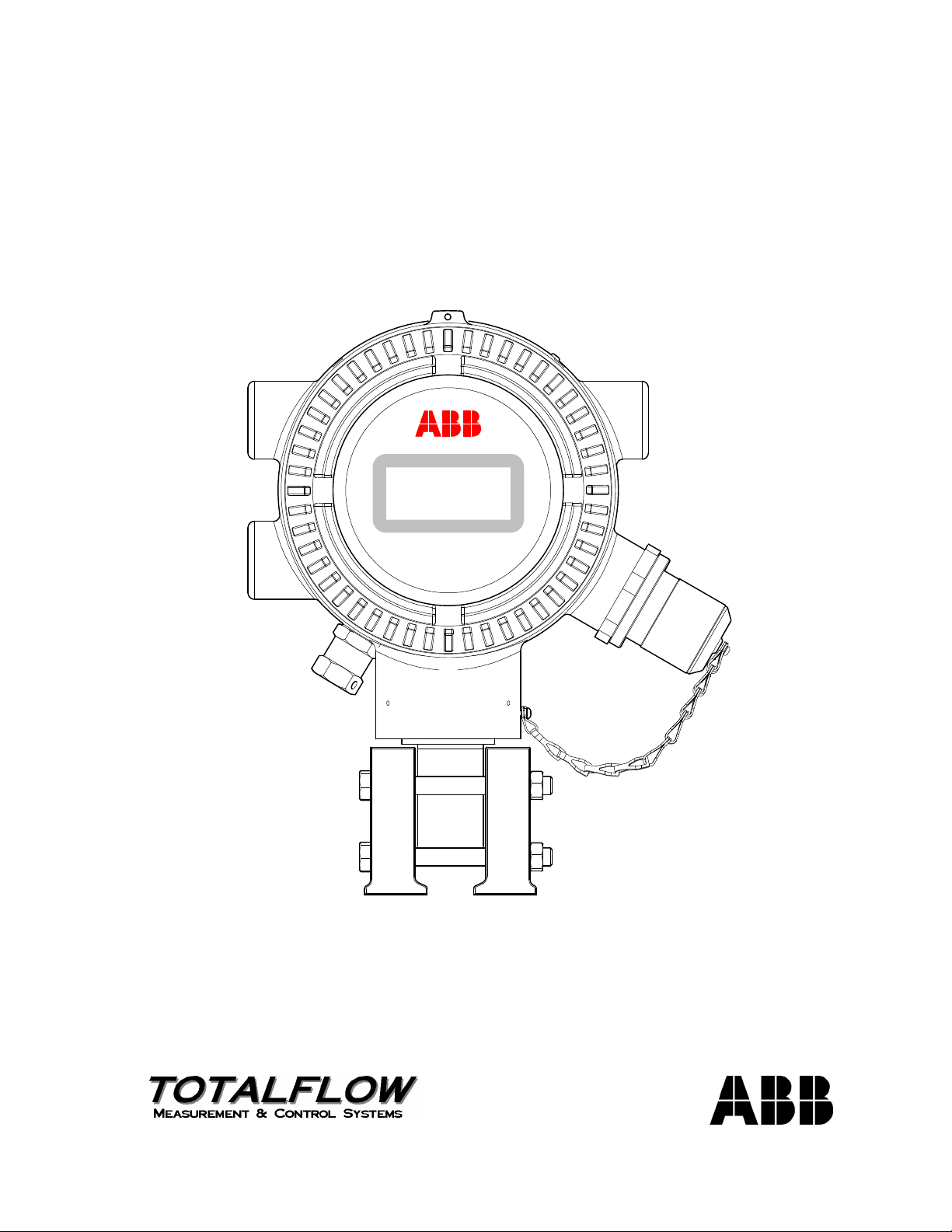
XSeriesG4 6200/6201EX Flow Computer
User’s Manual
XFCG4EX
Page 2

Intellectual Property & Copyright Notice
©2011 by ABB Inc., Totalflow (“Owner”), Bartlesville, Oklahoma 74006, U.S.A. All rights reserved.
Any and all derivatives of, including translations thereof, shall remain the sole property of the Owner,
regardless of any circumstances.
The original US English version of this manual shall be deemed the only valid version. Translated
versions, in any other language, shall be maintained as accurately as possible. Should any
discrepancies exist, the US English version will be considered final.
Notice: This publication is for information only. The contents are subject to change without notice and
should not be construed as a commitment, representation, warranty, or guarantee of any method,
product, or device by Owner.
Inquiries regarding this manual should be addressed to ABB Inc., Totalflow Products, Technical
Communications, 7051 Industrial Blvd., Bartlesville, Oklahoma 74006, U.S.A.
Page 3

TABLE OF CONTENTS
INTRODUCTION ......................................................................................................XI
Organization & Style................................................................................................... xi
Chapter Descriptions.................................................................................................. xi
Getting Help ............................................................................................................... xi
Before Calling ...............................................................................................................xi
Key Symbols ..............................................................................................................xii
Safety Practices and Precautions ..............................................................................xii
Safety Guidelines .......................................................................................................xiii
Safety First ................................................................................................................. xiii
Equipment Markings...................................................................................................xiv
Grounding the Product ...............................................................................................xiv
Operating Voltage.......................................................................................................xiv
Danger From Loss of Ground..................................................................................... xiv
Safe Equipment ..........................................................................................................xiv
Fuse Replacement .....................................................................................................xiv
1.0 SYSTEM DESCRIPTION ............................................................................ 1–1
1.1 Overview...................................................................................................... 1–1
1.1.1 Capabilities .................................................................................................. 1–2
1.1.2 Functionality ................................................................................................ 1–3
1.1.3 Flow Computer Calculations ....................................................................... 1–3
1.1.4 Log Period Records..................................................................................... 1–4
1.1.5 Display Function .......................................................................................... 1–5
1.1.6 Display Annunciators................................................................................... 1–6
1.2 G4 EX Computer Hardware......................................................................... 1–7
1.2.1 G4 EX Enclosure ......................................................................................... 1–8
1.2.2 G4 EX Main Processor Board ................................................................... 1–10
1.2.3 G4 EX Termination Board .........................................................................1–12
1.2.4 Explosion Proof Multivariable Transducer (EXIMV) .................................. 1–18
1.2.5 Display Assembly ...................................................................................... 1–20
1.2.6 Resistive Temperature Detector (RTD)..................................................... 1–21
1.2.7 6270 Optional Equipment Unit (OEU) ....................................................... 1–22
1.2.8 Solar Panel ................................................................................................ 1–22
1.2.9 Lithium Battery........................................................................................... 1–23
1.3 G4 EX Application Licensing ..................................................................... 1–24
1.3.1 Credit Key (USB) ....................................................................................... 1–25
1.4 Laptop Computer Running PCCU32 ......................................................... 1–25
1.5 Local G4 EX Connectors ........................................................................... 1–26
1.5.1 RS-232 Serial PCCU Cable (Round Military Cable) ................................. 1–26
1.5.2 PCCU32 USB Connection......................................................................... 1–27
1.5.3 Bluetooth Connectivity............................................................................... 1–28
1.5.4 Network Connectivity (Dynamic IP with Router) ....................................... 1–28
2.0 INSTALLATION.......................................................................................... 2–1
2.1 Unpacking and Inspection ........................................................................... 2–1
2.1.1 Unpacking.................................................................................................... 2–1
i
Page 4

2.1.2 Inspection.....................................................................................................2–1
2.1.3 Damaged Components ................................................................................2–1
2.2 2” Pole Mount Installation............................................................................ 2–1
2.2.1 Type A..........................................................................................................2–2
2.2.2 Type B..........................................................................................................2–3
2.2.3 Type C..........................................................................................................2–4
2.2.4 Manifold Input Lines.....................................................................................2–5
2.2.5 Standard RTD Probe Installation .................................................................2–6
2.2.6 Explosion Proof RTD Probe Assembly ........................................................2–8
2.2.7 6270 Optional Equipment Unit (OEU) Installation .....................................2–10
2.2.8 Battery Pack Installation ............................................................................2–12
2.2.9 Lithium Battery Installation.........................................................................2–13
2.2.10 Solar Panel Installation ..............................................................................2–14
2.2.11 AC Charging Unit Installation.....................................................................2–16
2.2.12 Uninterrupted Power Supply (UPS) to the G4 EX .....................................2–19
3.0 G4 EX START-UP....................................................................................... 3–1
3.1 Overview ..................................................................................................... 3–1
3.2 PCCU32 Installation and Setup................................................................... 3–1
3.2.1 Step-by-Step Instructions.............................................................................3–1
3.3 Establishing Local Communication ............................................................. 3–2
3.3.1 Connecting to a Local Port via a RS-232 Cable ..........................................3–2
3.3.2 Connecting To Local USB Port ....................................................................3–3
3.3.3 Setup of the G4 EX for Bluetooth Connectivity............................................3–5
3.3.4 Setup of the G4 EX for Ethernet Connectivity .............................................3–7
3.4 Setting Up the G4 EX ................................................................................ 3–12
3.4.1 Date/Time...................................................................................................3–12
3.4.2 Station ID ...................................................................................................3–13
3.4.3 Location......................................................................................................3–13
3.4.4 Security System .........................................................................................3–13
3.5 Application Licensing Credit Key............................................................... 3–23
3.5.1 Credit Key Driver Installation .....................................................................3–23
3.5.2 Access/View the Credit Key with PCCU32 7.0 (or later) ...........................3–23
3.5.3 Adding Credits to the Credit Key by Telephone.........................................3–25
3.5.4 Transferring Credits to the G4 EX from the Credit Key .............................3–26
3.5.5 Transferring Credits to the Credit Key from the G4 EX .............................3–27
3.6 G4 EX Configuration ................................................................................. 3–28
3.6.1 Contact Hour ..............................................................................................3–28
3.6.2 Log Period..................................................................................................3–29
3.6.3 Volume Calculation Period.........................................................................3–29
3.6.4 Calculated Method .....................................................................................3–29
3.6.5 Super Compressibility Calculation (Fpv)....................................................3–30
3.6.6 Constants ...................................................................................................3–31
3.6.7 Alarm Limits ...............................................................................................3–32
3.6.8 Reset Volume.............................................................................................3–33
3.7 Start Up the G4 EX.................................................................................... 3–33
3.7.1 Putting the G4 EX On Line.........................................................................3–33
3.7.2 Setting G4 EX Temperature Calculation....................................................3–33
ii
Page 5

3.8 G4 EX Standard Displays.......................................................................... 3–34
3.8.1 Program Display ........................................................................................ 3–34
4.0 G4 EX MAINTENANCE .............................................................................. 4–1
4.1 Overview...................................................................................................... 4–1
4.1.1 Maintenance Support ..................................................................................4–1
4.1.2 How to Use This Chapter ............................................................................4–1
4.1.3 Cleanliness .................................................................................................. 4–1
4.1.4 Front Mounted LCD ..................................................................................... 4–1
4.1.5 Returning Parts for Repair........................................................................... 4–1
4.2 Backing Up Configuration Files ................................................................... 4–1
4.2.1 Step-by-Step Instructions ............................................................................ 4–2
4.3 Restoring Configuration Files ...................................................................... 4–2
4.3.1 Step-by-Step Instruction .............................................................................. 4–2
4.4 Performing a Warm Boot ............................................................................. 4–2
4.4.1 Hardware Warm Boot.................................................................................. 4–2
4.4.2 Software Warm Boot ................................................................................... 4–3
4.5 Performing a Cold Boot ............................................................................... 4–4
4.5.1 Hardware Cold Boot .................................................................................... 4–4
4.5.2 Software Cold Boot...................................................................................... 4–5
4.6 Changing the G4 EX Clock.......................................................................... 4–6
4.6.1 Clock Change Not Crossing an Hour Boundary.......................................... 4–6
4.6.2 Forward Clock Change Crossing an Hourly Boundary ............................... 4–6
4.6.3 Backward Clock Change Crossing an Hourly Boundary............................. 4–6
4.7 Replacing the G4 EX Battery Pack............................................................. 4–6
4.7.1 Step-by-Step Instructions ............................................................................ 4–7
4.8 Replacing the G4 EX Board ........................................................................4–8
4.8.1 Step-by-Step Instructions ............................................................................ 4–9
4.9 Replacing the G4 EX Termination Board ..................................................4–11
4.9.1 Step-by-Step Instructions .......................................................................... 4–12
4.10 Replacing the Liquid Crystal Display (LCD) Board.................................... 4–13
4.10.1 Step-by-Step Instructions .......................................................................... 4–14
4.11 Replacing the Lithium Battery.................................................................... 4–14
4.11.1 Step-by-Step Instructions .......................................................................... 4–15
4.12 Replacing the Transducer (EXIMV)........................................................... 4–15
4.12.1 Step-by-Step Instructions .......................................................................... 4–16
4.13 Calibration .................................................................................................4–18
4.13.1 Required Test Equipment.......................................................................... 4–18
4.13.2 Hold Mode ................................................................................................. 4–19
4.13.3 Static Pressure (SP) Calibration Checks................................................... 4–19
4.13.4 Differential Pressure (DP) Calibration Checks .......................................... 4–21
4.13.5 Calibrating Static Pressure (SP)................................................................ 4–22
4.13.6 Calibrating Differential Pressure (DP) ....................................................... 4–24
4.14 Onboard I/O Calibration Overview............................................................. 4–25
4.14.1 Hold Mode ................................................................................................. 4–25
4.14.2 Calibrating Onboard Analog Inputs ........................................................... 4–25
iii
Page 6

4.14.3 Onboard Pulse and Digital Inputs ..............................................................4–26
4.15 Zero Transducer........................................................................................ 4–27
4.15.1 Static Pressure...........................................................................................4–27
4.15.2 Differential Pressure ..................................................................................4–27
4.16 RTD Calibration and Bias.......................................................................... 4–27
4.16.1 Step-by-Step Instructions...........................................................................4–28
4.16.2 Calibrating RTD Temperature Bias............................................................4–29
4.17 Changing the Orifice Plate ........................................................................ 4–29
4.17.1 Taking Meter Run Out of Service (Simplex Fitting) ...................................4–29
4.17.2 Leaving Meter Run In Service Procedure (Senior Fitting) .........................4–30
5.0 TROUBLESHOOTING ................................................................................ 5–1
5.1 Overview ..................................................................................................... 5–1
5.1.1 Troubleshooting Support..............................................................................5–1
5.1.2 Visual Alarm Codes .....................................................................................5–1
5.1.3 Sleep Mode ..................................................................................................5–1
5.1.4 Solar Panel...................................................................................................5–1
5.1.5 Communication ............................................................................................5–1
5.2 Troubleshooting Visual Alarm Codes .......................................................... 5–2
5.2.1 Troubleshooting a Blank LCD Screen .........................................................5–4
5.2.2 Troubleshooting a Low Lithium Alarm (LL) ..................................................5–4
5.2.3 Troubleshooting a Analog to Digital Failure Alarm (AD)..............................5–5
5.2.4 Resistive Temperature Detector (RTD) Continuity Test ..............................5–6
5.2.5 RTD Current Source (Resistive) Test ..........................................................5–6
5.2.6 RTD Impedance Test...................................................................................5–7
5.3 Power Troubleshooting ............................................................................... 5–8
5.3.1 Overview ......................................................................................................5–8
5.3.2 Power Supply Test.......................................................................................5–8
5.3.3 Charger Circuit Test.....................................................................................5–9
5.3.4 Solar Panel Charging System Test............................................................5–10
5.3.5 AC Charging System Unit Test..................................................................5–12
5.3.6 Auxiliary Equipment Isolation Test.............................................................5–12
5.3.7 Sleep Mode ................................................................................................5–13
5.3.8 Reset Procedures ......................................................................................5–14
5.4 Communications Troubleshooting............................................................. 5–14
5.4.1 Overview ....................................................................................................5–14
5.4.2 Setting Up Communication ........................................................................5–16
5.4.3 Transceiver Supply Voltage Test...............................................................5–16
5.4.4 6270 OEU Supply Voltage Test.................................................................5–16
5.4.5 Transceiver Check .....................................................................................5–17
5.4.6 Termination Board Supply Voltage Test ....................................................5–17
5.4.7 RS-232 Communication.............................................................................5–18
5.4.8 RS-232 Termination Board Test ................................................................5–18
5.4.9 RS-232 OEU Termination Strip Test..........................................................5–19
5.4.10 RS-485 Communication Test.....................................................................5–20
5.4.11 RS-485 Termination Board Test ................................................................5–21
5.4.12 RS-485 OEU Termination Strip Test..........................................................5–22
APPENDIX A I/O DAUGHTER CARD ....................................................... A–1
iv
Page 7

A.1 Materials Supplied in the Upgrade Kit .........................................................A–1
A.2 I/O Daughter Card Specifications ................................................................A–1
A.3 Installation ...................................................................................................A–1
A.3.1 Upgrading the Flash ....................................................................................A–2
A.3.2 Unit Operating Status Shut Down Instructions............................................A–3
A.3.3 Internal PCCU Connector Disassembly (If Installed) ..................................A–3
A.3.4 I/O Daughter Card Installation.....................................................................A–4
A.3.5 Internal PCCU Connector Reassembly (If Previously Installed) .................A–5
A.3.6 Implementation ............................................................................................A–6
APPENDIX B 4–20 MILLIAMP TRANSMITTERS....................................B–11
B.1 Powering 4–2- Milliamp Transmitters ........................................................B–11
B.2 Example 1..................................................................................................B–13
B.3 Example 2..................................................................................................B–13
B.4 Conclusion.................................................................................................B–13
APPENDIX C G4 EX MODBUS REGISTER MAPS ...................................C–1
C.1 System Application Registers..................................................................... C–1
C.1.1 System Application Register Notes............................................................ C–3
C.2 Display Application Registers..................................................................... C–5
C.2.1 Display Application Register Notes ............................................................ C–7
C.3 Alarm System Application Registers .......................................................... C–8
C.3.1 Alarm System Application Register Notes................................................ C–10
C.4 Holding Registers ..................................................................................... C–11
C.4.1 Holding Register Notes............................................................................. C–12
C.5 Reports Application Registers .................................................................. C–13
C.5.1 Reports Register Notes............................................................................ C–14
C.6 Operations Application Registers ............................................................. C–14
C.6.1 Operations Application Register Notes .................................................... C–24
C.7 Communication Application Registers...................................................... C–28
C.7.1 Communication Application Register Notes............................................. C–30
C.8 Safety Controller Application Registers.................................................... C–32
C.8.1 Array Types .............................................................................................. C–32
C.8.2 General Registers..................................................................................... C–33
C.8.3 Safety Controller Register Notes.............................................................. C–34
C.9 6200EX IOS Application Registers........................................................... C–35
C.9.1 IOS UINT32 Registers.............................................................................. C–35
C.9.2 IOS UINT16 Registers.............................................................................. C–36
C.9.3 IOS Byte Registers................................................................................... C–36
C.9.4 IOS Float Registers .................................................................................. C–37
C.9.5 IOS AI Struct and Calibration Point Registers.......................................... C–39
C.9.6 IOS Term Board Raw Counts Registers – Uint16.................................... C–41
C.9.7 Engine EEProm Registers (16 Bytes per page) – Strings........................ C–41
C.9.8 Term Board FE Ram Registers (64 Bytes Per Page) Strings .................. C–41
C.9.9 IOS II2C Descriptor Registers – Strings................................................... C–41
C.9.10 IOS SPI Port Data Registers .................................................................... C–41
v
Page 8

C.9.11 IOS SPI Port Statistics Registers – Uint 32 .............................................. C–41
C.9.12 IOS String Registers .................................................................................C–42
C.9.13 IOS Daughter CardByte Registers............................................................ C–42
C.9.14 IOS Daughter Card UINT16 Registers ..................................................... C–42
C.9.15 IOS Daughter Card UINT32 Registers ..................................................... C–43
C.9.16 IOS Daughter Card Float Registers .......................................................... C–43
C.9.17 IOS Daughter Card FE Ram Registers (A2) (64 Bytes Per Page)-StringsC–43
C.9.18 IOS Daughter Card FE Ram Registers (A4) (64 Bytes Per Page)-StringsC–43
C.9.19 Term Board AI/DO Usage ......................................................................... C–43
C.10 AGA-3 Measurement Tube Application Registers.....................................C–44
C.10.1 AGA-3 Tube Byte Registers...................................................................... C–44
C.10.2 Tube 16-Bit Integer Registers ................................................................... C–48
C.10.3 Tube 32-Bit Integer Registers ................................................................... C–49
C.10.4 Tube Floating Point Registers................................................................... C–49
C.10.5 Tube Register Cross References.............................................................. C–52
C.10.6 Tube String Registers ...............................................................................C–53
C.10.7 Tube Last Calculation Period Analysis Registers, Floating Point ............. C–53
C.10.8 Tube Archive Registers – Read Only ....................................................... C–54
C.10.9 Tube Log Period Registers .......................................................................C–54
C.10.10 Tube Daily Registers................................................................................. C–55
C.10.11 Tube Event Registers ...............................................................................C–57
C.10.12 AGA-3 Tube Registers.............................................................................. C–57
C.10.13 AGA-3 Float Registers .............................................................................. C–58
C.10.14 AGA-3 String Registers............................................................................. C–60
C.10.15 AGA-3 Int32 Registers .............................................................................. C–60
C.11 AGA-7 Tube Application Register .............................................................C–61
C.11.1 Tube Byte Registers ................................................................................. C–61
C.11.2 Tube 16-Bit Integer Registers ................................................................... C–64
C.11.3 Tube 32-Bit Integer Registers ................................................................... C–66
C.11.4 Tube Floating Point Registers................................................................... C–66
C.11.5 Tube Register Cross Reference ............................................................... C–69
C.11.6 Tube String Registers ...............................................................................C–70
C.11.7 Tube Last Calculation Period Analysis Registers, Floating Point ............. C–70
C.11.8 Tube Archive Registers, Read Only.......................................................... C–71
C.11.9 Tube Daily Registers................................................................................. C–72
C.11.10 Tube Event Registers ...............................................................................C–73
C.11.11 AGA-7 Tube Byte Registers...................................................................... C–74
C.11.12 AGA-7 Float Registers .............................................................................. C–75
C.11.13 AGA-7 String Registers............................................................................. C–77
C.11.14 AGA-7 Int32 Registers .............................................................................. C–77
C.12 XMV Interface Application Registers .........................................................C–78
C.12.1 XMV Application Register Notes............................................................... C–85
C.13 Therms Master Application Registers........................................................C–86
C.13.1 Therms Master Btu Byte Registers ........................................................... C–86
C.13.2 Therms Master Btu Integer Registers ....................................................... C–87
C.13.3 Therms Master Btu Float Registers ..........................................................C–88
C.13.4 Therms Master Stream 1 Float Registers ................................................. C–90
C.13.5 Therms Master Stream 2 Float Registers ................................................. C–91
vi
Page 9

C.13.6 Therms Master Stream 3 Float Register .................................................. C–92
C.13.7 Therms Master Stream 4 Float Registers ................................................ C–94
C.13.8 Therms Master Btu Var Integer Registers................................................ C–95
C.13.9 Therms Master Btu Var Int32 Registers ................................................... C–95
C.13.10 Therms Master Slave Data Trigger Registers .......................................... C–96
C.13.11 Therms Master Current Stream Float Registers ...................................... C–96
C.13.12 Therms Master Slave Var Integer Registers ............................................ C–97
C.13.13 Therms Master Stream Time String Registers......................................... C–98
C.13.14 Therms Master Slave Var Integer Registers ............................................ C–98
C.14 Therms Display Registers ........................................................................ C–98
C.14.1 Therms Staus Btu Integer Registers ........................................................ C–98
C.14.2 Therms Status Float Registers ................................................................. C–99
C.14.3 Therms Stream SN Int32 Registers ....................................................... C–100
C.14.4 Therms Master Component Xref Index Registers .................................. C–100
C.14.5 Therms Master Btu Byte Registers ........................................................ C–101
C.14.6 Therms Master Component Xrefed Index Registers.............................. C–101
C.14.7 Therms Slave Var Modbus Address Registers ...................................... C–102
C.14.8 Therms Slave Var Modbus Address Registers ...................................... C–102
C.14.9 Therms Interface Control Get Request Registers .................................. C–103
C.14.10 Therms Master Int32 Registers .............................................................. C–103
C.14.11 Therms Slave Stream 1 Float Registers ................................................ C–103
C.14.12 Therms Slave Stream 2 Float Registers ................................................ C–104
C.14.13 Therms Slave Stream 3 Float Registers ................................................ C–104
C.14.14 Therms Master Slave Stream 4 Float Registers .................................... C–105
C.14.15 Therms Master Slave Analysis Trend File.............................................. C–106
C.15 Therms Slave Application Registers....................................................... C–107
C.15.1 Therms Slave Float Registers ................................................................ C–107
C.15.2 Therms Slave String Registers............................................................... C–109
C.15.3 Therms Slave Int32 Registers ................................................................ C–109
C.15.4 Therms Slave Stream 1 Float Registers ................................................ C–109
C.15.5 Therms Slave Stream 2 Float Registers ................................................ C–110
C.15.6 Therms Slave Stream 3 Float Registers ................................................ C–111
C.15.7 Therms Slave Stream 4 Float Registers ................................................ C–111
C.15.8 Therms Slave Analysis Trend File.......................................................... C–112
vii
Page 10

TABLE OF FIGURES
Figure 1–1 Typical G4 EX Installation.................................................................................................1–2
Figure 1–2 Liquid Crystal Display (LCD) and Indicators.....................................................................1–6
Figure 1–3 G4 EX Enclosure ..............................................................................................................1–9
Figure 1–4 G4 EX Enclosure Left Side ...............................................................................................1–9
Figure 1–5 G4 EX Enclosure Right Side...........................................................................................1–10
Figure 1–6 G4 EX Main Processor Board.........................................................................................1–11
Figure 1–7 G4 EX Termination Board...............................................................................................1–13
Figure 1–8 Typical DI Point Schematic.............................................................................................1–14
Figure 1–9 DI Connection Example ..................................................................................................1–15
Figure 1–10 Typical DO Point Schematics .......................................................................................1–16
Figure 1–11 DO Connection Example ..............................................................................................1–17
Figure 1–12 Typical AI Point Schematic ...........................................................................................1–17
Figure 1–13 AI Example Connections ..............................................................................................1–18
Figure 1–14 Explosion Proof Multivariable Transducer (EXIMV) .....................................................1–19
Figure 1–15 Liquid Crystal Display (LCD) Assembly........................................................................1–20
Figure 1–16 Explosion Proof Resistive Temperature Detector.........................................................1–21
Figure 1–17 Optional Communication Enclosure .............................................................................1–22
Figure 1–18 Solar Panel – Typical Installation..................................................................................1–23
Figure 1–19 RS-232 Local Communication Cable ...........................................................................1–27
Figure 1–20 USB Local Communication Cable ................................................................................1–27
Figure 1–21 Ethernet Communication Cable....................................................................................1–28
Figure 1–22 Ethernet Connectivity Diagram .....................................................................................1–29
Figure 2–1 Type A Installation Configuration......................................................................................2–3
Figure 2–2 Type B Installation Configuration......................................................................................2–4
Figure 2–3 Type C Installation Configuration......................................................................................2–5
Figure 2–4 G4 EX EXIMV Ports..........................................................................................................2–6
Figure 2–5 Thermowell Installation into the Meter Run ......................................................................2–7
Figure 2–6 RTD Probe Wiring.............................................................................................................2–8
Figure 2–7 Explosion Proof RTD Overview ........................................................................................2–8
Figure 2–8 Explosion Proof RTD Disassembled.................................................................................2–9
Figure 2–9 RTD Probe Wiring...........................................................................................................2–10
Figure 2–10 6270 OEU Pipe Mounting Installation...........................................................................2–11
Figure 2–11 6270 OEU Wall Mount Installation................................................................................2–12
Figure 2–12 6270 OEU Enclosure ....................................................................................................2–13
Figure 2–13 Lithium Battery..............................................................................................................2–14
Figure 2–14 Solar Panel Installation .................................................................................................2–15
Figure 2–15 AC Charger Installed ....................................................................................................2–17
Figure 2–16 AC Charger Outlet Box Installation...............................................................................2–18
Figure 2–17 AC Charger Inside the Conduit Enclosure....................................................................2–19
Figure 2–18 G4 EX to UPS...............................................................................................................2–19
Figure 3–1 System Setup Screen .......................................................................................................3–2
Figure 3–2 Windows Found New Hardware Wizard...........................................................................3–3
viii
Page 11

Figure 3–3 Specific Location Selection Window ................................................................................3–4
Figure 3–4 Specify Location for USB Driver (Totalflow.inf)................................................................ 3–4
Figure 3–5 System Setup - Bluetooth ................................................................................................ 3–6
Figure 3–6 Select a Bluetooth Device Dialog Box.............................................................................. 3–6
Figure 3–7 System Setup Dialog Box - Bluetooth.............................................................................. 3–7
Figure 3–8 Network Tab ..................................................................................................................... 3–8
Figure 3–9 Communication Setup...................................................................................................... 3–8
Figure 3–10 System Setup Window ................................................................................................... 3–9
Figure 3–11 Windows Desktop Shortcut Dialog Box........................................................................ 3–10
Figure 3–12 Network Tab ................................................................................................................. 3–11
Figure 3–13 System Setup ............................................................................................................... 3–12
Figure 3–14 Station Setup Tab......................................................................................................... 3–14
Figure 3–15 Security Setup Dialog Box ........................................................................................... 3–15
Figure 3–16 WinCCU32 Edit a Device ID Dialog Box...................................................................... 3–15
Figure 3–17 Role Administration Menu Path.................................................................................... 3–16
Figure 3–18 Security Editor Dialog Box ........................................................................................... 3–17
Figure 3–19 Roles Dialog Box.......................................................................................................... 3–17
Figure 3–20 User Name and Password Dialog Box......................................................................... 3–18
Figure 3–21 System Setup Dialog Box ............................................................................................ 3–19
Figure 3–22 Send Role Based Access Control File Dialog Box....................................................... 3–19
Figure 3–23 Totalflow-TCP Setup Tab............................................................................................. 3–20
Figure 3–24 Login Dialog Box .......................................................................................................... 3–21
Figure 3–25 System Setup Dialog Box ............................................................................................ 3–21
Figure 3–26 Security Log Tab .......................................................................................................... 3–22
Figure 3–27 Credit Key License Utility ............................................................................................. 3–24
Figure 3–28 Credit Key License Utility – Status ............................................................................... 3–24
Figure 3–29 Application Credit Key Entry Screen ............................................................................ 3–25
Figure 3–30 Application Credit Verification Codes........................................................................... 3–26
Figure 3–31 App Licensing Tab........................................................................................................ 3–27
Figure 3–32 Transfer to Credit Key .................................................................................................. 3–28
Figure 4–1 Reset Button Location...................................................................................................... 4–3
Figure 4–2 Lithium Battery Connector................................................................................................ 4–5
Figure 4–3 6270 OEU Configuration .................................................................................................. 4–7
Figure 4–4 G4 EX Front End Exploded View ..................................................................................... 4–8
Figure 4–5 Termination Board............................................................................................................ 4–9
Figure 4–6 G4 EX Board .................................................................................................................. 4–10
Figure 4–7 G4 EX Board Secondary Component Side.................................................................... 4–11
Figure 4–8 G4 EX Back End Exploded View ...................................................................................4–12
Figure 4–9 Termination Board Secondary Component Side ........................................................... 4–13
Figure 4–10 EXIMV Installation Overview........................................................................................ 4–16
Figure 4–11 G4 EX with Block Manifold........................................................................................... 4–17
Figure 4–12 Calibration Diagram...................................................................................................... 4–21
Figure 4–13 RTD Calibration Screen ............................................................................................... 4–28
ix
Page 12

Figure 5–1 Troubleshooting Flowchart ...............................................................................................5–2
Figure 5–2 Liquid Crystal Display and Indicators................................................................................5–3
Figure 5–3 Power Supply – G4 EX Termination Board ......................................................................5–4
Figure 5–4 G4 EX Termination Board.................................................................................................5–9
Figure 5–5 6270 OEU Charger Regulator ........................................................................................5–11
Figure 5–6 Current Measurement Troubleshooting Cable ...............................................................5–13
Figure 5–7 Communication Troubleshooting Flow Chart .................................................................5–15
Figure 5–8 OEU Termination Strip....................................................................................................5–20
LIST OF TABLES
Table 1—1 XFC Family Genealogy ....................................................................................................1–1
Table 1—2 Typical G4 EX Display Options ........................................................................................1–5
Table 1—3 Default Annunciator Locations .........................................................................................1–6
Table 1—4 G4 EX Status and Alarm Description ...............................................................................1–7
Table 1—5 G4 EX Main Processor Board Specifications.................................................................1–11
Table 1—6 Explosion Proof EXIMV Specifications...........................................................................1–19
Table 1—7 Standard RTD Probes ....................................................................................................1–21
Table 1—8 Standard Thermowells ...................................................................................................1–21
Table 3—1 Configurable Calculation Factors ...................................................................................3–29
Table 3—2 Fpv Analysis Data ..........................................................................................................3–30
Table 3—3 Gas Orifice Constants ....................................................................................................3–31
Table 3—4 Alarm Limits....................................................................................................................3–32
Table 3—5 G4 EX Displayed Items ..................................................................................................3–34
Table 4—1 Calibration Configurable Parameters .............................................................................4–18
Table 5—1 Visual Alarm Codes..........................................................................................................5–3
Table 5—2 Specifications for Solar Panels.......................................................................................5–10
Table 5—3 RS-232 Field Wiring on the G4 EX Termination Board..................................................5–18
Table 5—4 RS-485 Field Wiring on the G4 EX Termination Board..................................................5–21
x
Page 13

INTRODUCTION
This manual is designed to provide an experienced flow meter technician with the
requirements necessary to install, set up and operate a Totalflow XFC
6200/6201EX.
Organization & Style
Each of the chapters in this manual presents information in an organized and
concise manner. Readers are able to look at the headings and receive a broad
picture of the content without reading every word. Also, there are overviews at the
beginning of each chapter that provides the user with an idea of what is in the
chapter and how it fits into the overall manual.
Chapter Descriptions
Chapter Name Description
1 System Description
2 Installation
3 G4 EX Startup
4
5 Troubleshooting
Apdx. A I/O Daughter Card
Apdx. B
Apdx. C
G4 EX
Maintenance
4-20 Milliamp
Transmitters
G4 EX Modbus
Register Maps
G4
Provides a description of the G4 EX system
components and specifications.
Includes unpacking and detailed procedures
for set up and installation.
Provides the user with a tutorial on how to get
a newly installed G4 EX system up and
running.
Provides instructions on how to remove and
replace major modules.
Provides a description of the G4 EX front
panel error messages and provides a
troubleshooting chart on how to correct most
problems.
Instructions for the installation of the I/O
daughter card.
Provides in-depth information regarding the
powering of 4-20mA transmitter.
Provides a listing of all valid Modbus registers.
Getting Help
Before Calling
Totalflow takes pride in the ongoing support provided to customers. When
purchasing a product, users receive documentation which should answer their
questions; however, Totalflow Technical Support provides an 800 number as an
added source of information.
If requiring assistance, call:
USA: (800) 442-3097 International: 001-918-338-4888
• Know the Totalflow model and serial number. Serial numbers can
be found on a plate located on each unit.
xi
Page 14
Key Symbols
• Be prepared to give the customer service representative a detailed
description of the problem.
• Note any alarms or messages as they appear.
• Prepare a written description of the problem.
• Know the software version, board and optional part numbers.
The following symbols are used frequently in the manual. These are intended to
catch the eye and draw attention to important information.
Intended to draw attention to useful information or to clarify a
statement made earlier.
Intended to draw attention to a fact that may be useful or helpful
in understanding a concept.
Intended to draw attention to a statement that might keep the
user from making a mistake, keep the user from destroying
equipment or parts or keep the user from creating a situation that
could cause personal injury if caution is not used. Please refer to
the Safety Practices and Precautions section for additional
information.
Intended to draw attention to a statement regarding the likelihood
of personal injury or fatality that could result from improper
access or techniques used while working in hazardous locations.
Please refer to the Safety Practices and Precautions section for
additional information.
Safety Practices and Precautions
This manual contains information and warnings which have to be followed by the
user to ensure safe operation and to retain the product in a safe condition.
Installation, maintenance and repairs should only be performed by a trained and
qualified technician. Please refer to the certification drawings shipped with this unit
for specific guidelines. Extra copies of the certification drawings, referenced on the
unit’s name tag, can be obtained, free of charge, by contacting Totalflow Technical
Support at the number listed in the Getting Help section.
To ensure safe installation and operation of the equipment, the instructions that
are presented in this manual should be read carefully prior to their execution. As it
is impossible to cover every installation scenario that exists for a given device, the
instructions do not contain all possible details and do not take into account every
conceivable scenario. What is presented represents the most common scenarios
that a user will find in the field. If the information here does not cover the user’s
specific site scenario, call Totalflow Technical Support for further help in
implementing the installation.
Additionally, it should be pointed out that the following instructions are neither part
of nor provided for changing a previous existing agreement, promise or legal
relationship. The obligations adhered to by ABB Totalflow result from the
respective sales contract which also comprises the complete and solely valid
warranty clauses. These contractual warranty clauses will not be limited or
extended by the content of this manual.
xii
Page 15
Safety Guidelines
• DO NOT open the equipment to perform any adjustments,
measurements, maintenance, parts replacement or repairs until all
external power supplies have been disconnected.
• For assembly, electrical connection, installation and maintenance of
the device, only a qualified and authorized specialist should attempt
these tasks. A specialist would be one who is experienced in either
assembly, electrical connection, installation or maintenance of a
given device and holds the necessary qualifications for the task.
• When opening covers or removing parts, exercise extreme caution.
Live parts or connections can be exposed.
• Installation and maintenance must be performed by person(s)
qualified for the type and area of installation, according to national
and local codes.
• Capacitors in the equipment can still be charged even after the unit
has been disconnected from all power supplies.
Safety First
Various statements in this manual, identified as conditions or practices that could
result in equipment damage, personal injury or loss of life, will be highlighted using
the following icons:
Exercise caution while performing this task. Carelessness could
result in damage to the equipment, other property and personal
injury.
STOP. Do not proceed without first verifying that a hazardous
condition does not exist. This task may not be undertaken until
proper protection has been implemented or the hazardous
condition has been removed. Personal injury or fatality could
result. Examples of these warnings include:
• Removal of enclosure cover(s) in a hazardous location
must follow guidelines stipulated in the certification
drawings shipped with this unit.
• If the unit is installed or to be installed in a hazardous
location, the technician must follow the guidelines
stipulated in the certification drawings shipped with this
unit.
• Access to the unit via PCCU cable in a hazardous location
must follow guidelines stipulated in the certification
drawings shipped with this unit.
• Connecting or disconnecting equipment in a hazardous
location for installation or maintenance of electric
components must follow guidelines stipulated in the
certification drawings shipped with this unit.
WARNING indicates a personal injury hazard immediately
accessible as one reads the markings.
CAUTION indicates a personal injury hazard not immediately
accessible as one reads the markings or a hazard to property to
include the equipment itself.
xiii
Page 16

Equipment Markings
Protective ground (earth) terminal.
Grounding the Product
If a grounding conductor is required, it should be connected to the grounding
terminal before any other connections are made.
Operating Voltage
Before switching on the power, check that the operating voltage listed on the
equipment agrees with the power being connected to the equipment.
Danger From Loss of Ground
A grounding conductor may or may not be required, depending on the hazardous
classification. If required, any interruption of the grounding conductor inside or
outside the equipment or loose connection of the grounding conductor can result
in a dangerous unit. Intentional interruption of the grounding conductor is not
permitted.
Safe Equipment
If it is determined that the equipment cannot be operated safety, it should be taken
out of operation and secured against unintentional usage.
Fuse Replacement
Fuses used on G4 EX model electronic boards are surface mount, and field repair
should not be attempted. Most fuses automatically reset themselves, but if a
known problem exists, the board should be sent in for repair or replacement.
xiv
Page 17
1.0 SYSTEM DESCRIPTION
1.1 Overview
The XFCG4 6200/6201EX (G4 EX) is a next generation solution for the pre-existing
generation 3 XFC6200/6201EX. The G4 EX now incorporates the same 32-bit
technology currently used by the G4 XSeries products. By using 32-bit technology,
Windows
offering for production automation and DIV 1 custody measurement projects.
Along with this new functionality, the hardware capabilities will also be expanded
to meet the demands of targeted market applications in production automation
and natural gas distribution. These hardware features will be utilized to enhance
the system integration capabilities with existing Totalflow products as well as
existing third-party control SCADA systems.
Additionally, the use of Bluetooth technology for local MMI connectivity is poised
to enhance the product for multi-tube and Class 1, DIV 1 application where this
type of user interface is an advantage.
The G4 EX offers an explosion-proof product for differential (orifice) or linear
(pulse) metering and automation systems. The G4 EX is an accurate and reliable
gas flow computer with the capability to measure and monitor gas flow in
compliance with AGA, API and ISO standards.
®
CE OS and memory capabilities, the G4 EX is a versatile product
The G4 EX is a low power, microprocessor-based unit designed to meet a wide
range of measurement, control, monitor and alarming applications for remote gas
systems located in DIV 1 hazardous areas.
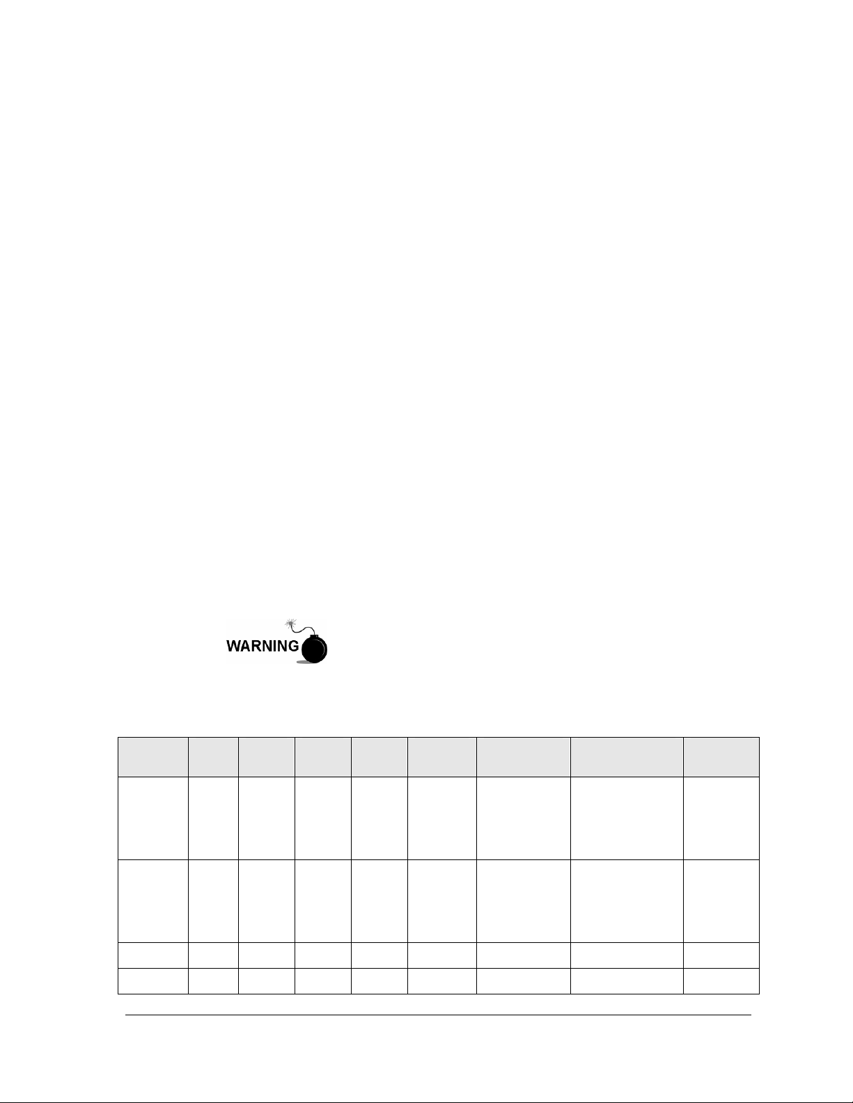
See Table 1—1 for the XFC family genealogy. This highlights the main differences
between the various devices.
XFC
Model
6200EX 1
6201EX 1
DIV
Class
Table 1—1 XFC Family Genealogy
Multi
Tube
Orifice
Meter
●
The XFC G4 6200/6201EX (G4 EX) is approved for installation in
Classified/Potential Hazardous Locations where an explosive
atmosphere may be present. Follow precautions and
requirements for installation, maintenance and service of
equipment according to Local and National Electrical Codes and
the “Warnings” contained in this manual.
Pulse
Meter
● External External External
Battery
Charger
External External External
Max. Battery
Capacity
Communication
Equipment
Max. TFIO
Modules
12-Point
I/O
Optional
Expansion
Card
12-point
I/O
Optional
Expansion
Card
6410 2 ● ●
6411 2 ●
On Board 26AH External N/A
● On Board 26AH External N/A
2104349-001 – rev. AB Page 1–1
Page 18
XFC
Model
6413 2 ● ●
6414 2 ●
6713 2 ● ●
6714 2 ●
DIV
Class
Multi
Tube
Orifice
Meter
1.1.1 Capabilities
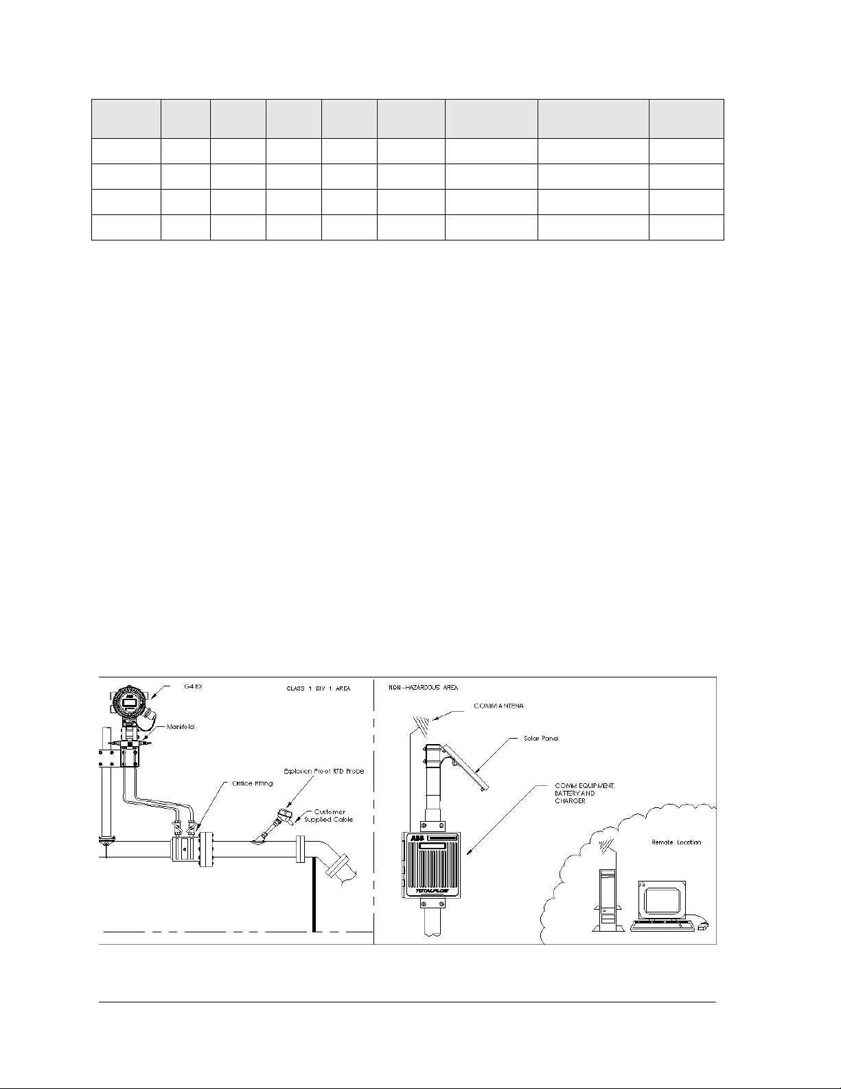
The G4 EX is packaged in a small, explosion-proof cast aluminum enclosure
which accommodates the processor board, termination board and display. The
power supply, charging source and radio communication applications must be
housed in separate accommodations. See Figure 1–1.
For the G4 EX, the integral multivariable transducer (EXIMV) is a separate unit
with no internal electronics and is attached to the bottom of the enclosure via a
threaded neck. This contains the wiring for the connection to the electronics that
are located in the enclosure.
The G4 EX defaults to the retention of daily and log period records for 40 days
and the retention of 200 events. These defaults can be extended, limited only by
the file storage spaces on the device.
The G4 EX may be used in conjunction with a laptop that is running PCCU32
software. PCCU32 is required for initial setup and setup of the advanced features.
Pulse
Meter
● On Board 26AH Internal 3
● On Board 42AH Internal 6
Battery
Charger
On Board 26AH Internal 3
On Board 42AH Internal 6
Max. Battery
Capacity
Communication
Equipment
Max. TFIO
Modules
The G4 EX maintains a history of alarms as well as average differential pressure
(DP), average static pressure (SP), average flowing temperature (Tf),
accumulated volume, energy and an average extension.
The G4 EX can be programmed to calculate flow rates and volumes in
accordance with either AGA-3, AGA-7 or ISO-5167.
Supercompressibility calculations can be performed in accordance with either NX19, AGA-8 or ISO 12213-2.
Figure 1–1 Typical G4 EX Installation
Page 1–2 2104349-001 – rev. AB
Page 19

1.1.2 Functionality
Functions of the G4 EX reflect a design that is practical, straightforward and
efficient. It is simple to use and easy to learn. This functionality allows for saving
time that is usually allotted for calculations and report preparation. This flow
computer allows the user to perform the following with a minimum of effort,
maximum speed and greater accuracy.
Complete log period flow and operational records that are reported hourly
(default), including:
• Average static pressure
• Average differential pressure
• Average flowing temperature
• Integral
• Corrected volume total
• Corrected energy total
• Operating status and alarms
• Flow time
Complete daily flow records, including:
• Average static pressure
• Average differential pressure
• Average flowing temperature
• Average extension
• Corrected volume total
• Corrected energy total
• Operating status and alarms
Complete daily operation statistics, including:
• Percent flowing time
• Percent back flow time
• Percent out of limits (programmable) on SP, DP, Tf and flow rate
• Minimum and maximum values for SP, DP, Tf and flow rate
1.1.3 Flow Computer Calculations
The records and statistics generated are based on the following calculation
methods of the G4 EX:
• Calculation of flow rates and volumes in accordance with AGA 3–85, AGA 3–
92, AGA-7 or ISO-5167.
• Calculation of flow rates and volumes in accordance with AGA-8 92 Gross or
Detail or NX-19 Supercompressibility Standards.
• Calculation of flow extension for the AGA3-92 equation is
per second.
• The flow extension reported for the log period is:
SpDp
*
Tf
67.459
+
*
SpDp
, once
67.459
+Tf
ondsintimeflow
sec*3600/
2104349-001 – rev. AB Page 1–3
Page 20

• Calculation of the flow extension for the AGA3-85 equation is SpDp * ,
once per second.
• Extrapolation of flow accumulation during transducer calibration or calibration
checks.
• Selection of all coefficients for calculation; the calculation of dynamic factors
(dependent upon DP, SP and Tf) using averages is based on one second
samples.
• Sample set of most recent calculations allowing subsequent verification.
• Monitoring of the operational limits, minimums and maximums to ensure
detection and reporting of malfunctions or abnormal site conditions.
• Acceptance and storage of system constants from the PCCU32 or remote
communications protocols.
• Storage of data records and operational events is determined by user (based
on available memory).
1.1.3.1 Additional Features
Additional features of the Totalflow system’s flexibility include the following:
• Programmable differential pressure zero cutoff.
• Programmable bi-level security codes to prevent unauthorized access to and
configuration of the G4 EX or user-configurable Role Based Security Access
(RBAC).
• Internal 100 Ohm platinum RTD resistance curve fit with user-programmable
single point offset or 3/5-point user-calibration of the RTD input.
• Quick, simple calibration procedures for transducer.
• Real-time clock providing a highly stable time base for the system.
• Proper battery and solar sizing is determined by geographic location of the
unit and total power consumption of the system. Totalflow project engineers
can select the appropriate battery and solar requirements for the user’s
specific application. Larger capacity batteries are available to increase
autonomy, if required.
• Three available power sources:
External solar panel (standard)
External AC or AC to DC power
External 24/12 VDC power
• Liquid crystal display (LCD) programmable to allow monitoring of the G4 EX
operations and can display any variable that has a register (for example,
displays current static pressure).
• Three serial communication ports are available on the G4 EX: 1 dedicated
RS-232 Local and 2 user-programmable RS-232/RS-485 Remote
Communication ports.
• USB and 10Base T Ethernet port.
• USB or RS-232 serial may be ordered as local, externally accessible Local
Communication Interface port.
1.1.4 Log Period Records
Each record has entries that contain the following information (and more):
• Average static pressure
• Average differential pressure
Page 1–4 2104349-001 – rev. AB
Page 21

• Average flow temperature
• Calculated volume
1.1.4.1 Log Period Data Entries
Log period data entries are made every 60 minutes, by default. The user may
change this period to any one of the seven (7) choices (1, 2, 5, 10, 20, 30, 60).
Choosing a log period of less than 60 minutes will result in additional records
being logged. As a result, this requires more storage space to hold a full day’s
data. The log period must never be less than the volume calculation period.
1.1.4.2 Volume Calculation Period Entries
Volume calculation period entries are made every second, by default. The user
may change this period up to 60 minutes. API 21.1 strongly suggests a volume
calculation period (QCP) of once per second.
The volume calculation period should never be greater than the log period and
should be evenly divisible into the log period.
Volume calculations are completed, following the top of the current period (i.e., top
of the hour, top of the minute, each second).
1.1.5 Display Function
During operation, the front panel LCD continuously scrolls through the operating
parameters. Table 1—2 shows the typical displayed parameters; however, many
parameters with a register address can be displayed. The duration that the
parameter is displayed can vary from 1 to 255 seconds (default is five seconds); a
setting of zero seconds will set any item to Off. See the Program Display section
and the PCCU32 help files for additional information.
Table 1—2 Typical G4 EX Display Options
Display Description
DATE/TIME MM/DD/YY HH:MM:SS Current date and time, 24 hour clock
YEST DP LOW NN PERCENT Yesterday’s % time below DP Low Set Point
YEST DP HIGH NN PERCENT Yesterday’s % time below DP High Set Point
FLOW RATE NNNNNN.N SCF/HR Current flow rate, programmable SCF, MCF or MMCF
TOTAL ACCUM VOL NNNNNN.NN MCF
DIFF PRESS NNN.N IN. H2O Differential pressure, inches H2O
PRESSURE NNN.N PSIA Static pressure absolute, PSIA
FLOW TEMP NN.N DEG. F Flowing temperature, °F
YEST VOL NNNN.N MCF Yesterday’s volume, programmable SCF, MCF or MMCF
PERIOD VOL NNNN.N SCF Last volume calculation period volume
BATTERY VOLTAGE NN.N VOLTS Battery voltage as supplied by external unit
M_FLOWRATE NNNNNN.N SCF/HR Minute average flow rate
STATION ID ID of unit
ORIFICE DIAMETER N.NNNN INCHES Size of orifice plate
Total accumulated volume., programmable SCF, MCF or
MMCF
2104349-001 – rev. AB Page 1–5
Page 22
1.1.6 Display Annunciators
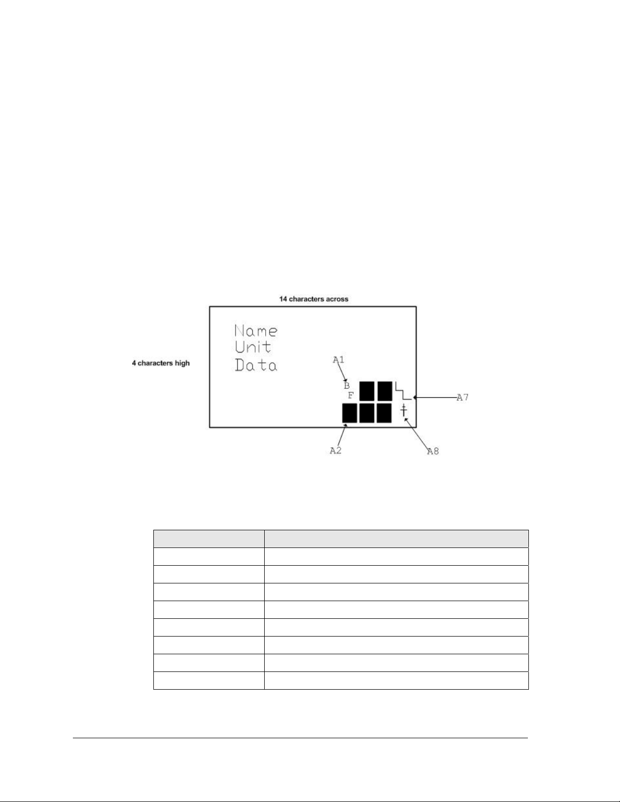
Since a primary function of the G4 EX is to provide complete volume and
operational records, it is important to indicate unusual or alarm conditions as they
occur. This is supported on the LCD in the Annunciator display area shown in
Figure 1–2.
In the G4 EX computer, the status and alarm indicators are user programmable.
Table 1—3 identifies the default annunciator locations. Please consult the
PCCU32 help files for additional instructions on programming the annunciators.
Whenever an alarm is indicated, the G4 EX records it in the appropriate log period
flow record. These are automatically retrieved when data is collected. Visual
alarms and status codes are described in
Table 1—4.
Figure 1–2 Liquid Crystal Display (LCD) and Indicators
Table 1—3 Default Annunciator Locations
Annunciator Application
A1 Measurement Tube 1
A2 CIM 0
A3 Valve Control
A4 COM2
A5 Plunger
A6 Local-COM0
A7 System
A8 TF Remote – COM1
Page 1–6 2104349-001 – rev. AB
Page 23
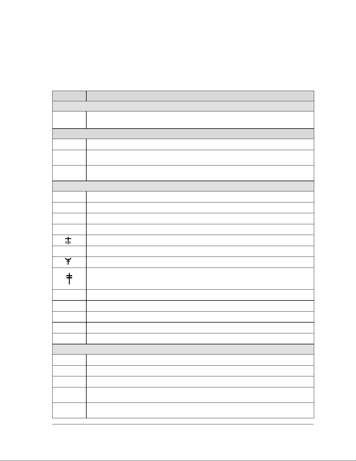
Table 1—4 G4 EX Status and Alarm Description
Indicator Description
System
L
L
1
↑
↓
Low Lithium Battery Alarm: When LL (low lithium) is displayed, lithium battery voltage is not
sufficient to maintain SRAM data. A new lithium battery measures approximately 3.6 VDC.
Display Application
A number represents the Display Group number currently being displayed.
The displayed item’s value is above the Data High Limit value specified on the display Item
Setup screen.
The displayed item’s value is below the Data Low Limit value specified on the display Item
Setup screen.
Communications
→
←
!
+
?
M
m
L
n
u
BF
Transmitting Data: Sending a response.
Receiving Data: Processing request.
Negative Acknowledgement (Nak) w/packet list.
Positive Acknowledge (Ack) of receipt of request.
Waiting for Positive Acknowledgement: Waiting for response after transmission.
Exception Alarm Processing.
ID Recognized: Recognized and receiving request.
Listen Cycle: Flashes if this remote port is active and running Totalflow Remote Protocol.
Flashes in sync with listening cycle that occurs at 1, 2 or 4 second intervals. May not be visible
if baud rate is faster than 2400. Annunciator will remain on if listen cycle is set to zero.
MODBUS ASCII: MODBUS ASCII protocol selected for the port assigned to this annunciator.
MODBUS RTU: MODBUS RTU protocol is selected for the port assigned to this annunciator.
Local Protocol: Displayed when PCCU32 port is active and running Totalflow Local Protocol.
Network (Ethernet).
USB.
Measurement Application
Back Flow Condition: Visible only when DP variable displayed.
Z
H
A
AD
Zero Flow Condition: Visible only when Flow Rate displayed.
Hold: Displayed when PCCU32 has entered Calibration mode on a Measurement Application.
Alarm Condition: Need to view alarm. The user may need to compare application limits to
current values to determine where the alarm condition is present.
A to D Failure: Displayed if A to D Converter’s differential pressure, absolute static pressure or
temperature readings exceed maximum counts or are less than minimum counts.
2104349-001 – rev. AB Page 1–7
Page 24

1.2 G4 EX Computer Hardware
The G4 EX computers are housed in an explosion-proof enclosure. The
components that comprise this are as follows:
• G4 EX Enclosure (3R/IP53 with breather drain installed; 4X/IP66 without
breather installed)
• G4 EX Main Processor Board
• G4 EX Termination Board
• Lithium Battery
• Engine Card
• G4 EX Liquid Crystal Display (LCD) Assembly
• PCCU Connector
Internal Connector
Explosion Proof External Connector – USB/Miltary (optional)
• Explosion Proof Integral Multivariable Transducer with Raw Sensor Board
Interface
• Resistive Temperature Detector
Standard RTD (DIV 2)
Explosion Proof RTD (DIV 1)
1.2.1 G4 EX Enclosure
The custom-designed, explosion-proof enclosure consists of a cylinder shaped,
cast aluminum housing, powder coated, with front and rear end caps for access to
internal components (see Figure 1–3 through Figure 1–5). This enclosure may be
direct mounted, pipe mounted on the meter run using a pipe saddle or mounted on
a stand alone pipe.
The enclosure features three (3) exterior hubs for wiring:
• Communication and power
• Resistive temperature detector (RTD)
• Input/output wires
The end caps have precision engineered threading and are susceptible to damage
if treated roughly. End caps are water tight, corrosion resistant and NEMA 4X
rated. Unauthorized removal of the end caps are protected with a 1/16”
countersunk hex head set screw on each end cap.
Remove power from the device, or insure the area is known to
be non-hazardous before removing any enclosure cover. For
further information, refer to the certification drawing indicated on
the device’s nametag and national and local electrical codes.
Do not attempt to loosen the end cap before loosening the set
screw. Doing so may damage threads on the unit.
1.2.1.1 Dimensions
Width
Unit
US 7.87” 9.50” 11.25” 8.34”
w/o External
PCCU
w/ External
PCCU
Height Depth
Page 1–8 2104349-001 – rev. AB
Page 25
Width
Metric 199.90 mm 241.30 mm 285.75 mm 211.84 mm
1.2.1.2 Installation and Weight
Unit Weight
W/ EX PCCU
Connector
Pipe Mounted
Depth
Direct Mounted
Depth
US 15.65 lbs. 16.35 lbs. 9.69” 8.34”
Metric 5.84 kg 6.10 kg 246.13 mm 211.84 mm
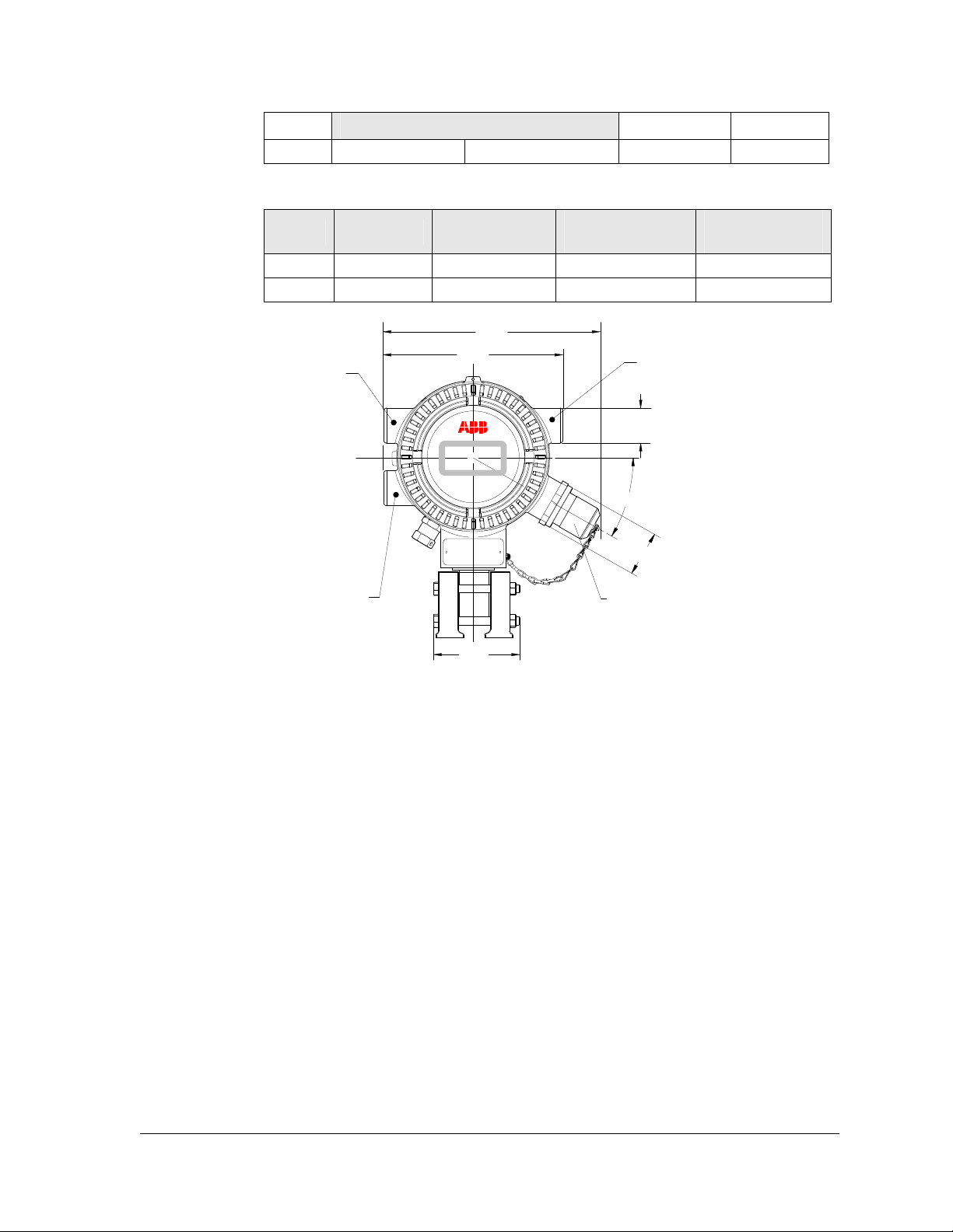
(9.50)
¾ NPT CONDUIT ENTRIES
¾ NPT CONDUIT ENTRIES
XFC
(7.87)
(3.76)
G4
EX
¾ NPT CONDUIT ENTRIES
(01.53)
(30º)
(01.84)
OPTIONAL EXTERNAL
PCCU FLAMEPROOF
HOUSING (2101416-001)
Figure 1–3 G4 EX Enclosure
2104349-001 – rev. AB Page 1–9
Page 26
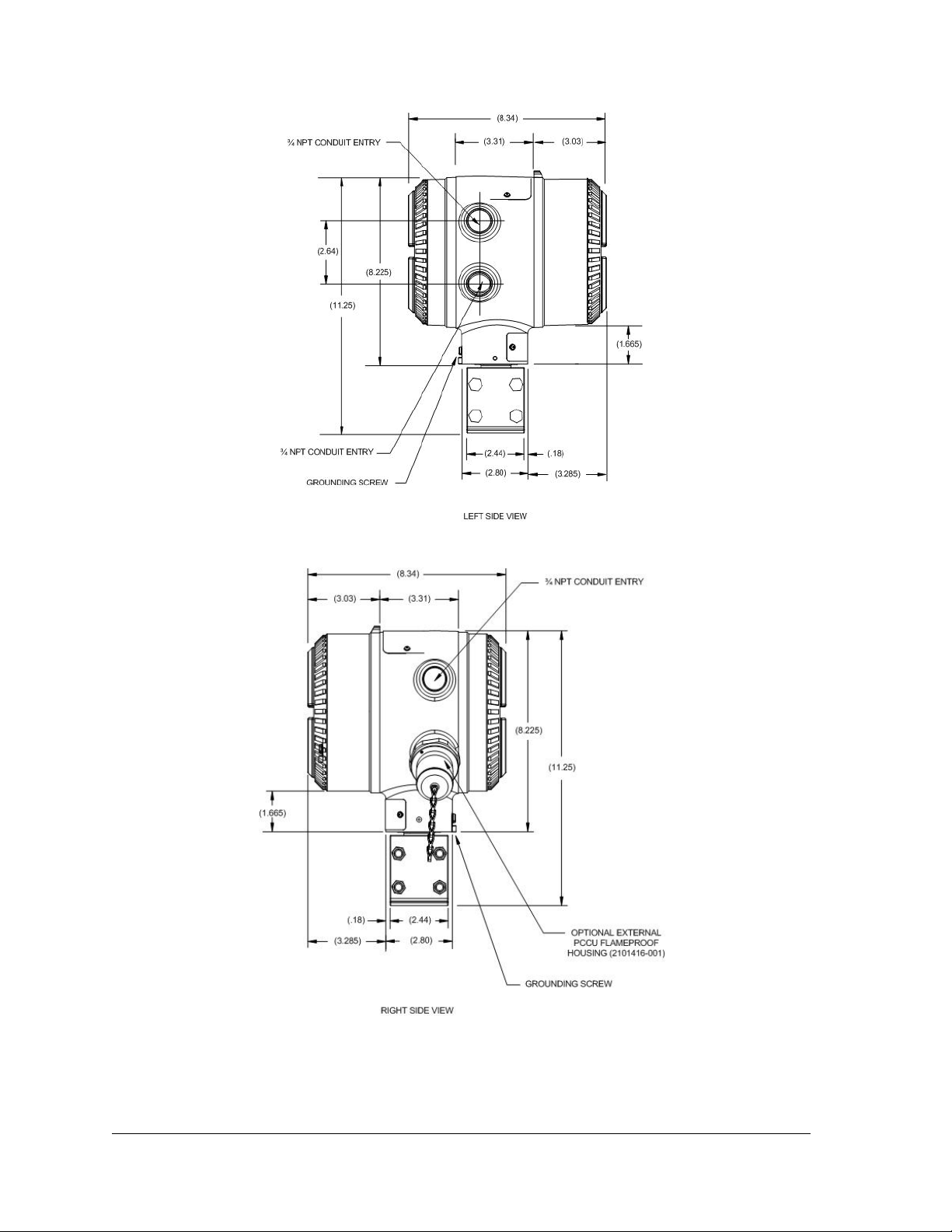
Figure 1–4 G4 EX Enclosure Left Side
Figure 1–5 G4 EX Enclosure Right Side
Page 1–10 2104349-001 – rev. AB
Page 27
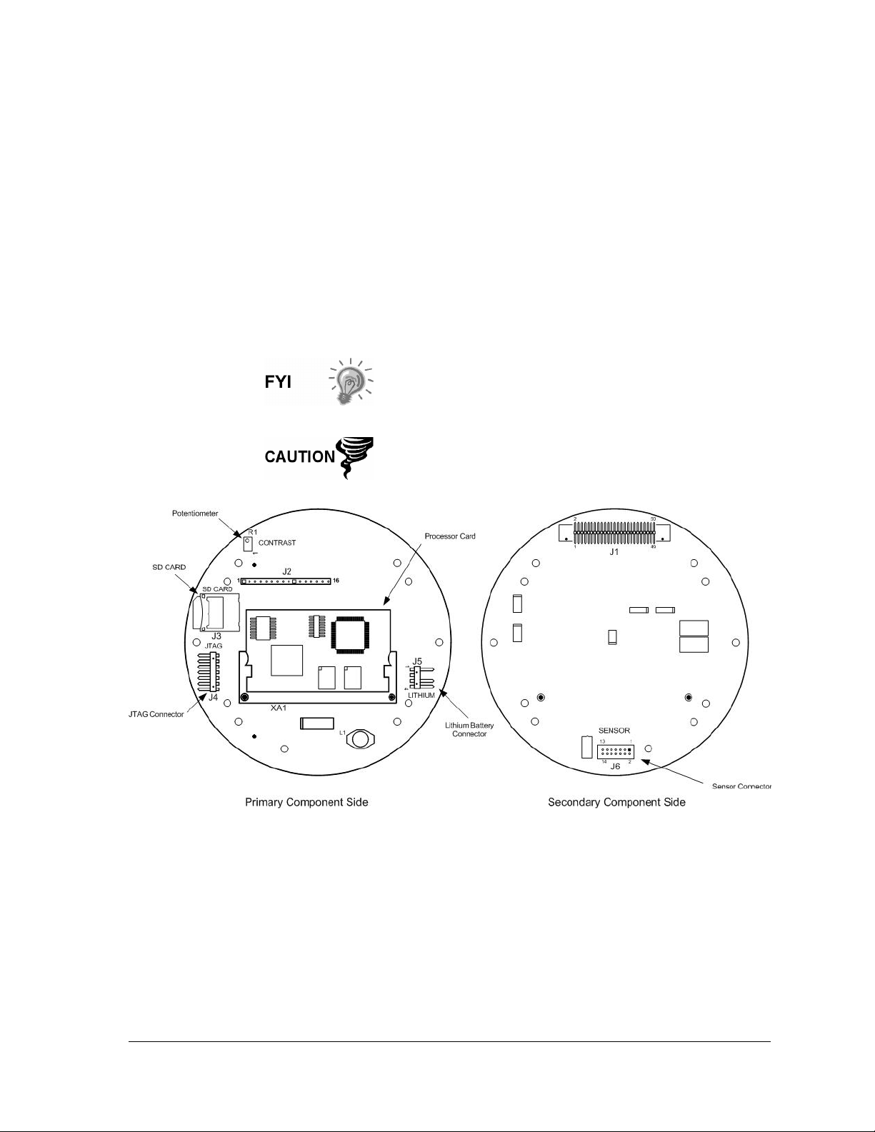
1.2.2 G4 EX Main Processor Board
The G4 EX main processor board is mounted inside the front end cap, directly
behind the display assembly (see Figure 1–6 ).
User applicable connections on this board consist of the following:
• uSD Card (J3)
• Contrast Display Potentiometer (R1)
• LCD Display Connector (J2)
• Lithium Battery Connector (J5)
• Engine Card Connector (XA1)
• Sensor Interface Connector (J6)
• Termination Board Connector (J1)
The G4 EX transducer assembly utilizes a small electronic
board that contains the factory characterization data. This
allows the main electronics on the sensor assembly to be
individually field replaceable in the event of failures.
Installation and/or maintenance of electric components
must follow guidelines stipulated in the certification
drawings shipped with this unit and adhere to local codes.
Figure 1–6 G4 EX Main Processor Board
1.2.2.1 Engine Card
An engine card plugs into the G4 EX board. All processor and memory
components reside on this engine card. The engine card uses a low power
processor running at 203 MHz with 16MB PSRAM for program execution and data
storage, 32MB Flash for application storage and 256 bytes of serial E
2
PROM. A
lithium backup battery is located on the main G4 EX board. Application programs
and configuration files are stored in non-volatile Flash.
2104349-001 – rev. AB Page 1–11
Page 28

1.2.2.2 G4 EX Main Processor Board Specifications
The G4 EX Main Processor board is designed as a general purpose motherboard
for the 6200/6201EX devices.
Table 1—5 G4 EX Main Processor Board Specifications
Component Description
Power
External Power
Charger
9 to 30 VDC
SWVBAT: 1 fused with 2.5 amp PTC
VBAT: 1 fused with 2.5 amp PTC
No Charger
• Application (Totalflow.exe) runs out of 16M SRAM. RAM memory has
lithium backup battery.
Memory
• Application and configuration files permanently stored in 32M Flash.
• Registry (MAC address, etc.) is stored in 256 byte E
• SD Card optional (512M/1G)
• 6 Ports Available
• Dedicated PCCU/MMI (RS-232 or USB)
• 2 Onboard User Programmable RS-232/RS-422/RS-485 Ports
Comm. Ports
• USB (Client)
NOTE: A special cable is required, and the user must check with Totalflow for a list of
drivers to support Client peripherals.
• Ethernet Bluetooth – Standard on the Main Electronics Board
Analog Inputs
Digital Inputs
Digital Outputs
I/O Module Interface
LCD Interface
Security Switch
I/O Scan Rate
Time Base Stability
Pulse Input
Bandwidth
1 (0-10 VDC)
1 (State Change or Pulse to 20 kHz) operating at a 50% duty cycle
with (Selectable De-bounce enabled 100 Hz)
1 FETs, sink = 2.5 Amp Max.Open Drain PTC, with 1500 W Transient
protection
Optional plug-in I/O daughter card with 12 I/O (3 AI, 1 AO, 4 DI and 4 DO)
Dedicated interface for Liquid Crystal Display (LCD)
On/Off Bi-level on-board Security (See Chapter 3 for details)
1 time per second
± 7.5 ppm (parts per million)
Up to 20 KHz (Linear flow meter only)
2
PROMSD Card
1.2.3 G4 EX Termination Board
The G4 EX Termination board can be accessed by removing the rear end cap
(see Figure 1–7). All user connections should be routed through the cable entry
hubs and should adhere to local codes.
Located on the Termination board, the user will find connectors for two (2)
communication ports: RS-232, RS-422 or RS-485 (software selectable). The user
should also note that there is a dedicated port for RS-232 local communications.
This is a plug type port and will connect to an internal PCCU connector or an
Explosion Proof External PCCU connector.
Page 1–12 2104349-001 – rev. AB
Page 29
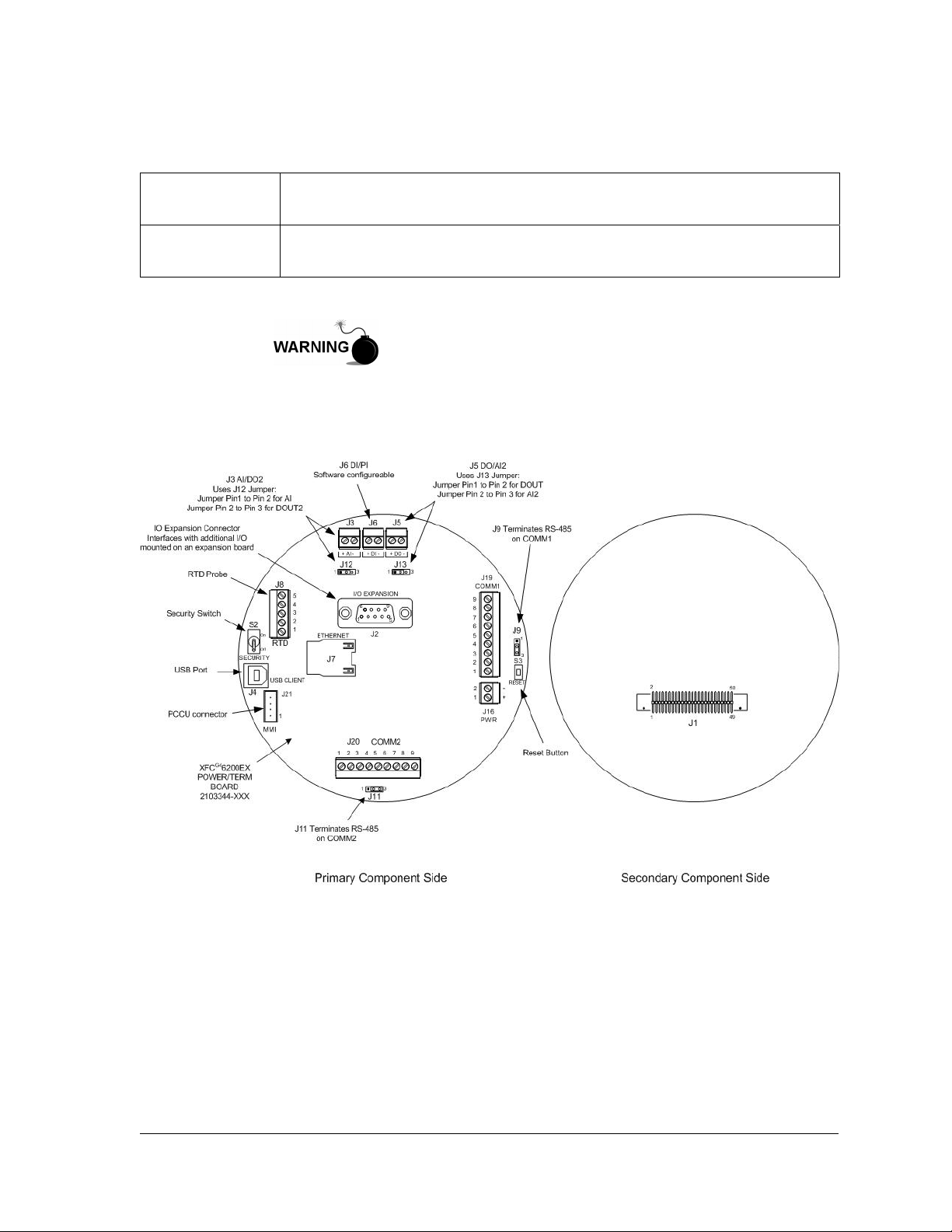
For more information on the Explosion Proof PCCU connector, see the
corresponding section. Additionally, for the internal PCCU connector, see the
section under Optional Equipment in this chapter.
COM 1 Port
Com 2 Port
Remote communication wiring for Port 1 is handled using the J19 connector
and the SW1 communication switch.
Remote communication wiring for Port 2 is handled using the J20 connector
and the SW2 communication switch.
The XFC G4 6200/6201EX (G4 EX) is approved for installation
in Classified/Potential Hazardous Locations where an explosive
atmosphere may be present. Follow precautions and
requirements for installation of equipment according to the
certification drawing indicated on the device’s nametag and
National and Local Electrical Codes.
Figure 1–7 G4 EX Termination Board
1.2.3.1 On-Board I/O
The G4 EX Termination board provides similar base I/O as earlier XSeries models
but with a reduced number due to enclosure restrictions. This includes:
• 1 User AI
• 1 User DO
• 1 User DI
• Interface for I/O daughter card: 3 AI, 1 AO, 4 DI (NAMUR rated) and 4 DO
2104349-001 – rev. AB Page 1–13
Page 30
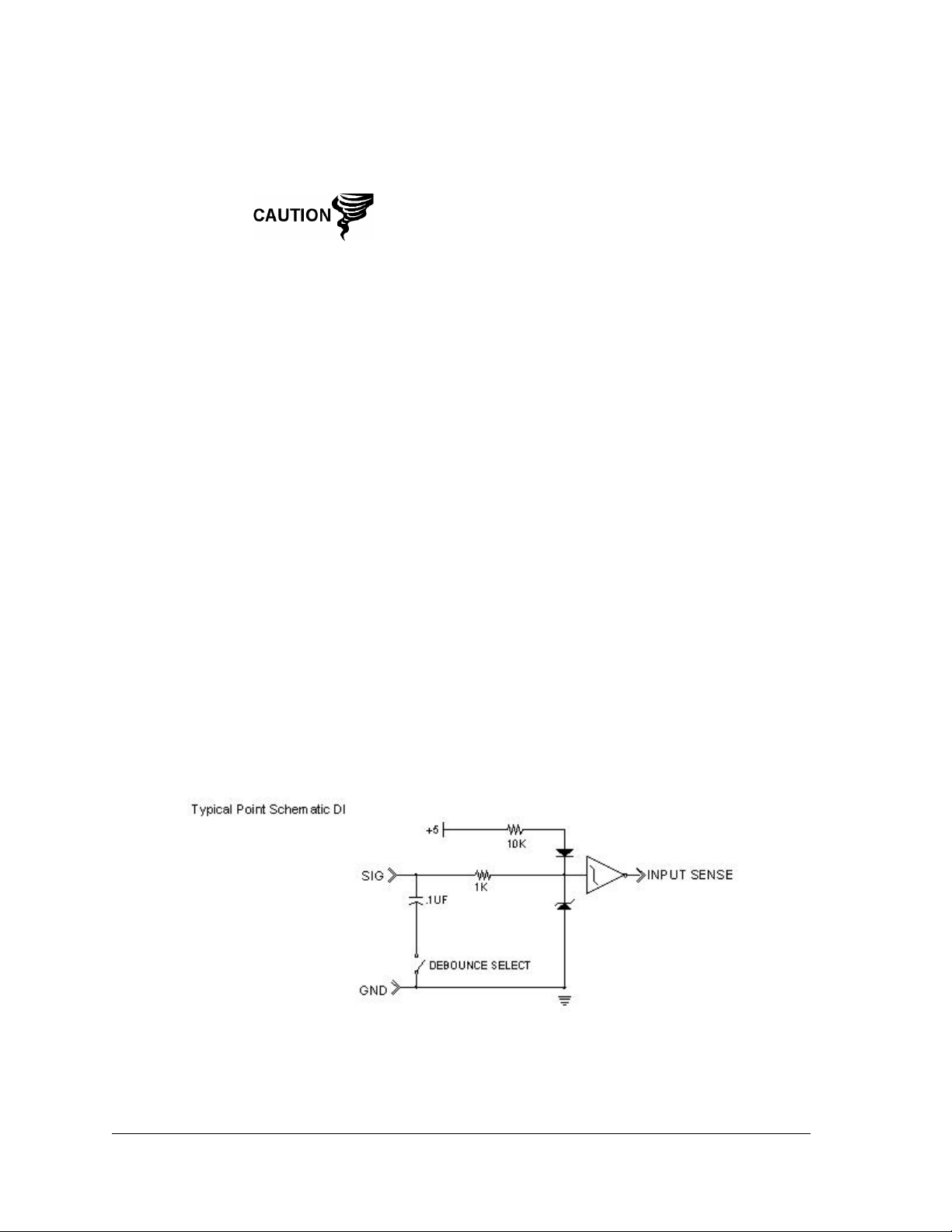
1.2.3.2 Digital Input
The G4 EX provides one digital/pulse input as a means to monitor external
equipment.
When connecting or disconnecting any wires to the G4 EX
boards, the user should remove all power sources and
insure that they are grounded properly.
The digital input reads an external contact. This is primarily used as a status input
to read external equipment. The contact must be closed to be considered “ON”.
The “ON” condition is recorded in the log period alarms and can trigger the action
of the G4 EX’s digital voltage output. OFF is defined as an open contact.
Selectable de-bounce can be enabled or disabled within PCCU32. See the
PCCU32 help files for additional information.
DI Electrical Specifications
• Open Circuit Voltage: 5 VDC (Internally pulled up to 5 VDC Nom.).
• Short Circuit Leakage Current: -395 uA typical.
• Input Capacitance: 0.1 ufd typical.
• Maximum Allowable Voltage Range on Input: -0.5 VDC to 15 VDC.
• Maximum Frequency Input: 100 Hz @ 50% duty cycle with de-bounce
enabled. 20 kHz @ 50% duty cycle with de-bounce disabled.
Input Specifications
• Dry Contact (form A), Open Collector or Active Voltage.
• Minimum contact resistance to activate input 1000Ω.
• Voltage threshold to deactivate the input: 3.1V (referenced to GND terminal).
• Voltage threshold to activate the input: 0.5V (referenced to GND terminal).
• Conductor pairs must be shielded to prevent spurious signals.
Typical DI Point Schematic
Figure 1–8 Typical DI Point Schematic
Page 1–14 2104349-001 – rev. AB
Page 31
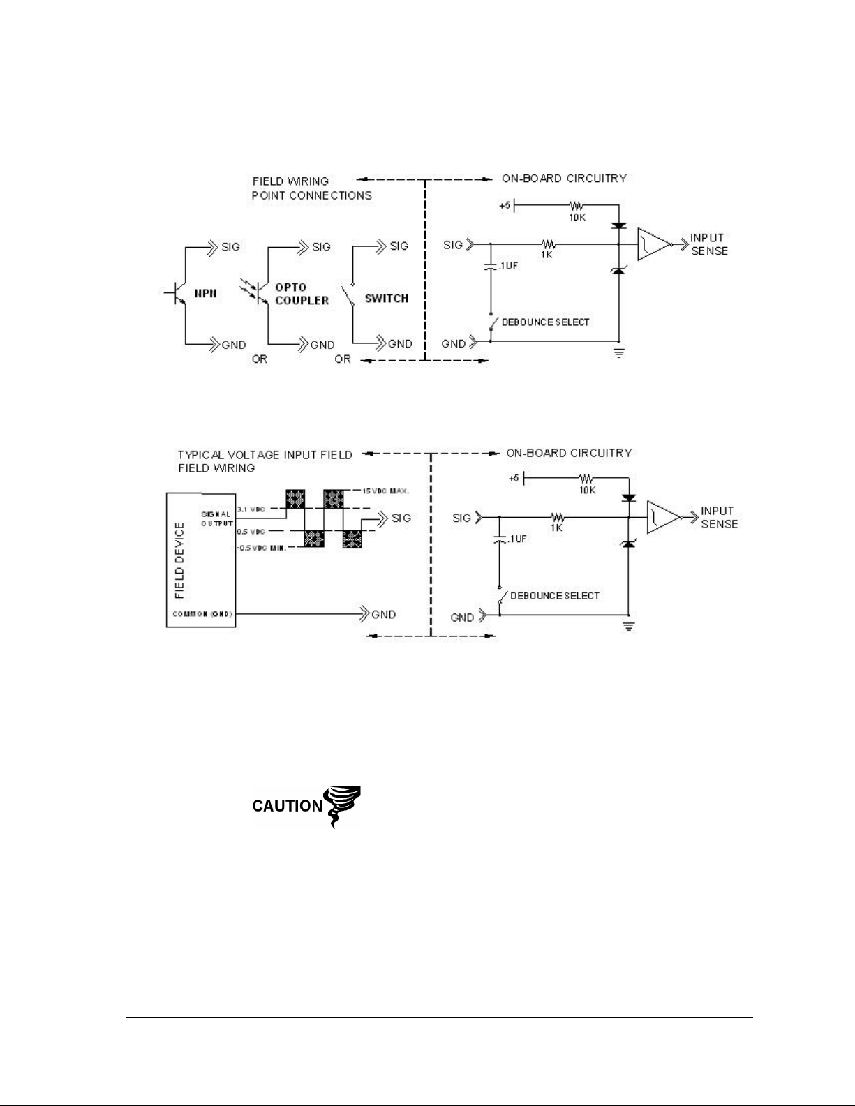
DI Connection Examples
Figure 1–9 DI Connection Example
1.2.3.3 Digital Output
The G4 EX provides one digital output (12 VDC or 24 VDC max.) as a means to
control external equipment.
When connecting or disconnecting any wires to the G4 EX
boards, the user should remove all power sources and
ensure that they are grounded properly.
The digital output can be used in conjunction with a measurement tube (AGA-3,
AGA-7 or liquid measurement) and triggered on the following measurement
parameters or conditions:
• Differential pressure over high limit
• Volume set point
• Differential pressure under low limit
• Flow temperature low
• Static pressure over high limit
2104349-001 – rev. AB Page 1–15
Page 32
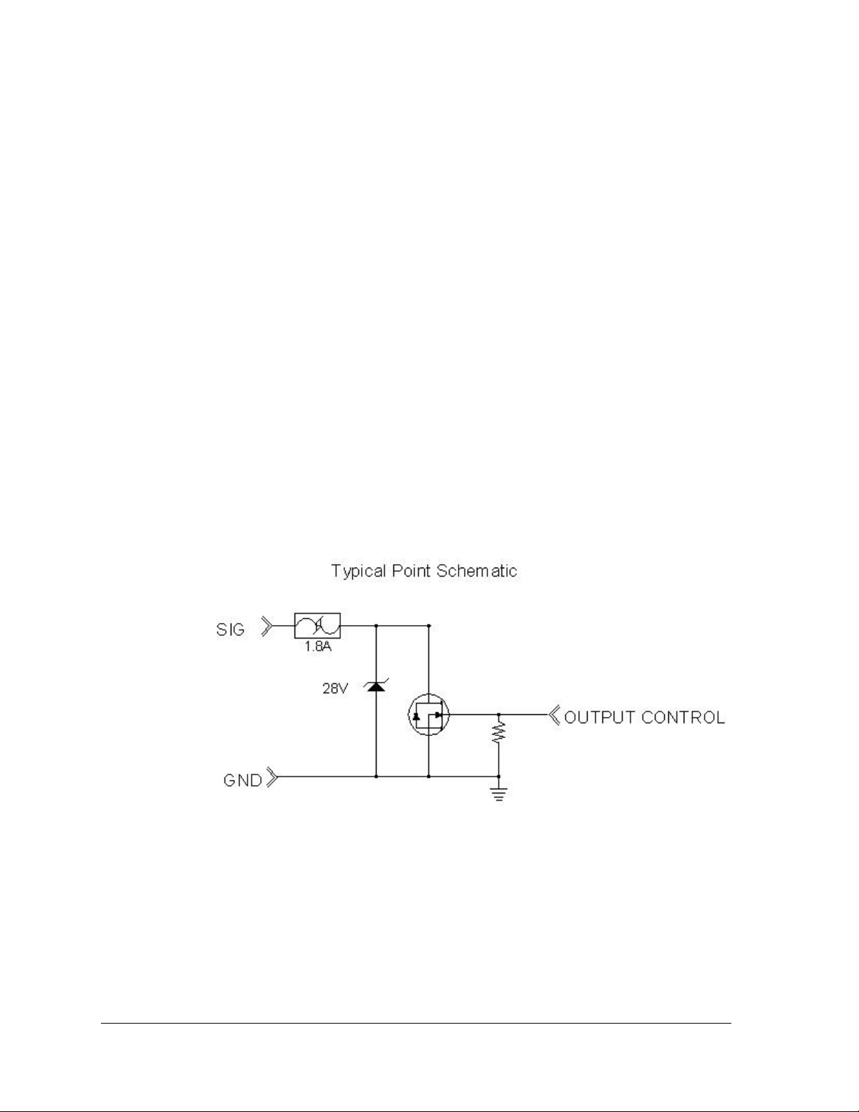
• Flow temperature high
• Static pressure under low limit
• Flow rate low
• Low charger voltage
• Flow rate high
• Remote sense is on
• Trip on digital input
• Custom programmable by Totalflow or user programmable with IEC 1131
programming language
DO Electrical Specifications
• Open circuit voltage: 0 VDC
• Short circuit leakage current: 0 uA typical
• Output capacitance: 1000 pF typical
• Maximum allowable voltage range on output: 0.5 VDC to 29.4 VDC
Output Specifications
• Open drain FET type
• “ON” resistance (Including PTC fuse resistance): 0.1Ω Typical
• Maximum pulse current: 3A for 5 seconds
• Maximum continuous sink current: 1.2A at 60
*
C or .75 at 85*C
Typical DO Point Schematics
Figure 1–10 Typical DO Point Schematics
Page 1–16 2104349-001 – rev. AB
Page 33
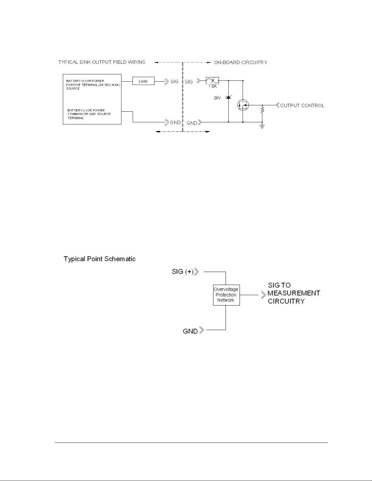
DO Connection Example
Figure 1–11 DO Connection Example
1.2.3.4 Analog Input
The G4 EX provides one analog input as a means of receiving data, represented
by continuously varying voltage/current.
• Open circuit voltage: 0 VDC
• Short circuit leakage current: 0 uA typical
• Input impedance: 103.5KΩ typical (0 to 10V)
• Measurable input voltage range: 0 to 10.34 VDC
• Maximum voltage on input: 30 VDC
Typical AI Point Schematic
Figure 1–12 Typical AI Point Schematic
2104349-001 – rev. AB Page 1–17
Page 34
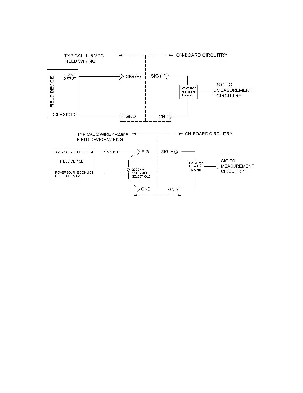
AI Example Connections
Figure 1–13 AI Example Connections
1.2.4 Explosion Proof Multivariable Transducer (EXIMV)
The EXIMV is an explosion proof version of the factory calibrated “Smart” Integral
Multivariable Transducer. The EXIMV is characterized over temperature so that
any changes occurring in the EXIMV or in the electronics can be compensated.
Providing the primary measurement capability for the G4 EX (see Figure 1–14 ),
the circuitry and characterization information are stored in the raw sensor board.
EXIMV specifications are discussed in Table 1—6.
The unit is designed to provide EMI/RFI protection of the low level signals and to
protect the circuitry from other environmental effects.
Page 1–18 2104349-001 – rev. AB
Page 35
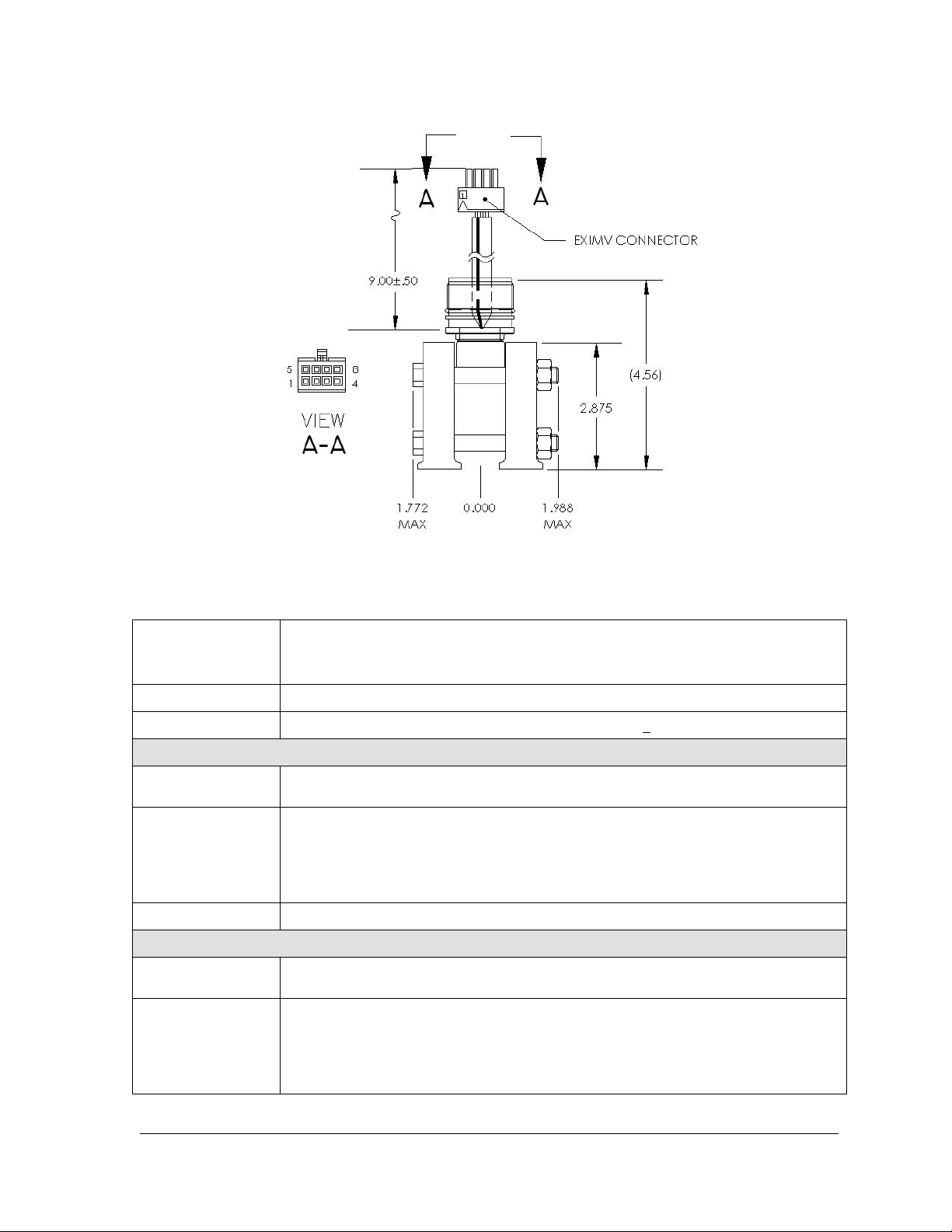
Figure 1–14 Explosion Proof Multivariable Transducer (EXIMV)
Temperature Limits
Resolution
Mounting Spec.
Accuracy
Ambient
Temperature Effect
Within the
Operational
Temperature Limit
Stability
Accuracy
Ambient
Temperature Effect
Within the
Operational
Temperature Limit
Table 1—6 Explosion Proof EXIMV Specifications
Compensated: -20°F to 140°F (-29°C to 60°C)
Operational: -40°F to 140°F (-40°C to 60°C)
Storage: -40°F to 185°F (-40°C to 85°C)
24 Bit A/D conversion (0.000012% FS) (0.0012% FS effective signal resolution)
Change from perpendicular (front to back around X-axis) <
Static Pressure
Linearity, Hysteresis and repeatability combined: ± 0.075% of user-calibrated spans from
20% to 100% of URL
± 0.075% of URL +0.06% of Reading
± 0.1% of URL (for 12 months)
Differential Pressure
Linearity, Hysteresis and repeatability combined: ± 0.075% of user-calibrated spans from
20% to 100% of URL.
± 0.075% of URL + 0.06% of Reading
0.5% URL
2104349-001 – rev. AB Page 1–19
Page 36
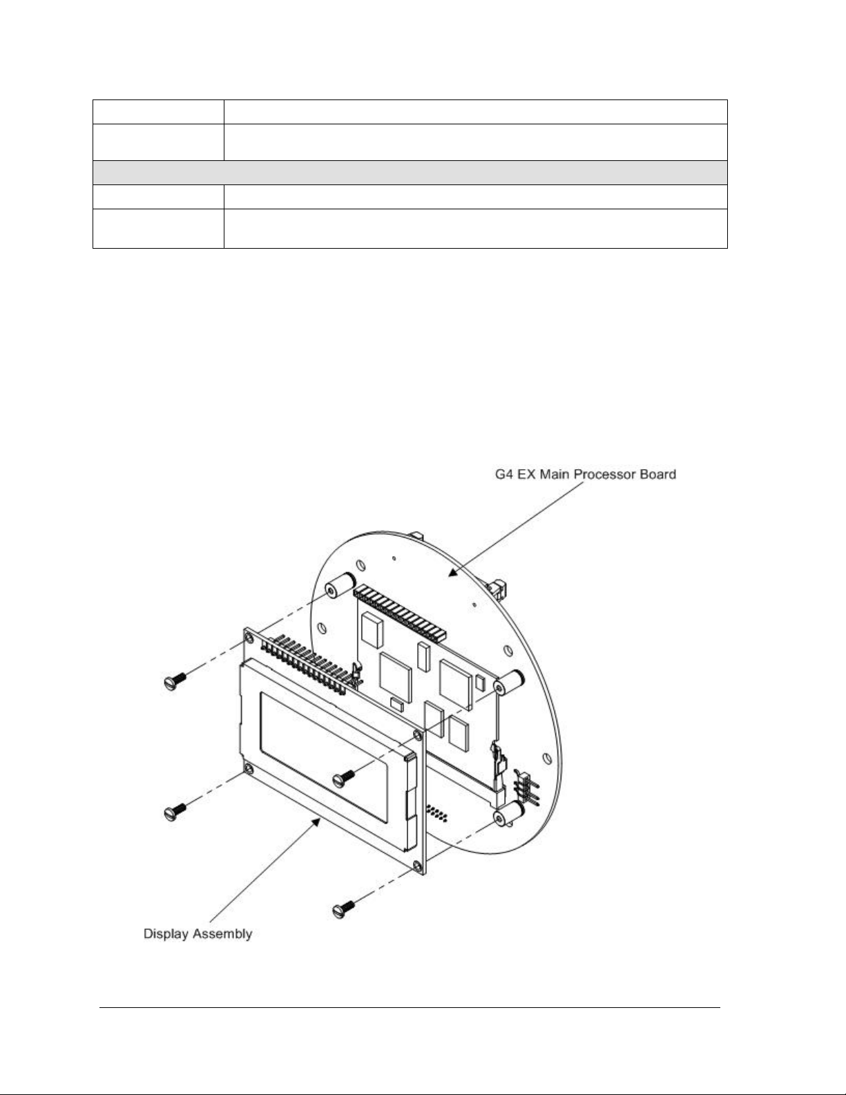
Stability
SP Effect
Operating Range
Accuracy
1.2.5 Display Assembly
± 0.1% of URL (for 12 months)
DP Zero per 1500 psi: ± 0.03% of URL (3200 psi maximum)
DP Span per 1500 psi: ± 0.1% of Reading (3200 psi maximum)
Temperature
-80°F to 750°F (-62°C to 339°C)
± 0.35°F (± 0.2°C)over Operating Range (as shipped from factory)
± 0.2°F (± 0.12°C) repeatability over Operating Range (after single point field calibration)
The G4 EX display assembly (see Figure 1–15) has a dedicated interface to the
Main Processor board from the 4x16 Liquid Crystal Display (LCD) via a 14-pin
connector.
The display utilizes four lines by 16 characters. The user can then customize the
annunciators based on their own specific needs. The alarm codes and
annunciators communicate a basic message(s) to the user and indicate a need for
further attention. These codes are location dependent and may mean different
things, based upon which character space the code appears in. These are also
user configurable.
Figure 1–15 Liquid Crystal Display (LCD) Assembly
Page 1–20 2104349-001 – rev. AB
Page 37
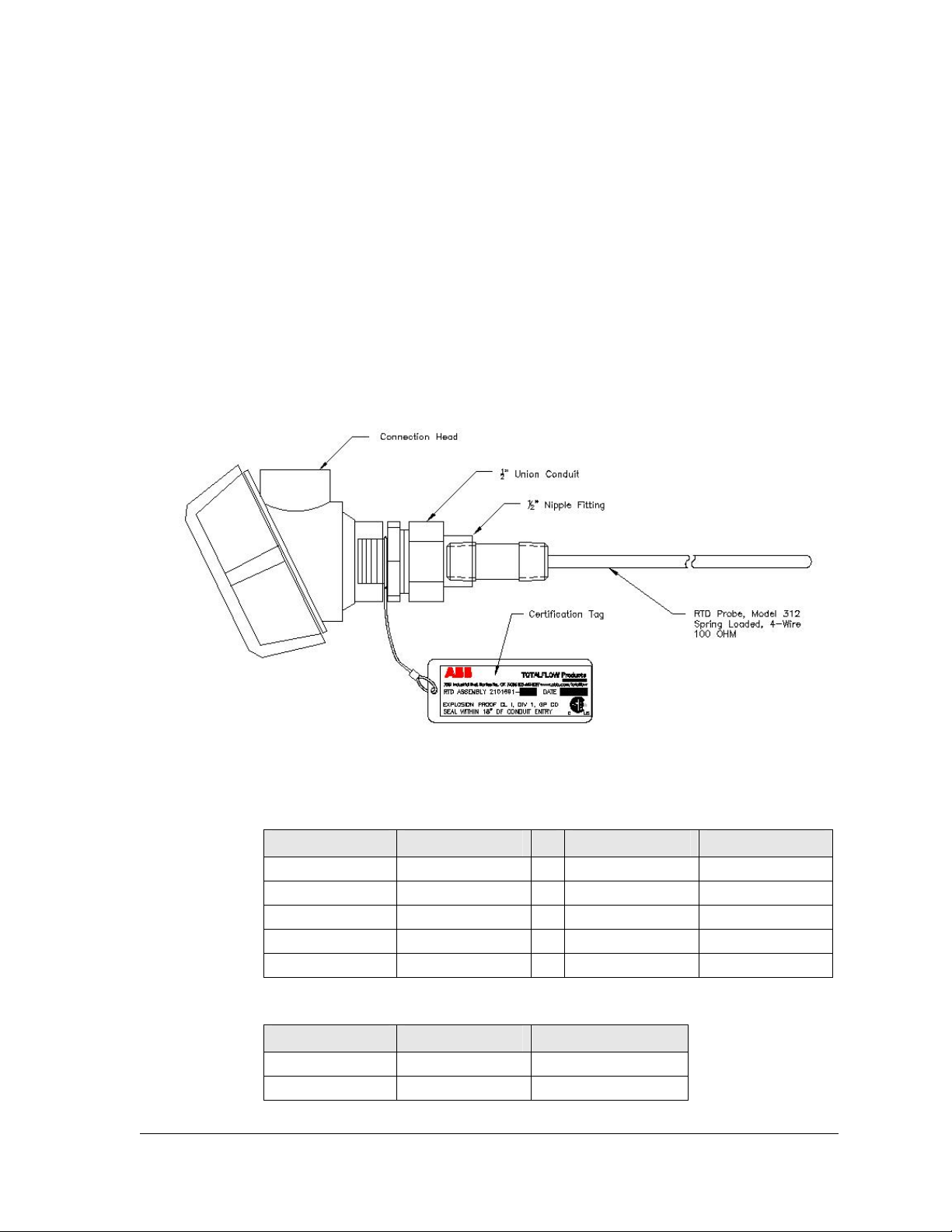
1.2.6 Resistive Temperature Detector (RTD)
Totalflow offers a choice of two RTD options. The 100 OHM Platinum RTD
measures real-time flowing temperature of the gas.
1.2.6.1 Standard RTD
The standard RTD is not DIV 1 approved; therefore, this RTD may only be
installed and used in general purpose areas.
1.2.6.2 Explosion Proof RTD
The Explosion Proof RTD is available for use in DIV 1 areas (see Figure 1–16).
Two probe lengths are available: 10” and 16”. See Table 1—7 for standard
probes, based on Thermowell “U” lengths and Table 1—8 for standard
Thermowells that are based on thread diameter.
Figure 1–16 Explosion Proof Resistive Temperature Detector
Table 1—7 Standard RTD Probes
“U” Length Part Number
2.00” 2101691–020 6.00” 2101691–060
2.50” 2101691–025 7.00” 2101691–070
3.00” 2101691–030 8.00” 2101691–080
4.00” 2101691–040 9.00” 2101691–090
5.00” 2101691–050 10.00” 2101691–095
“U” Length Part Number
Table 1—8 Standard Thermowells
Thread Diameter “U” Length Base Part Number
½” 2” through 10” 1622305
1” 2” through 10” 1622302
2104349-001 – rev. AB Page 1–21
Page 38
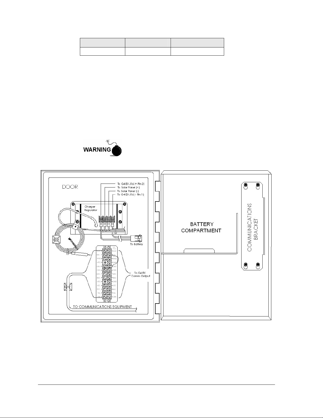
Thread Diameter “U” Length Base Part Number
3/4” 2” through 10” 1622300
1.2.7 6270 Optional Equipment Unit (OEU)
The G4 EX unit is designed to be located in DIV 1 Hazardous areas; therefore,
many features and requirements of the unit are housed in a separate enclosure
that is located in DIV 2 or General Purpose areas.
Space is provided inside the enclosure to house a variety of remote
communication devices: transceiver, cellular phone, battery, changing source and
additional I/O (see Figure 1–17).
The battery compartment shelf houses various optional battery packs that are
available for the OEU, from eight (8) ampere hours up to 26 ampere hours.
Installation of the battery is discussed later in the manual.
The 6270 OEU system with battery and solar panel is rated
for Class I, Division 2 locations only or can be installed in
non-hazardous locations.
Figure 1–17 Optional Communication Enclosure
1.2.8 Solar Panel
A solar panel can be configured in the system to provide a charging source for the
battery. DIV 1 installations would require that the solar panel and battery pack be
Page 1–22 2104349-001 – rev. AB
Page 39
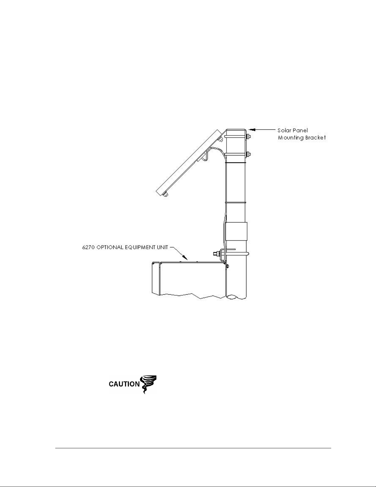
installed in a General Purpose or DIV 2 area. Typically, the solar panel would be
connected through a charger regulator that is located in the 6270 OEU.
Depending upon power/charging requirements, the unit may be configured for a 5watt, 10-watt, 20-watt or 30-watt solar panel. The panel is designed to be mounted
on a 2-inch extension pipe.
Figure 1–18 Solar Panel – Typical Installation
1.2.9 Lithium Battery
The following information displays the technical information regarding the lithium
battery housed within the G4 EX.
When the G4 EX is in storage, it is recommended that the
lithium battery be disabled (unplugged from J5 connector) to
prevent power drainage. Not doing so can cause the battery
to lose power within six months.
2104349-001 – rev. AB Page 1–23
Page 40

Nominal Capacity
@ 2 mA, to 2V
Technical Data
2.1 Ah
Rated Voltage
Wires
Enclosure
Mounting
Operating
Temperature Range
3.6 V
AWG 24
UL 94V2
Hook and Loop Fastner
-55°C to +85°C/-67°F to +185°F
1.3 G4 EX Application Licensing
The G4 (fourth generation) EX offers the user unrivaled power and flexibility. The
G4 EX units can support far more applications than the G3 (third generation)
devices. Various applications require that Totalflow pay a royalty to third party
vendors. As such, Totalflow has developed a credit system for handling
application loads beyond what would be required for a typical G3 meter run.
Application credits are required to enable many of the applications.
From the factory, the G4 EX has four general credits installed. Several system
configurations are possible with these four general credits:
• AGA-3 with Plunger Lift and Trending (uses 3 general credits)
• Two AGA-3 (or AGA-7) tubes with Trending (uses 3 general credits)
• AGA-3 with Pad Control and Plunger Lift (uses 3 general credits)
Applications are divided into categories: Standard, General, IEC and CO2. Other
application categories may be created in the future.
Standard applications typically support general applications as well as the basic
operation of the G4 EX unit. Standard applications do not require any credits to
be instantiated.
Standard applications include:
• System Application
• Communications
• I/O Subsystem
• Therms Master
• Therms Slave
• Analysis Trend System
• LevelMaster
• Pulse Accumulator
• NGC Client
• PID Controller
• Operations
• XMV Interface
• Holding Registers
• Units Conversion
• Host Interface
• Displays
Page 1–24 2104349-001 – rev. AB
Page 41

General applications typically provide some type of measurement, control, logging
and/or archival function. General applications include:
• AGA-3 Measurement
• AGA-7 Measurement
• V-Cone Measurement
• Coriolis Gas
• Alarm System
• Shutdown
• Plunger
• PAD Controller
• Pump Interface
• Oil Custody Transfer Measurement
IEC applications are generally custom applications provided by Totalflow at the
customer’s request. This might include special control and/or measurement
algorithms required by the customer. Multiple IEC applications can be instantiated
with a single IEC credit.
CO2 (NIST) applications each require a CO2 (NIST) credit.
1.3.1 Credit Key (USB)
The G4 EX comes with four general credits installed in the unit. If the system
configuration requires more application credits, they can be purchased from
Totalflow’s Order Entry (1-800-442-3097).
Credits (Standard, General, IEC and CO2) are maintained on the credit key.
Credits can be purchased and kept on the USB credit key. The credit key is a
secure USB Flash drive (i.e., thumb drive). It cannot be written to or read by any
program other than PCCU32 7.0 or later. Credits can be added to the credit key
via a phone call to Technical Support or through email. Again, these credits are
used to run the various applications available in the G4 product line.
Credits can be transferred between the laptop and the G4 EX. If a G4 EX has
extra credits (more than required to be fully licensed), the extra credits can be
downloaded to the credit key to be used on other G4 units.
If the G4 controller is running an unlicensed application,
that fact is reflected in any reports generated from that
unlicensed meter. The meter will also log the fact that it is
unlicensed in the Event Log at the top of each contract day.
Unlicensed applications cause the meter to connect more
slowly.
1.4 Laptop Computer Running PCCU32
PCCU32 software running in a laptop Windows environment offers the user the
most capabilities for programming the G4 EX. The Windows environment features
user friendly help files and easy to follow menus.
If configured with the USB option, the laptop computer connects via the cable
directly to the connector on the side of the G4 EX. Once this physical connection
has been made, the user may begin communicating through the software.
2104349-001 – rev. AB Page 1–25
Page 42
Making a local connection to the meter may be accomplished one of three ways.
Traditionally, local connections have been made using the RS-232 PCCU cable
with the round military connector on one end and a serial port connector on the
other. The second method involves the local connection being made using a USB
cable. The third method utilizes the standard onboard Bluetooth wireless
connection. These methods are discussed below.
1.5 Local G4 EX Connectors
1.5.1 RS-232 Serial PCCU Cable (Round Military Cable)
Remove power from device, or insure the area is known to
be non-hazardous before removing any enclosure cover.
For further information, refer to the certification drawing
indicated on the device’s nametag and National and Local
Electrical Codes.
Connecting to the G4 EX meters with PCCU32 requires
version 7.05.5 or later.
Remove power from device, or insure the area is known to
be non-hazardous before removing any enclosure cover.
For further information, refer to the certification drawing
indicated on the device’s nametag and National and Local
Electrical Codes.
The local connection (serial military connector) requires an RS-232 serial port on
the host computer (generally a laptop). A PCCU cable is required to connect the
host computer to the meter’s round military connector (see Figure 1–19).
Connecting the PCCU cable to the meter will cause the annunciator in the LCD to
display an upper case letter “L” for local connect.
The G4 EX meter must be ordered to include serial
communication capability. A change over kit may be
purchased to adapt the G4 to USB capability.
Page 1–26 2104349-001 – rev. AB
Page 43
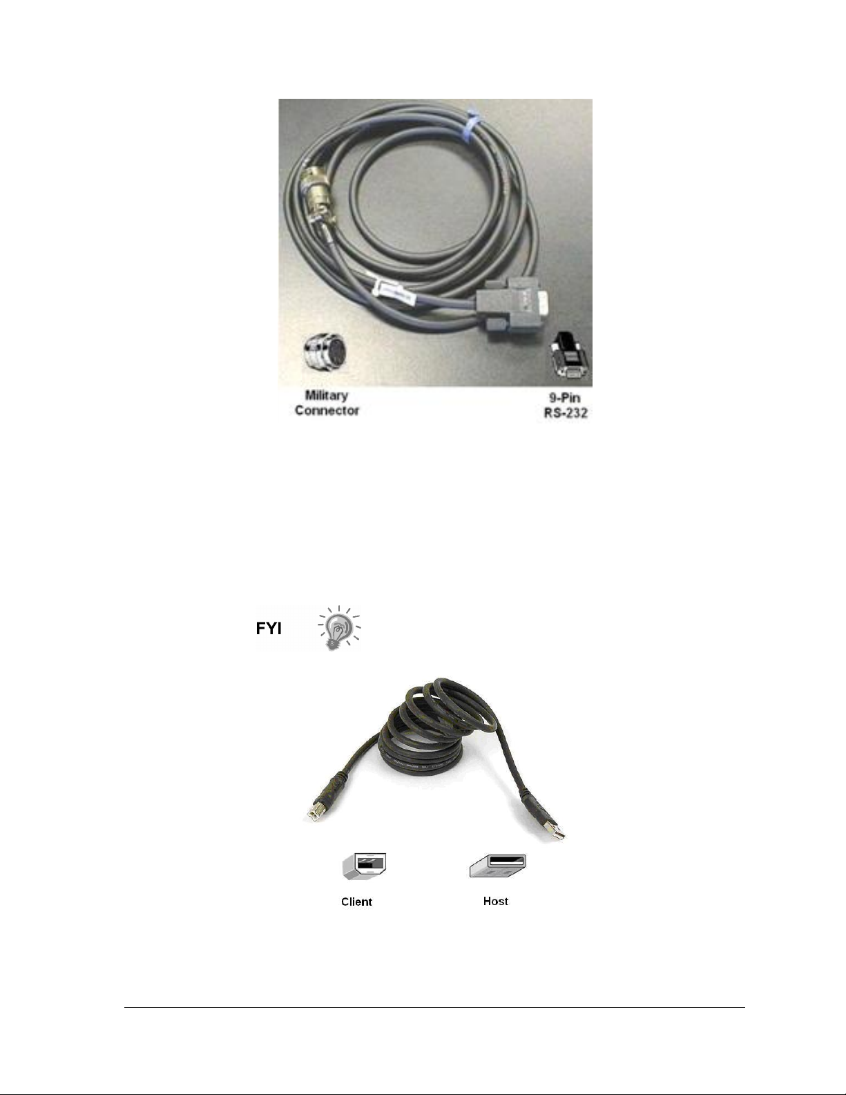
Figure 1–19 RS-232 Local Communication Cable
1.5.2 PCCU32 USB Connection
The local USB connection requires use of a USB cable connected to the host
computer (generally a laptop). A USB PCCU cable is required to connect the host
computer to the meter’s client connector (see Figure 1–20). Connecting the PCCU
cable to the meter causes an annunciator in the LCD to display an upper case
letter “L” for local connect.
The G4 EX meter must be ordered to include USB
communication capability. A change over kit may be
purchased to adapt the G4 to serial capability.
Figure 1–20 USB Local Communication Cable
2104349-001 – rev. AB Page 1–27
Page 44
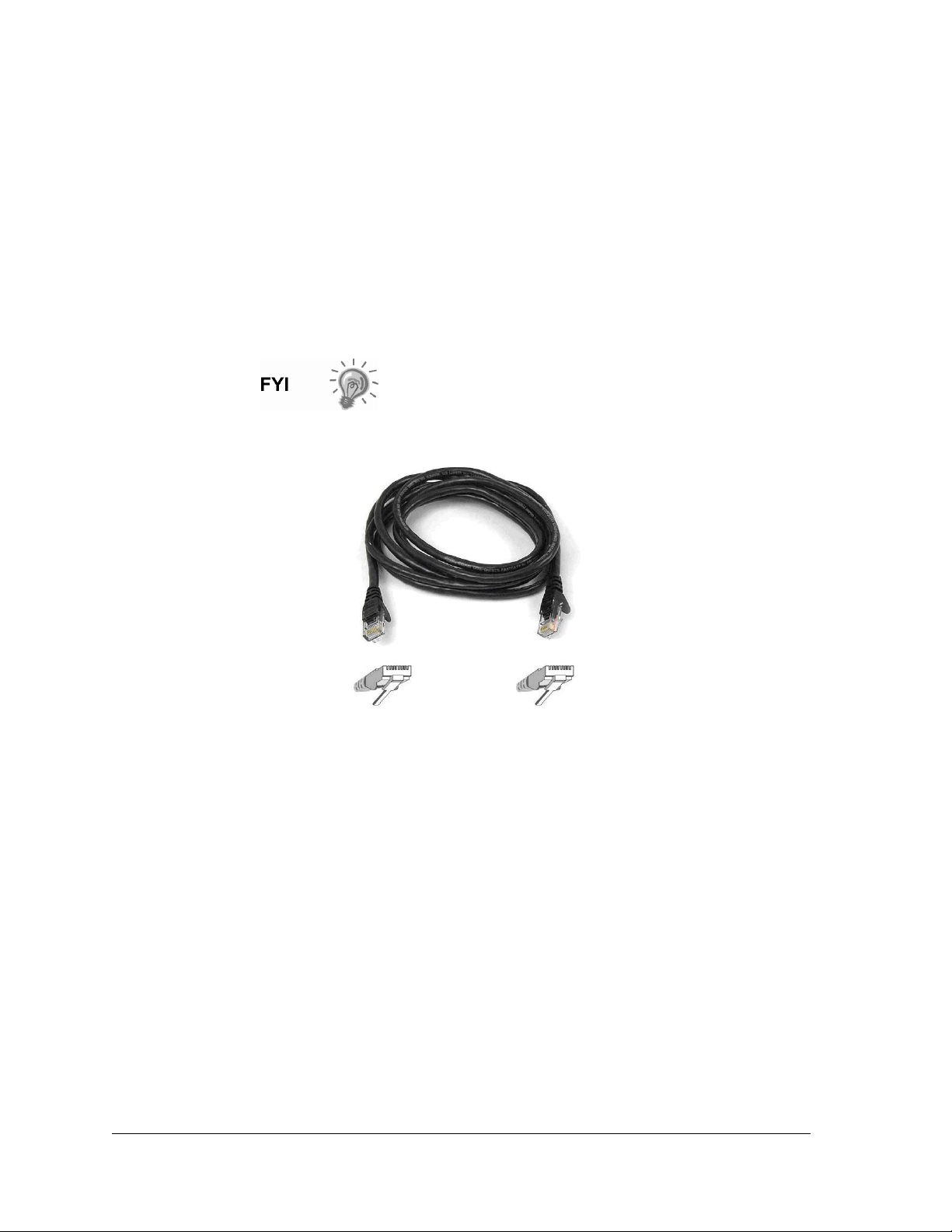
1.5.3 Bluetooth Connectivity
With the latest iteration of the G4 EX device, the user now has the option of
performing a local connecting using Bluetooth functionality. This option can be
accessed through PCCU32.
1.5.4 Network Connectivity (Dynamic IP with Router)
When the user elects to operate the G4 EX in a network environment, using an
Ethernet is a practical solution. PCCU32 communication with the meter over an
Ethernet connection (TCP/IP) requires the use of a hub, switch or router along
with the appropriate cabling (see Figure 1–22). Ethernet (local) communication in
a remote area may also be utilized.
The Ethernet option is only available by removing the end
cap on the G4 EX device.
Figure 1–21 Ethernet Communication Cable
Page 1–28 2104349-001 – rev. AB
Page 45
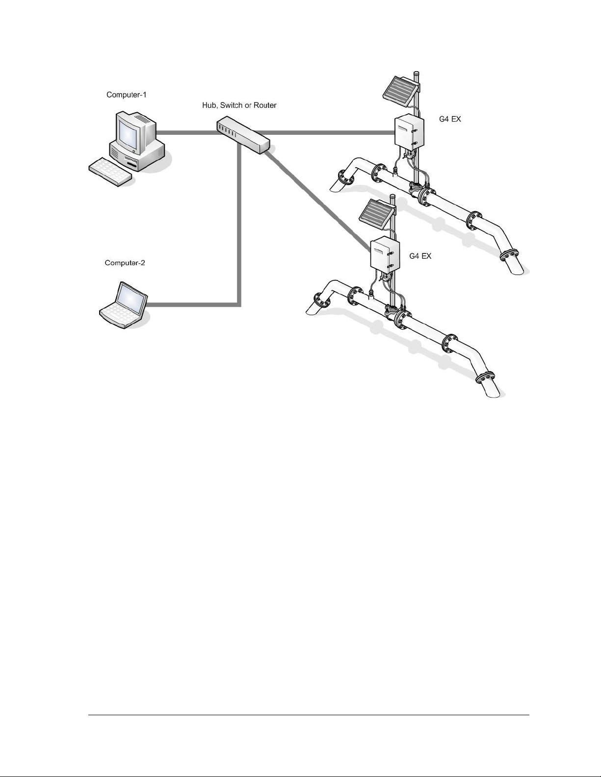
Figure 1–22 Ethernet Connectivity Diagram
2104349-001 – rev. AB Page 1–29
Page 46

Page 47

2.0 INSTALLATION
This chapter provides the user with the information for installation and setup of the
G4 EX. By the time the user has finished the chapter, they will have the G4 EX
unpacked, installed, field wired and ready for operation. For safe and trouble free
installation, follow all instructions and advisories.
2.1 Unpacking and Inspection
2.1.1 Unpacking
The G4 EX and RTD are shipped in a specially designed shipping carton which
contains the unit, mounting brackets, parts list and wiring and interconnect
diagrams. The solar panel and the battery pack with applicable hardware are
shipped in a separate carton.
Read through this chapter before beginning the installation.
This will give the user the ability to plan their specific
installation. Additionally, before beginning, refer to the
wiring diagrams delivered with the G4 EX. The user can
store these drawing under the Drawing tab in the back of
the manual.
Carefully remove the items from each carton.
2.1.2 Inspection
• Inspect the shipping carton for damage. If the shipping carton is damaged,
keep it until the contents have been inspected for damage.
• Inspect the unit’s exterior for dents, chipped paint, etc.
• Inspect the LCD window for breakage.
• Visually inspect the electronic boards, cables and EXIMV for damage.
2.1.3 Damaged Components
If any components have been damaged or if there are noticeable defects, notify
the Totalflow representative. Keep all shipping materials for the carrier’s
inspection. Totalflow will arrange for immediate repair or replacement. See the
Getting Help section at the beginning of the manual.
2.2 2” Pole Mount Installation
The following information presented in this document will detail the steps for
mounting the G4 EX to a 2” mounting pipe using the mounting kit assembly
provided with the device. The G4 EX has three mounting types that can be
performed, based on the transducer that the user has received. It must be noted
that the transducer should be mounted above the meter run to allow adequate
slope between the manifold and the orifice fittings.
The installation instructions that follow can be used for either a side pole mount or
a stand-alone pipe mount configuration.
Before beginning these steps, review the procedures and the materials required
for installation.
2104349-001 – rev. AB Page 2–1
Page 48

2.2.1 Type A
2.2.1.1 Materials Supplied
• G4 EX mounting kit assembly and associated hardware
2.2.1.2 Materials Not Supplied
• One 2” x 40” pipe
• Standard 3 or 5 valve manifold
• Stainless steel tubing
2.2.1.3 Step-by-Step Instructions
To install the G4 EX, it is recommended that two people
perform the installation. One to hold the unit in position and
the other to install and tighten the mounting brackets.
The method of installation must be consistent with the
user’s company policy.
1) Attach the pole mount bracket to the top of the 2” pipe with the U-bolts. Use
the provided hex nuts, flat washers and spring lock washers to tighten the
pole mount bracket to the 2” pipe.
Position the mounting bracket high enough on the pipe to
allow slope from the externally mounted manifold to the tap
valves.
2) Position the provided back clamp on the pole mount bracket, and align the
mounting holes between the two pieces.
3) Upon alignment, take the G4 EX and its attached transducer and set it
within the recessed groove on the back clamp.
4) Once the G4 EX and its transducer have been properly positioned, attach
the device to the brackets using the provided U-bolt. Use the hex nuts, flat
washers and spring lock washers to tighten the device to the mounting
brackets (see Figure 2–1).
Page 2–2 2104349-001 – rev. AB
Page 49
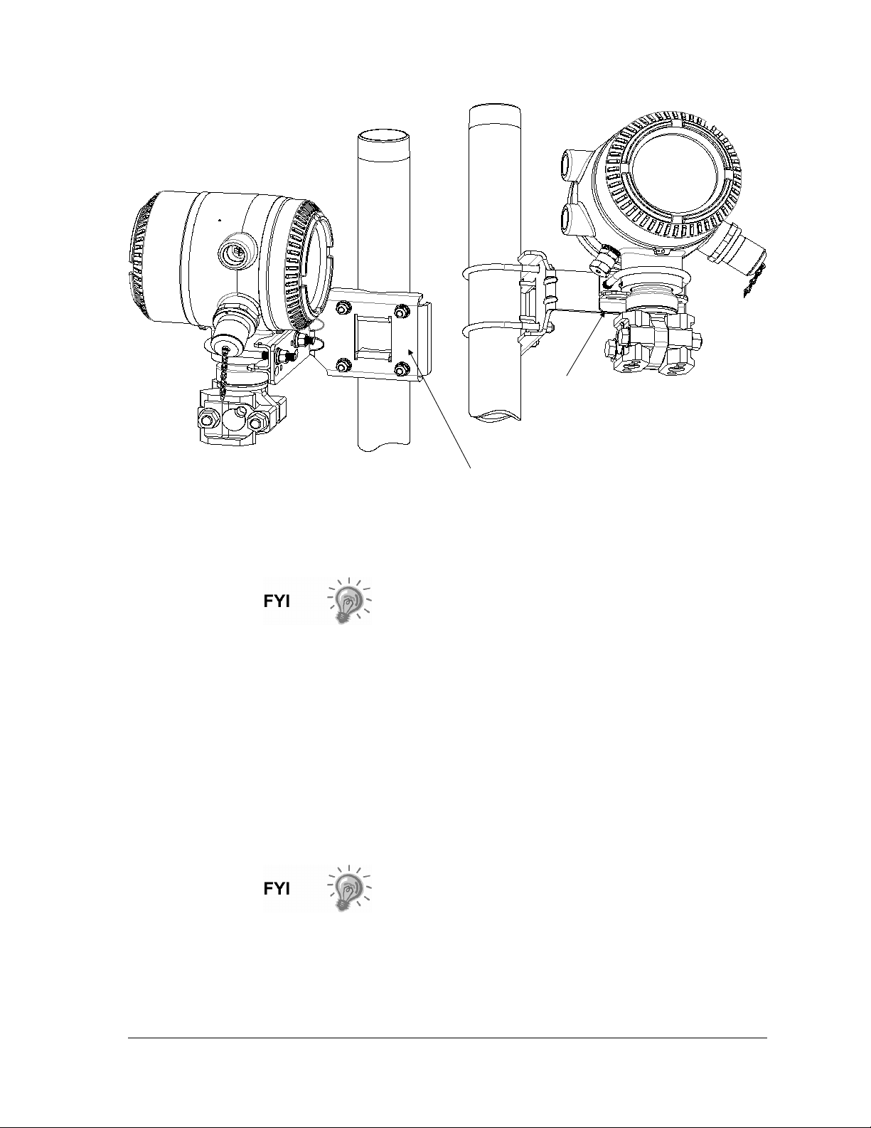
Back Clamp
Figure 2–1 Type A Installation Configuration
2.2.2 Type B
2.2.2.1 Materials Supplied
2.2.2.2 Materials Not Supplied
2.2.2.3 Step-by-Step Instructions
Pole Mount Bracket
The Type B installation configuration comes from the
factory with the transducer already enclosed in two
attached mounting brackets.
• G4 EX mounting kit assembly and associated hardware
• One 2” x 40” pipe
• Standard 3 or 5 valve manifold
• Stainless steel tubing
To install the G4 EX, it is recommended that two people
perform the installation. One to hold the unit in position and
the other to install and tighten the mounting brackets.
The method of installation must be consistent with the
user’s company policy.
1) Attach the pole mount bracket to the top of the 2” pipe with the U-bolts. Use
the provided hex nuts, flat washers and spring lock washers to tighten the
pole mount bracket to the 2” pipe.
2104349-001 – rev. AB Page 2–3
Page 50
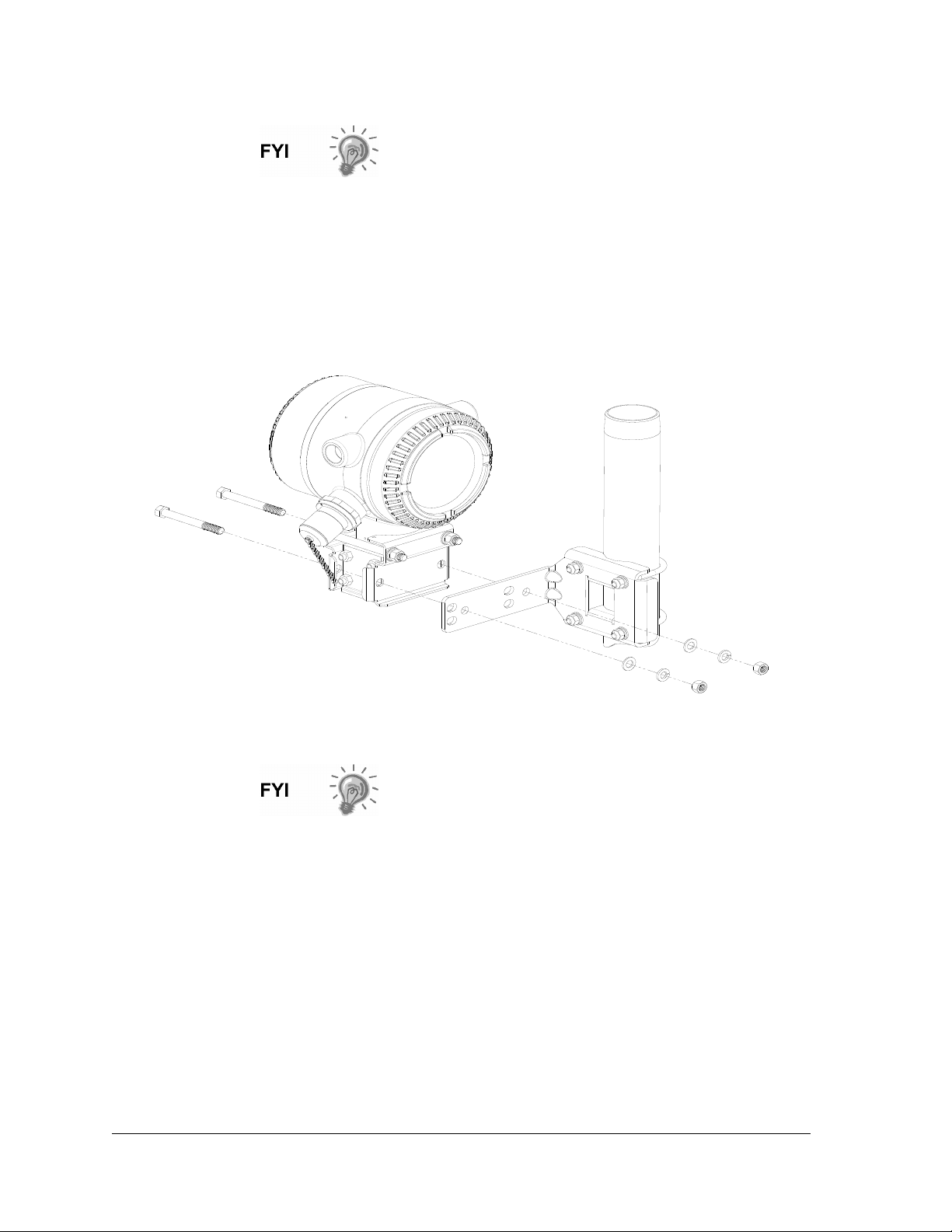
Position the mounting bracket high enough on the pipe to
allow slope from the externally mounted manifold to the tap
valves.
2) Remove the lower two hex screws, hex nuts, flat washers and spring lock
washers from the transducer’s attached mounting brackets.
3) With the associated hardware removed, align the transducer’s bottom
mounting holes with those on the pole mount bracket.
4) Upon alignment, replace the hex screws, hex nuts, flat washers and spring
lock washers through their respective mounting holes on the mounting
brackets and into the pole mount bracket. Upon completion, tighten (see
Figure 2–2).
2.2.3 Type C
2.2.3.1 Materials Supplied
2.2.3.2 Materials Not Supplied
Figure 2–2 Type B Installation Configuration
It should be noted that if this is the type of installation
configuration that the user has received from the factory,
there may be additional parts within the provided mounting
kit assembly that are not used.
• G4 EX mounting kit assembly and associated hardware
• One 2” x 40” pipe
• Standard 3 or 5 valve manifold
• Stainless steel tubing
Page 2–4 2104349-001 – rev. AB
Page 51
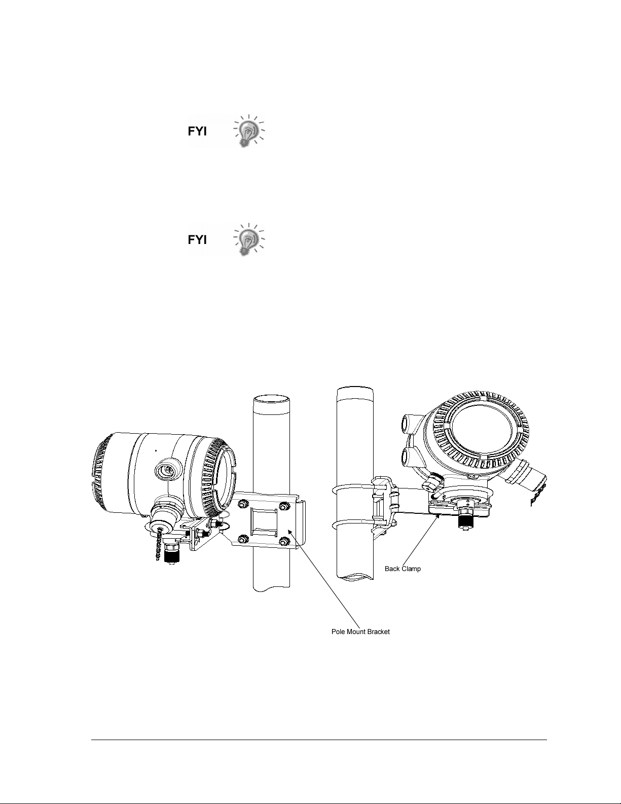
2.2.3.3 Step-by-Step Instructions
To install the G4 EX, it is recommended that two people
perform the installation. One to hold the unit in position and
the other to install and tighten the mounting brackets.
The method of installation must be consistent with the
user’s company policy.
1) Attach the pole mount bracket to the top of the 2” pipe with the U-bolts. Use
the provided hex nuts, flat washers and spring lock washers to tighten the
pole mount bracket to the 2” pipe.
Position the mounting bracket high enough on the pipe to
allow slope from the externally mounted manifold to the tap
valves.
2) Position the provided back clamp on the pole mount bracket, and align the
mounting holes between the two pieces.
3) Upon alignment, take the G4 EX and its attached transducer and set it
within the recessed groove on the back clamp.
4) Once the G4 EX and its transducer have been properly positioned, attach
the device to the brackets using the provided U-bolt. Use the hex nuts, flat
washers and spring lock washers to tighten the device to the mounting
brackets (see Figure 2–3).
Figure 2–3 Type C Installation Configuration
2.2.4 Manifold Input Lines
The following instructions provide the procedural steps to install the manifold. The
meter run manifold high (+) and low (-) pressures terminate in the transducer’s
2104349-001 – rev. AB Page 2–5
Page 52
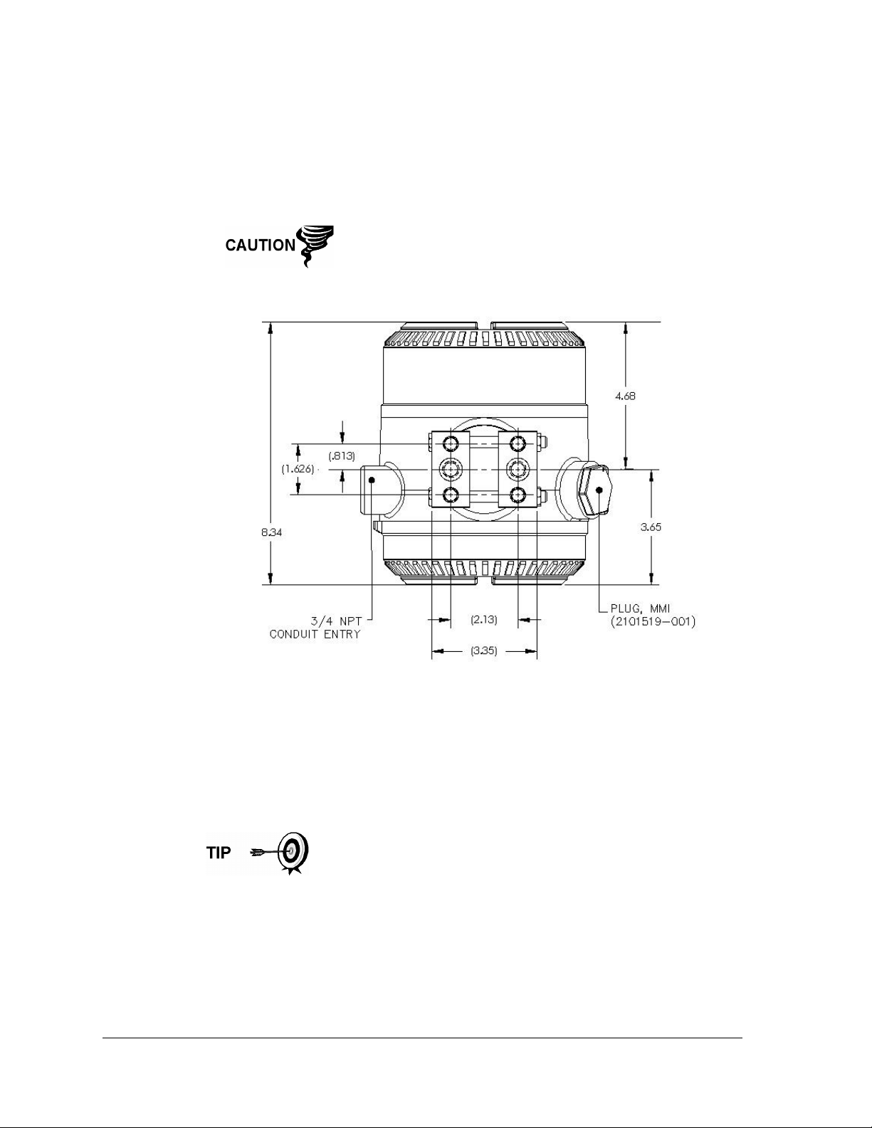
(EXIMV) + and – Differential Port cells. The Differential Port holes are located on
the bottom of the EXIMV (see Figure 2–4).
2.2.4.1 Materials Not Supplied
• Stainless steel tubing
• Tubing fittings
A backup wrench should always be used when working with
stainless steel tubing and valves. This prevents the fitting
from turning and/or putting tension on stainless steel tubing.
Figure 2–4 G4 EX EXIMV Ports
2.2.4.2 Step-by-Step Instructions
1) Install the isolation valves on the meter run.
2) Install the tubing between the meter run and the XFC. It should be noted
that the fittings are not supplied with the unit.
3) Leak check all connections.
Leaks in the tubing or manifold will introduce errors when
calibrating the transducer (EXIMV).
2.2.5 Standard RTD Probe Installation
The standard RTD measures flowing gas temperature and should only be used if
the G4 EX is located in a General Purpose area, following local codes. The
procedures that are presented in this section will enable the user to install the
RTD into the meter run.
Page 2–6 2104349-001 – rev. AB
Page 53
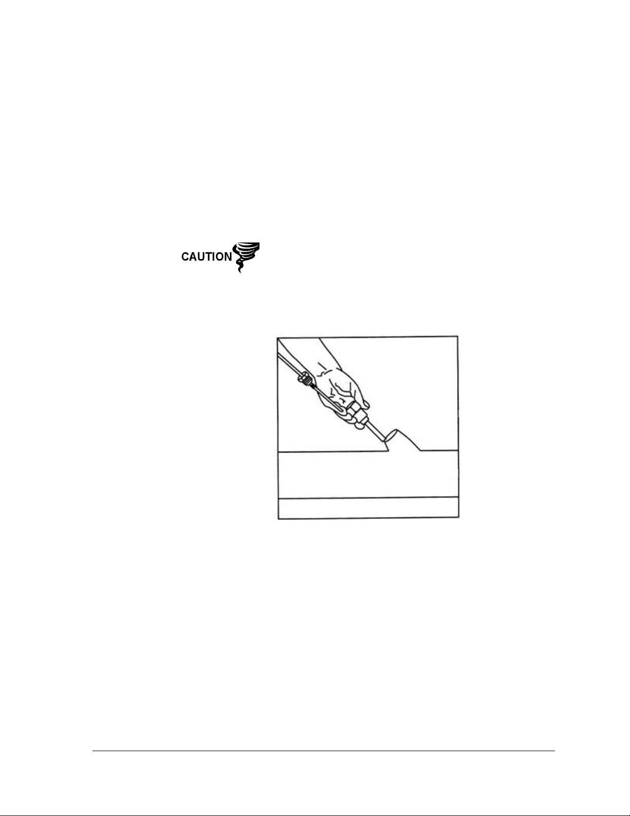
2.2.5.1 Optionally Supplied Materials
• RTD probe with 10’ of cable; optional lengths are 15’, 25’, 30’ 40’ and 50’
• One (1) thermowell with ¾” npt threads; optional threads are ½” and 1”
• Nylon tie wraps
2.2.5.2 Materials Not Supplied
• Customer must specify thermowell “U” length
• Teflon tape
2.2.5.3 Step-by-Step Instructions
1) Install the thermowell into the meter run (see Figure 2–5).
The power should be removed from the G4 EX before
performing any field wiring.
2) Using snap ring pliers, adjust the probe length so that it is spring loaded
against the bottom of the thermowell.
3) Screw the probe connector into the thermowell.
Figure 2–5 Thermowell Installation into the Meter Run
4) At the G4 EX, remove the plug from the Explosion Proof RTD hub, and
screw the adapter bushing into the hub.
5) Remove the nut from the water tight cord connector. Leave the nylon
sealing ring in place.
6) Insert the wires through the cord connector, and continue through the
adaptor bushing into the enclosure (see Figure 2–6).
7) Screw the cord connector into the adaptor bushing, and tighten.
8) Inside of the G4 EX enclosure, begin by disconnecting the connector plug
from the RTD connection, J8, to begin field wiring.
2104349-001 – rev. AB Page 2–7
Page 54
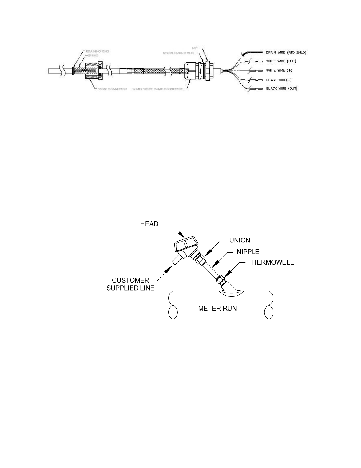
Figure 2–6 RTD Probe Wiring
9) Using the supplied wiring instructions, make the field connections to the
connector plug, and re-insert into the J8 board connector.
10) Following the connection of the RTD thermowell, secure the cable to the
meter run pipe with plastic tie wraps. Do not wrap cable around the meter
run pipe.
2.2.6 Explosion Proof RTD Probe Assembly
If the G4 EX is installed in a DIV 1 area, the Explosion Proof RTD must be used
(see Figure 2–7). The following procedures assume that the Explosion Proof RTD
kit was purchased as an option. For additional information, refer to the Wiring
Interconnect and Application Instructions that were supplied with the kit.
Figure 2–7 Explosion Proof RTD Overview
2.2.6.1 Materials Supplied
• RTD probe (see Table 1—7 in Chapter 1 for available parts)
• Optional thermowell (see Table 1—8 in Chapter 1 for available parts)
• Explosion proof connection head
• Conduit union
• Nipple fitting
• Certification tag
• Wiring instructions
Page 2–8 2104349-001 – rev. AB
Page 55
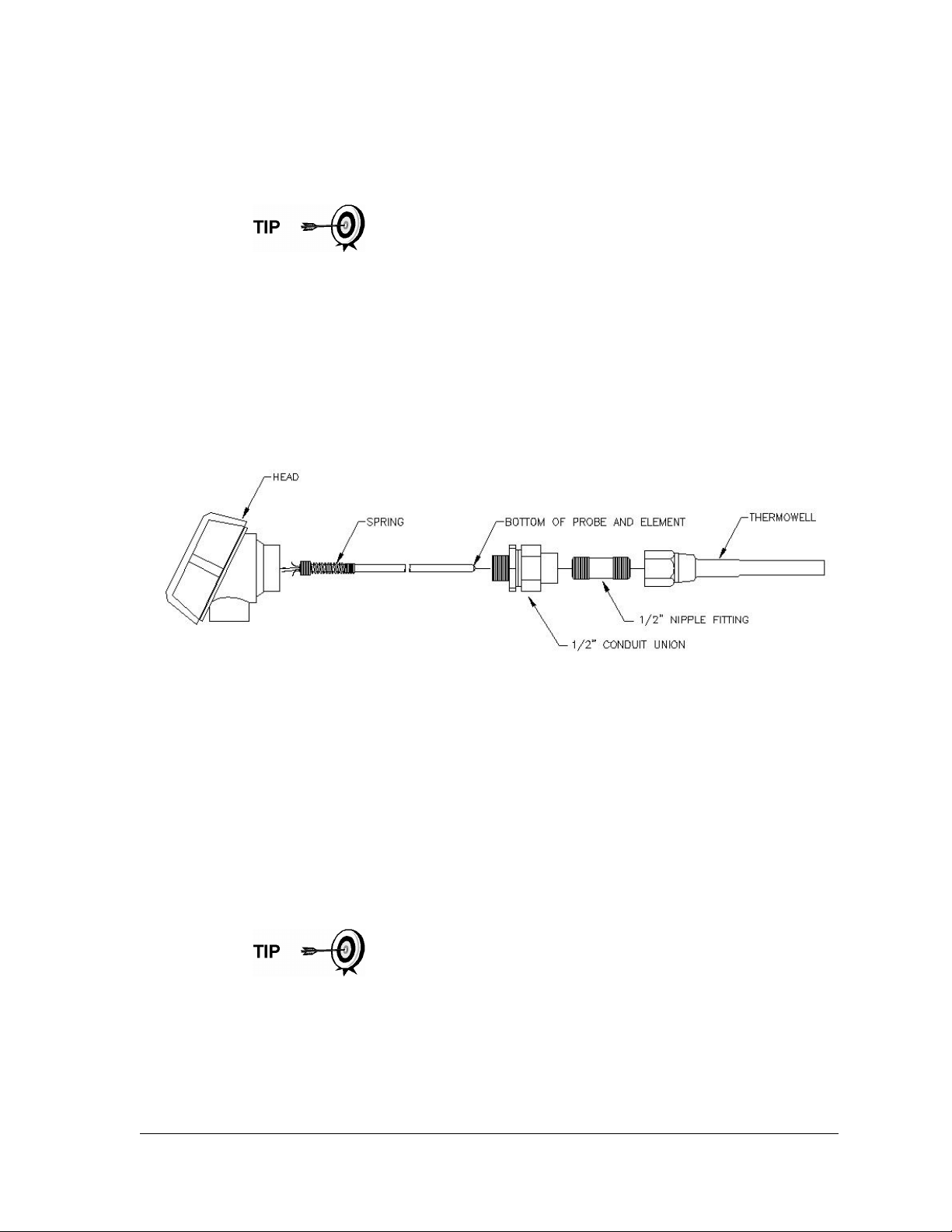
2.2.6.2 Materials Not Supplied
• Teflon tape
• Wiring cable/conduit from Explosion Proof RTD to flow computer (see local
codes for material specifications)
The following instructions assume that the thermowell has
previously been installed. The end of the thermowell should
penetrate the center 1/3 of the meter run.
2.2.6.3 Step-by-Step Instructions
1) Unpack the parts, and verify that all the supplied materials are present. If
parts are missing, contact Totalflow Customer Service at 800-442-3097 or
+1918-338-4880.
2) Screw the nipple fitting into the thermowell, and tighten (see Figure 2–8).
3) Separate the top and bottom of the union. Screw the union bottom onto the
nipple fitting. Be aware that the union nut is on the union bottom. Tighten.
Figure 2–8 Explosion Proof RTD Disassembled
4) Screw the union top into the bottom of the connection head, and tighten.
5) Unscrew, and remove the cap from the Explosion Proof Connection Head.
6) Insert the RTD probe through the opening in the head. Holding the probe
from underneath, screw the spring clockwise down into the center of the
wiring block. Stop when the top edge of the spring is flush with the top of the
wiring block.
7) Insert probe and head assembly through the bottom half of the union that
was previously installed into the thermowell. As the union halves meet, the
user should encounter some resistance. As the probe contacts the bottom
of the thermowell, the user should see the top of the probe rise (3/4” max.).
If the probe assembly is too long or too short, the user may need
to change nipple lengths.
8) Lift the union nut up to the union top. Screw together.
9) Align the RTD head to the correct position for the conduit and wiring.
Tighten the union nut.
10) Using the supplied Wiring Interconnect drawings, wire the RTD probe at the
wiring block (see Figure 2–9).
2104349-001 – rev. AB Page 2–9
Page 56

11) Following local codes, run the RTD wiring to the G4 EX unit.
Figure 2–9 RTD Probe Wiring
12) Inside of the G4 EX enclosure, disconnect power from the Termination
board. Remove the connection from J16.
13) Remove the connector plug from the RTD connection, J8, to begin field
wiring.
14) Using the supplied wiring instructions, make the field connections to the
connector plug. Re-insert into the J8 board connector.
15) Restore power to the unit.
2.2.7 6270 Optional Equipment Unit (OEU) Installation
If the 6270 OEU enclosure is used, it may be configured to include other options,
including but not limited to, a battery pack to provide power to the G4 EX,
communication equipment and solar panel charger.
Following local codes for installation, this unit would normally be located in a DIV 2
or General Purpose area. The unit may be mounted on a 2” pipe or mounted on
flat surface such as a wall.
The battery and solar panel are packed and shipped separately from the 6270
OEU. Before installation, inspect all power cables where they terminate and
connectors for damage.
Before beginning, review the procedure and the materials required for installation.
The 6270 OEU system with battery and solar panel is rated
for Class I, Division 2 locations only or can be installed in
non-hazardous locations.
Page 2–10 2104349-001 – rev. AB
Page 57
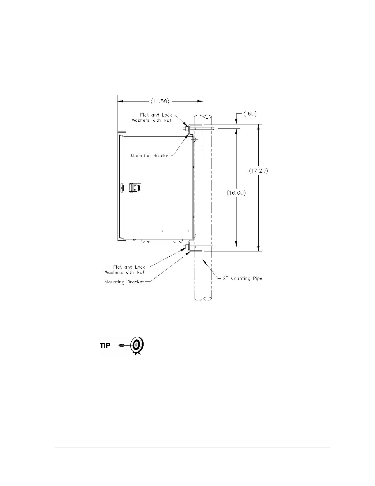
2.2.7.1 Pipe Mount
Enclosure mounting brackets and fastening hardware are supplied with the unit.
The customer must provide a 2” pipe of suitable length (see Figure 2–10).
If a charging source, such as a solar panel, is desired, this procedure may be
configured to mount the solar panel on the upper portion of the pipe.
Figure 2–10 6270 OEU Pipe Mounting Installation
Step-by-Step Instructions
Instructions assume that the user has completed the installation
of the 2” pipe.
1) Using the instructions supplied with the mounting kit, attach the bracket to
the back of the enclosure unit.
2) Position the unit on the 2” mounting pipe, and secure in place with two U-
bolts, flat washers, lock washers and two bolts (see Figure 2–10).
2.2.7.2 Wall Mount
Before beginning, review the procedures and the materials required for
installation. A typical installation should look similar to Figure 2–11.
2104349-001 – rev. AB Page 2–11
Page 58
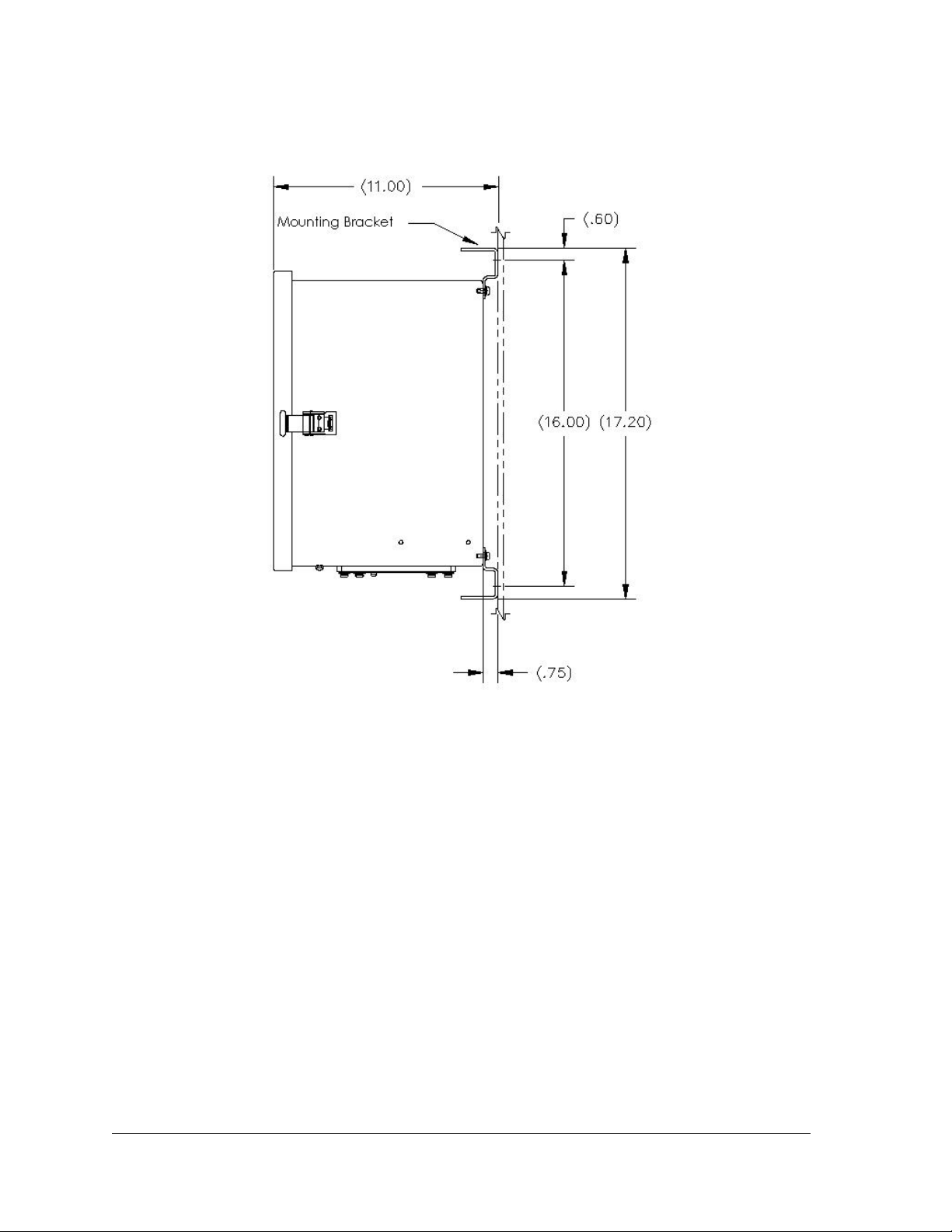
The enclosure mounting brackets and fastening hardware are supplied with the
unit.
Figure 2–11 6270 OEU Wall Mount Installation
Step-by-Step Instructions
1) Using the instructions supplied with the mounting kit, attach the bracket to
the back of the enclosure unit.
2) Prepare the wall surface for mounting, and mount the enclosure to the wall.
2.2.8 Battery Pack Installation
If the 6270 OEU is used (see Figure 2–12) and is configured to include a battery
pack, use the following procedures.
The battery is packed and shipped separately from the 6270 OEU. Before
installation, inspect the power cables that are located inside the 6270 OEU where
they terminate on the battery pack and the connector for breakage.
Before beginning, review the procedures and the materials required for
installation.
Page 2–12 2104349-001 – rev. AB
Page 59
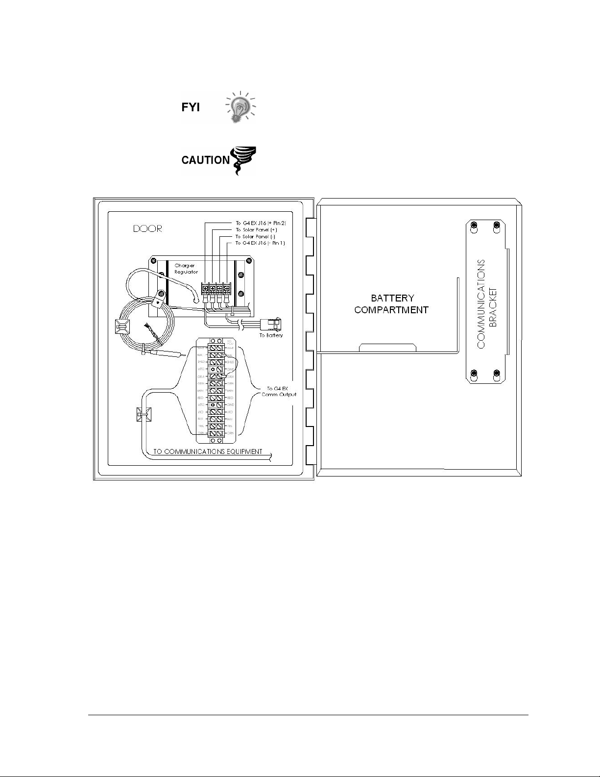
To extend the life of the battery pack, fully charge the
battery prior to installation. Systems using solar panels may
not fully charge the battery. Charging the battery fast will
remove the oxide buildup and will improve the life of the
battery.
Do not over charge the battery pack.
Figure 2–12 6270 OEU Enclosure
2.2.8.1 Step-by-Step Instructions
1) Insert the battery pack into the battery compartment (see Figure 2–12) with
the long dimension of the battery facing outward.
2) Connect the battery pack connector to the battery connector mate that is
wired to the charger regulator.
3) If the G4 EX unit is already wired to the 6270 enclosure, the LCD screen
should display a warm start.
2.2.9 Lithium Battery Installation
The following are steps for installing and verifying the connection on the lithium
battery. The lithium battery is disabled when shipped from the factory. The user
will need to connect the battery before continuing.
2104349-001 – rev. AB Page 2–13
Page 60
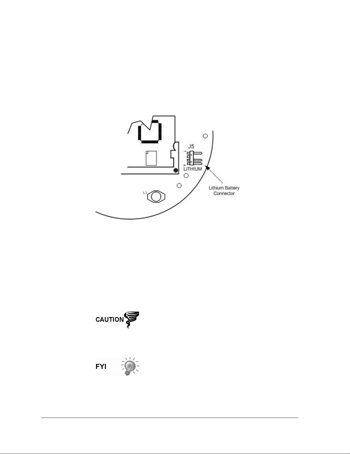
2.2.9.1 Step-by-Step Instructions
1) To connect the battery, remove the front cover of the G4 EX. Look for the
battery connector behind and to the lower right side of the display (see
Figure 2–13).
2) On the G4 EX board, the lithium (+) red is on top (pin 1) and the (-) black
(pin 4) is on the bottom. It should be noted that this is a confined space. As
such, place the ground lead of a voltmeter on bare metal, such as the plate
behind the display, and place the positive lead on the bottom solder pad. Do
not place lead against ground.
Figure 2–13 Lithium Battery
2.2.10 Solar Panel Installation
The solar panel is designed for outdoor mounting on a 2” extension pipe installed
on the upper end of the 6270 OEU 40” mounting pipe (see Figure 2–14). The solar
panel must be mounted within 12 feet of the 6270 enclosure (other lengths
available). For wall mounted enclosures, it can be mounted on the top or the side
of the meter house.
Do not connect the solar panel power cable to the charger
regulator that is located in the 6270 enclosure, unless the
main battery pack has been connected. Refer to the
Battery Pack Installation section.
Exercise caution when installing the solar panel so as not
to damage it.
For solar panel installations where the panel is mounted on
the top or to the side of a meter house, please insure that
the panel receives full sun all day. When mounted, the
solar panel will face up from the horizon at a 50° angle and
face in a southern direction.
Page 2–14 2104349-001 – rev. AB
Page 61
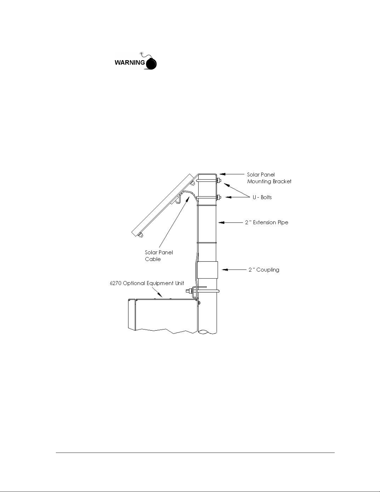
The 6270 OEU system with battery and solar panel is rated
for Class I, Division 2 locations only or can be installed in
non-hazardous locations.
2.2.10.1 Materials Supplied
• One solar panel
• Two U-bolts and fastening hardware
• Solar panel cable (if not already attached)
• Solar panel mounting bracket (if not already attached to the solar panel)
• Pipe mounting kit
2.2.10.2 Materials Not Supplied
• Cable ties
Figure 2–14 Solar Panel Installation
2.2.10.3 Step-by-Step Instructions
1) Attach the 2” pipe coupling to the top end of the 6270 OEU mounting pipe.
Securely tighten.
2) Install the 2” pipe extension into the coupling. Securely tighten.
3) Check the solar panel using the Digital MultiMeter to verify polarity and
output voltage. Voltage varies depending on the amount of sun, angle to the
sun, etc.
4) Install the solar panel on the mounting bracket, if required, with the provided
hardware. Install the solar panel cable, if required.
2104349-001 – rev. AB Page 2–15
Page 62

5) Attach the solar panel mounting plate to the top end of the 2” extension pipe
with U-bolts and associated mounting hardware. Do not tighten the U-bolts
until the solar panel has been correctly oriented.
6) For northern hemispheres, position the solar panel facing south; for
southern hemispheres, position the solar panel facing north. For optimum
charging, the solar panel should not be in shadows for any portion of the
day. The panel should be kept clean for maximum charging.
The sun’s orientation in the sky varies from summer to
winter. Keep this in mind when installing the solar panel to
make sure there are no obstructions during the entire year.
7) Do not connect the other end of the cable to the 6270 OEU until the main
battery pack has been connected and the user has been instructed to do so.
8) Remove the hole plug from the OEU, and install the cord connector.
9) Remove the nut, sealing ring and grommet from the cord connector. Slide
the nut, sealing ring and grommet over the end of the cable, and insert the
cable through the body of the cord connector. Leave enough of the cable on
the outside of the unit to allow the cable to dip below the level of the access
hole. This provides a path for moisture to run away from the unit to the
lowest point of the cable.
10) On the inside of the enclosure, allow enough cable to comfortably extend to
the input terminals on the charger regulator (see Figure 2–14).
11) Slide the nut, sealing ring and grommet to the cord connector on the side of
the unit, and tighten.
12) Before making connections to the charger regulator, trim the wire ends back
¼”.
13) Verify that the main battery pack is connected.
14) Loosen the securing screws on the charger regulator, insert the wire and
then retighten. Connect the solar panel (+) lead to the + terminal and the (-)
wire to the – terminal.
15) Following the connection of the solar panel power cable, secure the cable to
the 2” extension and mounting pipe cable with the provided plastic tiewraps.
2.2.11 AC Charging Unit Installation
The AC power charging unit maintains a constant voltage charge on the installed
battery pack. See Figure 2–15.
2.2.11.1 Materials Supplied
• AC charging unit
• Pipe nipple
2.2.11.2 Materials Not Supplied
• Plastic cable ties
• AC wiring, conduit (rigid or flexible)
Page 2–16 2104349-001 – rev. AB
Page 63
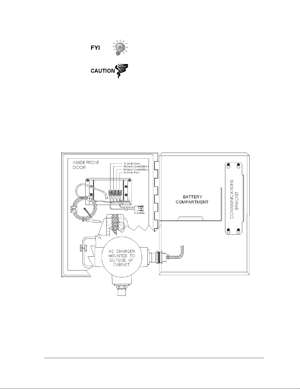
To maintain system certification, all wiring must comply
with NEC 501 code and applicable ABB certification
drawings.
To prevent injury, only a licensed electrician should install
AC power wiring to the user supplied primary AC power
source.
2.2.11.3 Step-by-Step Instructions
1) The AC charging unit is shipped separately. When the unit is received,
unpack, and inspect all components for evidence of damage. Report
damage to the shipping carrier and to Totalflow’s Service Department.
2) Remove one of the plugs from the side of the 6270 OEU so that the AC
charging unit can be mounted without obstruction. See Figure 2–15.
3) Remove the outside of the lock nut from the nipple. Leave the sealing ring
and inside lock nut.
Figure 2–15 AC Charger Installed
2104349-001 – rev. AB Page 2–17
Page 64
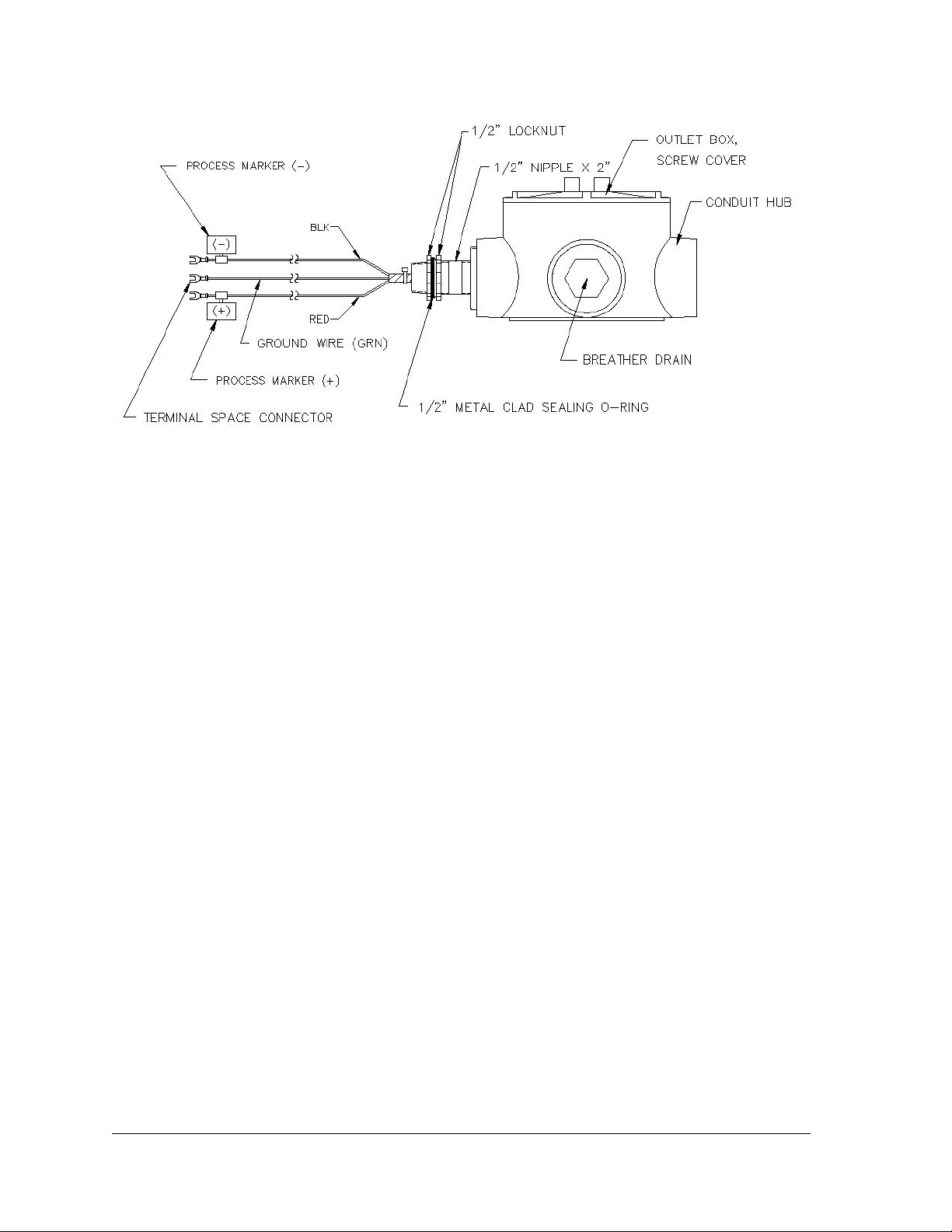
Figure 2–16 AC Charger Outlet Box Installation
4) Feed the AC charger’s DC power lines into the enclosure (see Figure 2–16).
5) Insert the nipple through the side of the enclosure, and install the removed
lock nut.
6) To prevent moisture from entering the enclosure after installing the AC
battery pack charger, be certain the “O” ring side of the metal backed
sealing “O” ring is against the enclosure.
7) Loosen the terminal screws, and insert the red wire into the plus (+) array
terminal and the black wire in the negative (-) array terminal (see Figure 2–
17). Retighten the screws.
8) Connect the green wire to one of the grounding screws that are located on
the bottom of the enclosure.
9) Pipe the conduit and associated AC wiring into the AC charger conduit box.
The AC charger is rated at either 120 VAC 60 Hz or 240 VAC 50 Hz.
Connect the 120 V hot and neutral or the two hot wires for 240 V to the
terminals of the AC charger. Connect the ground wire to the green screw.
10) Verify that the DC power wires are terminated properly inside the 6270 OEU
cabinet and that the main battery pack plug is already connected. Apply AC
power to the AC charger.
Page 2–18 2104349-001 – rev. AB
Page 65
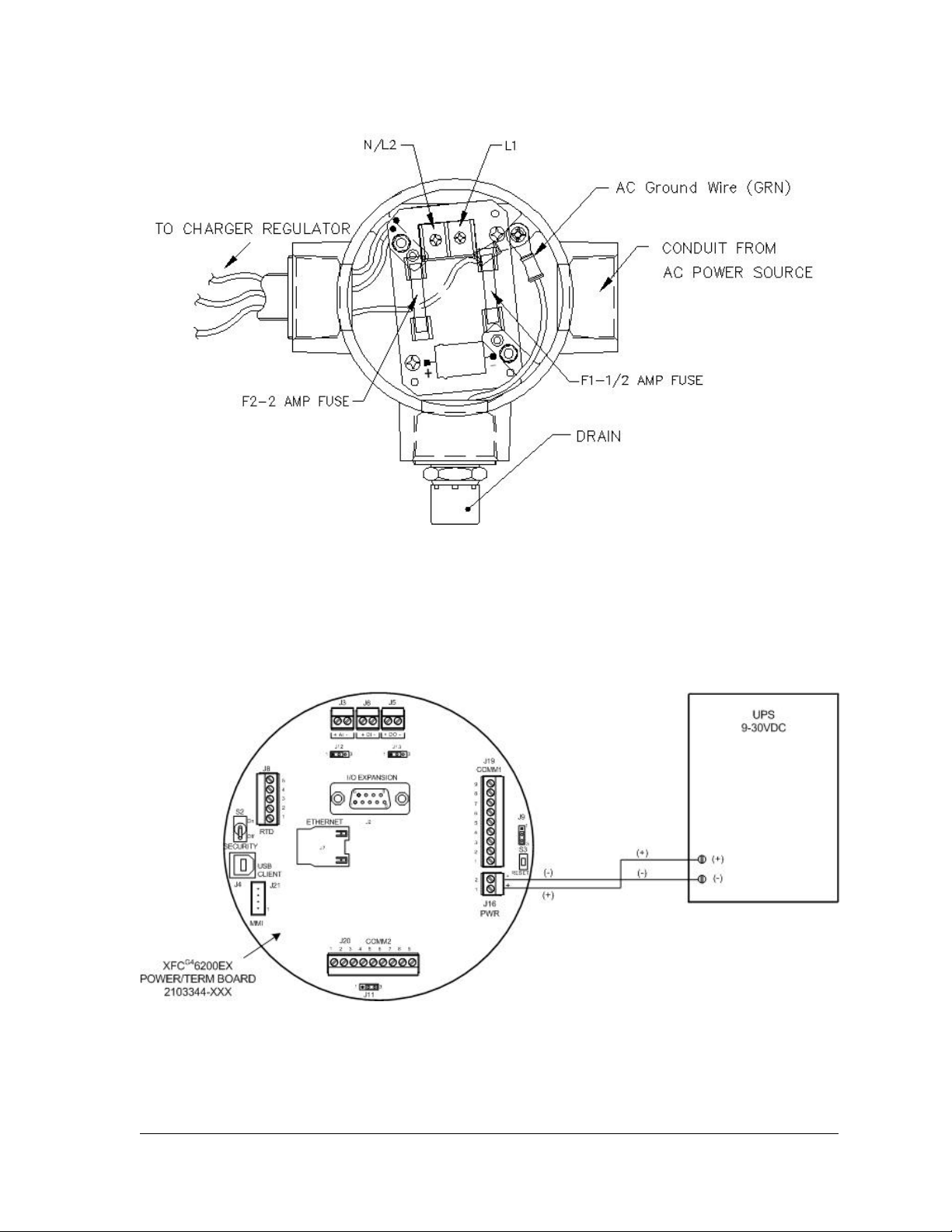
Figure 2–17 AC Charger Inside the Conduit Enclosure
2.2.12 Uninterrupted Power Supply (UPS) to the G4 EX
The G4 EX can be powered directly from any UPS that is supplying 9-30 VDC.
See Figure 2–18 for instructions on how to wire the G4 EX Termination board to a
UPS.
Figure 2–18 G4 EX to UPS
2104349-001 – rev. AB Page 2–19
Page 66

B
l
a
n
k
P
a
g
e
B
l
a
n
k
n
k
P
P
B
l
a
a
a
g
g
e
e
Page 2–20 2104349-001 – rev. AB
Page 67

3.0 G4 EX START-UP
3.1 Overview
The following chapter describes the steps required to get a newly installed G4 EX
system up and running. Specific information required to complete each step
(depending on equipment choice) is discussed more thoroughly in the PCCU32
help files.
All references in older materials to absolute pressure (AP)
have been converted to static pressure (SP). This reflects
the difference of including barometric pressure during
calibration.
3.2 PCCU32 Installation and Setup
Totalflow PCCU32 7.05.5 (or later) software is required to communicate with the
G4 EX. Previous versions of PCCU32 are not compatible.
PCCU32 software running in a laptop Windows
most capabilities for programming. The Windows environment features user
friendly help files and easy to follow menus. Easy to follow menus and icons step
the user through many required choices.
®
environment offers the user the
3.2.1 Step-by-Step Instructions
1) Insert the PCCU32 disk into the PC drive. The Install Program should
automatically load (assuming the Auto Insert Notification has not been
turned off).
If the Install Program does not automatically load, click on Start and then
Run.
• Type the CD/DVD drive letter plus ‘setup. For example: E:setup.
• Click the OK button.
2) The Install Program will load followed by a Welcome message. Click the
Next button.
3) A screen will display that asks for user information. Complete entering in the
relevant information, and enter the serial number in the appropriate space
(the user needs to ensure that they enter both the numbers and dashes for
the serial number). Click the Next button.
4) Change the destination directory, if desired. Click the Next button.
5) Change the program folder, if desired. Click the Next button.
6) The installation process will load all the required software. If the install
program asks the user to restart the computer, the user will need to do so
before running the PCCU32 software.
7) If there is no message that asks for a restart of the computer, the installation
is complete. Click the Finish button.
2104349-001 – rev. AB Page 3–1
Page 68
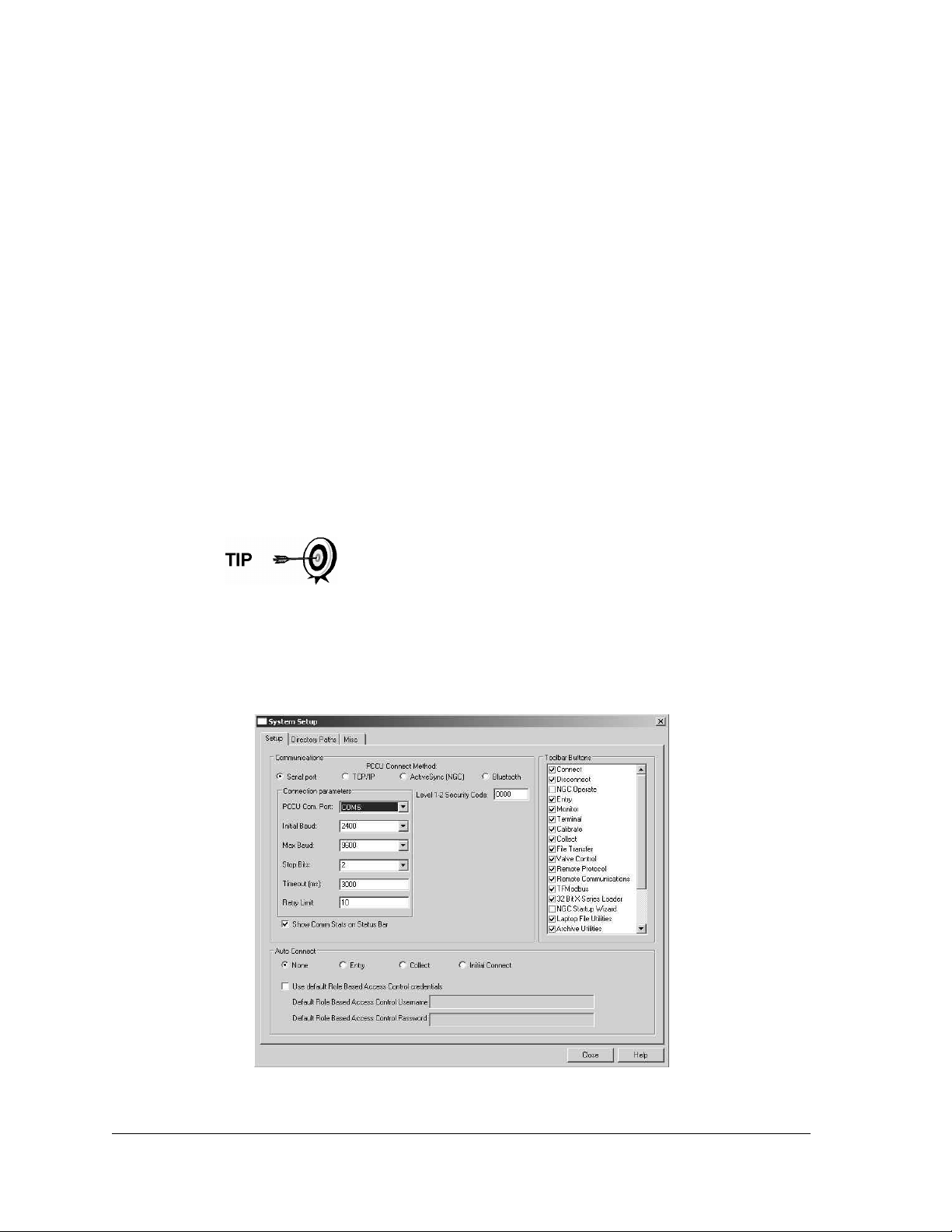
3.3 Establishing Local Communication
As discussed previously, local communication can be established in different
ways: RS-232 MMI cable, Bluetooth or USB cable. The unit can be configured for
one or the other or all. TCP/IP is available but is designed for use over a network
setup.
With each selection, the user will see options that pertain only to that connection
method.
3.3.1 Connecting to a Local Port via a RS-232 Cable
If the unit is configured to include the local RS-232 Communication port, the
connection is made using the RS-232 cable. This connects the laptop computer to
the local port on the meter.
3.3.1.1 Step-by-Step Instructions
1) Connect the MMI cable to the designated port on the PC (default is COM 0)
and to the local port located on the unit.
2) The user needs to open PCCU32. Upon selection, PCCU32 will open.
3) With the MMI cable connected, click the Connect icon on the PCCU32 main
toolbar. The Local Connect screen will display.
If the invalid security code screen displays, enter four zeroes
(0000) for the new code, and click the OK button. The G4 EX
should have defaulted to 0000 on start-up.
If the meter has been given a security code, the user needs to
ensure they have entered that code in PCCU32’s System Setup
screen (see Figure 3–1). However, if the meter has been cold
started, the security code will be reset to factory default, and
historical data will be lost.
Figure 3–1 System Setup Screen
Page 3–2 2104349-001 – rev. AB
Page 69
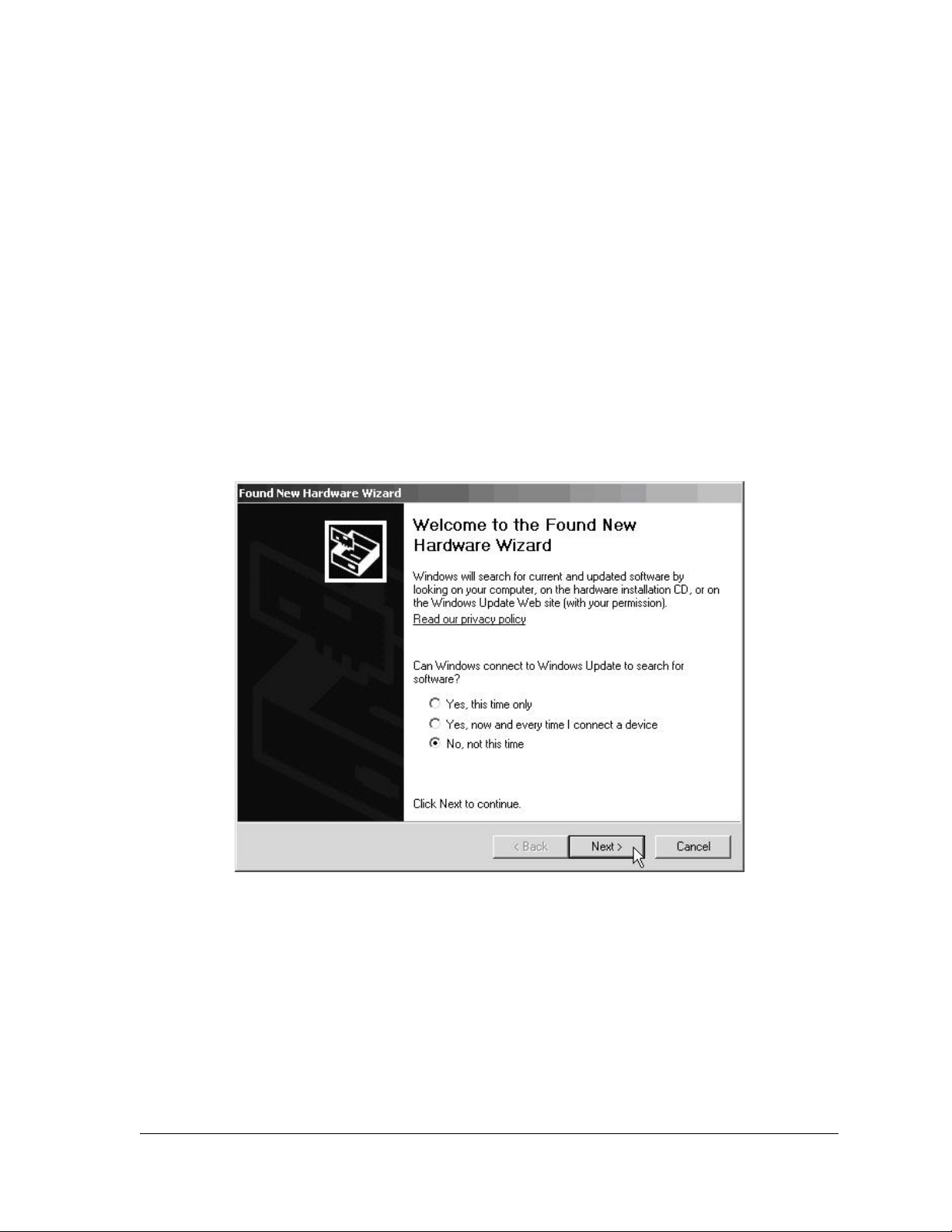
4) The Local Connect screen displays six buttons. From the button selections,
click Entry Setup to move to the Station Setup screen. Links within the
PCCU32 tree-view will move the user to screens for setup and daily
operations.
3.3.2 Connecting To Local USB Port
If the user’s unit is configured to include the local USB communication port, the
connection is made using the USB cable. This connects the laptop computer to
the Local port on the meter.
Before the user is able to communicate to the G4 EX using a USB cable, they
must install the Totalflow USB driver: Totalflow.inf.
3.3.2.1 Step-by-Step Instructions
1) If the G4 EX and laptop are powered up when the connection is made, the
user will receive the Found New Hardware Wizard screen (see Figure 3–2).
When this screen displays, the user needs to select the No, not this time
radio button. Click Next.
Figure 3–2 Windows Found New Hardware Wizard
2) To install Totalflow.inf, select the Install from a list or specific location (i.e.,
the PCCU32 folder) radio button (see Figure 3–3). Click Next.
3) Select the Include this location in the search checkbox. Browse to the
PCCU32 folder. In Figure 3–4, the folder was named PCCU605 to draw
attention to the necessity to run PCCU32 version 7.05.5 or later with the G4
EX. After browsing to the folder that contains the Totalflow.inf, click the Next
button.
2104349-001 – rev. AB Page 3–3
Page 70
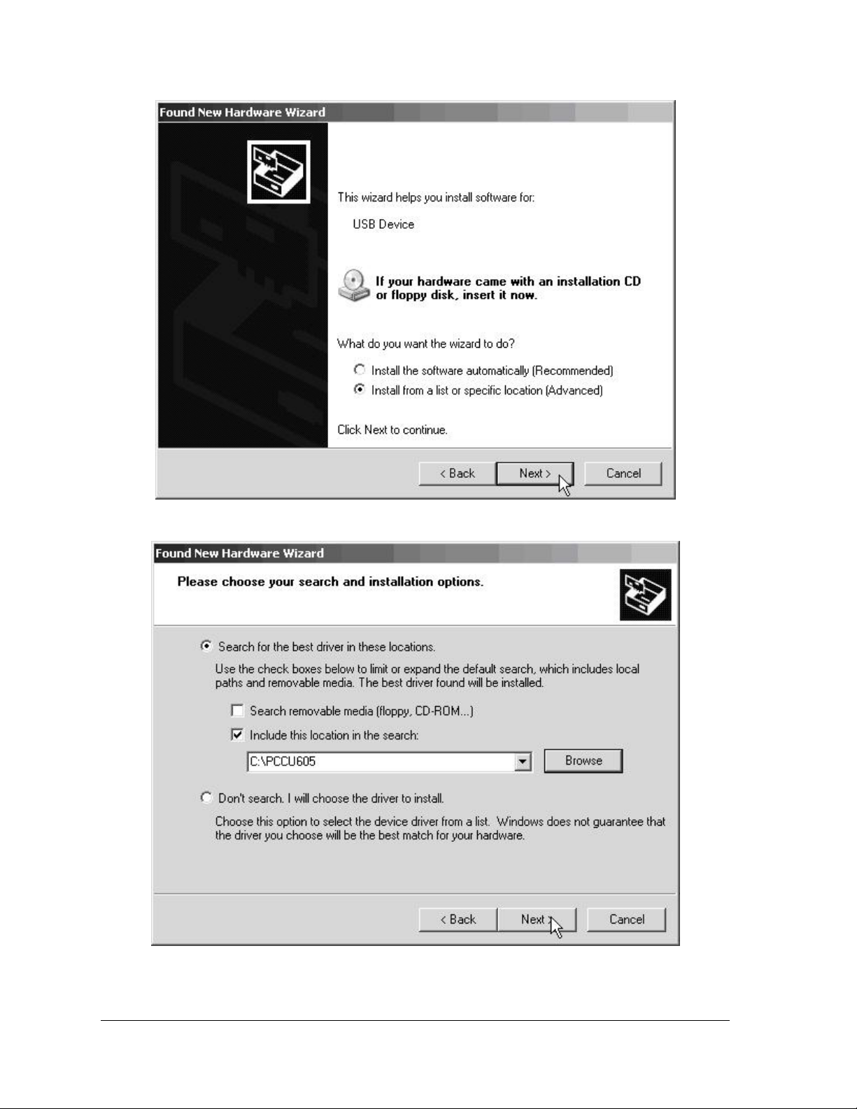
Figure 3–3 Specific Location Selection Window
Figure 3–4 Specify Location for USB Driver (Totalflow.inf)
Page 3–4 2104349-001 – rev. AB
Page 71

4) At this point, the user may receive a Microsoft message that warns that the
Totalflow USB driver has not passed Windows Logo testing. If the user
wishes to use their laptop’s USB port, they will need to click on Continue
Anyway, and proceed on with the installation.
5) The installation procedure begins loading the Totalflow.inf. This should only
take a few seconds. This will complete the Found New Hardware Wizard.
Click the Finish button. The Totalflow USB driver is now installed.
If the user sees the Found New Hardware Wizard on
subsequent connects to the meter, click the Cancel button.
6) The user will need to open PCCU32.
7) With the USB cable connected, click on the Connect icon within the
PCCU32 main toolbar. The Local Connect screen displays six buttons.
From the button selections, click Entry Setup to move to the Station Setup
screen. Links within the PCCU32 tree-view will move the user to screens for
setup and daily operations.
3.3.3 Setup of the G4 EX for Bluetooth Connectivity
The following instructions will show the user how to set up the G4 EX for Bluetooth
connectivity.
3.3.3.1 Step-by-Step Instructions
1) Plug the Bluetooth adapter into the computer. Ensure that all the relevant
drivers are installed, and the device is working properly.
2) Open PCCU32. From the PCCU32 main toolbar, select the System Setup
icon. This will take the user to the System Setup dialog box.
3) The user will need to click the Bluetooth radio button to establish that this is
the method by which they are connecting.
4) Once this has been accomplished, the screen will populate with the relevant
fields that pertain to the Bluetooth connection method. If the Bluetooth
adapter is supported by the G4 EX, the Search for Bluetooth Devices button
is activated along with a drop-down list of Bluetooth devices that have
previously been selected (see Figure 3–5).
5) The user may select a previous Bluetooth device in the drop-down list or
search for a device (see Figure 3–6). If the user searches for a Bluetooth
device, the list will contain previously paired devices and not just the
devices in range.
6) The user may select the preferred Totalflow Bluetooth device, or if that one
was not found after the search, the user can initiate another search. Upon
selection, the device will be populated in the drop-down list in the System
Setup dialog box.
7) The user must provide the Bluetooth pairing code to automate the
connection. This is typically a 4-digit authentication code set in the device
and is defaulted to 0000.
2104349-001 – rev. AB Page 3–5
Page 72
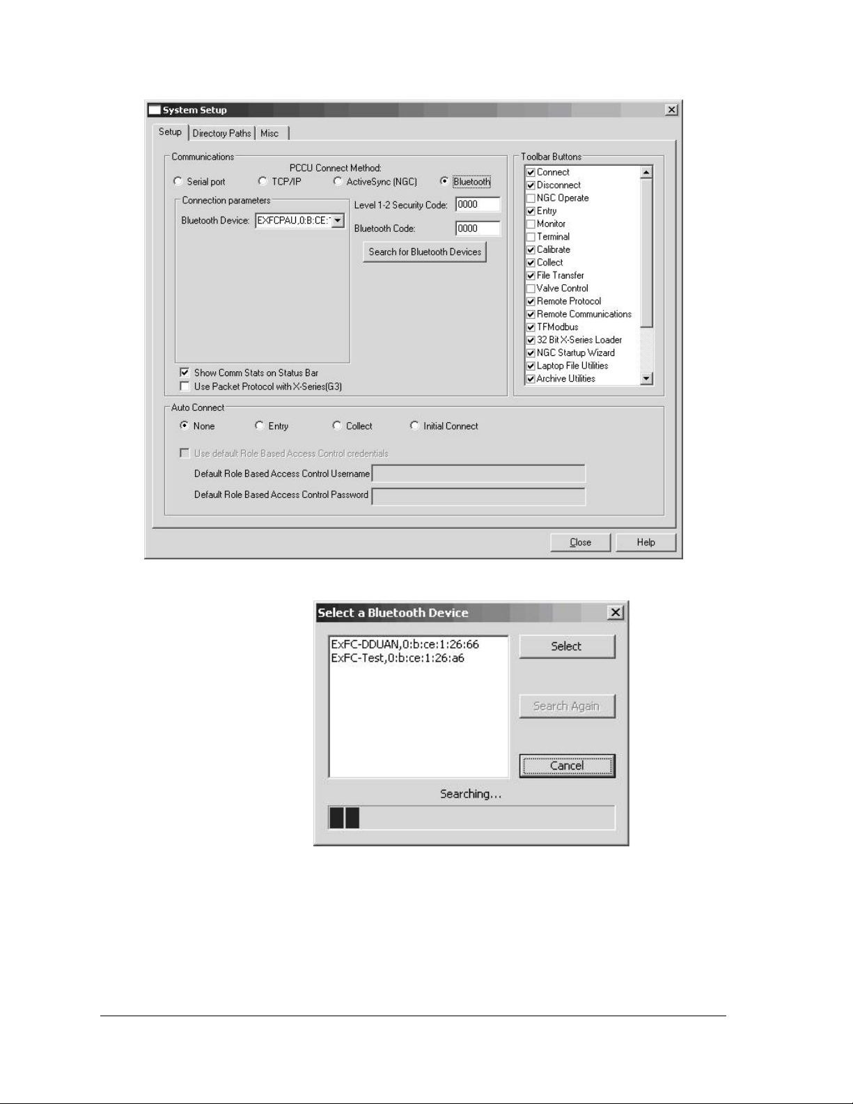
Figure 3–5 System Setup - Bluetooth
Figure 3–6 Select a Bluetooth Device Dialog Box
8) The user can close out of the System Setup dialog box, and press the
Connect button. PCCU32 will attempt to pair with the selected Bluetooth
supported Totalflow device and establish communication with it.
9) It should be noted that if the Bluetooth adapter plugged into the computer is
one that is not supported, the user will receive a different screen in the
System Setup dialog box (see Figure 3–7). At this point, the user must use
Page 3–6 2104349-001 – rev. AB
Page 73
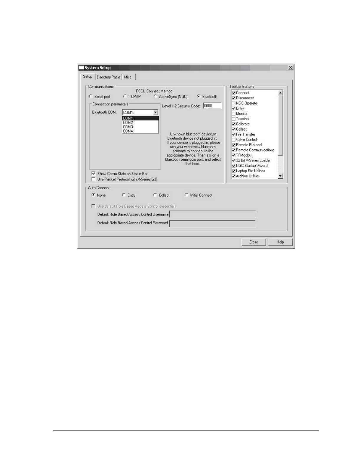
their Windows software that came with the Bluetooth adapter, and set up a
pair/connection to the preferred Totalflow Bluetooth-enabled device.
Figure 3–7 System Setup Dialog Box - Bluetooth
10) Once the pair/connection has been made, the user will need to assign a
communication port to it. After this is accomplished, the user can set the
com port in the drop-down list provided on the System Setup dialog box.
11) The user will then need to close the System Setup screen, and connect to
PCCU32 to communicate with the device.
3.3.4 Setup of the G4 EX for Ethernet Connectivity
To set up the G4 EX for an Ethernet connection, the user must first connect locally
using either the RS-232 or USB cable. Using the local connection allows the user
to setup the device for Ethernet connectivity.
Currently, there are a variety of methods for completing this task. The following
will cover two such methods.
3.3.4.1 Method One
1) Connect locally using either the RS-232 instructions or the USB instructions
covered in the previous section(s).
2) In PCCU32 Entry mode, select Communications from the tree-view. Upon
selection, click on the Network tab (see Figure 3–8).
2104349-001 – rev. AB Page 3–7
Page 74
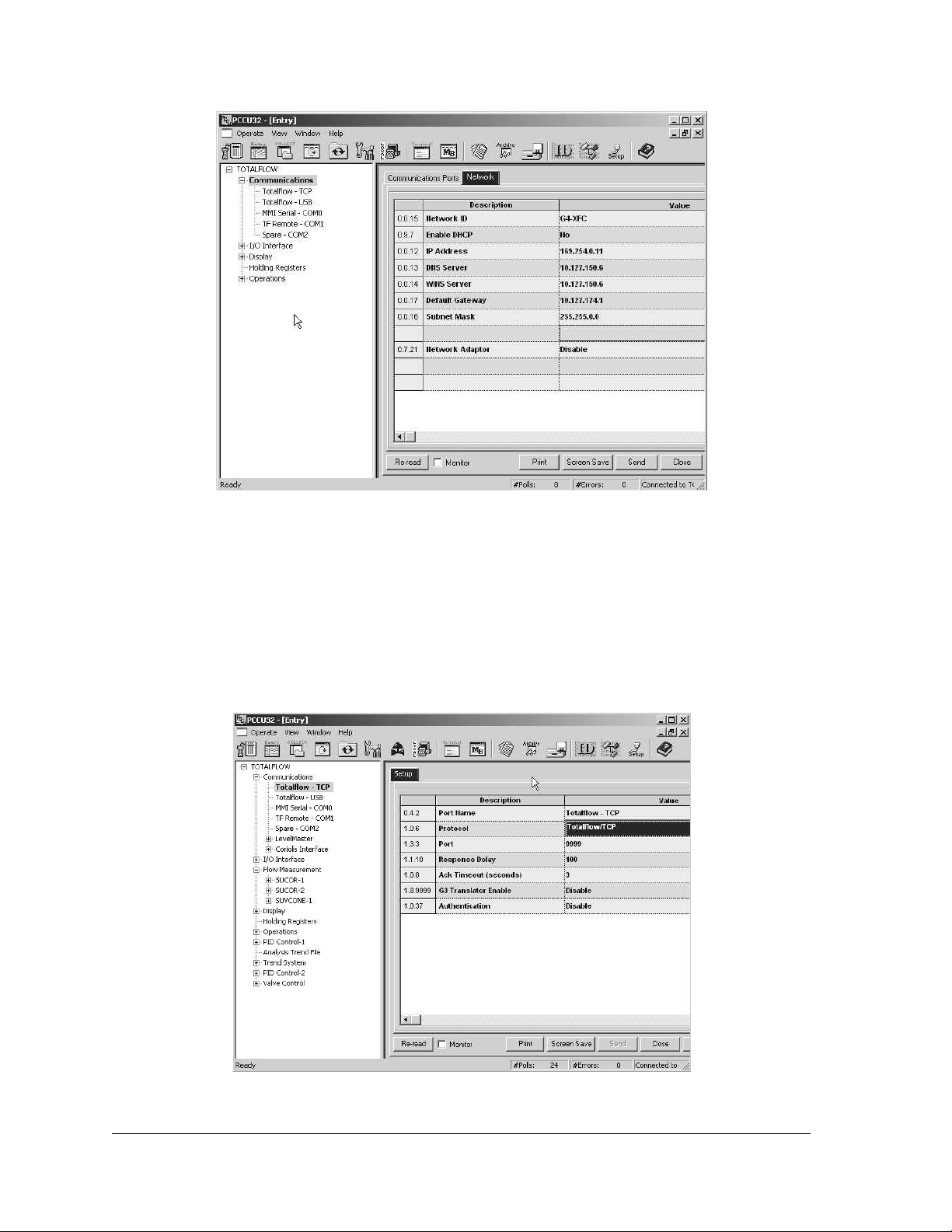
Figure 3–8 Network Tab
3) The user will need to enter a Network ID, and set the Enable DHCP
parameter field value to Yes. The other fields within the tab will autopopulate. Click the Send button.
4) Next, the user will need to locate the Totalflow – TCP selection under
Communications in the PCCU32 tree-view (see Figure 3–9). Once selected,
the user is taken to the Setup tab. In this tab, the user needs to set the
Protocol parameter value to Totalflow/TCP. When done, click the Send
button.
Figure 3–9 Communication Setup
Page 3–8 2104349-001 – rev. AB
Page 75
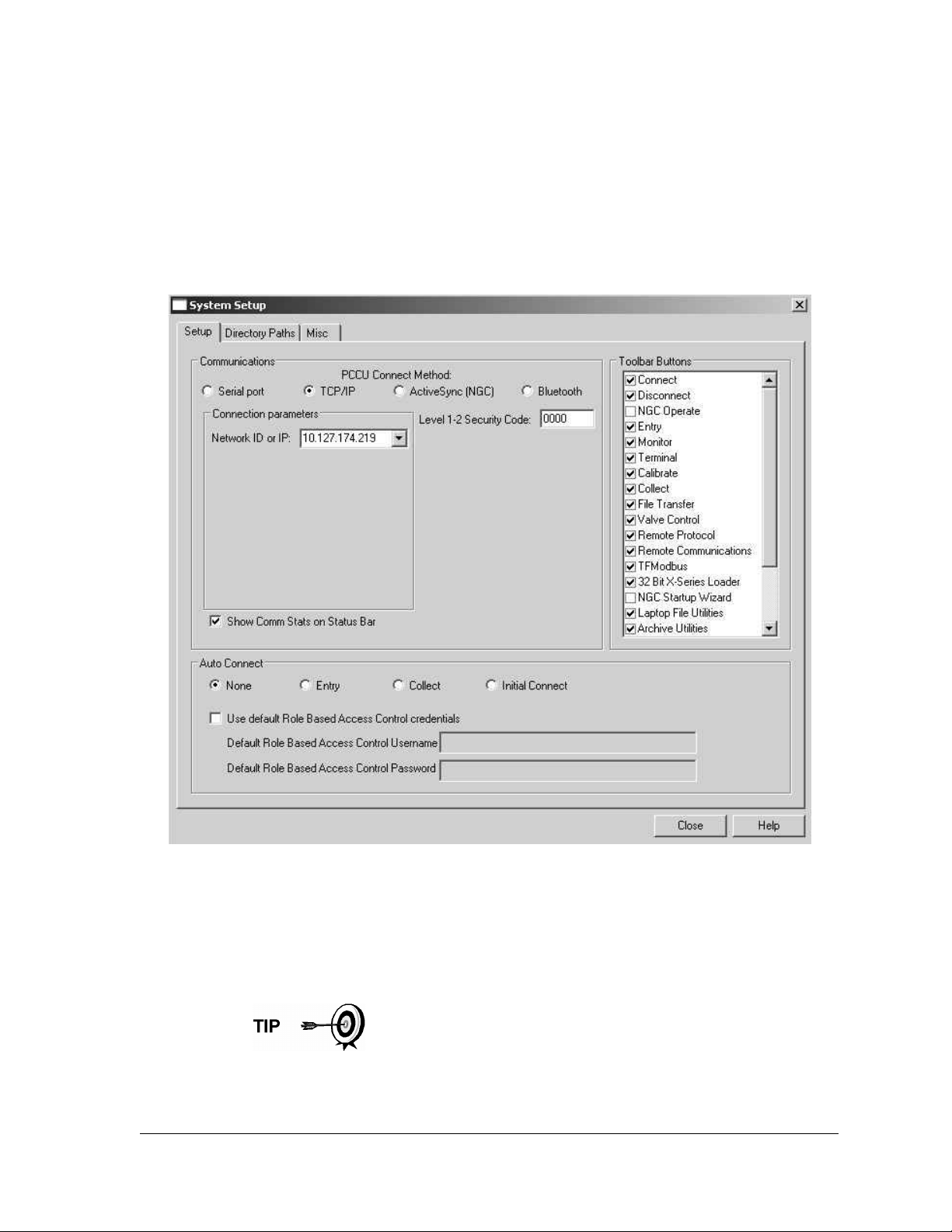
5) While still in PCCU32, the user needs to click the Operate selection on the
main PCCU32 toolbar. From the drop-down menu, select Setup. From the
fly-out menu, select System Setup.
6) Within the System Setup dialog box (see Figure 3–10), click the TCP/IP
radio button. Next, enter the network ID or IP address for the meter in the
corresponding parameter field. The network ID is the same ID that the user
entered earlier within the meter setup.
7) Upon finishing, click the Close button.
Figure 3–10 System Setup Window
8) Exit PCCU32 and the local connection.
9) With the Ethernet cabling installed, connecting to the meter is no different
than when using the PCCU cable or military connector. Click on the
Connect to Totalflow icon in the PCCU32 toolbar. To connect and move
directly to Entry mode, click on Entry instead of the Connect icon.
If the user has several meters on their network, they may find it
helpful to create a desktop shortcut for each meter. For
instructions on how to accomplish this task, follow steps 10 – 12;
otherwise, the user may continue on to the next section.
2104349-001 – rev. AB Page 3–9
Page 76
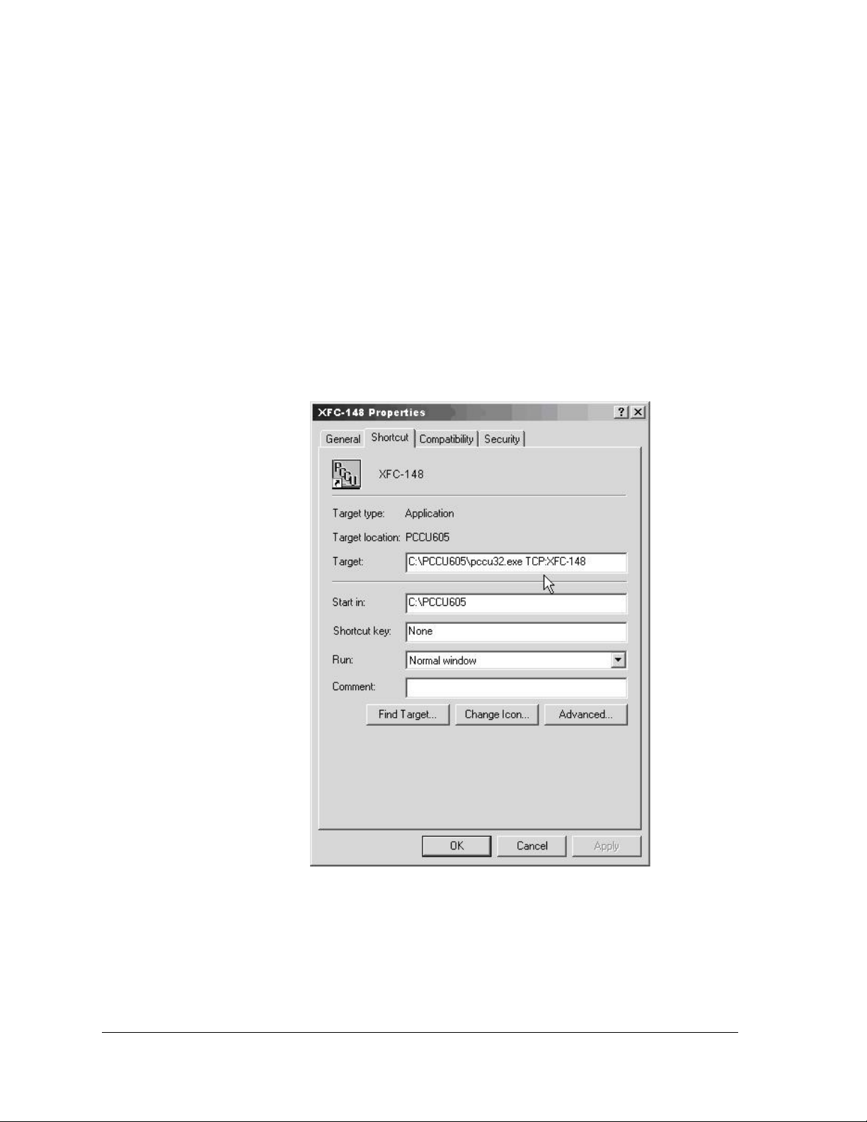
10) Create a desktop shortcut, and assign a name to it. For the sake of the
example, the following will use the meter’s ID for the shortcut name.
11) The user will now need to point to the version of PCCU32 that they want to
use (the user may have multiple versions of PCCU32 on their laptop). It
should be noted that it must be PCCU32 version 7.05.5 or later.
12) The user will then need to identify the network protocol to be used (TCP)
and the network ID (see Figure 3–11).
For example:
• Point to the folder with PCCU32 in it.
• Point to PCCU32.exe.
• Point to the protocol (TCP).
• Point to the specific network address (XFC-148).
• String the enter address together: C:\PCCU605\pccu32.exe TCP:XFC-
148.
Figure 3–11 Windows Desktop Shortcut Dialog Box
3.3.4.2 Method 2
1) Connect locally using either the RS-232 instructions or the USB instructions
covered in the previous section(s).
2) In PCCU32 Entry mode, select Communications from the tree-view (see
Figure 3–12). Upon selection, click on the Network tab.
Page 3–10 2104349-001 – rev. AB
Page 77
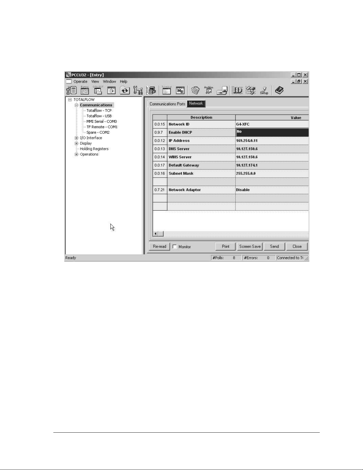
3) In the Network tab, set the Enable DHCP parameter field value to No. Click
the Send button. The remaining parameter fields within the Network tab will
auto-populate.
Figure 3–12 Network Tab
4) Move to the IP Address parameter field, and type in the IP address that is
reserved for the device. Click the Send button.
5) Close PCCU32.
6) Open the door to the unit, and locate the Reset button on the board. When
located, press the Reset button. This will set the IP address on the board.
7) The user will need to reopen PCCU32, but do not connect.
8) From the PCCU32 toolbar, click the Setup icon. This will take the user to the
System Setup dialog box (see Figure 3–13).
9) Within the System Setup dialog box, the user needs to select the TCP/IP
radio button.
10) Move to the Network ID or IP parameter field, and type in the IP address
that was established in step 4.
11) Click the Close button.
12) Reconnect to PCCU32, and move back into Entry mode. This establishes
the Ethernet connection.
2104349-001 – rev. AB Page 3–11
Page 78
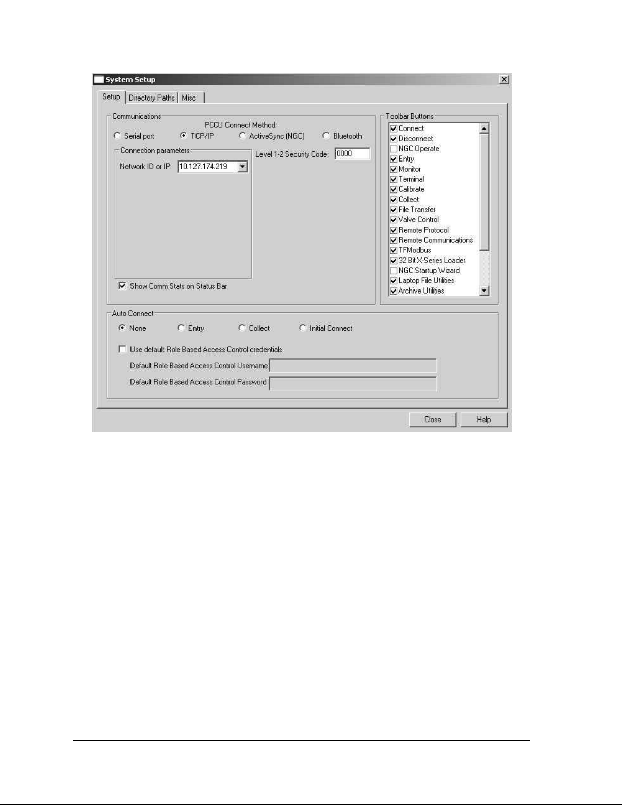
3.4 Setting Up the G4 EX
Once the user has physically connected to the G4 EX, they must then instruct the
software of the programming device to connect to. At this time, the software will
actually read the device default values that are programmed at the factory. These
preset values are based on the type of product that the user has ordered and
programmed for the most widely used configuration.
Depending on the programming device that is being used, the following are
minimum required entries. Specific information required to complete each step is
discussed in the PCCU32 help files.
3.4.1 Date/Time
The G4 EX date and time should be set before other tube parameters are entered.
This insures that events are properly dated and time tagged. Attention should be
given that the date and time are set correctly and should agree with the collection
equipment. PCCU32 or WinCCU can be used to update the date and time of the
device.
Figure 3–13 System Setup
Page 3–12 2104349-001 – rev. AB
Page 79

Description Format Note
Date MM/DD/YY Must enter 2 digits each
Time HH:MM:SS 24-hour clock
3.4.2 Station ID
The station identifier code should uniquely identify one G4 EX from that of any
others.
Description Format Note
Station ID XXXXXXXXXX 10-digit alphanumeric
3.4.3 Location
The location field can hold up to 24 alphanumeric characters to describe its
location. An example would be the lease name, county name or road number.
Description Format Note
Station ID XXXXXXXXXXXXXXXXXXXXXXXX 24-digit alphanumeric
There are additional fields stored in WinCCU for uniquely
identifying the meter, including fields for entering the lease
holder, producer, operator and buyer. These fields reside
on the host computer in the ID Manager not in the G4 EX.
3.4.4 Security System
Currently, there are three types of security that are possible:
• Device enforced legacy level 1-2 security
• WinCCU enforced legacy security
• Device and PCCU32 enforced Role Based Access RBAC security
The following sections will cover these security options.
3.4.4.1 Bi-Level Security
Data and configuration security in the G4 EX is spread across three elements: the
flow meter, PCCU32 and WinCCU32.
The G4 EX has a security switch (S2) on the Termination board. Password
security is bi-level: read only (security code level 1) or read/write (security code
level 2). To establish meter security, the user must have the security switch in the
OFF position, and locally connect with PCCU32. Enter a four digit number level 1
and level 2 security code, and click Send.
Meter Security
To establish a meter security, the user must have the security switch in the OFF
position, and locally connect with PCCU32.
1) Enter a four digit number for level 1 and level 2 security codes (see Figure
3–14), and click Send.
2104349-001 – rev. AB Page 3–13
Page 80
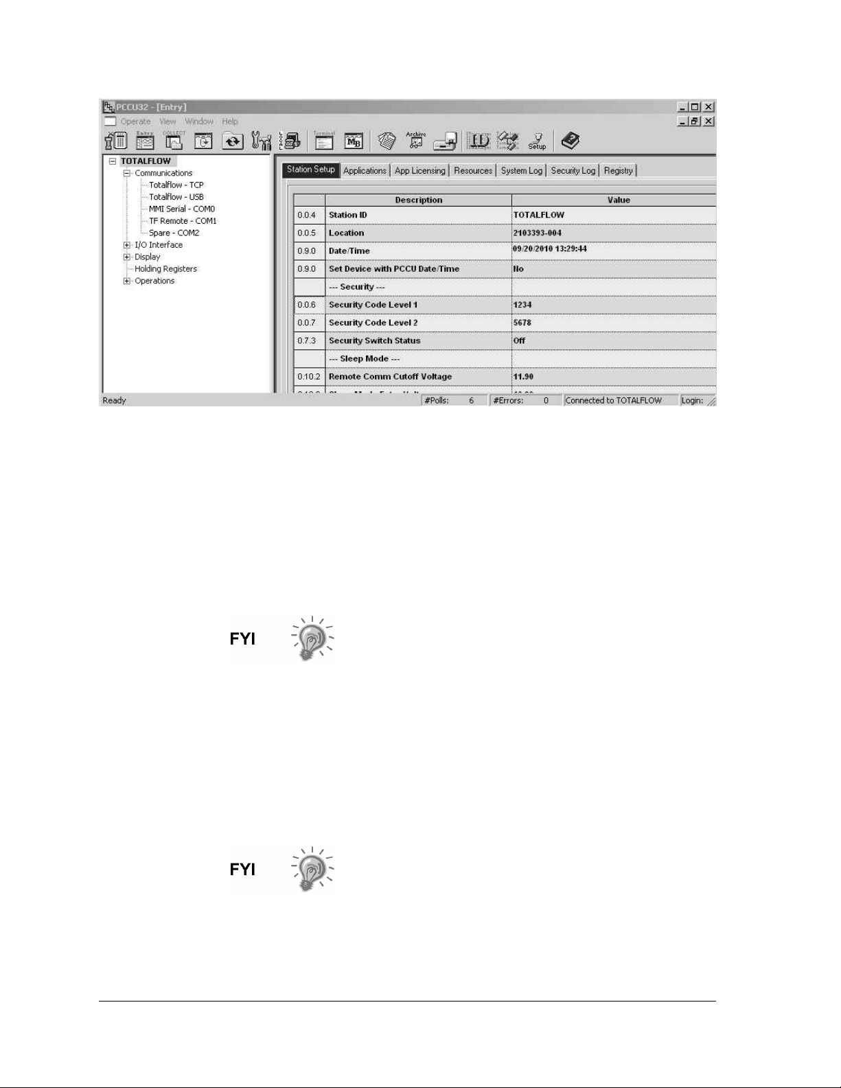
Figure 3–14 Station Setup Tab
Turning the Security Switch (S2) ON will activate the security codes. The level 1
code (in the above screenshot, 1234) will allow data and configuration values to
be read but not altered. The level 2 code ( in the above screenshot, 5678) will
allow full access to read and write.
These security codes must be entered into PCCU32 and WinCCU32 to provide
the appropriate access to the meters. However, WinCCU32 will always need the
proper security code, regardless of the position of the security switch (S2). Turning
the security switch Off does not allow unprotected access for a WinCCU32
operator.
Modbus access to the meters is not protected by the
security codes.
PCCU32 Security
PCCU32 will require the appropriate security code to be entered. To enter the
security code, the user will need to move to System Setup in PCCU32. In the
provided example (see Figure 3–15), the operator has been provided with read
only access to the meter.
The security code level of 1234 (per Figure 3-15) provides read only access to the
meter. If 5678 was entered, the user would have full read/write access to the
meter.
If the security level is breached, the meter will give no
indication. Any data that the user attempted to change will
simply remain unchanged.
Page 3–14 2104349-001 – rev. AB
Page 81
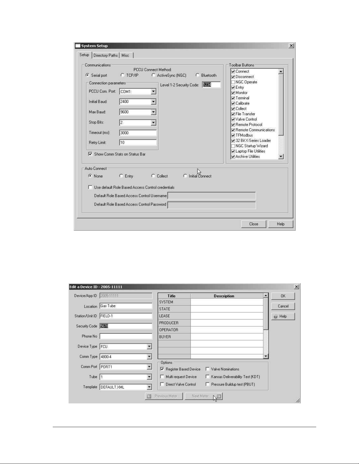
Figure 3–15 Security Setup Dialog Box
WinCCU32 Security
WinCCU32 also requires the appropriate security codes (see Figure 3–16).
Highlight the appropriate meter, and click Edit ID.
Figure 3–16 WinCCU32 Edit a Device ID Dialog Box
2104349-001 – rev. AB Page 3–15
Page 82
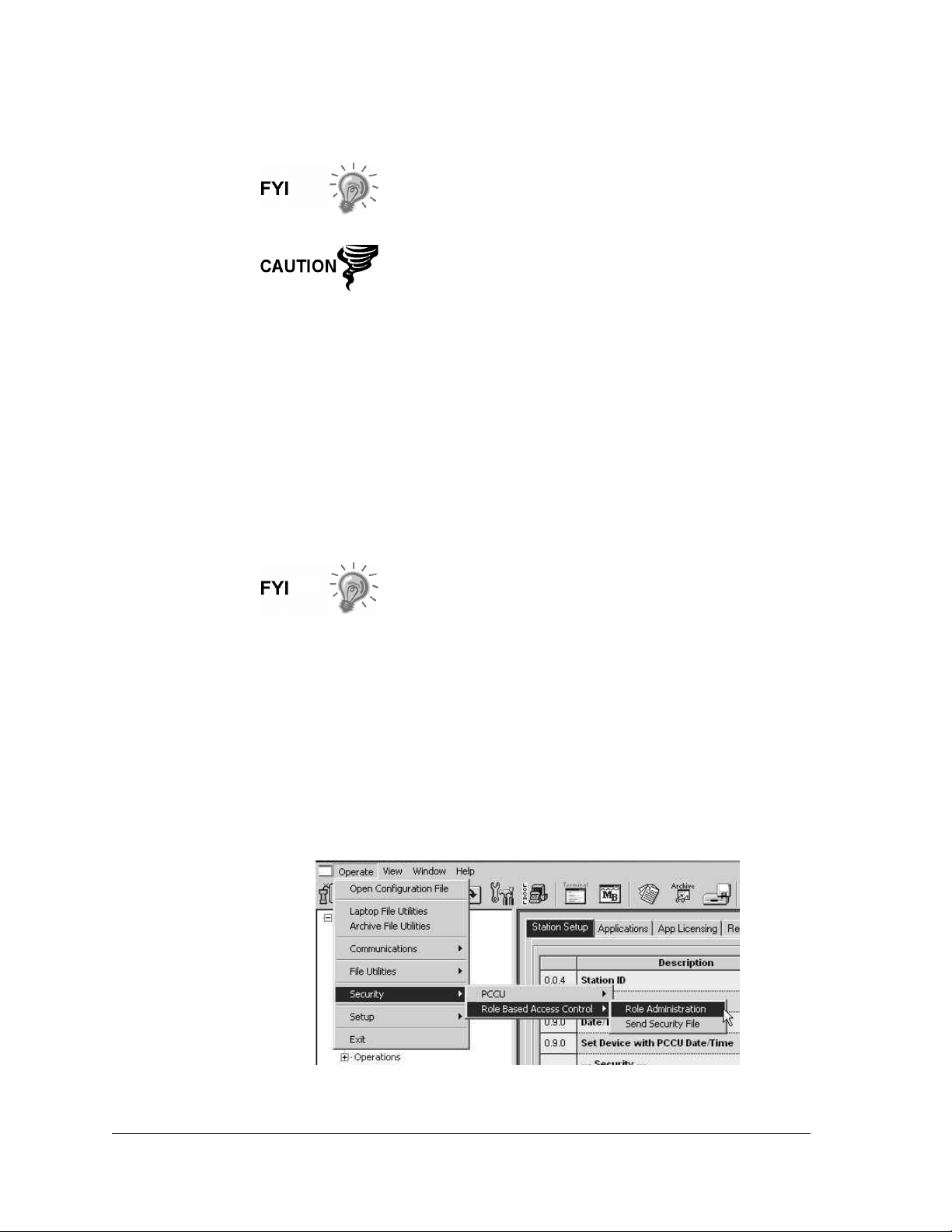
The security code level 2 of 5678 (per Figure 3–16) has been entered. This gives
the WinCCU32 user full read/write access to the meter.
Modbus access to the meters is not protected by the
security codes.
If the Security Switch (S2) on the Termination board is in
the Off position, no security code has to be entered to
access the operating parameters, even if there is one
programmed into the device.
3.4.4.2 Role Based Access Control (RBAC)
Role Based Access Control (RBAC) is a feature in PCCU32 that is designed to
allow an administrator to designate roles and control access levels to various
applications and processes in G4 devices.
Beginning with a set of default roles, it is possible to duplicate, rename and delete
these items to create a working list of access roles that are relevant to the user’s
company hierarchy. From this role list, it is then possible to create user accounts
with various assigned roles. The user is also given the ability to take the newly
created configuration and save it in the form of a security file to their PC. The
security file can then be sent to a G4 device, where it is then implemented.
RBAC is enforced by both the device and the PCCU32
interface for G4 devices. Enforcement on devices is on a
port-by-port basis. When RBAC is enforced, type 1 and 2
security is superseded.
Security File Configuration
RBAC configurations can be defined and saved in a security file. This mainly
includes Role Definition, User Configuration and Port Configuration.
The following instructions provide information for creating and editing a security
file.
1) After PCCU32 has been opened, move to the Security option under the
Operate menu option from the PCCU32 toolbar. Select Role Based Access
Control and then Role Administration from the fly-out menu (see Figure 3–
17).
Figure 3–17 Role Administration Menu Path
Page 3–16 2104349-001 – rev. AB
Page 83
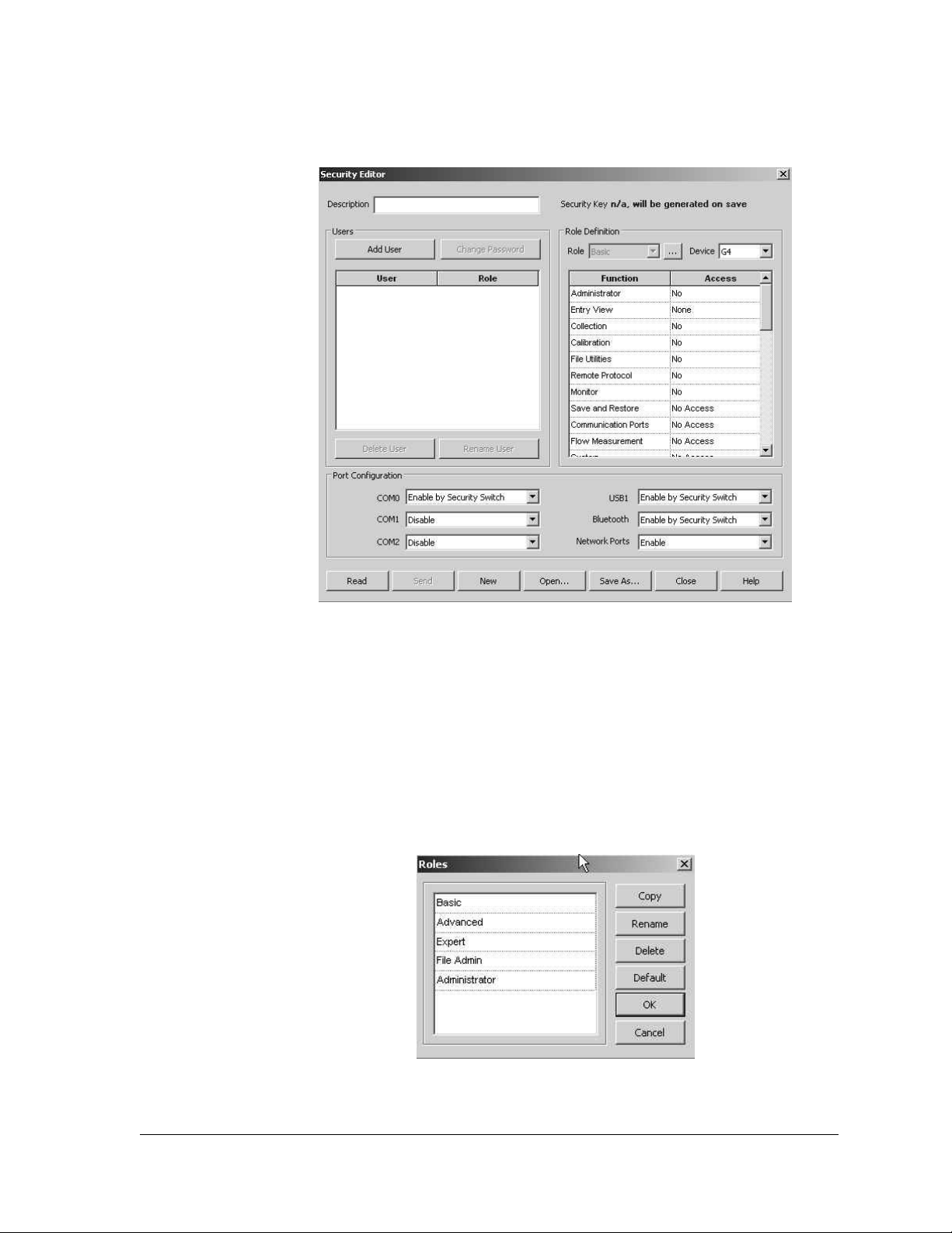
2) Once the Role Administration has been selected, the Security Editor dialog
box displays (see Figure 3–18).
Figure 3–18 Security Editor Dialog Box
RBAC security files are supported by G4 and NGC devices. The user is given the
ability to select the device type that the security file is specifically intended for.
For each role, it is possible to set the access level for each function that is listed.
The Entry View function sets the highest selectable level and has the options of
None, Basic, Advanced or Expert. Other functions have either a Yes | No option or
a No Access | Read Only | Read/Write option. If an existing role definition does not
provide the proper capabilities, a new one can be created by clicking the Browse
button next to the Role drop-down list. This brings up the Roles dialog box (see
Figure 3–19).
Figure 3–19 Roles Dialog Box
2104349-001 – rev. AB Page 3–17
Page 84
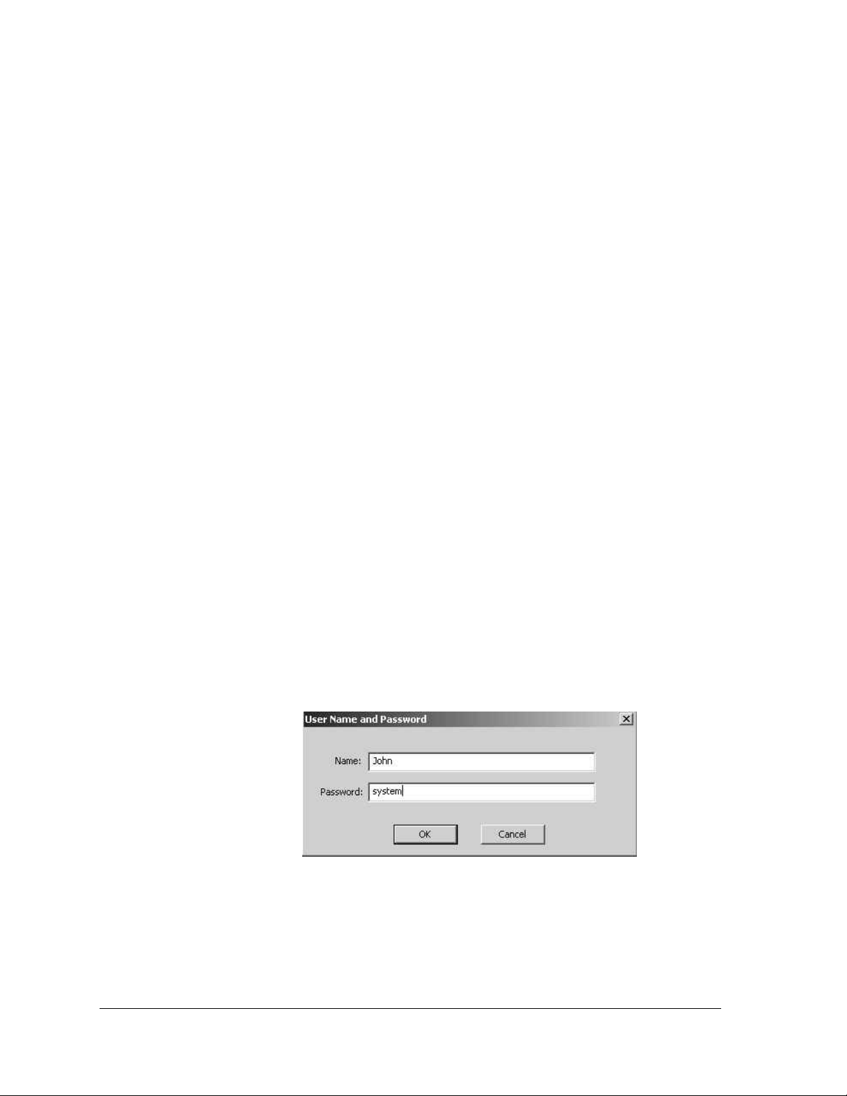
Role Definition
Default roles are automatically installed with PCCU32. These default roles are as
follows:
• Administrator
• Expert
• Advanced
• Basic
• File Admin
The Administrator role has the highest level access rights to all functions. Expert,
Advanced and Basic roles have decreasing levels of access rights.
The File Admin role has access rights of the Basic role plus minimum rights
required for sending/reading RBAC security files to and from G4 devices.
Role Creation
The following instructions will walk the user through the steps for creating a new
role.
1) Select the row that has the corresponding access level that the user wants.
Upon location, click the Copy button.
2) A dialog box displays and asks for the name of the new role. Assign a name
to the role. The new role is then available in the Roles dialog box.
3) Modify the access levels to complete the modification of the created role:
• To change the name of an existing role, select the cell, and click the
Rename button.
• To delete an existing role, click the Delete button.
• The Default button resets the Role list to the factory defaults.
User Configuration
When adding a new user, the default role is the one that is currently displayed in
the Role drop-down list at the time the Add User button is clicked. The following
dialog box displays to set the user name and password (see Figure 3–20).
Figure 3–20 User Name and Password Dialog Box
A security key is generated and displayed after the configuration is saved to a
security file. The Security Key file is displayed with “n/a will be generated on
save”, before a configuration is saved or after any modifications are made to a
saved configuration. The security key is logged in the Security Log every time the
security file is sent to a device or the device warm boots. Additionally, it can be
Page 3–18 2104349-001 – rev. AB
Page 85
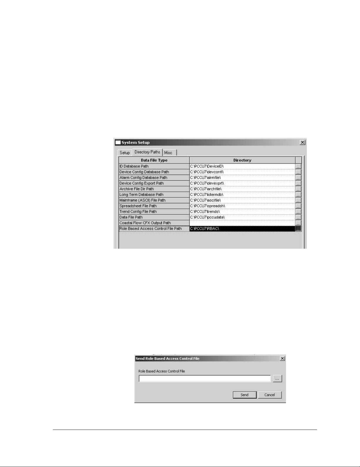
used to verify the security file on the device is the one created by the security
administrator.
The PC file name of the security file is saved in the security file and displayed in
the Security Editor dialog title bar, when the file is read from a device. It will also
be used as a default file name, suggested for saving.
The Open button opens a security file from the PC for editing (see Figure 3–18).
The New button clears all users and starts editing a new security configuration
with default roles and no users.
RBAC security files are saved with a unique extension (.rba), by default. There is
also a default directory that hosts these files. The directory is configurable by
selecting the menu item Operate > Setup > System Setup (Figure 3–21).
Figure 3–21 System Setup Dialog Box
When connected to a Totalflow G4 device, the Read button is enabled for all
users. Additionally, the Send button is enabled only for users with Administrator
rights. The Read button reads a security file from the device for editing. The Send
button is used to send and apply the security configuration to a device.
Another way to send a security file is to select the menu item (Operate > Security
> Role Based Access Control > Send Security File). This menu item is only
enabled for users with Administrator rights. Clicking the menu item displays the
Send Role Based Access Control File dialog box (Figure 3–22).
In the dialog box, the user can click the Browse button to select the required file.
Upon selection, the user can click the Send button to send the security file.
Figure 3–22 Send Role Based Access Control File Dialog Box
2104349-001 – rev. AB Page 3–19
Page 86
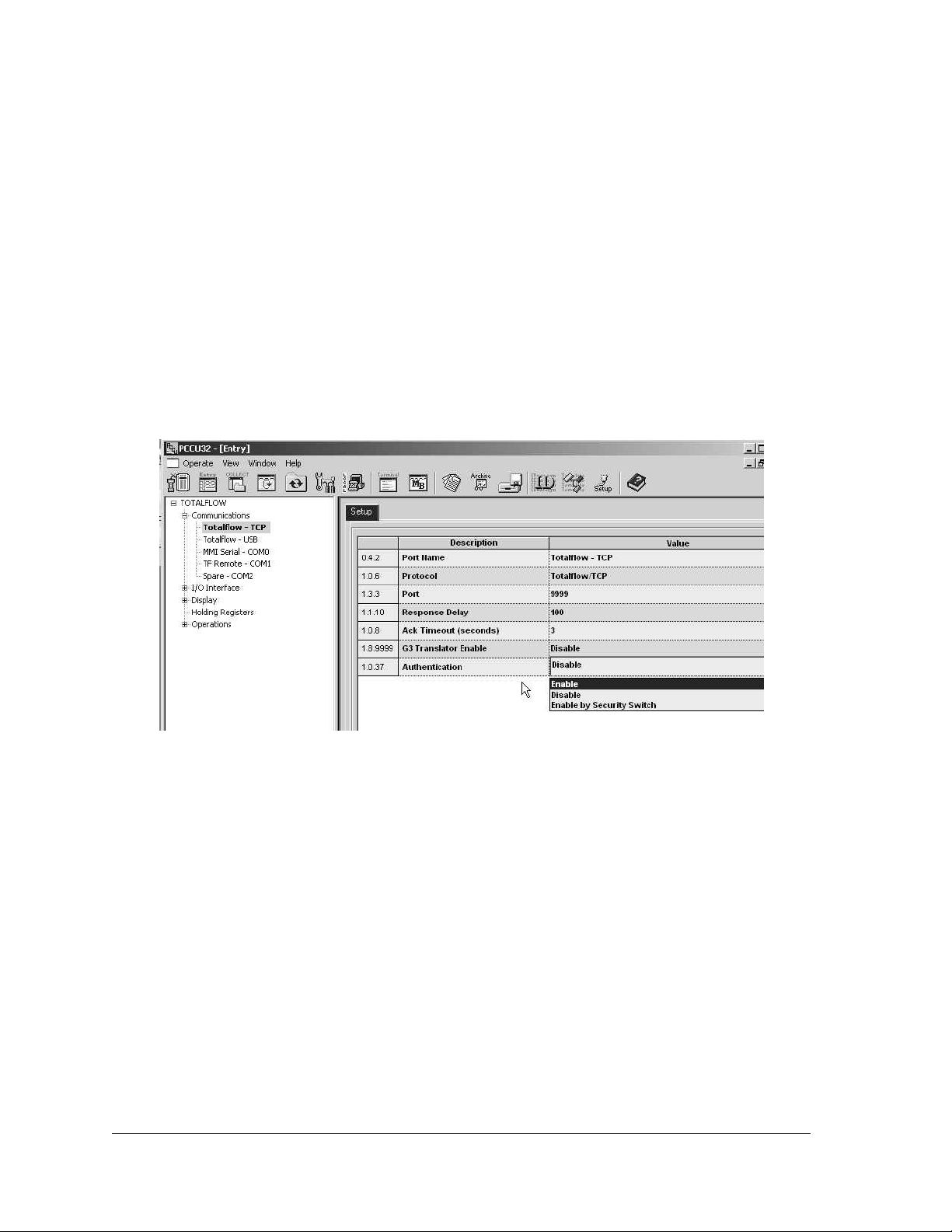
Port Configuration
Entry mode is available in the Advanced and Expert view modes and can be used
to configure RBAC for ports that are not specified in the security file or can be
used to override what is specified in the security file. Under each port which has a
protocol specified is a parameter field called Authentication. This parameter can
be set to Disabled, Enabled or Enable by Security Switch ( See Figure 3–23).
• Disabled – Does not perform any RBAC functions on the port.
• Enabled – If the administrator name and/or password are lost or forgotten, it
will be necessary to use TfLoader to delete TfCold and TfData, and then cold
start the device to gain access. This will reset the device to the default factory
configuration.
• Enable by Security Switch – If the administrator name and/or password are
lost or forgotten, RBAC may be disabled using the legacy security switch. By
setting the switch to the Off position, a user may log in and reconfigure the
security access. This will not result in the loss of any data.
Figure 3–23 Totalflow-TCP Setup Tab
User Login
When the user tries to connect to an RBAC enabled port on a G4 device, they are
first asked to login (see Figure 3–24).
The user can elect to save the user name/password as default credentials to be
used for subsequent logins. To change or disable the default RBAC credentials,
select the menu item, Operate > Setup > System Setup (see Figure 3–25).
After a security file is sent to a Totalflow G4 device, the user is disconnected from
the device and asked to re-login under the following circumstances:
• RBAC security was not enabled on the connected port before the security file
is downloaded.
• The user is not defined in the new security file.
• The user has different access rights in the new security file.
Page 3–20 2104349-001 – rev. AB
Page 87
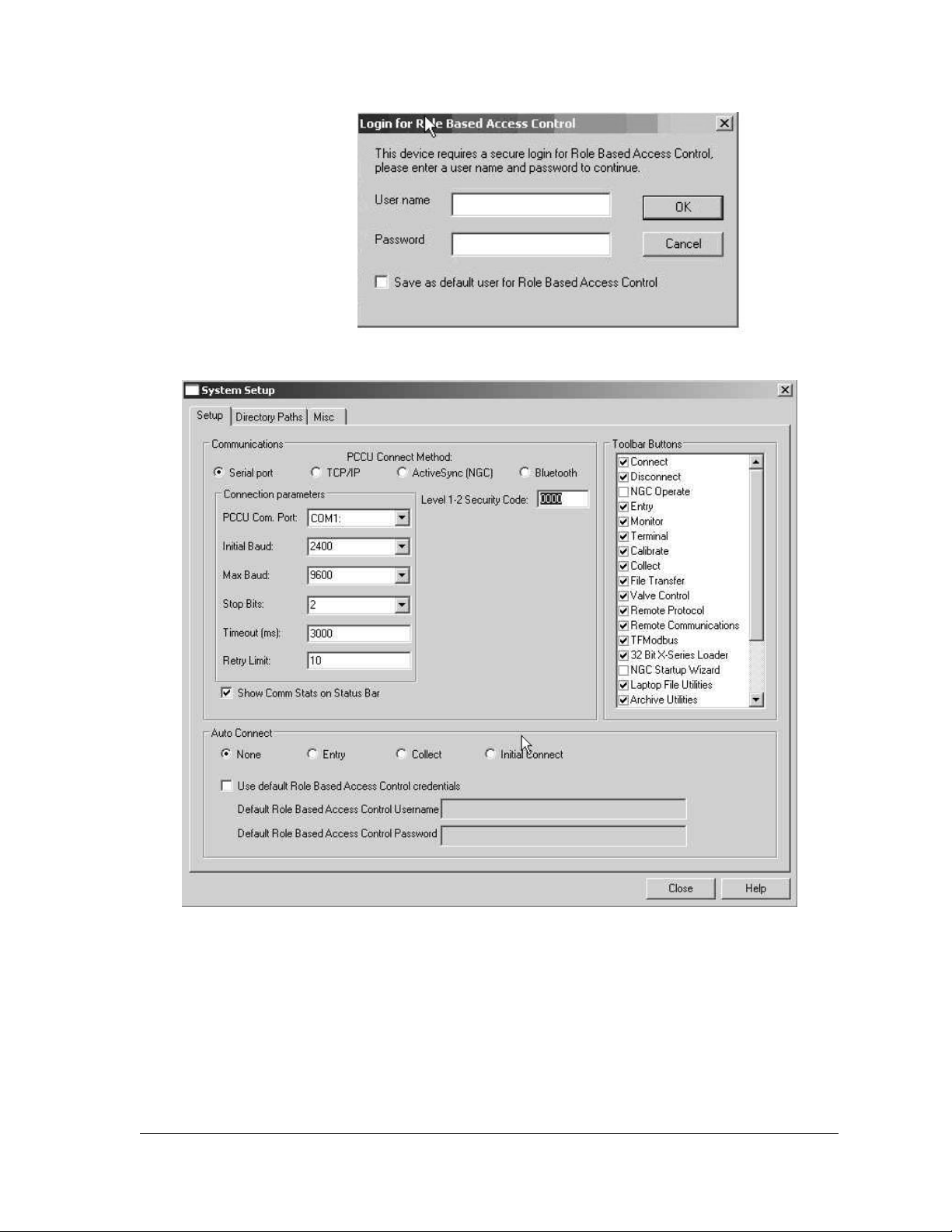
Figure 3–24 Login Dialog Box
Figure 3–25 System Setup Dialog Box
Security Log
To track access to Totalflow G4 devices, a security log is kept that indicates the
date and time when a user logs in, the user name, the port where the access was
made and the actions taken before logout. Log entries are also generated when a
security file is downloaded and/or processed. Additionally, the results of applying
the configurations will also be logged every time a new security file is downloaded.
This tab is available in Advanced and Expert view modes (see Figure 3–26).
2104349-001 – rev. AB Page 3–21
Page 88

Figure 3–26 Security Log Tab
Remote Communications
While it is currently possible to enable RBAC on a remote port, this will block any
access to the port since no host software currently supports RBAC.
Access Rights for Common Functions
Restricted Applications
Applications not accessible to the currently connected user are not seen in the
left-hand tree-view within PCCU32. Functions that are restricted to the user are
disabled. When an application with Read Only functionality is accessed, the Send
button is also grayed out.
Calibration
In order for the user to perform a calibration, in addition to Calibration access
rights, a user must also have read/write access to the following applications:
• System
• Flow measurement
• I/O subsystem
• Display application
For calibrating wireless I/Os, the user must have Read/Write access to the
Wireless I/O application and the Communication Ports application.
For calibrating the XMV, the user must also have Read/Write access to the XMV
Interface application and the Communication Ports application.
Collection
In order to perform a collection, in addition to Collection access rights, a user must
also have Read access to the System application.
For collecting tube data, the user must have Read access to the Flow
Measurement application.
Page 3–22 2104349-001 – rev. AB
Page 89

For collecting trend data, the user must have Read access to the Trend
application.
For collecting analysis trend data, the user must have Read access to the
Analysis Trend application.
For collecting analyzer stream data, the user must have Read access to the
Analyzer Stream application and the Analyzer Operation application.
3.5 Application Licensing Credit Key
3.5.1 Credit Key Driver Installation
3.5.1.1 Step-by-Step Instructions
1) Plug the USB credit key into an available USB port.
2) The Windows operating system will recognize the credit key as new
hardware and attempt to install the appropriate driver with the Found New
Hardware Wizard.
3) Click the Next button.
4) It may be necessary to point the wizard to the PCCU32 directory in the Files
Needed screen. Select Browse, and locate the driver (usbkey.sys) in the
PCCU32 directory.
5) Upon location, click the OK button.
6) The software driver installation will begin. When it is completed, click the
Finish button.
If the user inserts the credit key in a different USB port on
the computer, it will need to be installed for that new USB
port. In other words, the credit key must be installed on
each available port, if the user does not intend to use the
same USB port each time they use the credit key.
3.5.2 Access/View the Credit Key with PCCU32 7.0 (or later)
To access and view the credit key, the user must use PCCU32 7.0 (or later). The
credit key is a secure device and only accessible through PCCU32.
3.5.2.1 Step-by-Step Instructions
1) Install the credit key in an available USB port.
2) Open PCCU32, but do not connect to the unit.
3) Go to the Credit Key License Utility (Operate > File Utilities > Credit Key
License Utility).
To move to the Credit Key License Utility, the user cannot
be connected to the G4 EX. The user must have PCCU32
running and the initial Totalflow PCCU32 screen displayed.
4) When the Credit Key Status and Update Utility screen displays, click Load
to view available credits on the USB key (see Figure 3–27).
2104349-001 – rev. AB Page 3–23
Page 90
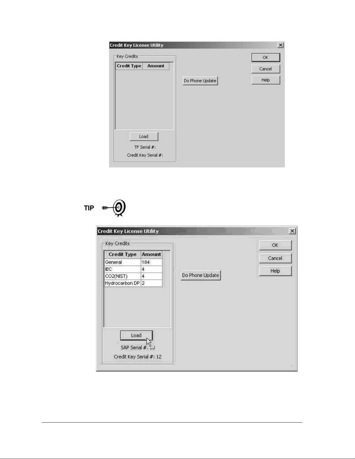
Figure 3–27 Credit Key License Utility
5) The number of credits will display.
This is the same dialog box that the user would use to add more
credits to the credit key.
Figure 3–28 Credit Key License Utility – Status
Page 3–24 2104349-001 – rev. AB
Page 91
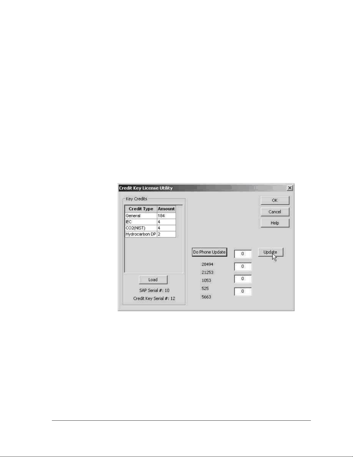
3.5.3 Adding Credits to the Credit Key by Telephone
The user may have ordered the credit key from Totalflow with a specified number
of the various credits; however, the user may need to add more or different credits
in the future.
1) Open PCCU32 version 7.0 or later, but do not connect to the unit.
2) Go to the Credit Key License Utility (Operate > File Utilities > Credit Key
License Utility).
3) Insert the credit key into an available USB port.
4) Select Do Phone Update (see Figure 3–28).
5) The user is then asked to call Totalflow Order Entry. Insure that the credit
key is plugged in.
6) Upon connection with a Totalflow Order Entry representative, click the OK
button.
7) The representative will ask the user to read the five (5) encrypted codes that
appear directly beneath the Do Phone Update button. Read them from top
to bottom (see Figure 3–29).
Figure 3–29 Application Credit Key Entry Screen
8) The representative will give the user four codes to enter in the provided
fields.
9) After the codes have been entered (from top to bottom), click the Update
button (see Figure 3–30).
10) After the button has been clicked, three more codes are displayed directly
beneath the Do Phone Update button. The Totalflow representative will ask
the user to read the codes to verify that the credits have been properly
written to the credit key.
11) When completed, click the Update button.
2104349-001 – rev. AB Page 3–25
Page 92
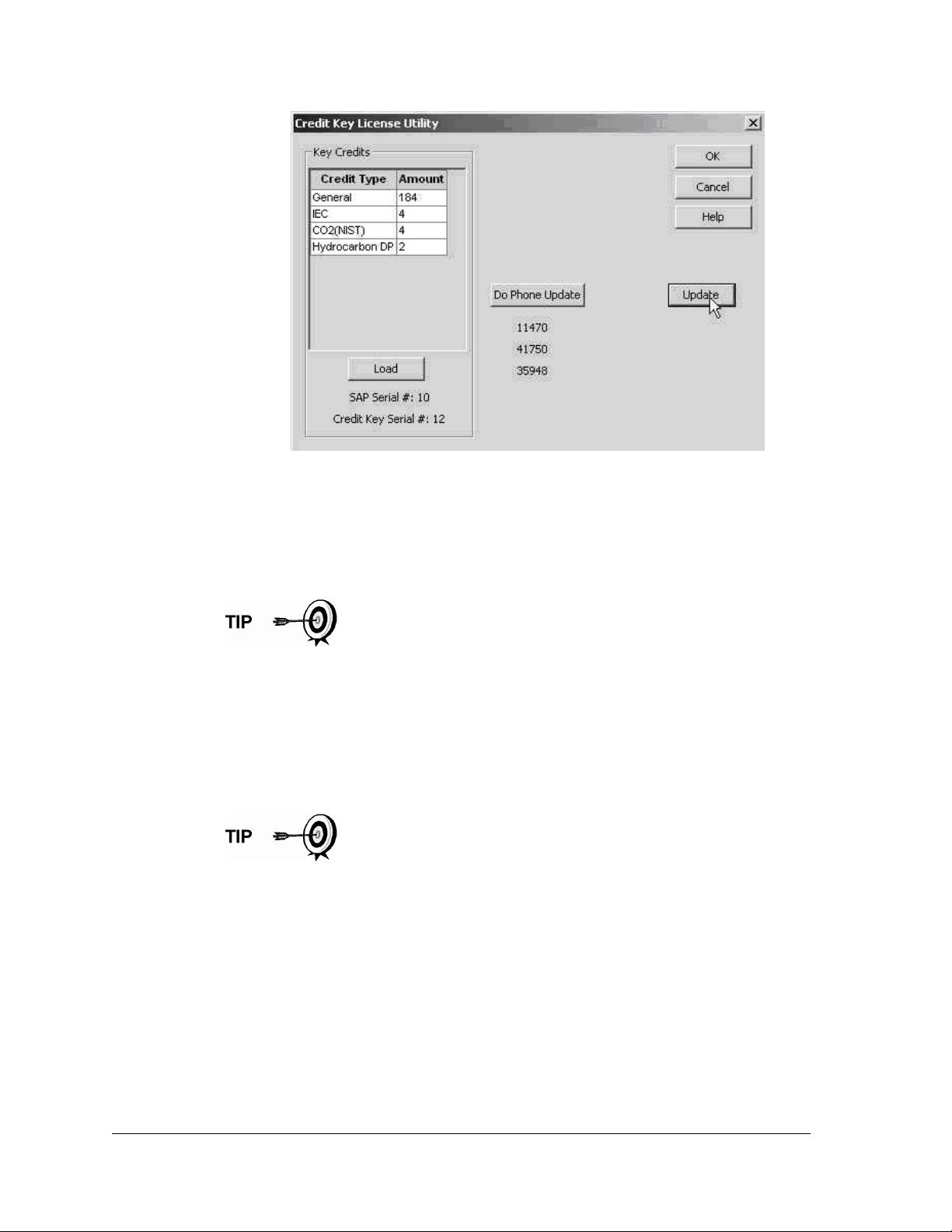
Figure 3–30 Application Credit Verification Codes
3.5.4 Transferring Credits to the G4 EX from the Credit Key
Credits can be transferred to the G4 EX. The user selects the type of credits and
the amount of those credits to be transferred.
If the G4 EX has a surplus of credits, these credits can be
transferred to the credit key to be used on the other meters. This
is discussed in a later section.
To transfer application credits to the G4 EX, the user will need to connect to the
G4 EX with PCCU32 7.0 or later.
1) Open PCCU32. Once open, move to the top of the tree-view, and click on
the App Licensing tab (see Figure 3–31).
2) Install the credit key in an available USB port.
3) Click the Load button to view the available credits.
This screen enables the user to see the licensing status of the
G4 EX as well as the available credits on the credit key. The left
pane shows the type and amount of the available credits on the
credit key. The upper right pane is for information purposes only.
It shows the various available applications and the type/amount
of credits necessary to run the application. The standard credits
(and four general credits) are free with the purchase of the G4
EX. The lower right pane displays the licensing status of the G4
EX. It shows what credits are in the machine, what credits are
being used and any surplus or deficit of credits. A surplus of
credits is highlighted in green. A deficit of credits is highlighted in
red.
Page 3–26 2104349-001 – rev. AB
Page 93
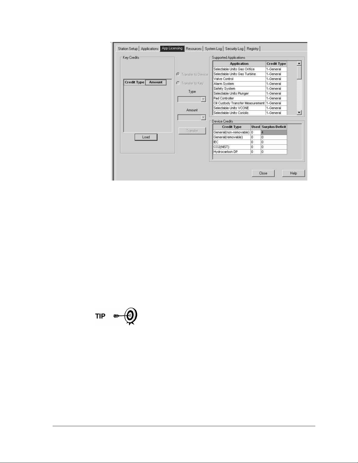
Figure 3–31 App Licensing Tab
4) Select the Transfer to Device radio button.
5) From the Type drop-down menu, select the type of credit from the available
options.
6) Next, select the number of credits to transfer.
7) Upon completion, click the Transfer button.
3.5.5 Transferring Credits to the Credit Key from the G4 EX
As has been mentioned before, excess credits (credits beyond those that are
required to be fully licensed) can be taken from the G4 EX and returned to the
credit key to be used on other G4 devices.
Credits can be transferred from the G4 EX. The user selects the type of credit and
the amount of those credits to be transferred.
If the G4 EX has a surplus of credits, these credits can be
transferred to the credit key to be used on other meters.
If the G4 EX requires additional credits, these credits can be
transferred from the credit key. See the previous section for the
steps on how to accomplish this.
To transfer application credits to the G4 EX, the user needs to connect to the G4
EX unit with PCCU32 7.0 or later.
1) Open PCCU32. Once open, move to the top of the tree-view, and click on
the App Licensing tab.
2) Install the credit key in an available USB port.
3) Click the Load button to view the available credits.
2104349-001 – rev. AB Page 3–27
Page 94
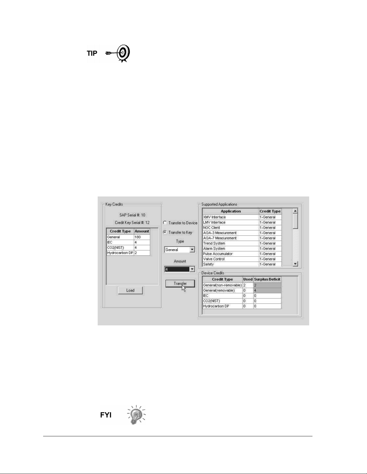
This screen enables the user to see the licensing status of the
G4 EX as well as the available credits on the credit key. The left
pane shows the type and amount of the available credits on the
credit key. The upper right pane is for information purposes only.
It shows the various available applications and the type/amount
of credits necessary to run the application. The standard credits
(and four general credits) are free with the purchase of the G4
EX. The lower right pane displays the licensing status of the G4
EX. It shows what credits are in the machine, what credits are
being used and any surplus or deficit of credits. A surplus of
credits is highlighted in green. A deficit of credits is highlighted in
red.
4) Select the Transfer to Credit Key button (see Figure 3–32).
5) In the Type drop-down field, select the credit type from the available
selections.
6) In the Amount field, set the number of credits to transfer.
7) Upon completion, click the Transfer button.
8) The transferred credits will display to the left of the screen.
Figure 3–32 Transfer to Credit Key
3.6 G4 EX Configuration
3.6.1 Contact Hour
The user can program the G4 EX to begin the contact day based on their contract
or company standards. When the G4 EX first powers up, the contract is preset to
begin at midnight.
Midnight is 00 o’clock. If any value entered is greater than
23, the user will receive an error message, and the G4 EX
forces the value to 00 (midnight).
Page 3–28 2104349-001 – rev. AB
Page 95
3.6.2 Log Period
The Log Period is the specified length of time between writing the calculated
accumulated volume to record. The user may record volumes as often as every
minute and as seldom as every hour. The default is 60 minutes. The G4 EX can
normally store 960 log periods (40 days x 24 logs). A five minute log period will
consume available memory in eight days.
Description Options
Log Period 1,2,5,10,20,30,60 (Minutes)
3.6.3 Volume Calculation Period
Volume Calculation Period is the specified length of time between volume
calculations. The Volume Calculation Period must be equally divisible into the Log
Period. The default is 1 second.
Description Options
1 sec, 2 sec, 5 sec, 10 sec, 20 sec, 30 sec
1 min, 2 min, 5 min, 10 min, 20 min, 30 min and
Volume Calculation Period
60 min.
It is recommended to leave at the default of 1
second.
3.6.4 Calculated Method
When the G4 EX is initially powered up, the calculation method must be set. The
user has the option of setting the calculation method to AGA-3 1985, AGA-3 1992,
AGA-7 or ISO-5167. Once the calculation type has been determined, the user
may toggle specific factors on or off depending upon their availability (see Table
3—1).
Calculation types, and many of the factors involved with setting
up the calculations, are usually dictated by the user’s sales
contract or company policy.
Table 3—1 Configurable Calculation Factors
Calculation Parameter AGA-3 1985 AGA-3 1992 AGA-7 ISO-5167
Fpb (Pressure Base Factor) Yes N/A N/A N/A
Ftb (Temperature Base Factor) Yes N/A N/A N/A
Fg (Specific Gravity Factor) Yes N/A N/A N/A
Fb (Orifice Factor) Yes N/A N/A N/A
Ftf (Flowing Temperature Factor) Yes N/A N/A N/A
Y (Expansion Factor) Yes Yes N/A Yes
Fr (Reynolds Number) Yes N/A N/A N/A
Fa (Orifice Thermal Expansion Factor) Yes N/A N/A N/A
2104349-001 – rev. AB Page 3–29
Page 96
Calculation Parameter AGA-3 1985 AGA-3 1992 AGA-7 ISO-5167
Fpv (Supercompressibility Factor)1
Fw (Water Vapor Factor)4
Faux (Full Well Stream Factor)5
Cd (Coefficient of Discharge) N/A Yes N/A Yes
Fp (Fpv method = NX19 Fixed) Yes Yes Yes Yes
Ft (for Fpv method = NX19 Fixed) Yes Yes Yes Yes
Coefficient of Discharge Calc N/A Yes N/A
Fpc (Pressure Correction Factor) N/A N/A Yes N/A
Ftc (Temperature Correction Factor) N/A N/A Yes N/A
Fs (Fpv2 Compressibility Factor) N/A N/A Yes N/A
Yes Yes
Yes Yes Yes Yes
Yes Yes Yes Yes
Yes2 Yes3
Yes
6
3.6.5 Super Compressibility Calculation (Fpv)
When the G4 EX is powered up, the calculation method needs to be set. The user
has the option of changing the formula method to any one of several other choices
(see Table 3—2). Once the calculation has been determined, the user may toggle
specific parameters on or off depending upon whether they would like to use fixed
or live analysis data.
Many decisions involved with setting up the Fpv are dictated by
the user’s sales contract or company policy.
Table 3—2 Fpv Analysis Data
Analysis Data
Fp (for Fpv method NX19 Fixed) 1.000 Yes No No
Ft (for Fpv method NX19 Fixed) 1.000 Yes No No
Heating Value8
Argon 0.0000 mol % No Yes No
Carbon dioxide CO2 0.0000 mol % Yes Yes Yes
Default
Value
1000.0000 BTU/SCF Yes Yes Yes
Units
NX19 Fixed
Ft/Fp
AGA-8 1992
Detail
All
Others7
1
NX19 GCN, NX19 GCNM, AGA-8 1992 Gross and AGA-8 1992 Detail
2
See Fs for AGA-7 Fpv
3
Only AGA-3 1992 Gross and Detail
4
Not an AGA factor. Fw is a factor which compensates for water vapor in the gas stream and its effect on volume
measurement.
5
Not an AGA factor. Faux is a user set multiplier to compensate for liquids in the gas stream. Defaults to 1.
6
Discharge Coefficient Type-only AGA-3 1992 and ISO-5167-1
7
NX19 GCN, NX19 GCNM, AGA-8 1992 Gross
8
Enter the Heating Value in Btu per SCF. Not used in volume calculations. Only used for calculating MMBTU for reports.
2
Page 3–30 2104349-001 – rev. AB
Page 97
Analysis Data
Carbon monoxide 0.0000 mol % No Yes No
Ethane 0.0000 mol % No Yes No
H2S 0.0000 mol % No Yes No
Helium 0.0000 mol % No Yes No
Hydrogen 0.0000 mol % No Yes No
iButane 0.0000 mol % No Yes No
iPentane 0.0000 mol % No Yes No
Methane 100.000 mol % No Yes Yes
nButane 0.0000 mol % No Yes No
nDecane 0.0000 mol % No Yes No
nHeptane 0.0000 mol % No Yes No
nHexane 0.0000 mol % No Yes No
nitrogen N2 0.0000 mol % Yes Yes Yes
nNonane 0.0000 mol % No Yes No
nOctane 0.0000 mol % No Yes No
Default
Value
Units
NX19 Fixed
Ft/Fp
AGA-8 1992
Detail
All
Others7
nPentane 0.0000 mol % No Yes No
Oxygen 0.0000 mol % No Yes No
Propane 0.0000 mol % No Yes No
Water H2O 0.0000 mol % No Yes No
Specific Gravity 0.6000 N/A Yes Yes Yes
3.6.6 Constants
On a single tube gas orifice meter, there are certain constants or parameters that
may need to be entered or changed from the default values. Table 3—3 displays
the list of these constants.
Table 3—3 Gas Orifice Constants
Parameters
Configurable
Auxiliary Factor (Faux) 1.0 Yes Yes Yes Yes
Barometric Pressure PSIA Yes Yes Yes Yes
DP Zero Cutoff 0.0000 In H2O Yes Yes No Yes
Meter Factor (Fb Basic Orifice
Factor)
Default
Value
210.2300 Yes No No No
Units
AGA-3
1985
AGA-3
1992
AGA-7 ISO-5167
Orifice Coefficient of Expansion 9.2500
In per Deg.
F
No Yes No Yes
2104349-001 – rev. AB Page 3–31
Page 98
Parameters
Orifice Diameter 1.0000 Yes Yes No Yes
Orifice Material Stainless Yes No No No
Pipe Coefficient of Expansion 6.2000
Pipe Diameter 2.0670 Yes Yes No Yes
Pressure Base (Contract) 14.7300 PSIA Yes Yes Yes Yes
Specific Heat Ratio 1.3000 Yes Yes No Yes
Tap Location Upstream Yes Yes No Yes
Tap Type
Temperature Base (Tb) 60.0000 Degrees F Yes Yes Yes Yes
Viscosity 0.0103 Centipoises Yes Yes No Yes
Z of Air at Base Condition 0.9996 No Yes No Yes
Fixed Cd .6 No Yes No Yes
Barometric Pressure 14.73 PSIA Yes Yes Yes Yes
K Factor (Vol. of Gas Per Pulse) 1.0 No No Yes No
Default
Value
Flange
Taps
Units
Inches per
Deg. F
Yes No No Yes
AGA-3
1985
No Yes No Yes
AGA-3
1992
AGA-7 ISO-5167
3.6.7 Alarm Limits
The user has the ability to set the G4 EX alarm limits for the parameters listed in
Table 3—4. There are many purposes for setting these limits, i.e., controlling well
output or sending digital signals.
Table 3—4 Alarm Limits
Parameter Default Value Units
Dp High Limit 2047.9688 In H2O Yes Yes N/A Yes
DP Low Limit 0 In H2O Yes Yes N/A Yes
Flow Rate High Limit 1,000,000 SCF/Hr Yes Yes Yes Yes
Flow Rate Low Limit 0 SCF/Hr Yes Yes Yes Yes
RTD High Limit 420 Degrees F Yes Yes Yes Yes
RTD Low Limit 0 Degrees F Yes Yes Yes Yes
SP High Limit 2047.9688 PSIA Yes Yes Yes Yes
Uncorrected Vol High
Limit
Uncorrected Vol Low
Limit
ACF N/A Yes Yes Yes
ACF N/A Yes Yes Yes
AGA-3
1985
AGA-3
1992
Configurable
AGA-7 ISO-5167
Page 3–32 2104349-001 – rev. AB
Page 99
3.6.8 Reset Volume
When the user resets the volume accumulator, the G4 EX will:
• Store time, date and previous accumulated partial calc period volumes into
the historical record file.
• Zero the remaining partial calc period accumulations.
• Complete all computations for the present flow file daily records.
• Begin a new flow file daily record.
• Zero total volume accumulator, and log the event with an accumulator value
before zeroing out the accumulator.
Since the G4 EX volume calculations are made each vol
calc period, any changes that are made during the period
would effect the volume calculations (such as changing the
orifice plate size) and be introduced into the calculations.
To avoid introduced errors, it is recommended that the
Reset Volume command be used. This command forces
the G4 EX to perform volume calculations for the elapsed
time since a previous volume calculation was made. A new
partial period volume is added to the volume accumulator.
This is logged as an event before it is reset to zero (0).
3.7 Start Up the G4 EX
3.7.1 Putting the G4 EX On Line
3.7.1.1 Step-by-Step Instructions
1) Open both the bypass valves, and close the vent to the atmosphere valve.
This stabilizes the pressure on both sides of the cell.
2) Begin to slowly open the high side orifice tap valve from the meter run.
3) Begin to slowly open the low side valve.
4) Once both the high and low sides are completely open, close both bypass
valves.
3.7.2 Setting G4 EX Temperature Calculation
The G4 EX temperature calculations can be set to the following conditions:
• RTD Installed – This uses the RTD temperature input and stores the RTD
temperature unless the RTD fails. Additionally, it then uses and logs the
Fixed GF value.
• Use Fixed TF – This uses and stores the fixed temperature.
To avoid a calibration shift, carefully follow these
instructions.
2104349-001 – rev. AB Page 3–33
Page 100

3.8 G4 EX Standard Displays
3.8.1 Program Display
The single tube G4 EX comes from the factory with a set of default displays (see
Table 3—5). By default, each display item remains on the display for five seconds.
The user has the ability to change this default to zero (item not displayed) or any
value from 1 to 255 seconds. The user is also able to change the engineering
units and data format for display purposes. Further instructions on programming
the display system can be found in the PCCU32 help files. All display items and
item groups are user programmable and may be displayed by user defined
parameters.
Table 3—5 G4 EX Displayed Items
Description Format Note
DATE/TIME
YEST DP LO NN PERCENT
YEST DP HI NN PERCENT
FLOWRATE NNNNNN.N SCF/HR
ACCUM VOL NNNNNN.NN MCF
BATTERY NN.N VOLTS Battery voltage volts
DIFF PRESS NNN.N IN. H2O Differential pressure inches H2O
STATIC PRESSURE NNN.N PSIA Static pressure static PSIA
FLOW TEMP NN.N DEG. F Flowing temperature °F
YEST VOL NNNN.N MCF
PERIOD VOL NNNN.N SCF
MM/DD/YY
24-hour clock
HH:MM:SS
Yesterday’s percent DP low limit percent time
below DP low setpoint
Yesterday’s percent DP high limit percent time
below DP high set point
Current flow rate programmable SCF or MCF or
MMCF
Total accumulated volume programmable SCF
or MCF or MMCF
Yesterday’s volume programmable SCF, MCF
or MMCF
Previous period volume last volume calculation
period volume
Orifice Diameter N.NNNN INCHES Diameter of installed orifice
STATION ID XXXXXXXXXX 10 character alphanumeric identifier
DEVICE ID XXXXXXXXXX
10 character alphanumeric application or tube
identifier
Page 3–34 2104349-001 – rev. AB
 Loading...