

Page 1
Toll: +1 (800) 348-4753
Tele: +1 (260) 484-0382
Fax: +1 (260) 484-9230
[email protected]
www.tcsmeters.com
ENGINEERING MANUAL
700 SERIES ROTARY FLOW METER
© Total Control Systems 2007
Fort Wayne, Indiana U. S. A.
Page 2

Page No.
Table of Contents
1
Quote and Purchase Specifications
2
Rotary Design
3
Meter Type Classification
4
Meter Selection Factors
Metrology
5
Accuracy
6
Material Compatibility
6
Flow Rate
6
Pressure
6
Temperature
7
Lubricity
7
Suspension and Suspended Solids
7
Foreign Materials
8
PH
8
Viscosity
8
Pressure Loss
9
Bearing Load
10
System Design
Plumbing Figuration
10
Slow Flooding of System
11
Protection From Debris
11
Calibration
11
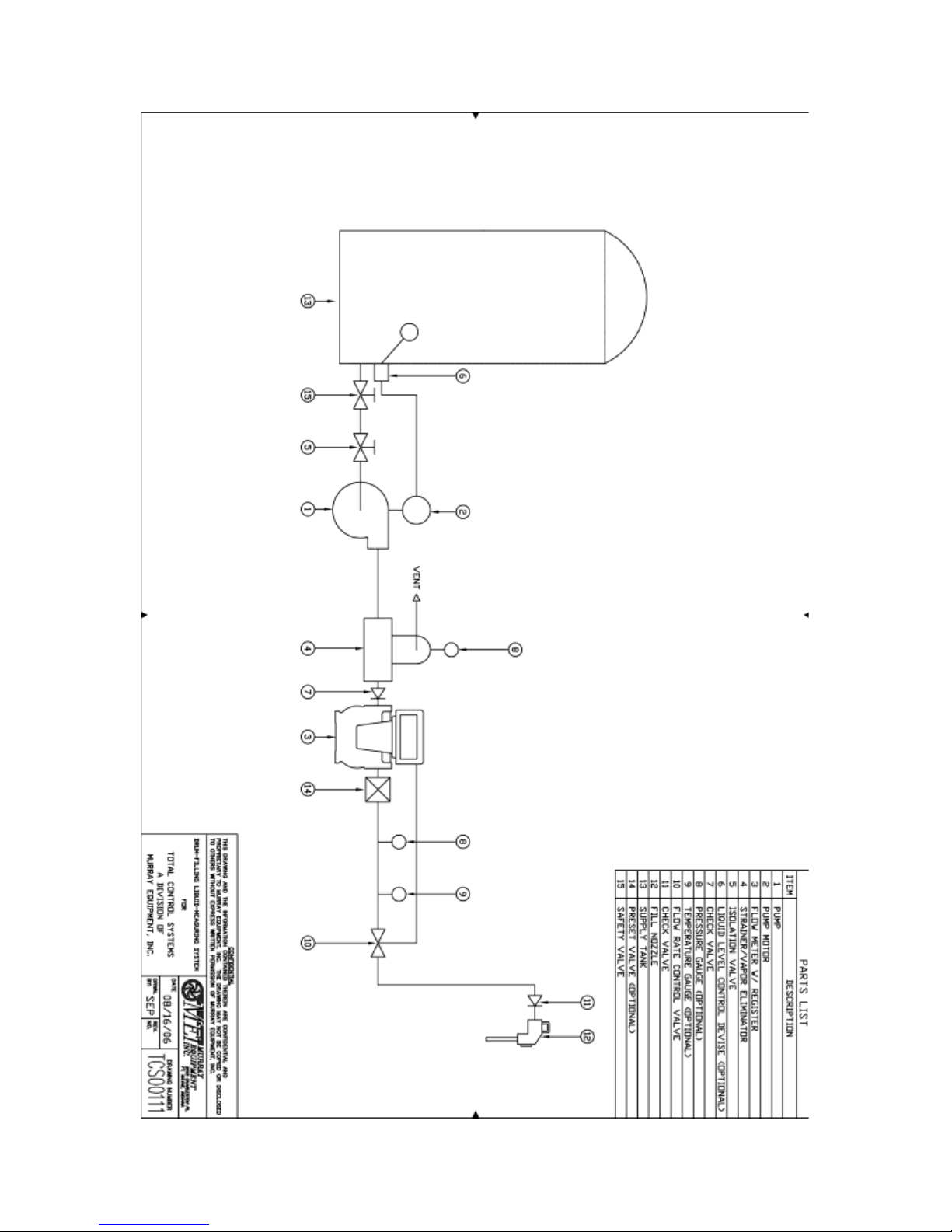
Drum Filling System
12
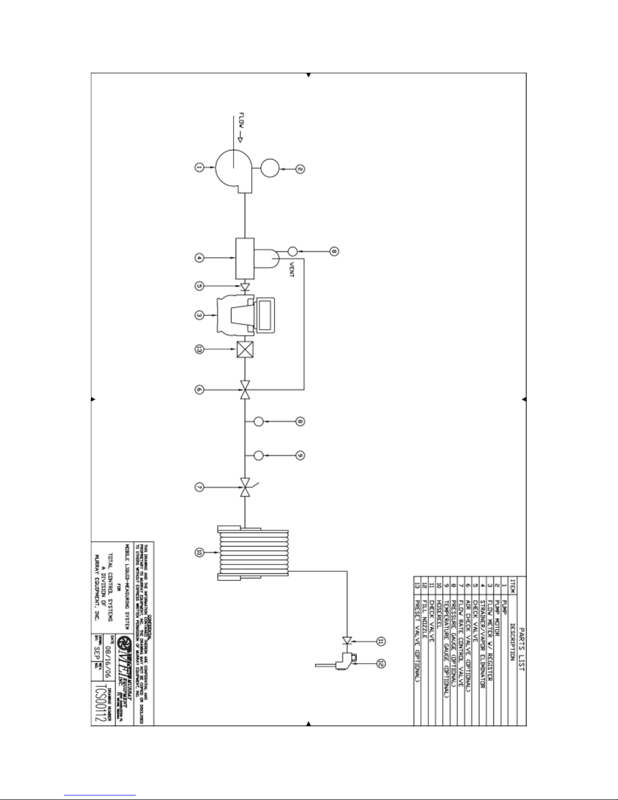
Mobile Fueling System
13
Hydraulic Shock
14
Thermal Expansion
14
Thermal Shock
14
Products that Dry/Congeal/Crystallize
14
LPG
14
Meter Calibration
16 - 18
Product Depletion (Split Compartment)
18 - 20
Calibration Procedure
21
Direction of Flow
22
700 Series Materials of Construction
23
Chemical Compatibility
23 - 35
Metric Conversion Guide
36
Registration Specifications
Gear Plate Information
37
Pulse Output
38
Approximate Weights
39
Glossary
40 - 42
Material Safety Data Sheet (MSDS) for Calibration Fluid
43 - 46
TABLE OF CONTENTS
- 1 -
Page 3

QUOTE & PURCHASE SPECIFICATIONS
When issuing quote and purchase specifications and to assure you of receiving a Total Control
Systems meter with all of the many performance, installation, operating, and maintenance
advantages available only with a TCS meter. We suggest that 700 series meter-engineering
specifications include the following statements in addition to a TCS model number and
description.
“Meter shall be of a flow meter with a positive displacement design having rotary motion
without axial thrust or flow disruption. No eccentric, sliding, reciprocating or oscillating parts to
induce excess liquid shear or liquid compressibility within meter element. Meter shall have three
rotors that rotate in unison within the measuring chamber. Rotary parts to be horizontally
supported on both sides by solid support bearings and rotor journals of materials compatible with
product to be metered. Meter shall have stainless steel timing gears with no ball bearings, springs,
or cams. Rotary drive and meter adjustment output to all mechanical readout shall be capable of
infinite meter accuracy adjustment of 0.02% or better. Meter calibration adjustment device must
be externally accessible not requiring removal of any readout equipment for calibration or
replacement. Meter shall immediately respond to product low flow movement.”
NOTICE
Total Control Systems (TCS) shall not be liable for technical or editorial errors in this manual or
omissions from this manual. TCS makes no warranties, express or implied, including the
implied warranties of merchantability and fitness for a particular purpose with respect to this
manual and, in no event, shall TCS be liable for special or consequential damages including, but
not limited to, loss of production, loss of profits, etc.
The contents of this publication are presented for informational purposes only, and while every
effort has been made to ensure their accuracy, they are not to be construed as warranties or
guarantees, expressed or implied, regarding the products or services described herein or their use
or applicability. We reserve the right to modify or improve the designs or specifications of such
products at any time.
TCS does not assume responsibility for the selection, use or maintenance of any product.
Responsibility for proper selection, use and maintenance of any TCS product remains solely with
the purchaser and end-user.
All rights reserved. No part of this work may be reproduced or copied in any form or by any
means – graphic, electronic or mechanical – without first receiving the written permission of
Total Control Systems, Fort Wayne, Indiana USA.
- 2 -
Page 4
DESIGN
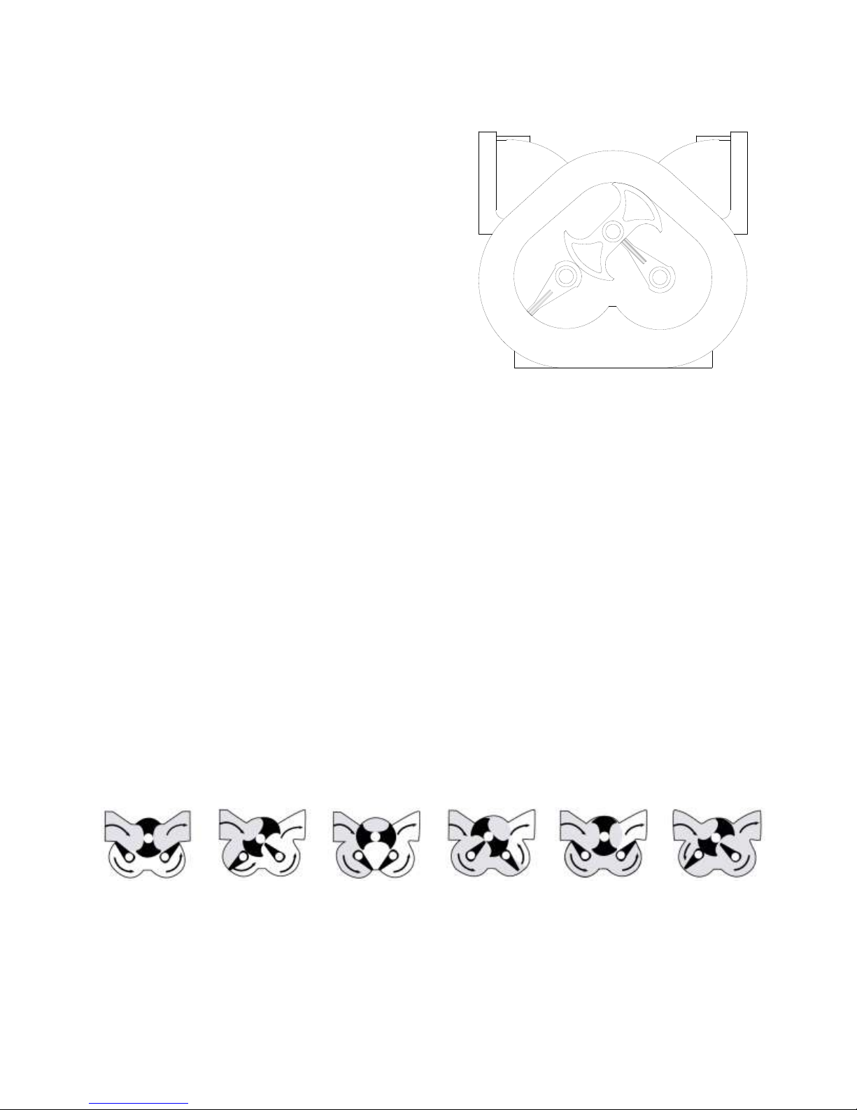
The TCS Model 700 series flow meter is a simple
and efficient design. The meter consists of a single
fluid chamber that contains a single blocking rotor
and two displacement rotors whose rotation is
synchronized with mating gears. As the fluid
enters the fluid chamber, the blocking rotor is
forced to rotate. The displacement rotors, also
rotating in conjunction with the blocking rotor help
direct the fluid flow through the chamber and to the
outlet. The linear flow of the fluid is thus
translated into rotary motion in the meter. The
output of the meter is picked up from the rotation
of the blocking rotor and transmitted to a register or
pulse transmitter.
The rotors in the meter are designed to operate at close tolerances to one another and the wall of
the fluid chamber. There are slight gaps between the rotors and the chamber wall. Because of
this, it is important that the meter be properly applied for the flow rate and operating pressure of
the system.
Because the fluid flowing through the meter is redirected only slightly from its natural flow,
there is very little pressure drop across the meter, unlike other meters that use multiple measuring
chambers.
The meter design uses high quality long life materials for the rotor bearings and journals. Since
there is no contact between the rotors and the fluid chamber wall, these critical components have
a long life expectancy.
Calibration of the meter involves adjusting the rotation of the output shaft relative to the rotation
of the internal rotors of the meter. This is accomplished by changing the settings on an adjuster
device. Calibration of the meter is discussed in detail in the section Meter Calibration.
700 METER FLOW ILLUSTRATION
- 3 -
Page 5

METER TYPES
SP STANDARD PETROLEUM
For metering refined petroleum products such as Leaded and Unleaded Gasoline, Fuel Oils,
Diesel, Bio-Diesel, Kerosene, Vegetable Oils, Motor Oils, Ethylene Glycol (Antifreeze), etc.
SPA STANDARD PETROLEUM (AVIATION)
For metering refined petroleum products such as Aviation Gasoline, Jet Fuels, Gasoline, Fuel
Oils, Diesel, Bio-Diesel, Kerosene, Motor Oils, etc.
SPD STANDARD PETROLEUM (DUCTILE IRON)
For metering alternative fuels such as Natural Gasoline, Ethanol, Methanol, Bio-Diesel, Aviation
Gasoline, Fuel Oils, Diesel, Motor Oils, etc.
LP LIQUEFIED PETROLEUM
For metering Liquefied Petroleum Gas (LPG).
IP INDUSTRIAL PRODUCTS
For metering Food Products, Industrial Products, General Solvents and many other liquids; such
as Liquid Sugars, Corn Syrup, Soy Bean Oil, Shortenings, Latex Products, Adhesives, etc.
IC INDUSTRIAL PRODUCTS WITH CARBON BEARINGS
For metering Industrial Chemicals, General Solvents, Water and other Non-lubricating Liquids,
such as Alcohol, Acetones, Ethanol, Naphtha, Xylene, MEK, Toluene, Deionized Water,
Demineralized Water, Potable Water, etc.
AF ALL FERROUS
For metering Pesticides, Nitrogen Solutions, Fertilizer, Chlorinated Solvents, Paints, Inks,
Alcohols, Adhesives, Motor Oils, Molasses, Corn Syrup, Liquid Sugars, etc.
SS STAINLESS STEEL
For metering the same liquids as the SP, SPA, SPD, IP, IC and AF flow meters, but includes
food processing and special handling fluids such as Nitric, Phosphorus and Glacial Acetic Acids,
Anti-Icing Fluids, Vinegar, Fruit Juices, etc.
- 4 -
Page 6

Meter
Type
Available
Flange
Connection*
Maximum
Capacity
Working
Pressure
Working
Temperature**
700-15
SP, SPA,
IP & IC
1½”NPT Flange;
2” optional
60 GPM
(227 LPM)
150 PSI
(10.5 BAR)
-40°F to 160°F
(-40°C to 71°C)
700-20
SP, SPA,
SPD, IP, IC,
AF & SS
2” NPT Flange;
1½”optional
100 GPM
(380 LPM)
150 PSI
(10.5 BAR)
-40°F to 160°F
(-40°C to 71°C)
700-20
LP
2” NPT Flange;
1½”optional
100 GPM
(380 LPM)
350 PSI
(24.1 BAR)
-30°F to 140°F
(-30°C to 60°C)
700-25
SPA, SPD
2” NPT Flange
150 GPM
(567 LPM)
150 PSI
(10.5 BAR)
-40°F to 160°F
(-40°C to 71°C)
700-30
SP, SPA,
SPD, IP, IC
& AF
3” NPT Flange
2”optional
200 GPM
(760 LPM)
150 PSI
(10.5 BAR)
-40°F to 160°F
(-40°C to 71°C)
700-35
SPA, SPD
3” NPT Flange
300 GPM
(1135 LPM)
150 PSI
(10.5 BAR)
-40°F to 160°F
(-40°C to 71°C)
700-40
SP, SPA,
SPD, IP, IC
& AF
4” NPT Flange;
3” optional
500 GPM
(1893 LPM)
150 PSI
(10.5 BAR)
-40°F to 160°F
(-40°C to 71°C)
700-45
SPA, SPD
4” NPT Flange
600 GPM
(2271 LPM)
150 PSI
(10.5 BAR)
-40°F to 160°F
(-40°C to 71°C)
METER OPERATING SPECIFICATIONS
* Flanged NPT is Standard; BSPT, Slip Weld, ANSI and others are available upon request.
** Higher working temperatures can be achieved at reduced pressures (consult factory for more information)
METER SELECTION FACTORS
WEIGHTS&MEASURES
Before any meter can be specified, knowledge of each application is required. If the liquid is to
be sold through a metered delivery, domestic or international certification from a governing body
may be required. Total Control Systems strictly adheres to all domestic and international
metrology conformance regulations for the custody transfer of fluids. For questions regarding
weights and measures approvals or other issues, please consult factory.
- 5 -
Page 7

TYPICAL ACCURACY CURVE
-0.4
-0.2
0
0.2
0.4
0 10 20 30 40 50 60 70 80 90 100
PERCENT OF FLOW RATE
% DEVIATION
Gasoline
Fuel Oil
The 700-meter’s accuracy (percent of error over or under the zero – error level) remains within
design parameters (+/- 0.15%) over its minimum rated flow range to its maximum rated flow
range for custody transfer meter requirements. This percentage meets or exceeds the Wholesale
and Vehicle accuracy requirements for accurate custody transfer of product, as specified in the
National Institute of Standards and Technology (NIST) Handbook 44.
PRODUCT CHARACTERISTICS
A) Material Compatibility
The product intended to be measured must review Total Control Systems CHEMICAL
COMPATIBILITY on page 23 to 35 to find the suitable materials and meter type. Materials
incompatible with product will potentially reduce accuracy, operation life, contaminate liquid
and may be harmful to others.
B). Flow Rate
The minimum and maximum system rate of flow must be determined for the selection of
flow meter. The flow rate of the system is dependent upon the product viscosity; the desired
meter configuration, the systems pump capabilities, and the plumbing configuration.
C) Pressure
The maximum working pressure allowed should be reviewed under flow meter type and
pressure rating. All meters meet the European Pressure Equipment Directive (PED) No.
97/23/EC. Failure to adhere to the maximum allowable pressure may potentially cause a seal
leak or casting rupture.
-6 -
Page 8

Meter Type
SP/SPA/SPD/IP/IC/AF/SS
LP
150F/150PSI
150F/350PSI
200F/100PSI
200F/275PSI
250F/75PSI
250F/250PSI
300F/50PSI
300F/150PSI
D) Temperature
The operating temperature has a great effect on the meter seals and its relationship to the
maximum pressure allowed with the flow meter castings. It will be necessary to reduce the
maximum rated working pressure as the operating temperature increases. Any metering
system operating over 160F (71C) will require extra clearance rotors to compensate for
material expansion. Any metering system operating over 180F (82 C) will require at least a
one (1) foot registration extension to protect the registration devices. Increase in temperature
may increase the corrosion rate of some products.
1) O-ring / Packing Seal Temperature Rating
UL Buna -20F to 140F -30C to 60C
UL Viton -104F to 221F -75C to 105C
Viton -31F to 400F -35C to 204C
Simriz -40F to 450F -10C to 230C
Teflon -20F to 500F -30C to 260C
The Acetyl Face Gear and Bushings, in the register support assembly;
maximum temperature is 180F (82C)
2) Pressure rating at elevated temperatures.
E) Lubricity
The lubricity or non-lubricity of the product will determine the bearing sleeve material
suitable for use. Products with no lubrication will require the use of Carbon Graphite or
Ceramic bearing sleeves. Products with lubrication will reduce friction between two metal
surfaces and help dissipate heat.
F) Suspensions & Suspended Solids
Products with a low percentage of soft suspensions or suspended solids will require clearance
rotors and/or Ceramic bearing sleeves to protect the meter from its abrasive effects. High
percentages (5%) of suspensions or suspended solids, or any hard solids, such as sand, are
not recommended for the 700 series meter. Due to the very tight machining tolerances any
solid, larger than the thickness of a piece of paper, has the potential of stopping the flow
through the meter and can cause damage to the meter.
- 7 -
Page 9
pH SCALE
NEUTRAL
0 1 2 3 4 5 6 8 9
10
11
12
13
14
◄——— ACID REACTION ———
——— ALKALINE REACTION ——►
7
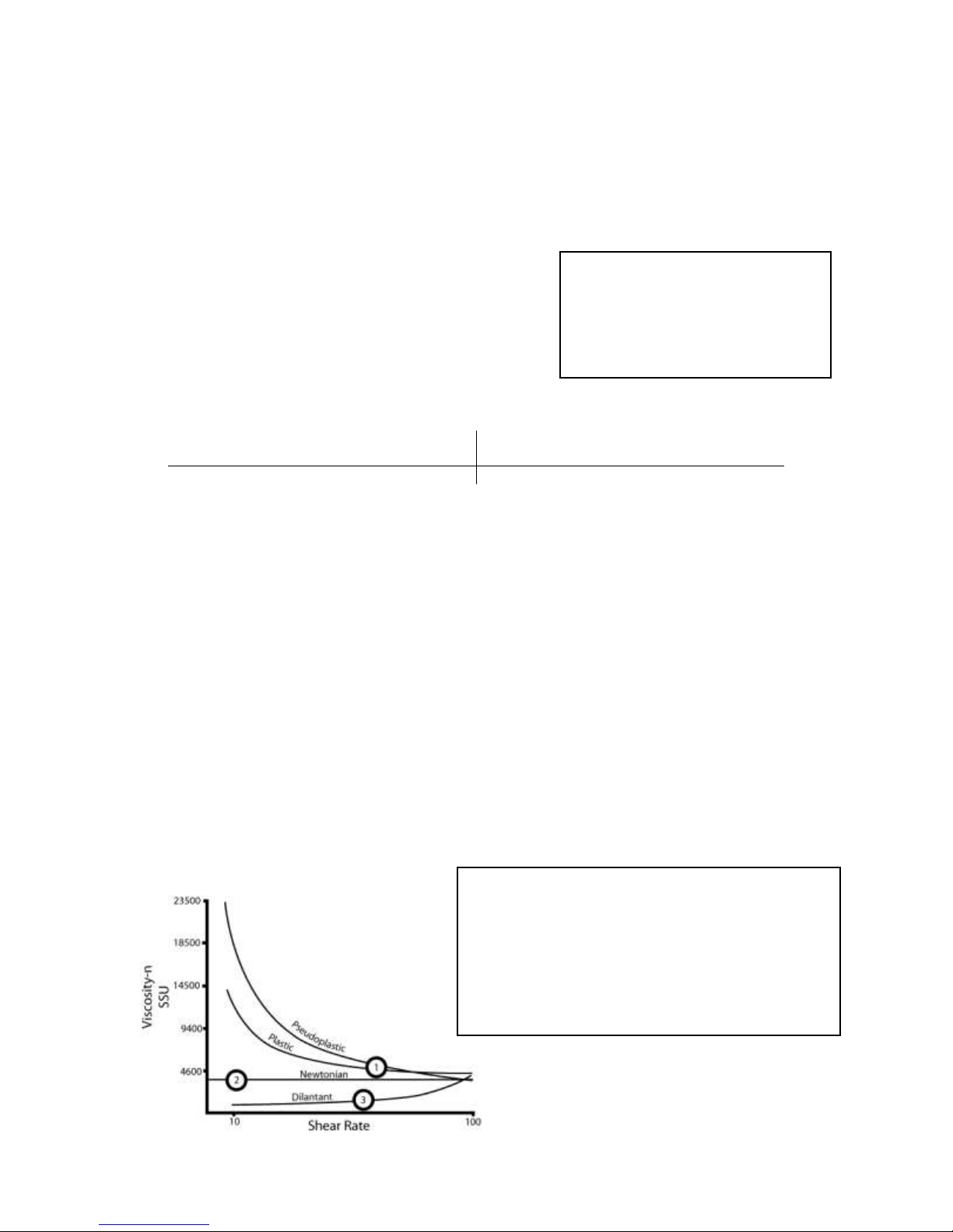
1) Thixotropic Liquids (Plastic and Peudoplastic)
Viscosity decreases as shear rate increases. Typical liquids include
Gels, Latex paints, lotions, Shortening, Mayonnaise, Printers Ink, Hand
cleaner and Yeast.
2) Newtonian Liquids – Viscosity remains unchanged with shear.
3) Dilatants Liquids – Viscosity increases as shear rate increases. Most
liquids in this category are unsuitable with PD flow meters; these
include Clay, Slurries and some confectionary bases.
Material pH
Aluminum 5 – 8
Ductile Iron 5.5 – 11
Ni-Resist 5.5 – 14
Stainless Steel 0 – 14
G) Foreign Materials
Products that are to be measured may have foreign materials present. The inlet side of any
positive displacement meter should be equipped with a strainer. Matching the strainer size or
one size larger, with an appropriate size screen will protect the meter and accessories from
damage in the system. A minimum of 40-mesh screen is recommended for petroleum service.
H) pH
The metal resistance to the effects of high or low
PH is difficult to calculate because of the varying
concentrations and corrosiveness of properties.
This is a generalized rating for pH resistance.
I) Viscosity
Viscosity is the property of a fluid that is a measure of its resistance to flow. Among the
earliest to express this quantitatively was Sir Isaac Newton. He reasoned that the viscosity of
a liquid was proportional to its shear stress (or resistance to shear). Liquids that behave in
this manner are referred to as “Newtonian” liquids and are typically by petroleum fluids,
water and similar chemicals.
Other types of fluids are grouped into a general category called “Non-Newtonian” which
includes dilatants, plastic, pseudoplastic and thixotropic. Liquids in this group are
characterized by viscosity that changes with the rate of shear as compared to the NonNewtonian fluids where viscosity is basically constant with shear and flow rate. As a
consequence, Newtonian fluids are much easier to predict with regard to their performance
through a flow meter than are the Non-Newtonian liquids.
Many of the more viscous liquids pumped through the 700 series rotary flow meter are
plastic and pseudoplastic and as such are reduced in effective viscosity after being presheared by the pump. The diagram below shows how viscosity varies as a function of shear
rate on various types of liquids.
- 8 -
Page 10

PRESSURE DROP CURVE
32 SSU SOLVENT
0
0.5
1
1.5
2
2.5
3
0 10 20 30 40 50 60 70 80 90 100
PERCENT OF FLOW RATE
P.S.I.
SSU SSU SSU SSU
CPS
Saybolt
CPS
Saybolt
CPS
Saybolt
CPS
Saybolt
Centipoise
Universal
Centipoise
Universal
Centipoise
Universal
Centipoise
Universal 1 31
200
1,000
900
4,300
7,000
32,500 2 34
220
1,100
1,000
4,600
8,000
37,000
4
38
240
1,200
1,200
5,620
8,500
39,500
7
47
260
1,280
1,300
6,100
9,000
41,080
10
60
280
1,380
1,400
6,480
9,500
43,000
15
80
300
1,475
1,500
7,000
10,000
46,500
20
100
320
1,530
1,700
8,000
15,000
69,400
25
130
340
1,630
1,800
8,500
20,000
92,500
30
160
360
1,730
1,900
9,000
30,000
138,500
40
210
380
1,850
2,000
9,400
40,000
185,000
50
260
400
1,950
2,200
10,300
50,000
231,000
60
320
420
2,050
2,400
11,200
60,000
277,500
70
370
440
2,160
2,500
11,600
70,000
323,500
80
430
460
2,270
3,000
14,500
80,000
370,000
90
480
480
2,380
3,500
16,500
90,000
415,500
100
530
500
2,480
4,000
18,500
100,000
462,000
120
580
550
2,660
5,000
23,500
125,000
578,000
140
690
600
2,900
5,500
26,000
150,000
694,000
160
790
700
3,380
6,000
28,000
175,000
810,000
180
900
800
3,880
6,500
30,000
200,000
925,000
Centistokes
=
Centipoise
Centipoise
=
Centistokes x Specific Gravity
Specific Gravity
CONVERSION FACTOR
SSU
Multiplier
30 = 1.0
100 = 1.5
500 = 2.5
1000 = 3.2
2000 = 4.0
3000 = 4.7
4000 = 5.0
5000 = 5.5
7500 = 6.5
10000 = 7.0
25000 = 10.0
50000 = 13.5
J) Pressure Loss
The pressure drop is the difference between of the inlet and outlet pressure of the flow meter
while operating. When measuring a liquid, the pressure drop will increase as the flow rate
increases. When the metering system has accessories such as an air eliminator or valve,
these items will be approximately the same pressure drop through equivalent size meter.
EXAMPLE:
A 700-20SP flow meter, air eliminator, strainer and preset valve. Operating at 80 GPM on a
2000 SSU lubricating oil.
Flow Meter: 1.5 PSI x 4.0 = 6 PSI Pressure Loss
Air Eliminator/Strainer: 1.5 PSI x 4.0 = 6 PSI Pressure Loss
Preset Valve: 1.5 PSI x 4.0 = 6 PSI Pressure Loss
Total Pressure Loss is 18 PSI
VISCOSITY CONVERSION
(Specific Gravity = 1)
- 9 -
Page 11
K) Bearing Load
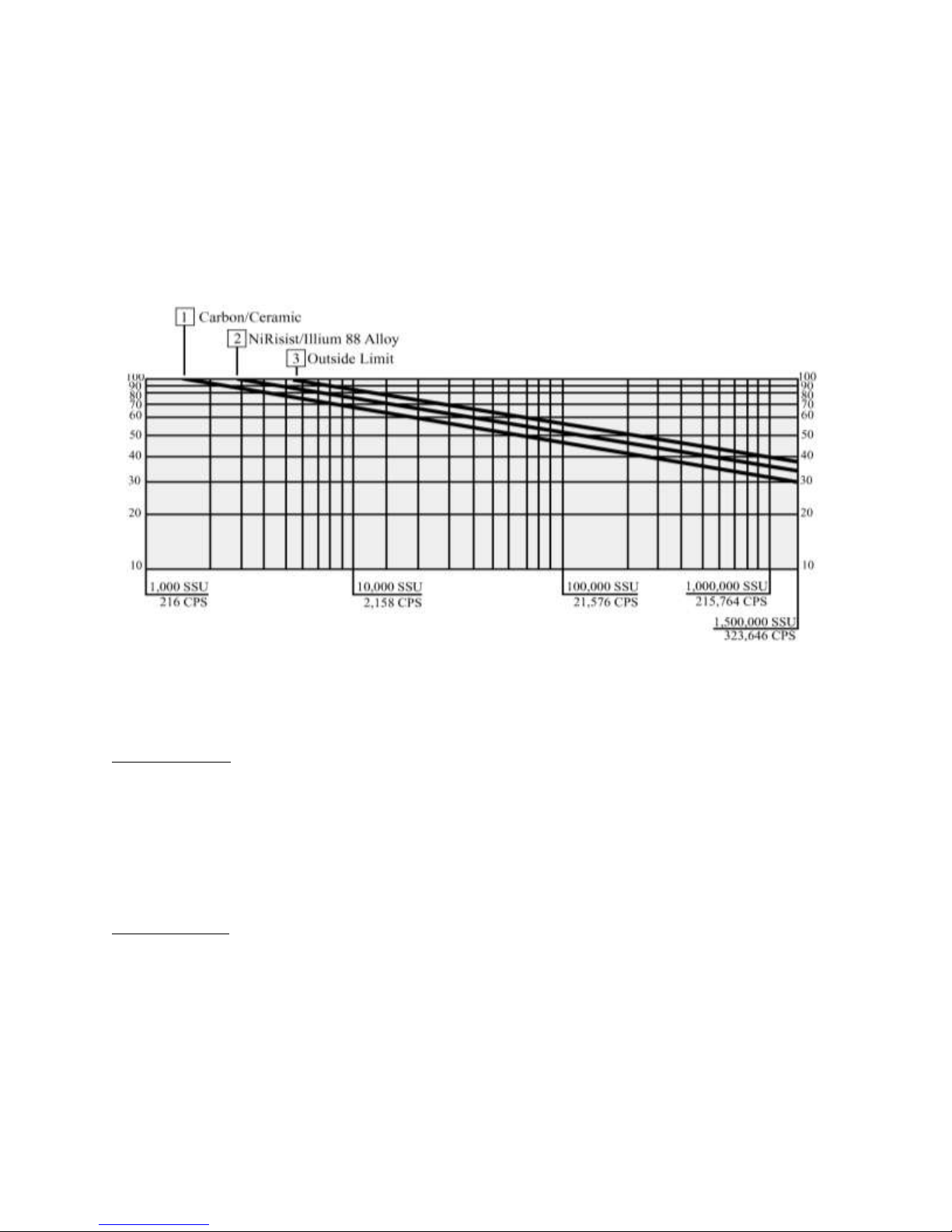
The product viscosity will have a direct relationship on the flow rate of the system. The
following chart is a flow meter selection guide based on the relationship of viscosity and
flow rate. The bearing material is illustrated according to maximum bearing load allowable.
In the following flow chart, please choose the system flow rate and the product viscosity.
Then select the proper bearing sleeve material to identify the flow limitations of the flow
meter. If the system flow rate and viscosity do not meet your requirements, choose the next
size of flow meter or reduce the flow rate.
SYSTEM DESIGN
Meter Selection
The flow meter must be carefully chosen from the Meter Selection factors in the Engineering
Manual. The meter must be selected based on the operating system and product characteristics.
System variables include flow rate, temperature and pressure. The product characteristics
include the material compatibility, lubricity, viscosity, suspensions, pH, and whether the product
can congeal, crystallize or leave a dry film. Failure to select the correct flow meter may result in
system failure or serious injury.
Air Elimination
In any system that the tank may be completely drained or multiple products manifold into one
metering system, the possibility of air being present increases. The solution is an air or vapor
eliminator located before the flow meter to vent the air or vapor from the system before it can be
measured. Air or vapor elimination is required for all weights and measures regulatory
approvals in custody transfer applications.
- 10 -
Page 12

Control Valves
Safety and isolation valves should be used throughout the metering system. In any pumping
system where there is one (1) pump and multiple flow meters, a digital or hydro-mechanical
Rate-of-Flow control valve must be used at each flow meter to prevent over speeding of the flow
meters.
Best Plumbing Configuration
1). Flow meter must have secure mounting to a riser stand or the foundation.
2). The inlet and outlet piping must be securely supported, in a manner of not to allow pipe
stress on flow meter.
3). System should be designed to keep the flow meter full of liquid at all times.
4). System piping should have the same full pipe diameter or larger as the flow meter,
throughout the metering system to allow for minimal pressure loss.
5). The pipe should be laid out as straight as possible to reduce pressure loss from flow
restriction.
6). The meter and piping must be installed in such as way as to avoid accidental draining of the
meter. Meter inlet and outlet should be lower than the associated system plumbing (sump
position).
7). It is not necessary for the air eliminator to be installed bolted directly to the meter. It can be
installed upstream from the meter. For effective operation of the air eliminator, it should be
mounted between the meter and any valves, tees or any other potential places where air may
enter the system.
8). The metering system should include a means for calibration.
Protection From Debris
On new installations, care must be taken to protect the meter from damage during start-up. It is
recommended to put a strainer before the meter. Damage may result from the passage through
the meter of dirt, sand, welding slag or spatter, thread cuttings, rust, etc. The insertion of a spool
(a flanged length of pipe equal in length to the meter and accessories attached to the meter) in
place of the meter until the system is flushed, temporarily bypassing the plumbing around the
meter, will also protect the meter from debris. Once the system has run “clean” for a period of
time the meter may be reinstalled or protective devices removed.
Thermal Expansion
As with most liquids, they will expand and contract with temperature. In any system where there
is a chance for liquid to be captured between closed valves without relief, thermal expansion will
likely occur and create dangerously high pressures within the system. Care should be taken in
designing the system in which thermal shock may occur by implementing Pressure Relief Valves
or Thermal Expansion Joints in the system design.
When product is trapped within the system, the pressure will increase by 126 PSI (8.69 BAR) for
every one (1) temperature degree increase.
- 11 -
Page 13

Thermal Shock
The system operating temperature will expand or contract the metals within the flow meter. For systems
that have sudden or immediate temperature increases of 68 F (20 C) degrees or more, will require
clearance rotors. Clearance rotors will be necessary to eliminate the effect of immediate
expansion of the rotors vs. meter body, caused by thermal shock.
Hydraulic Shock (Water Hammer)
Hydraulic shock is a rise in pressure, which happens when an operating system has immediate
change in direction of flow such as a fast valve closure at a high operating flow rate. Hydraulic
shock can damage any item in the way of the product flow such as internal parts of the meter,
valves, and pump. System design and improper operating procedures will elevate this problem.
The use of 2-stage preset control valves or surge suppressing bladders or risers will help reduce
or eliminate this problem.
To compute the shock pressure when a valve is closed quickly (recommended to be less than 6
PSI):
Shock Pressure (PSI) = 63 x Velocity (FPS)
In order to eliminate hydraulic shock, you need to slow down the valve closure rate. The time
required to close the valve so that the line pressure will not exceed the normal pressure at no
flow is:
Time (seconds) = 0.027 x L x V
N – F
V = Velocity in Feet/Seconds
L = Length of pipe before the valve in feet
N = Line pressure at no flow
F = Line pressure at full flow
Products that Dry/Congeal/Crystallize
There are many liquids that crystallize, harden and/or solidify on contact with air or with an
increase in temperature. A proper system design and a good understanding of the product being
measured will help to avoid the possibility of air entering into the system and the product being
affected.
Calibration
The meter shall be tested and calibrated with the product it is intended to measure when installed.
Total Control Systems shall not be responsible for loss of product or any damages resulting from
the end user’s failure to test this meter to insure proper calibration. Every 700 series meter is
tested and calibrated at the factory to prove it is calibratable in your system. It is the owner’s
responsibility to report this device to the local Weights and Measures officials for their
inspection before the meter is put to use. Refer to the Material Safety Data Sheet of the
calibration fluid used in testing on pages 43 to 46 for more information.
- 12 -
Page 14
- 13 -
Page 15
- 14 -
Page 16

LPG SYSTEM DESIGN
LPG will have a high vapor pressure and tends to vaporize easily. The successful meter
operation will depend on the care exercised to prevent this from happening.
In order to prevent vaporization of LPG, certain elements must be adhered to in the design,
fabricating and operation.
1) The piping from the storage tank to the pump inlet should be at least one pipe size
larger than the pipe size of the pump inlet. Any valves, strainers or other fittings in
the inlet piping system should be similarly sized. During operation the pressure at the
pump inlet must be equal to or greater than the vapor pressure of the product.
2) All shut-off valves should be full-port ball type or similar free-flow type.
3) An external pump bypass (pressure relief) line from the pump outlet to the storage
tank should be provided. This should include a pressure relief valve set to permit
circulation through this line at a pressure that is about 25 PSI lower than the pump
bypass relief valve setting. This is to prevent recirculation within the pump, which
may cause heating and formation of vapor.
4) The piping system from the pump to the meter should be the same pipe size as the
pump outlet. Shut-off valves should be the ball type or an equally free-flow type. A
minimum number of elbows and fittings should be employed.
5) Safety valves or pressure relief valves should be included in the installation so that
any section of the installation that might be isolated when valves are closed will be
protected.
6) There must be provision for determining product temperature as it pass through the
meter. The thermometer used should have no less than one graduation per degree F,
preferably five.
7) Calibration of LPG flow meters should follow National Institute of Standards and
Technology (NIST) Handbook 44 regulations pertaining to LPG.
LPG is flammable when mixed with air and the same safety precautions should be observed that
would be used in handling a liquid such as gasoline. Dangerous concentrations of LPG may not
be readily detected; therefore, adequate ventilation is a primary requirement.
LPG has a lighter coefficient of expansion than other petroleum liquids. A change in liquid
temperature of 1 degree F will result in a change in volume of 0.17%. Due to this characteristic,
it is common to use Automatic Temperature Compensators (ATC) on LPG meters used in the
resale of LPG. The use of an ATC will automatically correct the delivered volume to 60 degrees
F.
- 15 -
Page 17

METER CALIBRATION
The method of proving should be selected, and necessary provisions made, during the design
stage of the installation. Of the most common used systems, portable provers have the advantage
of more closely reproducing the condition under which the product is normally delivered.
Use this information for all flow meters, except on Liquefied Propane Gas (LPG) flow meters.
Use Accurate Prover
Scientifically designed provers are commercially available for proving meters, and no other kind
should be used. Even scientifically designed provers should be checked periodically for accuracy.
Weights and Measures officials have been very cooperative in giving assistance to checking
privately owned volumetric provers.
Recommended size of test measure:
The prover capacity should be equal to at least one minute’s flow through the meter at its
maximum rate.
These provers are not merely truck compartments or drums, but are scientifically designed test
measures, having proper drainage means built into them, a calibration gauge glass neck, and
protection against deformation (which causes volume changes).
A “homemade” prover, whether a drum or a tank is not likely to be satisfactory, and may cause
expensive errors due to inaccurate meter calibration.
Setting a Prover
The prover should be set level, using the levels provided on the prover, or separate ones. This
insures consistent results when moving the prover from meter to meter.
Where to Test a Meter
The best place to test is in its normal operating position, instead of a test stand. In this way, the
correctness of the installation and of the operation conditions will be verified by the test. Always
test a meter with the same liquid it is to measure, because a difference in viscosity, temperature
and system plumbing slightly affects meter accuracy.
Discharge Line from Meter
Where a portable prover is used, the liquid is generally discharged in to the prover in the same
manner, as a normal delivery would be made. Where a special test connection is used, the
discharge line must be arranged to drain to the same point on each test. The meter flow rate and
off/on is controlled at the end of the discharge line.
Wetting the Prover
Reset the meter register to zero, and fill the prover to the zero or 100% marking of the scale.
Disregard the meter reading. Drain the prover, and reset the register. The reason for disregarding
the first meter reading is that the prover must be wetted, as its calibrated capacity is determined
on its wet measure capacity by its manufacturer, and because the prover will be wet for the
subsequent tests to be run.
- 16 -
Page 18

Tolerance
Indication of Device
Acceptance Test
Maintenance Test
Special Test
Wholesale
0.2%
0.3%
0.5%
Vehicle
0.15%
0.3%
0.45%
After the prover has drained, allow a definitive time of a few minutes for drainage from the sides
of the tank. Total drainage time should be the same between all tests to insure inform results. If a
considerable length of time is to elapse between tests, the wetting operation can be eliminated by
allowing the prover to remain full until the next test is to be run.
Making the Tests
The setup is now ready for the accuracy test. Reset the register to zero, and run the required tests
through the meter. Do not exceed the maximum recommended rate of flow for the meter.
Maximum and minimum recommended rates of flow for various sizes and types of 700 series
meters are marked on their identification plates and maintenance manuals.
Determining Test Results
Run the meter to the mark on the dial corresponding to the prover capacity, and read the over or
under delivery in cubic inches or percent on the calibrated plate on the neck of the prover. If the
plate is calibrated in cubic inches, the percentage error can readily be computed on the following
basis:
(a) One gallon equals 231cu.in.
(b) A 100-gallon prover holds 23,100cu.in. Therefore, 23.1cu.in. represents 0.1% error.
The National Institute of Standards and Technology, in its NIST Handbook 44 specifies a
tolerance of plus or minus the following:
METER TOLERANCE
Acceptance tolerances apply to new meters and repaired meters after reconditioning.
Repeatability
When multiple tests are conducted at approximately the same flow rate and draft size, the range
of test results for the flow rate shall not exceed 40% of the absolute value of the
maintenance/normal tolerance and the results of each test shall be within the applicable tolerance.
Changing Meter Calibration
Refer to meter literature for method of changing meter calibration. Any change in the meter
calibration adjustment will change the delivery in the same amount for all rates of flow. That is,
the calibration curve retains its shape, but is moved up or down. Therefore, if a meter tests
satisfactorily at full flow, but drops off too much at low flow, changing the calibration will not
remedy this condition; it will bring the low flow test to 100%, but it will also bring the full flow
above 100% by the same amount that the low flow was raised. A condition of this kind is caused
either by the metering system, need for meter cleaning or repairs, or because of an attempt to
retain accuracy below the minimum recommended rate of flow for the meter.
- 17 -
Page 19

Temperature Correction
If the conditions of testing are such that there will be a change of more than a few degrees in the
temperature of the liquids between the time it passes through the meter and the time the prover is
read, it will be advisable to make a temperature correction to the prover readings. To do this, it is
necessary to install thermowells; to take readings of the temperature of the liquids in the meter
and in the prover; and to take the degrees API of the liquid. Corrections can then be easily made
by the use of the National Standard API Tables.
PRODUCT DEPLETION TEST (SPLIT COMPARTMENT)
Purpose: A product depletion test verifies the proper operation of air elimination when the
storage tank for the product being measured is pumped dry. This test is necessary for meters that
may drain a tank completely, such as a vehicle tank meter.
Multiple-Compartment Test Procedure:
1. Begin the test from a compartment (ideally the largest compartment) containing an amount of
fuel equal to or less than one-half the nominal capacity of the prover being used. Operate the
meter at the normal full flow rate until the compartment is empty. There are several methods for
determining that the compartment is empty. There may be a significant change in the sound of
the pump. There may be visual evidence that the compartment has run dry. The meter may stop
entirely or may begin to move in jumps (pause, resume running, then pause, then run again.)
2. Continue the test until the meter indication stops entirely for at least 10 seconds. If the meter
stops for 10 seconds or more, proceed to step 3. If the meter indication fails to stop entirely for a
period of 10 seconds, continue to operate the system for 3 minutes.
3. Close the valve from the empty compartment, and if top filling, then close the nozzle or valve
at the end of the delivery hose. Open the valve from another compartment containing the same
product. Carefully open the valve at the end of the delivery hose. Pockets of vapor or air may
cause product to splash out of the prover. The test results may not be valid if product is splashed
out of prover. Appropriate attire and protection is required, but caution is still necessary.
4. Continue delivering product at the normal full flow rate until the liquid level in the power
reaches the nominal capacity of the prover.
5. Close the delivery nozzle or valve, stop the meter. Allow any foam to settle, then read the
prover sight gauge as quickly as practical.
6. Compare the meter indication with the actual delivered volume in the prover.
7. Calculate the meter error, apply Product Depletion test tolerance, and determine whether or
not the meter error is acceptable.
- 18 -
Page 20

Single Compartment Test Procedure:
The test of single-compartment tanks is easier to accomplish if there is a quick-connect hose
coupling between the compartment valve and the pump that supplies product to the meter. If the
system does not have quick-connect couplings between the compartment and the meter, an
additional source of sufficient product at the test site is required.
Without a quick-connect coupling:
1. Begin the tests with the compartment containing an amount of fuel equal to or less than one-
half the nominal capacity of the prover being used. Operate the meter at the normal full flow rate
until the supply tank is empty. There are several methods for determining that the tank is empty.
There may be significant change in the sound of the pump. Someone may visually watch for the
tank to run dry. The meter may stop entirely or may begin to move in jumps (pause, resume
running, the pause, then run again).
2. Continue the test until the meter indication stop entirely for at east 10 seconds. If the meter
stops for at least 10 seconds, proceed to step 3. If the meter indication fails to stop entirely for at
least 10 seconds, continue to operate the system for 3 minutes.
3. Close the compartment valve and the delivery nozzle or valve if top filling. Stop the pump and
load sufficient product from the alternate source into the supple to compartment for the meter
being tested. Allow the product to stand in the compartment for a brief time to allow entrained
vapor or air to escape.
4. Open the compartment valve and restart the pump without pump resetting the meter to zero.
Carefully open the nozzle of valve at the end of the delivery hose. Pockets of vapor or air may
cause product to splash out of the prover. The test results may not be valid if product is splashed
out of the prover. Appropriate eye protection is required, but caution is still necessary.
5. Continue delivery of product at the normal full flow rate until the liquid level in the prover
reached the nominal capacity of the prover.
6. Close the delivery nozzle or valve, stop the meter, and allow any foam to settle, then read
prover sight gauge.
7. Compare the meter indication with the actual delivered volume in the prover.
8. Calculate the meter error, apply Product Depletion test tolerance, and determine whether or
not the meter error is acceptable.
- 19 -
Page 21

With a quick-connect coupling:
1. During a normal full flow test run; close the compartment valve at approximately one-half of
the nominal prover capacity. Then slowly and carefully disconnect the quick-connect coupling,
allowing the pump to drain the supply line.
2. Continue the test until the meter indication stops entirely for at least 10 seconds. If the meter
fails to stop entirely for at least 10 seconds, continue to operate the system for 3 minutes.
3. If the meter stops for at least 10 second or after 3 minutes, close the delivery nozzle or valve at
the end of the delivery hose.
4. Disconnect and reconnect the quick-connect coupling and open the compartment valve.
5. Carefully open the nozzle or valve at the end of the delivery hose. Pockets of vapor or air may
cause product to splash out of the prover. The test results may not be valid if product is splashed
out of the prover.
6. Continue delivery of product at the normal full flow rate until the liquid level in the prover
reaches the prover’s nominal capacity.
7. Close the delivery nozzle or valve, stop the meter, allow any foam to settle, then read the
prover sight gauge.
8. Compare the meter indication with the actual delivered volume in the prover.
9. Calculate the meter error, apply Product Depletion test tolerance, and determine whether or
not the meter error is acceptable.
Tolerance for Vehicle-Tank Meters
Meter size Maintenance and Acceptance
2” (50 mm) 137 cubic inches
3” (75 mm) and larger 229 cubic inches
The result of the product depletion test may fall outside of the applicable test tolerance, as this is
a stand-alone test.
The test draft should be equal to at least the amount delivered by the device in 1 minute at its
maximum discharge rate, and in no case should be less than 50 gallons.
- 20 -
Page 22
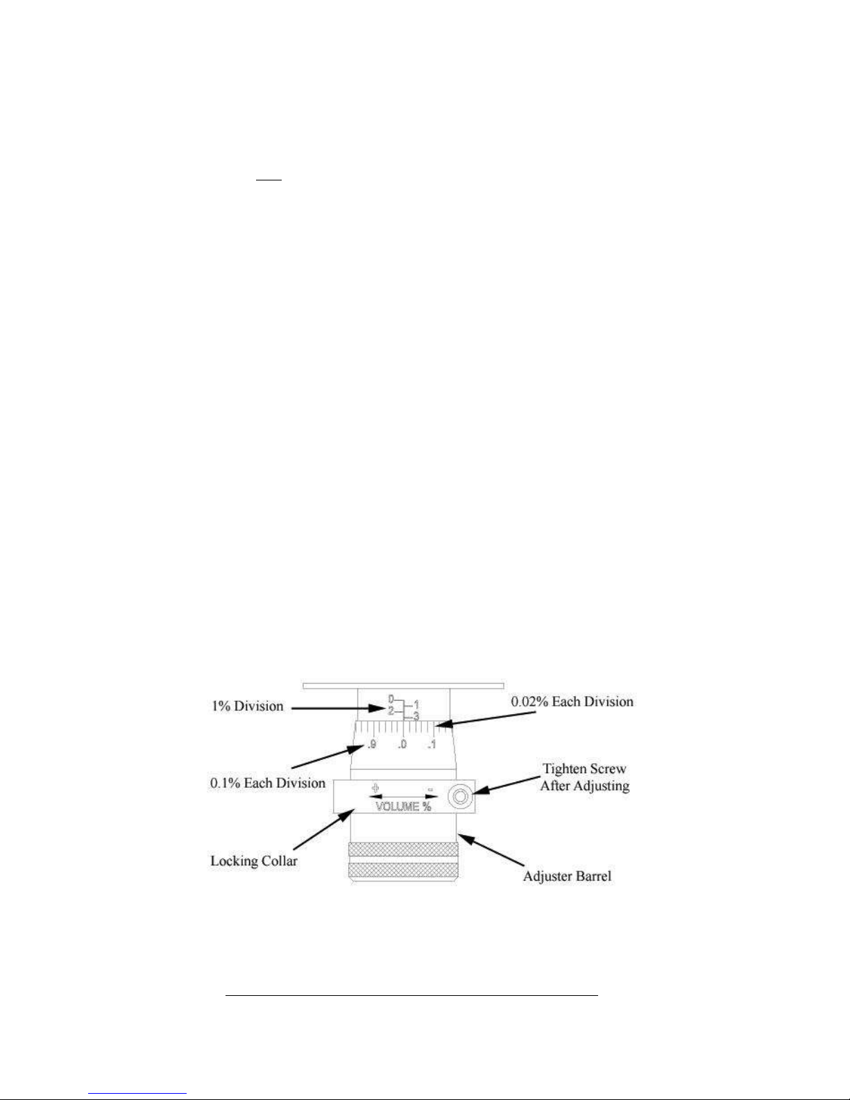
One complete turn of the adjuster barrel is equal to 1 gallon in 100 gallons or
1% of delivered volume. The adjuster body will show divisions of 1%, while
the adjuster barrel has divisions of 0.02%.
For volumes other than 100 gallons, the following formula may
be used to calculate the Adjuster percent to increase or decrease
prover volume.
Volume on Prover minus Volume on the Meter Counter
Volume on the Meter Counter
CALIBRATION PROCEDURE
1) Check for repeatability
A) Run a fast (high gallons per minute) test in your prover and record how much the meter is over or under
registering. Do NOT change the meter's calibration.
B) Run a slow (low gallons per minute) test and again record how much the meter is over or under registration.
If the results from the fast and the slow test are the same or close to the same, the meter can be successfully calibrated.
If the test results differ beyond the rated tolerance of the meter, then repairs are necessary before the meter can be
calibrated.
2) A valve or nozzle must be at the end of the delivery hose (at the prover).
3) Turn on the pump and purge the system of air. Leave the pump on.
4) Shut off the valve at the end of the delivery hose and let the system pressurize.
5) Wet the prover and empty it, letting it drip for 30 seconds.
6) Reset the register on the meter to "0".
7) Fill the prover to the line marked "0".
8) Calculate the percentage increase or decrease of registration required. For example, if a 50-gallon test prover indicates
exactly 50 gallons have been run through the meter against a meter registration of 49.7 gallons, the percentage increase
of registration would be 0.6%. (3/10’s in 50 gallons is 0.6%). If meter registration is less than the test prover measured
volume, an increase adjustment is required. If meter registration is greater than the test prover measured volume, a
decrease adjustment is required.
9) Remove the seal and seal wire.
10) Remove the front cover plate.
11) Loosen the screw on the clamping ring. The adjuster barrel will now be free to rotate.
12) Each small hash mark corresponds to 0.02% adjustment. Each of the larger numbers on the rotating barrel corresponds
to 0.1%. The large numbers engraved into the adjuster body correspond to 1%. The entire range of adjustment is 5%,
with the meter being set at the factory very close to the middle of this range.
13) To increase the registered volume, rotate the adjuster barrel to the left by the percentage increase desired. It is
recommended that the barrel be rotated 0.02% more than the desired amount and then backed down to the desired
figure. This accounts for any slack present in the adjuster mechanism. In the example above, the barrel would be
rotated 16 tick marks on the barrel (15 tick marks x 0.02 =0.3 = 3/10’s plus the one tick mark for slack). With the slack
removed, the barrel would then be rotated one tick mark back to the right to achieve the final adjustment.
14) To decrease the registered volume, the adjuster barrel is rotated to the right.
15) Tighten the screw and clamping ring.
16) Run another test and adjust if necessary.
17) When calibration is achieved, ensure that the screw and clamping ring are tight, and then replace the cover plate.
- 21-
Page 23
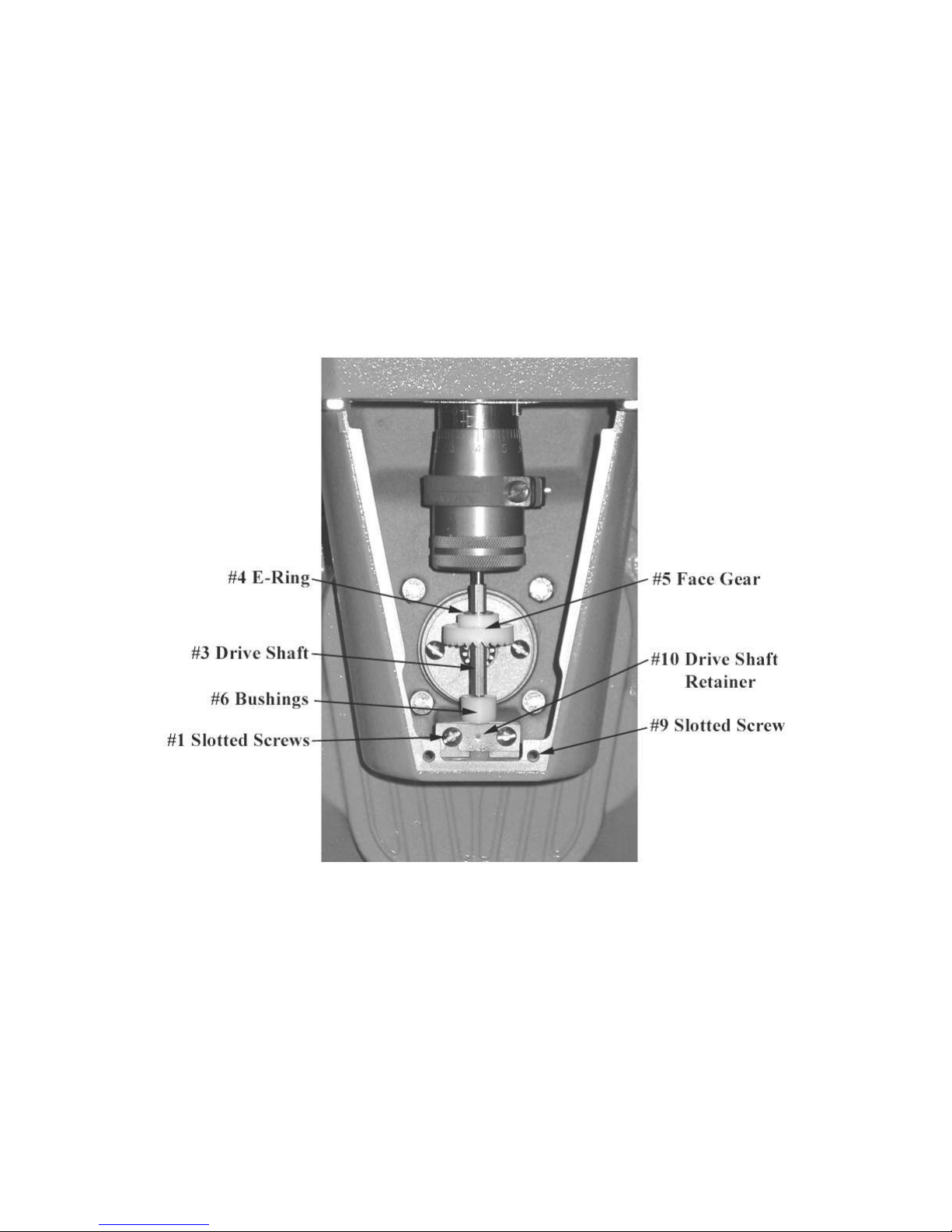
DIRECTION OF FLOW
The meter is set up at the factory for left to right flow. To change the meter to right to left flow, begin by
removing the screws (#9 on the Meter Assembly Breakdown in Service Manual) and the adjuster cover
plate (#7) on the front of the meter. Remove both the screws (#1), the drive shaft retainer (#10), the
bushings (#6), the drive shaft (#3), the e-ring (#4) and the face gear (#5). Reinstall the gear on the shaft
with the gear teeth facing up. Snap the e-ring back into place to hold the gear in place. Reinstall the
shaft, mating the face gear with the drive gear of the packing capsule assembly. Reinstall the screw and
cover plate. The meter will now be set up for right to left flow.
- 22 -
Page 24

Type
Housing
Rotors
Journals
Bearing
Sleeves*
Bearing
Plates
Timing
Gears
Packing Seal
Body/Flange
O-rings
Internal
Hardware
SP
Anodized
Aluminum
Anodized
Aluminum
Armolloy SS
Ni-Resist
Ni-Resist
Sintered SS
Viton®
Viton®
316 SS
SPA
Anodized
Aluminum
Anodized
Aluminum
Armolloy SS
Carbon
Graphite
Ni-Resist
Sintered SS
Viton®
Viton®
316 SS
SPD
Ductile Iron
Ni-Resist
Armolloy SS
Carbon
Graphite
Ni-Resist
Sintered SS
Simriz®
Teflon
®
316 SS
LP
Anodized
Aluminum
Anodized
Aluminum
Armolloy SS
Carbon
Graphite
Ni-Resist
Sintered SS
UL Buna N
UL Buna N
316 SS
IP
HC Anodized
Aluminum
HC Anodized
Aluminum
Armolloy SS
Illium 88
SS Alloy
17-4 SS
Sintered SS
Simriz
®
Teflon
®
316 SS
IC
HC Anodized
Aluminum
HC Anodized
Aluminum
Armolloy SS
Carbon
Graphite
17-4 SS
Sintered SS
Simriz
®
Teflon
®
316 SS
AF
Ductile Iron
Ni-Resist
Armolloy SS
Carbon
Graphite
316 SS
Sintered SS
Simriz
®
Teflon
®
316 SS
SS
316 SS
316 SS
Armolloy SS
Carbon
Graphite
316 SS
316 SS
Simriz
®
Teflon
®
316 SS
Product
Aluminum
Ductile Iron
Stainless
Steel
Ni-Resist
Carbon
Graphite
Ceramic
Buna-N
Viton
Simriz
Teflon
Acetone ■ ■ ■ ■ ■ ■ ■ ■
Anhydrous Ammonia
■ ■ ■ ■ ■ ■ ■ ■ ■ Avgas ■ ■ ■ ■ ■ ■ ■ ■ ■ ■
Bio-Diesel (B100)
■ ■ ■ ■ ■ ■ ■ ■ ■
■
Butane ■ ■ ■ ■ ■ ■ ■ ■ ■
Corn Syrup ■ ■ ■ ■ ■ ■ ■ ■
Diesel Fuel ■ ■ ■ ■ ■ ■ ■ ■ ■ ■
Epoxy ■ ■ ■ ■ ■ ■
Ethanol ■ ■ ■ ■ ■ ■ ■ ■ ■ ■
Fuel Oil ■ ■ ■ ■ ■ ■ ■ ■ ■ ■
Gasoline ■ ■ ■ ■ ■ ■ ■ ■ ■ ■
Glycerin ■ ■ ■ ■ ■ ■ ■ ■ ■ ■
Jet Fuel ■ ■ ■ ■ ■ ■ ■ ■ ■
Kerosene ■ ■ ■ ■ ■ ■ ■ ■ ■ ■
Latex ■ ■ ■ ■ ■ ■
Liquefied Petroleum Gas
■ ■ ■ ■ ■ ■ ■ ■ ■ Methanol ■ ■ ■ ■ ■ ■ ■ ■ ■
Methyl Ethyl Ketone
■ ■ ■ ■ ■ ■ ■ ■ Molasses ■ ■ ■ ■ ■ ■ ■ ■ ■ ■
Naptha ■ ■ ■ ■ ■ ■ ■ ■ ■
Nitrogen Fertilizer
■ ■ ■ ■ ■ ■ ■ ■ ■ ■ Nitric Acid (50%)
■ ■ ■ ■ Paraffin ■ ■ ■ ■ ■ ■ ■ ■
Potassium Carbonate
■ ■ ■ ■ ■ ■ ■ ■ Rosins ■ ■ ■ ■ ■ ■ ■
Sodium Chloride
■ ■ ■ ■ ■ ■ Stoddard Solvent
■ ■ ■ ■ ■ ■ ■ ■ ■ ■ Tallow ■ ■ ■ ■ ■ ■ ■ ■ ■
Tetrachoroethylene
■ ■ ■ ■ ■ ■ ■
■
Urea ■ ■ ■ ■ ■ ■
Varnish ■ ■ ■ ■ ■ ■
Vegetable Oil
■ ■ ■ ■ ■ ■ ■ ■ ■ ■ Water, Deionized
■ ■ ■ ■ ■ ■ ■ Xylene ■ ■ ■ ■ ■ ■ ■ ■ ■
700 SERIES METER CONSTRUCTION
*Ceramic bearing sleeves available upon request. Simriz is a registered trademark of Freudenberg-NOK.
Teflon is a registered trademark of Dupont Dow Elastomers, L.L.C.
Viton is a registered trademark of E.I. Dupont de Nemours & Co
QUICK COMPATIBILITY
- 23 -
Page 25

E = Excellent / Recommended
G = Good / Minor Effect
F = Fair / Moderate Effect
U = Not Recommended
This chart is intended as a chemical resistance guide rather than an unconditional rating since many system characteristics influence rate
of corrosion and operation of meter; such as solution, viscosity, concentration, temperature, lubricity, presence of solids, pressure and
flow rate. Ratings apply to liquids and solutions of commercial purity. Ratings do not imply Weights & Measures or UL conformance.
Ratings for food type materials do not imply FDA conformance. Information compiled is based on published data and research performed
by Total Control Systems. Total Control Systems cannot warranty, expressed or implied, that the laboratory results would be obtained
under actual operating conditions.
SOLUTION
VISCOSITY
SSU
SPECIFIC
GRAVITY
700 ROTARY METER
SP
SPA
SPD
LP
IP
IC
AF
SS
0-14-0, N-P-K SOLUTION
U U U U U U E
E
10-10-10, N-P-K SOLUTION
U U U U U U E
E
10-34-0, N-P-K SOLUTION
U U U U U U F
E
11-37-0, N-P-K SOLUTION
U U U U U U E
E
14-7-7, N-P-K SOLUTION
U U U U U U E
E
16-4-4, N-P-K SOLUTION
U U U U U U E
E
20-0-36, N-P-K SOLUTION
U U U U U U E
E
20-10-5, N-P-K SOLUTION
U U U U U U E
E
20-8-8, N-P-K SOLUTION
U U U U U U E
E
3-10-10, N-P-K SOLUTION
U U U U U U E
E
3-10-30, N-P-K SOLUTION
U U U U U U E
E
3-18-18, N-P-K SOLUTION
U U U U U U E
E
3-9-12, N-P-K SOLUTION
U U U U U U G
E
3-9-9, N-P-K SOLUTION
U U U U U U G
E
4-12-12, N-P-K SOLUTION
U U U U U U E
E
4-12-8, N-P-K SOLUTION
U U U U U U G
E
5-15-15, N-P-K SOLUTION
U U U U U U E
E
5-8-12, N-P-K SOLUTION
U U U U U U E
E
6-18-6, N-P-K SOLUTION
U U U U U U E
E
7-12-6, N-P-K SOLUTION
U U U U U U E
E
9-18-9, N-P-K SOLUTION
U U U U U U E
E
AATREX®, HERBICIDE
1.19
U U U U F U E
E
ACETALDEHYDE
0.783
U U U U G G G
E
ACETATE
0.9
U U U U G G G
E
ACETIC ACID
30
1.05
U U U U U U U
G
ACETIC ANHYDRITE
1.09
U U U U U U U
E
ACETONE
30
0.8
U U U U G G G
E
ACETYL CHLORIDE
1.11
U U U U U U G
E
ACRYLIC ACID
40
1.05
U U U U G G G
E
ACRYLIC ADHESIVES
U U U U G G G
E
ACRYLIC EMULSION
U U U U G G G
E
ACRYLIC ESTER
U U U U G G G
E
ACRYLIC RESIN
U U U U G G G
E
ACRYLONITRILE
100
0.8
U U U U G G G
E
ADBLUE
U U F U U U F
E
ADHESIVES
U U U U G G G
G
AIR (LIQUID CRYOGENIC)
U U U U U U U
U
ALCOHOL
U U G U U G G
E
ALCOHOL, ALLYL
0.852
U U U U U U U
E
ALCOHOL, AMYL
0.817
U U G U F G G
E
ALCOHOL, BEER (NOT SANITARY)
32
1.01
U U U U U U U
G
ALCOHOL, BENZYL
1.04
U U G U F G G
E
ALCOHOL, BUTYL
0.8109
U U G U F G G
E
ALCOHOL, DENATURED
U U G U F G G
E
ALCOHOL, DIACETONE
0.94
U U G U F G G
E
ALCOHOL, ETHYL
30
0.816
U G E U U G G
E
ALCOHOL, ETHYLENE
1.115
U F E U U G G
E
ALCOHOL, ISOBUTYL
0.806
U U G U F G G
E
ALCOHOL, ISOPROPYL
0.7863
G U G U F G G
E
ALCOHOL, METHYL
30
0.79
U U E U U G G
E
ALCOHOL, POLYVINYL
5000 - 50000
1.31
U U G U F G G
E
- 24 -
Page 26

E = Excellent / Recommended
G = Good / Minor Effect
F = Fair / Moderate Effect
U = Not Recommended
This chart is intended as a chemical resistance guide rather than an unconditional rating since many system characteristics influence rate
of corrosion and operation of meter; such as solution, viscosity, concentration, temperature, lubricity, presence of solids, pressure and
flow rate. Ratings apply to liquids and solutions of commercial purity. Ratings do not imply Weights & Measures or UL conformance.
Ratings for food type materials do not imply FDA conformance. Information compiled is based on published data and research performed
by Total Control Systems. Total Control Systems cannot warranty, expressed or implied, that the laboratory results would be obtained
under actual operating conditions.
SOLUTION
VISCOSITY
SSU
SPECIFIC
GRAVITY
700 ROTARY METER
SP
SPA
SPD
LP
IP
IC
AF
SS
ALCOHOL, PROPYL
0.804
G U G U F G G
E
ALCOHOL, WHISKEY (NOT SANITARY)
150
U U U U U U U
E
ALCOHOL, WINE (NOT SANITARY)
U U U U U U U
E
ALKALI SOLUTION
U U U U U U G
E
ALKYD RESINS
50000
U U U U G G G
E
ALUMINUM CHLORIDE
2.44
U U U U U U U
U
ALUMINUM HYDROXIDE (10%)
2.42
U U U U U U U
E
ALUMINUM NITRATE
U U U U U U U
E
ALUMINUM SULFATE (50%, 125F)
2.71
U U U U U U U
F
AMINES
U U U U U U G
F
AMMONIA (32%)
0.99
U U U U U U G
E
AMMONIA, ANHYDROUS (NH3) (USE
TEFLON SEALS & COUNTER EXTENSION)
30
0.70
U U U G U U U
U
AMMONIUM CARBONATE
U U U U U U G
E
AMMONIUM CHLORIDE
50
1.05
U U U U U U U
G
AMMONIUM HYDROXIDE
30
0.99
U U U U U G G
E
AMMONIUM NITRATE
1.73
U U U U G G F
E
AMMONIUM PHOSPHATE
50
1.62
U U U U U U U
F
AMMONIUM SULFATE
1.77
U U U U U U U
G
AMMONIUM SULFIDE
U U U U U U U
U
AMMONIUM SULFITE
1.41
U U U U U U U
U
AMYL ACETATE
30
0.88
U U U U U G G
G
ANILINE
40
1.02
U U U U U U G
E
ANIMAL FAT
U U U U U U G
E
ANITIFREEZE
88
1.10
E E E U E E E
E
ANTIMONY TRICHLORIDE
U U U U U U U
U
APPLE JUICE (NOT SANITARY)
1.06
U U U U U U U
E
AQUA AMMONIA
U U U U U U G
E
AQUA REGIA
U U U U U U U
U
AROMATIC SOLVENTS
U U E U E E E
E
ARSENIC ACID
50
2.0
U U U U U U U
G
ASPHALT (120F - 300F)
(USE HEAT EXTENSION & TRIM)
2400 - 12000
1.1 - 1.5
U U U U G U G
E
ASPHALT EMULSION (75F)
(WATER BASED MAY CONTAIN CLAY)
155 - 7000
1.0
U U U U G U G
E
AVIATION GASOLINE (AV GAS)
30
0.71
U E E U U E G
E
BACKDRAFT®, HERBICIDE
U U U U U U G
E
BARIUM HYDROXIDE
1.65
U U U U U U G
G
BARIUM NITRATE
3.24
U U U U U U F
E
BARIUM SULFATE
U U U U U U F
E
BARIUM SULFIDE
4.25
U U U U U U F
G
BARRICADE®, INSECTICIDE
U U U U U U E
E
BASAGRAN®, HERBICIDE
U U U U U F E
E
BEER
32
1.0
U U U U U U U
G
BEET SUGAR LIQUIDS
U U U U E U G
E
BENZALDEHYDE
40
1.05
U U U U U G G
E
BENZENE
31
0.90
U U U U F G G
G
BENZOIC ACID
1.27
U U U U G G U
G
BENZOL
1.04
U U U U G G G
G
BENZYL CHLORIDE
1.10
U U U U U U U
F
BICEP®, HERBICIDE
U U U U F F E
E
BIODIESEL FUEL (B100 @ 70F)
38
0.88
E E E U E E E
E
- 25 -
Page 27

E = Excellent / Recommended
G = Good / Minor Effect
F = Fair / Moderate Effect
U = Not Recommended
This chart is intended as a chemical resistance guide rather than an unconditional rating since many system characteristics influence rate
of corrosion and operation of meter; such as solution, viscosity, concentration, temperature, lubricity, presence of solids, pressure and
flow rate. Ratings apply to liquids and solutions of commercial purity. Ratings do not imply Weights & Measures or UL conformance.
Ratings for food type materials do not imply FDA conformance. Information compiled is based on published data and research performed
by Total Control Systems. Total Control Systems cannot warranty, expressed or implied, that the laboratory results would be obtained
under actual operating conditions.
SOLUTION
VISCOSITY
SSU
SPECIFIC
GRAVITY
700 ROTARY METER
SP
SPA
SPD
LP
IP
IC
AF
SS
BIPHENYL
1.0
U U U U G G G
E
BLEACH SOLUTION
U U U U U U U
U
BORAX
50
1.73
U U U U U U U
G
BOUNDARY®, HERBICIDE
U U U U F F E
E
BRAVO®, FUNGICIDE
U U U U U U G
E
BRINE SOLUTION
U U U U U U F
G
BROADSTRIKE™, HERBICIDE
U U U U F F E
E
BROMINE
3.11
U U U U U U U
U
BUCTRIL®, HERBICIDE
U U U U F F E
E
BUTADIENE (USE VITON OR TEFLON SEALS)
50
0.62
U U U E F G F
E
BUTANE
30
0.60
U U U E U U U
U
BUTANOL
30
0.81
U U U G U G G
E
BUTYL ACETATE
30
0.88
U U U U F G G
E
BUTYL ACRYLATE
50
0.90
U U U U F G U
G
BUTYL CARBITOL
0.95
U U U U F G G
E
BUTYL CELLOSOLVE
50
0.90
U U U U F G G
E
BUTYL PHTHALATE
1.05
U U U U F G G
E
BUTYLENE
0.60
U U U E F G G
E
CALCIUM CHLORIDE
50
1.23
U U U U U U F
G
CALCIUM HYDROXIDE
2.34
U U U U U U G
E
CALCIUM HYPOCHLORITE
U U U U U U U
U
CANE SUGAR LIQUIDS
225 - 5000
U U U U G U G
G
CAMIX®, HERBICIDE
U U U U U U U
G
CARBITOL
0.95
U U U U F G G
G
CARBON DIOXIDE
U U U U U U U
U
CARBON TETRACHLORIDE
30
1.59
U U U U F U F
G
CARMEL (NOT SANITARY)
1950
U U U U U U U
E
CATTLE FEED
U U U U U U G
E
CAUSTIC POTASH
U U U U U U G
E
CAUSTIC SODA (50%, 125F)
150
1.53
U U U U U U G
G
CELLOSOLVE
0.90
U U U U F G G
E
CHLORACETIC ACID
1.58
U U U U U U U
U
CHLORIC ACID
U U U U U U U
U
CHLORINATED SOLVENTS
U U U U U U G
G
CHLORINE
U U U U U U U
U
CHLOROBENZENE
30
1.10
U U U U U U G
E
CHLOROETHENE
0.91
U U U U U U G
E
CHLOROFORM
1.49
U U U U U U G
E
CHLOROPRENE
0.96
U U U U U U U
U
CHLOROSULPHONIC ACID
1.76
U U U U U U U
U
CHLOROTHENE
U U U U U U G
E
CHOCOLATE (NOT SANITARY)
50000 -100000
U U U U G U U
E
CHOLINE CHLORIDE
U U U U U U U
G
CHROMIC ACID
2.67
U U U U U U U
U
CHROMIUM SULFATE
1.70
U U U U U U U
G
CIDER (NOT SANITARY)
U U U U U U U
E
CITRIC ACID (30%, 75F)
50
1.54
U U U U U U U
E
CLARITY®, HERBICIDE
U U U U F F E
E
COAL TAR EMULSION
3000 - 8000
1.2
U U U U G F F
G
COBALT NITRATE (COBALTOUS)
1.88
U U U U U U U
G
COCOA BUTTER
0.86
U U U U G U F
E
- 26 -
Page 28

E = Excellent / Recommended
G = Good / Minor Effect
F = Fair / Moderate Effect
U = Not Recommended
This chart is intended as a chemical resistance guide rather than an unconditional rating since many system characteristics influence rate
of corrosion and operation of meter; such as solution, viscosity, concentration, temperature, lubricity, presence of solids, pressure and
flow rate. Ratings apply to liquids and solutions of commercial purity. Ratings do not imply Weights & Measures or UL conformance.
Ratings for food type materials do not imply FDA conformance. Information compiled is based on published data and research performed
by Total Control Systems. Total Control Systems cannot warranty, expressed or implied, that the laboratory results would be obtained
under actual operating conditions.
SOLUTION
VISCOSITY
SSU
SPECIFIC
GRAVITY
700 ROTARY METER
SP
SPA
SPD
LP
IP
IC
AF
SS
COMMAND®, HERBICIDE
U U U U F F E
E
COPPER CHLORIDE
3.38
U U U U U U U
U
COPPER CYANIDE
U U U U U U U
U
COPPER NITRATE
50
2.17
U U U U U U U
G
COPPER SULFATE
50
2.28
U U U U U U U
G
CORN EXTRACTIVE, FERMENTED
10000
1.20
U U U U G G G
E
CORN STARCH
150 - 1400
1.20
U U U U U U U
U
CORN SYRUP (NOT SANITARY)
5000 - 500000
1.35
U U U U G U G
E
CORNSWEET (NOT SANITARY)
740
1.35
U U U U G U G
E
COTTONQUICK®, DEFOLIANT
U U U U U U U
E
CRANBERRY JUICE (NOT SANITARY)
U U U U U U U
E
CREOSOTE (COAL TAR)
300
1.08
U U U U G F F
G
CRESYLIC ACID (CRESOL)
U U U U U U U
G
CROP OILS
100
1.04
G G E U G G E
E
CUMENE
0.86
U U U U F G G
E
CUTTING OILS
E E E U E E E
E
CYCLOHEXANE
50
0.78
U U U U F G G
E
CYCLOHEXANOL
0.94
U U U U F G G
E
CYCLOHEXANONE
0.94
U U U U F G G
G
CYCLONE® MAX, HERBICIDE
U U U U U U U
E
DEF®, DEFOLIANT
U U U U U U U
E
DEICING FLUID
1.15
G G G G G G G
G
DETERGENTS
1.20
U U U U U U G
E
DEXTROSE
U U U U G U U
E
DIAZINON, INSECTICIDE
U U U U U U E
E
DIBUTYL PHTHALATE
U U U U F G G
E
DICHLOROBENZENE
1.46
U U U U U U G
G
DICHLOROETHANE
1.26
U U U U U U G
G
DICHLOROPROPENE
1.23
U U U U U U G
E
DIESEL FUEL (LOW SULPHUR)
30 - 100
0.90
E E E U E E E
E
DIETHANOLAMINE
1.10
U U U U F G G
G
DIETHYL SULFATE
1.18
U U U U F G G
G
DIETHYLANILINE
0.96
U U U U F G G
E
DIETHYLBENZENE
0.865
U U U U F G G
G
DIETHYLENE GLYCOL
1.12
U U U U F G G
E
DIISOBUTYL KETONE
0.81
U U U U F G G
E
DIISOCYANATE
U U U U U U F
G
DIISOPROPYL KETONE
U U U U F G G
E
DIMETHYLAMINE
0.69
U U U U F G G
E
DIMETHYLFORMAHIDE
0.95
U U U U F G G
G
DIOCTYL PHTHALATE
320
0.99
U U U U F G G
G
DIPHENYL
1.0
U U U U F G G
G
DIPHENYL OXIDE
1.74
U U U U F G G
E
DIPROPYLENE GLYCOL
1.03
G G G U G G G
G
DIVINYLBENZENE
0.93
U U U U F G G
E
DOUBLEPLAY®, HERBICIDE
U U U U F F E
E
DOW THERM
E E E U E E E
E
DUAL®, HERBICIDE
U U U U F F E
E
DYE
U U U U U U U
E
EDTA
U U U U U U F
G
E-85 0.78
F G E U U G E
E
- 27 -
Page 29

E = Excellent / Recommended
G = Good / Minor Effect
F = Fair / Moderate Effect
U = Not Recommended
This chart is intended as a chemical resistance guide rather than an unconditional rating since many system characteristics influence rate
of corrosion and operation of meter; such as solution, viscosity, concentration, temperature, lubricity, presence of solids, pressure and
flow rate. Ratings apply to liquids and solutions of commercial purity. Ratings do not imply Weights & Measures or UL conformance.
Ratings for food type materials do not imply FDA conformance. Information compiled is based on published data and research performed
by Total Control Systems. Total Control Systems cannot warranty, expressed or implied, that the laboratory results would be obtained
under actual operating conditions.
SOLUTION
VISCOSITY
SSU
SPECIFIC
GRAVITY
700 ROTARY METER
SP
SPA
SPD
LP
IP
IC
AF
SS
EMULSION
G G G U G G G
E
ENAMEL
U U U U G G G
E
EPOXY
46500
1.15
U U U U G G G
G
EPOXY RESIN
U U U U G G G
G
EPTAM®, HERBICIDE
U U U U F F E
E
ETHANE
0.45
U U U E U U U
U
ETHANOL
30
0.79
U G E U U G E
E
ETHANOLAMINE
1.02
U U U U F G G
E
ETHER 0.69
U U U U U F G
G
ETHYL ACETATE
30
0.89
U U U U F G G
G
ETHYL ACRYLATE
0.92
U U U U U U U
E
ETHYL HEXANOIC ACID
0.91
U U U U U U U
G
ETHYLAMINE
0.69
U U U U U F F
G
ETHYLBENZENE
0.87
U U U U F G G
E
ETHYLENE CHLORIDE
30
1.26
U U U U U U G
E
ETHYLENE DIAMINE
30
0.90
U U U U U U G
E
ETHYLENE DIBROMIDE
2.17
U U U U U U U
E
ETHYLENE DICHLORIDE
30
1.26
U U U U U U G
E
ETHYLENE GLYCOL
100
1.12
E E E U E E E
E
ETHYLENE OXIDE
30
0.87
U U U U U U U
U
ETHYLENE VINYL ACETATE
7000
U U U U U U U
E
EXTREME®, HERBICIDE
U U U U U U G
E
FATTY ACIDS
0.84
U U U U F F F
E
FERRIC CHLORIDE
2.80
U U U U U U U
U
FERRIC HYDROXIDE
3.40
U U U U U U U
U
FERRIC NITRATE
1.68
U U U U U U U
G
FERRIC SULFATE
50
2.10
U U U U U U U
G
FERROUS CHLORIDE
1.93
U U U U U U U
U
FERROUS SULFATE
1.90
U U U U U U U
G
FINISH HARVEST AID
U U U U U U U
G
FLUORINE
U U U U U U U
U
FLUOSILIC ACID
U U U U U U U
U
FORMALDEHYDE
30
0.82
U U U U F F U
G
FORMIC ACID
1.22
U U U U U U U
F
FREEDOM®, HERBICIDE
U U U U F F E
E
FREON® 11
< 30
1.48
U U U G U U U
U
FREON® 12
< 30
1.31
U U U G U U U
U
FREON® 13
U U U G U U U
U
FREON® 14
U U U G U U U
U
FREON® 21 (USE TEFLON SEALS)
< 30
1.37
U U U G U U U
U
FREON® 22(USE TEFLON SEALS)
< 30
1.12
U U U G U U U
U
FREON® 31 (USE TEFLON SEALS)
U U U G U U U
U
FREON® 112 (USE TEFLON SEALS)
< 30
1.63
U U U G U U U
U
FREON® 113
< 30
1.57
U U U G U U U
U
FREON® 114
< 30
1.46
U U U G U U U
U
FREON® 114B2 (USE TEFLON SEALS)
< 30
2.16
U U U G U U U
U
FREON® 115
< 30
1.29
U U U G U U U
U
FREON® 134A (USE TEFLON SEALS)
< 30
1.21
U U U G U U U
U
FRONTIER®, HERBICIDE
U U U U F F E
E
FUEL OIL #1
34
0.85
E E E U E E E
E
FUEL OIL #2
36
0.87
E E E U E E E
E
- 28 -
Page 30

E = Excellent / Recommended
G = Good / Minor Effect
F = Fair / Moderate Effect
U = Not Recommended
This chart is intended as a chemical resistance guide rather than an unconditional rating since many system characteristics influence rate
of corrosion and operation of meter; such as solution, viscosity, concentration, temperature, lubricity, presence of solids, pressure and
flow rate. Ratings apply to liquids and solutions of commercial purity. Ratings do not imply Weights & Measures or UL conformance.
Ratings for food type materials do not imply FDA conformance. Information compiled is based on published data and research performed
by Total Control Systems. Total Control Systems cannot warranty, expressed or implied, that the laboratory results would be obtained
under actual operating conditions.
SOLUTION
VISCOSITY
SSU
SPECIFIC
GRAVITY
700 ROTARY METER
SP
SPA
SPD
LP
IP
IC
AF
SS
FUEL OIL #3
0.9
E E E U E E E
E
FUEL OIL #4
105
0.95
E E E U E E E
E
FUEL OIL #6
2000 – 10000
0.97
E E E U E E E
E
FULTIME®, HERBICIDE
1280
1.16
U U U U F F E
E
FURAN RESIN
0.94
U U U U G F G
E
FURFURAL
50
1.16
U U U U F G G
G
GALAXY®, HERBICIDE
U U U U F F E
E
GASOHOL
30
0.72
F E E U F E E
E
GASOLINE
33
0.75
E E E U E E E
E
GLUCOSE
50000
1.40
U U U U G U G
E
GLUE
U U U U G F G
E
GLYCERIN (GLYCEROL)
5000
1.26
G G E U G G G
E
GLYCOL
50 - 200
1.11
E E E U E E E
E
GLYCOL ESTER
U G G U G G G
E
GLYPHOMAX® PLUS, HERBICIDE
U U U U U U G
G
GRAMOXONE® EXTRA, HERBICIDE
U U U U U U U
E
GRAZON®, HERBICIDE
U U U U F F E
E
GREASE
E E E U E E E
E
GUARDSMAN®, HERBICIDE
U U U U F F E
E
HARNESS®, HERBICIDE
U U U U F F E
E
HEPTANE
30
0.70
U U U U U G G
E
HEXANE
30
0.66
U U U U U G G
E
HYDROCARBON RESIN
U U U U U G G
E
HYDROCHLORIC ACID
U U U U U U U
U
HYDROGEN PEROXIDE
U U U U U U U
U
INK (CAN BE ABRASIVE)
500 - 50000
1.0 – 1.4
U U U U F F F
G
IODINE 4.98
U U U U U U U
U
ISOBUTYL ACETATE
0.87
U U U U F G G
E
ISOBUTYL KETONE
U U U U F G G
E
ISOCYANATE
1.20
U U U U F G G
E
ISOOCTANE
0.69
G G G U F G G
E
ISOPROPYL ACETATE
30
0.87
U U U U F G G
E
ISOPROPYL ETHER
30
0.72
U U U U F G G
E
JET FUEL
30
0.80
G E U U E E U
E
KEROSENE
34
0.81
E E E U E E E
E
KETCHUP (NOT SANITARY)
U U U U U U U
E
KETONES
U U U U U G G
E
LACQUER
100 - 100000
0.95
U U U U G G G
E
LACTIC ACID
1.20
U U U U U U U
G
LACTOL SPIRITS
G G G U F G G
E
LADDOK®, HERBICIDE
U U U U F F E
E
LANOLIN
U U U U G G G
E
LARD 0.95
U U U U G U G
E
LASSO®, HERBICIDE
U U U U F F E
E
LATEX (CONGEALS & SHEAR SENSITIVE)
15000
U U U U G G G
E
LATEX EMULSIONS (SHEAR SENSITIVE)
10000 - 100000
U U U U G G G
E
LEAD ACETATE
2.50
U U U U U U U
G
LEMON JUICE
U U U U U U U
E
LIBERTY®, HERBICIDE
U U U U F F E
E
LIGNUM SULFONATE
10000
1.20
G G G U F G G
E
LIME WATER
2.34
U U U U U U G
E
- 29 -
Page 31

E = Excellent / Recommended
G = Good / Minor Effect
F = Fair / Moderate Effect
U = Not Recommended
This chart is intended as a chemical resistance guide rather than an unconditional rating since many system characteristics influence rate
of corrosion and operation of meter; such as solution, viscosity, concentration, temperature, lubricity, presence of solids, pressure and
flow rate. Ratings apply to liquids and solutions of commercial purity. Ratings do not imply Weights & Measures or UL conformance.
Ratings for food type materials do not imply FDA conformance. Information compiled is based on published data and research performed
by Total Control Systems. Total Control Systems cannot warranty, expressed or implied, that the laboratory results would be obtained
under actual operating conditions.
SOLUTION
VISCOSITY
SSU
SPECIFIC
GRAVITY
700 ROTARY METER
SP
SPA
SPD
LP
IP
IC
AF
SS
LIQUID FEED (CAUSTIC)
U U U U U U U
E
LIQUID FEED (NEUTRAL)
U U U U U U G
E
LIQUIFIED NATURAL GAS (LNG)
U U U U U U U
U
LIQUIFIED PETROLEUM GAS (LPG)
30
0.50
U U U E U U U
U
LORSBAN® 4E, INSECTICIDE
U U U U U U E
E
LUMAX®, HERBICIDE
U U U U U U U
G
MAGNESIUM CHLORIDE
2.32
U U U U U U U
F
MAGNESIUM HYDROXIDE
2.36
U U U U U U G
E
MAGNESIUM NITRATE
1.46
U U U U U U U
G
MAGNESIUM SULFATE
50
1.68
U U U U F F F
G
MALATHION
1.23
U U U U F F E
E
MALEIC ACID
1.59
U U U U U U U
E
MALEIC ANHYDRIDE
1.30
U U U U U U U
G
MANEX®, FUNGICIDE
U U U U U U G
E
MARKSMAN®, HERBICIDE
U U U U F F E
E
MAYONNAISE (NOT SANITARY)
9400
U U U U U U U
E
METHANE
U U U U U U U
U
METHANOL
30
0.79
U U E U U G G
E
METHYL ACETATE
0.92
U U U U F G G
E
METHYL BROMIDE
1.73
U U U U U U F
G
METHYL CELLOSOLVE
0.97
U U U U F G G
E
METHYL CHLORIDE
0.92
U U U U U U U
G
METHYL CHLOROFORM
1.33
U U U U U U G
E
METHYL ETHYL KETONE (MEK)
30
0.82
U U U U U G G
E
METHYL ISOBUTYL KETONE
30
0.80
U U U U U G G
G
METHYL METHACRYLATE
30
0.95
U U U U F G F
E
METHYL PARATHION
U U U U F F E
E
METHYLENE CHLORIDE
0.92
U U U U U U U
G
METHYL-T-BUTYL ETHER (MTBE)
30
0.74
F G G U U G G
E
MICRO-NUTRIENTS (CAUSTIC)
U U E U U U U
E
MICRO-NUTRIENTS (NEUTRAL)
U G E U U U G
E
MINERAL SPIRITS
E E E U E E E
E
MOLASSES (CAUSTIC)
1000 - 100000
1.45
U U E U U U U
E
MOLASSES (NEUTRAL)
1000 - 100000
1.45
U G E U U U G
E
MONOCHLOROACETIC ACID
U U U U U U U
U
MONOCHLOROBENZENE
1.11
U U U U U U G
E
MONOETHANOLAMINE
0.69
U U U U U U G
E
MONOETHYLAMINE
0.69
U U U U U U G
E
MONOMERS
G G G U G G G
E
MURIATIC ACID
U U U U U U U
U
NAPHTHA
30
0.89
E E E U E E E
E
NAPHTHALENE
1.15
U U E U U U G
E
NAPHTHENIC ACID
U U U U U U F
E
NATURAL GASOLINE
U F E U U F E
E
NEOPENTYL GLYCOL
1.07
U U U U G G G
E
NICKEL AMMONIUM SULFATE
U U U U U U U
U
NICKEL CHLORIDE
3.55
U U U U U U U
G
NICKEL NITRATE
2.07
U U U U U U U
G
NICKEL SULFATE
2.0
U U U U U U U
G
NITRIC ACID
U U U U U U U
U
NITROBENZENE
30
1.20
U U U U G G G
E
- 30 -
Page 32

E = Excellent / Recommended
G = Good / Minor Effect
F = Fair / Moderate Effect
U = Not Recommended
This chart is intended as a chemical resistance guide rather than an unconditional rating since many system characteristics influence rate
of corrosion and operation of meter; such as solution, viscosity, concentration, temperature, lubricity, presence of solids, pressure and
flow rate. Ratings apply to liquids and solutions of commercial purity. Ratings do not imply Weights & Measures or UL conformance.
Ratings for food type materials do not imply FDA conformance. Information compiled is based on published data and research performed
by Total Control Systems. Total Control Systems cannot warranty, expressed or implied, that the laboratory results would be obtained
under actual operating conditions.
SOLUTION
VISCOSITY
SSU
SPECIFIC
GRAVITY
700 ROTARY METER
SP
SPA
SPD
LP
IP
IC
AF
SS
NITROGEN FERTILIZER (28%, 30% & 32%)
50
0.82
U U U U U F G
E
NONYLPHENOL
160
1.10
U U U U U U U
G
OIL DISTILLATE
E E E U E E E
E
OIL, BUNKER 'C'
2000 - 10000
0.90
E E E U E E E
E
OIL, CASTOR
1500
0.96
E E E U E E E
E
OIL, CHINAWOOD
1425
0.94
E E E U E E E
E
OIL, COCONUT
148
0.93
G G F U G G F
E
OIL, COD LIVER
150
0.93
E E E U E E E
E
OIL, COOKING
G G G U G G G
E
OIL, CORN
150
0.93
G G G U G G G
E
OIL, COTTONSEED
176
0.93
E E E U E E E
E
OIL, CRUDE (SOUR @ 5,000PPM SULFUR)
56
0.83
U U G U U U G
E
OIL, CRUDE (SWEET @ 500PPM SULFUR)
110
0.86
G G G U G G G
E
OIL, FISH
0.93
G G G U G G G
E
OIL, FURNACE
37
1.1
G G G U G G G
E
OIL, HYDRAULIC
E E E U E E E
E
OIL, LINSEED
500 - 1000
0.95
G G G U G G G
E
OIL, LUBRICATION
200 - 4000
0.88 - 0.94
E E E U E E E
E
OIL, MINERAL
50
1.03
G G G U G G G
E
OIL, OLIVE
200
0.91
G G G U G G G
E
OIL, PALM
500
0.95
G G G U G G G
E
OIL, PEANUT
195
0.92
G G G U G G G
E
OIL, PEAR
0.88
U U G U G G G
E
OIL, PINE
0.94
G G G U G G G
E
OIL, RAPESEED
600
0.92
G G G U G G G
E
OIL, RED
0.90
U U G U G G G
E
OIL, RICUM
0.97
G G G U G G G
E
OIL, ROSIN
1500
1.08
G G E U G G E
E
OIL, SOYA
190
0.91
G G G U G G G
E
OIL, SOYBEAN
350
0.93
E E E U E E E
E
OIL, SUNFLOWER
G G G U G G G
E
OIL, TALL
0.98
U U G U U U G
E
OIL, TRANSFORMER
E E E U E E E
E
OIL, TUNG
0.94
G G G U G G G
E
OIL, VEGETABLE
50
0.95
G G G U G G G
E
OIL, WASTE (CONSULT FACTORY)
U U U U U U U
U
OLEUM SPIRITS
1.84
E E E U E E E
E
OPTILL®, HERBICIDE
U U U U F F E
E
ORANGE JUICE (NOT SANITARY)
U U U U U U U
E
ORTHO DICHLOROBENZENE
30
1.29
U U U U U U G
G
ORTHO XYLENE
U U U U U G G
G
OUTLOOK®, HERBICIDE
U U U U U U G
G
OXALIC ACID
U U U U U U U
U
OXYGEN (LIQUID CRYOGENIC)
U U U U U U U
U
PAINT LATEX ACETATE
0.84
U U U U G G G
E
PAINT LATEX ACRYLIC
U U U U G G G
E
PAINT LATEX VINYL
U U U U G G G
E
PAINT, ENAMEL
U U U U G G G
E
PAINT, LACQUER
U U U U G G G
E
PAINT, OIL BASE
U U U U G G G
E
PARAFFIN (MAY BE HEATED UP TO 300F)
0.90
U U U U G G G
E
- 31 -
Page 33

E = Excellent / Recommended
G = Good / Minor Effect
F = Fair / Moderate Effect
U = Not Recommended
This chart is intended as a chemical resistance guide rather than an unconditional rating since many system characteristics influence rate
of corrosion and operation of meter; such as solution, viscosity, concentration, temperature, lubricity, presence of solids, pressure and
flow rate. Ratings apply to liquids and solutions of commercial purity. Ratings do not imply Weights & Measures or UL conformance.
Ratings for food type materials do not imply FDA conformance. Information compiled is based on published data and research performed
by Total Control Systems. Total Control Systems cannot warranty, expressed or implied, that the laboratory results would be obtained
under actual operating conditions.
SOLUTION
VISCOSITY
SSU
SPECIFIC
GRAVITY
700 ROTARY METER
SP
SPA
SPD
LP
IP
IC
AF
SS
PARAPLEX
17000
U U U U G G G
E
PEANUT BUTTER
10000 - 100000
1.20
U U U U U U U
G
PENTACHLOROPHENOL
U U U U U U G
E
PENTANE
30
0.63
U U U E U U U
U
PERCHLOROETHYLENE
30
1.63
U U U U U U G
E
PETROLEUM ETHER
0.60
F G G U U G G
E
PHENOL
1.07
U U U U F G G
G
PHOSPHORIC ACID (0-85%, 125F)
1.83
U U U U U U U
G
PHOSPHOROUS CHLORIDE
U U U U U U U
U
PHOSPHOROUS TRICHLORIDE
U U U U U U U
U
PHTHALIC ACID
1.59
U U U U G G U
G
PHTHALIC ANHYDRIDE
1.53
U U U U F G U
E
PITCH
G G G U G G G
E
PLASTICIZER (AVOID AIR CONTACT)
1.12
G G G U G G G
E
POAST®, HERBICIDE
U U U U F F E
E
POLYESTER RESIN
150000
U U U U G G G
E
POLYETHYLENE
0.90
U U U U G G G
E
POLYMER
4600
U U U U G G U
G
POLYOL
1500 - 100000
U U U U G G G
E
POLYPHOSPHORIC ACID
U U U U U U U
E
POLYPROPYLENE
0.90
G G G U G G G
E
POLYPROPYLENE GLYCOL (TYPE 4)
4400
1.00
G G G U G G G
E
POLYURETHANE RESIN
U U U U G G G
G
POLYVINYL ACETATE (PVAC)
1.19
U U U U G G G
E
POLYVINYL CHLORIDE (SUSPENSIONS)
U U U U U U G
E
POTASH 2.43
U U U U U U F
G
POTASSIUM BROMIDE
U U U U U U U
G
POTASSIUM CARBONATE (POTASH)
U U U U U U F
G
POTASSIUM HYDRATE
2.04
U U U U U U F
G
POTASSIUM HYDROXIDE
1.52
U U U U U U F
G
POTASSIUM HYPROCHLORITE
U U U U U U U
U
POTASSIUM NITRATE
2.11
U U U U U U G
G
POTASSIUM PHOSPHATE
U U U U U U G
G
POTASSIUM SULFATE
2.66
U U U U U U G
G
POUNCE®, INSECTICIDE
U U U U U U E
E
PREP®, DEFOLIANT
U U U U U U U
E
PRIMEXTRA®, HERBICIDE
U U U U F F E
E
PRINCEP®, HERBICIDE
U U U U F F E
E
PRINTING INK
G U U U G U G
G
PRIST 1.02
U U U U U U U
E
PROPANE, LIQUID (LPG)
25
0.51
U U U E U U U
U
PROPYL ACETATE
0.89
U U U U F G G
G
PROPYLENE (USE VITON SEALS)
227
0.51
U U U G U U U
U
PROPYLENE GLYCOL
300
1.04
G G G U G G G
E
PROPYLENE OXIDE
0.83
U U U U U U U
E
PROWL®, HERBICIDE
U U U U F F E
E
PURSUIT® PLUS, HERBICIDE
U U U U F F E
E
RESIN, PHENOLIC
U U U U G G G
E
RESIN (CAUSTIC)
U U U U U U G
E
RESIN (NEUTRAL)
U U U U G G G
E
ROOFING TAR
U U U U G U G
E
- 32 -
Page 34

E = Excellent / Recommended
G = Good / Minor Effect
F = Fair / Moderate Effect
U = Not Recommended
This chart is intended as a chemical resistance guide rather than an unconditional rating since many system characteristics influence rate
of corrosion and operation of meter; such as solution, viscosity, concentration, temperature, lubricity, presence of solids, pressure and
flow rate. Ratings apply to liquids and solutions of commercial purity. Ratings do not imply Weights & Measures or UL conformance.
Ratings for food type materials do not imply FDA conformance. Information compiled is based on published data and research performed
by Total Control Systems. Total Control Systems cannot warranty, expressed or implied, that the laboratory results would be obtained
under actual operating conditions.
SOLUTION
VISCOSITY
SSU
SPECIFIC
GRAVITY
700 ROTARY METER
SP
SPA
SPD
LP
IP
IC
AF
SS
ROSIN 1.08
U U U U G G G
E
ROUNDUP®, HERBICIDE
31
1.01
U U U U F F E
E
RUBBER SOLVENT
U U U U G G G
E
SALICYLIC ACID
1.44
U U U U U U U
G
SALT BRINE
U U U U U U U
E
SHELLAC
F G G U G G G
E
SHELL-SOL
U G G U U G G
E
SILICONE FLUIDS
G G G U G G G
E
SILVER BROMIDE
U U U U U U U
U
SILVER NITRATE
4.33
U U U U U U U
G
SOAP SOLUTION
U U U U U U F
E
SODA ASH SOLUTION
50
1.55
U U U U U U G
E
SODIUM ACETATE
1.53
U U U U U U F
G
SODIUM ALUMINATE
U U U U U U G
E
SODIUM BICARBONATE (50%)
2.16
U U U U U U F
G
SODIUM BROMIDE
2.18
U U U U U U U
G
SODIUM CARBONATE
1.15
U U U U U U G
E
SODIUM CHLORATE
U U U U U U U
G
SODIUM CHLORIDE
30
2.17
U U U U U U G
G
SODIUM CHROMATE
60
2.72
U U U U U U G
G
SODIUM DICHROMATE
2.52
U U U U U U U
G
SODIUM FLOURIDE
2.56
U U U U U U U
U
SODIUM HYDROXIDE (50%, 125F)
150
1.53
U U U U U U G
G
SODIUM HYPOCHLORITE
U U U U U U U
U
SODIUM METAPHOSPHATE
U U U U U U G
E
SODIUM NITRATE
1.36
U U U U U U G
E
SODIUM PHOSPHATE
1.62
U U U U U U G
G
SODIUM SILICATE (AVOID AIR CONTACT)
1.56
U U U U U U G
E
SODIUM SULFATE
1.46
U U U U U U U
G
SODIUM SULFIDE
1.86
U U U U U U U
G
SODIUM SULFITE
U U U U U U U
G
SODIUM THIOSULFATE
1.23
U U U U G G U
E
SODIUM XYLENE SULFONATE
U U U U U U U
G
SONALAN®, HERBICIDE
U U U U F F E
E
STANNIC CHLORIDE
2.28
U U U U U U U
U
STARCH
100 - 100000
1.50
U U U U E E E
E
STARFIRE®, HERBICIDE
U U U U U U U
E
STEAM CONDENSATE
U U U U U U U
U
STEARIC ACID
0.84
U U U U G F U
E
STODDARD SOLVENT
30
0.78
E E E U E E E
E
STYRENE
0.90
E E E U E E E
E
SUGAR 1.69
U U U U G U G
E
SULFONIC ACID
U U U U U U F
E
SULFUR DIOXIDE
U U U U U U U
G
SULFURIC ACID (0-10% & 90-100%, 125F)
200
1.84
U U U U U U U
G
SULFURIC ACID, FUMING
U U U U U U U
U
SULFUROUS ACID
50
1.03
U U U U U U U
G
SULPHITE LIQUOR
530
1.30
U U U U U U U
G
SUPER BOLL®, DEFOLIANT
U U U U U U U
E
SURFACTANT
U U U U U U E
E
SURPASS®, HERBICIDE
U U U U F F E
E
- 33 -
Page 35

E = Excellent / Recommended
G = Good / Minor Effect
F = Fair / Moderate Effect
U = Not Recommended
This chart is intended as a chemical resistance guide rather than an unconditional rating since many system characteristics influence rate
of corrosion and operation of meter; such as solution, viscosity, concentration, temperature, lubricity, presence of solids, pressure and
flow rate. Ratings apply to liquids and solutions of commercial purity. Ratings do not imply Weights & Measures or UL conformance.
Ratings for food type materials do not imply FDA conformance. Information compiled is based on published data and research performed
by Total Control Systems. Total Control Systems cannot warranty, expressed or implied, that the laboratory results would be obtained
under actual operating conditions.
SOLUTION
VISCOSITY
SSU
SPECIFIC
GRAVITY
700 ROTARY METER
SP
SPA
SPD
LP
IP
IC
AF
SS
TALLOW
0.86
U U U U G U G
E
TANNIC ACID
1.70
U U U U U U F
G
TAR
G U U U G U G
E
TELONE®, FUMIGANTS
1.21
U U U U U U U
G
TETRA ETHYL LEAD
1.63
U U E U F G E
E
TETRA METHYL LEAD
1.60
U U E U F G E
E
TETRACHLOROETHYLENE
1.59
U U U U U U G
E
TETRAHYDROFURAN
< 30
0.89
U U U U U U G
E
THERMA SEAL
U U U U U U U
U
THIONYL CHLORIDE
U U U U U U U
U
TITANIUM DIOXIDE (ABRASIVE)
U U U U U U U
U
TITANIUM TETRACHLORIDE
U U U U U U U
U
TOLUENE
30
0.87
U U U U F E E
E
TOLUENE DIISOCYANATE
100 - 500
1.22
U U U U U G G
E
TOLUOL
0.87
U U U U G E E
E
TOMATO PUREE (NON SANITARY)
U U U U U U U
G
TOPNOTCH™, HERBICIDE
U U U U F F E
E
TOUCHDOWN®, HERBICIDE
U U U U U U F
E
TOXEPHENE
1.66
U U U U U U U
G
TRANSMISSION FLUID
185
0.87
E E E U E E E
E
TREFLAN, HERBICIDE
U U U U U U E
E
TRIBUTYL PHOSPHATE
0.98
U U U U U U G
E
TRICHLOROACETIC ACID
U U U U U U U
U
TRICHLOROBENZENE
1.46
U U U U U U G
G
TRICHLOROETHANE
30
1.22
U U U U U U G
E
TRICHLOROETHYLENE
30
1.44
U U U U U U G
E
TRICRESYL PHOSPHATE
1.16
U U U U U U U
E
TRIETHANOLAMINE
30
1.13
U U U U F G G
E
TRIETHYLAMINE
0.73
U U U U U U G
G
TRIETHYLENE GLYCOL
250
1.13
U U U U G G G
E
TRIFLURALIN
U U U U U U G
E
TRIMETHYLPENTANE
0.69
U U U G U U U
U
TRISODIUM PHOSPHATE
1.62
U U U U U U G
G
TURPENTINE
50
0.87
E E E U E E E
E
UREA 1.34
U U U U U U G
E
URETHANE FOAM
U U U U U U G
G
URETHANE RESIN
U U U U U U G
E
VAPAM®, FUMIGANT
25
U U U U U U G
E
VARNISH
8000
0.90
G G G U G G G
E
VARSOL
32
0.80
G G G U G G G
E
VEGETABLE SHORTENING
150 - 1500
0.91
U U U U G U F
E
VINEGAR
1.04
U U U U U U U
E
VINYL ACETATE
30
0.93
U U U U F G G
E
VINYL CHLORIDE
0.92
U U U U U U G
E
VINYL TOLUENE
0.89
U U U U F G G
E
WARRIOR®, INSECTICIDE
U U U U U U E
E
WATER, ACID MINE
U U U U U U U
G
WATER, BOILER FEED
U U U U U U U
U
WATER, BRACKISH
U U U U U U U
G
WATER, CITY
8
1.0
U U U U U F U
G
WATER, DEIONIZED
8
1.0
U U U U U G U
G
- 34 -
Page 36

E = Excellent / Recommended
G = Good / Minor Effect
F = Fair / Moderate Effect
U = Not Recommended
This chart is intended as a chemical resistance guide rather than an unconditional rating since many system characteristics influence rate
of corrosion and operation of meter; such as solution, viscosity, concentration, temperature, lubricity, presence of solids, pressure and
flow rate. Ratings apply to liquids and solutions of commercial purity. Ratings do not imply Weights & Measures or UL conformance.
Ratings for food type materials do not imply FDA conformance. Information compiled is based on published data and research performed
by Total Control Systems. Total Control Systems cannot warranty, expressed or implied, that the laboratory results would be obtained
under actual operating conditions.
SOLUTION
VISCOSITY
SSU
SPECIFIC
GRAVITY
700 ROTARY METER
SP
SPA
SPD
LP
IP
IC
AF
SS
WATER, DEMINERALIZED
1.0
U U U U U G U
G
WATER, DISTILLED
U U U U U G U
G
WATER, FRESH
1.0
U U U U U F U
G
WATER, HARD
U U U U U F U
G
WATER, METHANOL
U U G U U G U
G
WATER, OILY
U U G U U G U
G
WATER, POTABLE
U U U U U F U
G
WATER, SALT
U U U U U U U
G
WATER, SEA
1.0
U U U U U U U
G
WATER, SOFT
U U U U U F U
G
WATER, TAP
U U U U U F U
G
WAX
G G G U G G G
G
WEEDMASTER®, HERBICIDE
U U U U U U E
E
WHEY
U U U U G G U
E
WHISKEY (NOT SANITARY)
150
U U U U U U U
E
WINE (NOT SANITARY)
30
0.96
U U U U U U U
E
WINDSHEILD WASHER FLUID
U U U U G G U
E
WOOD PRESERVATIVE
U U U U U U G
E
XYLENE
30
0.86
U U U U F G G
E
ZINC CHLORIDE
U U U U U U U
U
ZINC NITRATE
1.96
U U U U U U U
G
ZINC SULFATE
1.96
U U U U U U U
G
Vapam® is a registered trademark of AMVAC.
Basagran®, Clarity®, Frontier®, Galaxy®, Guardsman®, Laddok®, Marksman®, OpTill®, Outlook®, Poast®, Prowl®, Pursuit® Plus and Weedmaster® are registered trademarks of BASF Corp.
Buctril®, DEF®, Liberty® and Prep® are registered trademarks of BAYER CROPSCIENCES
Broadstrike™, FulTime®, Grazon®, Lorsban® 4E, Sonalan®, Telone® and TopNotch™ are trademarks of DOW AGROSCIENCES.
Command® and Pounce® are registered trademarks of FMC CORPORATION.
CottonQuick®, Manex® and Super Boll® is a registered trademark of GRIFFIN, L.L.C.
Freedom®, Harness®, Lasso® and Roundup® are registered trademarks of MONSANTO.
Aatrex®, Barricade®, Bicep®, Boundary®, Bravo®, Cyclone® Max, Diazinon®, DoublePlay®, Dual®, Eptam®, Gramaxone®, Primextra®, Princep®, Starfire®, Surpass®, Touchdown® and
Warrior® are registered trademarks of SYNGENTA CROP PROTECTION, INC.
- 35 -
Page 37

U.S. System to Metric System
Metric System to U.S. Systems
If You Know
To Find
Multiply By
If You Know
To Find
Multiply By
Length:
Base unit is the
mil
millimeter
0.0254
millimeter
mil
39.37
Meter
inch
millimeter
25.4
millimeter
inch
0.0394
foot
meter
0.3048
meter
foot
3.2808
yard
meter
0.9144
meter
yard
1.0936
mile
kilometer
1.6093
kilometer
mile
0.6214
Area:
Base unit is the
inch²
centimeter²
6.4516
centimeter²
inch²
0.155
Square Meter (m²)
foot²
centimeter²
929.03
centimeter²
foot²
0.0011
foot²
meter²
0.0929
meter²
foot²
10.7639
yard²
meter²
0.8361
meter²
yard²
1.1960
mile²
kilometer²
2.590
kilometer²
mile²
0.3861
Mass:
Base unit is the
ounce (advp.)
gram
28.3495
gram
ounce (advp.)
0.03527
Kilogram (kg)
pound
kilogram
0.4536
kilogram
pound
2.2046
pound
metric ton
0.00045
metric ton
pound
2204.6
short ton (US)
metric ton
0.9072
metric ton
short ton (US)
1.1023
Volume/Capacity:
Base unit is the
inch³
centimeter³
16.3871
centimeter³
inch³
0.061
Cubic Meter (m³)
fluid ounce
centimeter³
29.5735
centimeter³
fluid ounce
0.0338
quart (liquid)
liter
0.9464
liter
quart (liquid)
1.0567
gallon (US)
liter
3.7854
liter
gallon (US)
0.2642
gallon (US)
meter³
0.0038
meter³
gallon (US)
264.17
gallon (US)
gallon (UK)
0.8327
gallon (UK)
gallon (US)
1.20095
gallon (UK)
liter
4.456
liter
gallon (UK)
0.21997
gallon (UK)
meter³
0.00457
meter³
gallon (UK)
219.97
foot³
meter³
0.0283
meter³
foot³
35.3147
yard³
meter³
0.7646
meter³
yard³
1.3079
in³/lb
m³/kg
0.000036
m³/kg
in³/lb
27.680
ft³/lb
m³/kg
0.0624
m³/kg
ft³/lb
16.018
Density:
Base unit is the
lb/ft³
kg/m³
16.0185
kg/m³
lb/ft³
0.0624
Cubic Meter (m³)
lb/in³
g/cm³
27.68
g/cm³
lb/in³
0.03613
lb/gal (US)
kg/m³
119.8264
kg/m³
lb/gal (US)
0.008345
Pressure:
Base unit is the
psi
kPa
6.8948
kPa
psi
0.145
Pascal (P)
psi
bar
0.0689
bar
psi
14.51
in Hg (60 F)
kPa
3.377
kPa
in Hg (60 F)
0.2961
in H²O (60 F)
kPa
0.2488
kPa
in H²O (60 F)
4.0193
Temperature:
Base unit is the
in/(in * °F)
m/(m * °C)
1.8
m/(m * °C)
in/(in * °F)
0.556
Kelvin (K)
°F
°C
(°F - 32)/1.8
°C
°F
1.8°C + 32
°F K (°F + 459.67)/1.8
K
°F
1.8k - 459.67
Velocity:
Base unit is the
in/min
cm/s
0.0423
cm/s
in/min
23.6220
Meter per Second (m/s)
ft/s
m/s
0.3048
m/s
ft/s
3.2808
mi/hr
km/hr
1.6093
km/hr
mi/hr
0.6214
ASTM
Mesh
Size Opening
(inches)
Micron
Opening
20
0.0331
841
40
0.0165
420
80
0.0070
177
100
0.0059
149
200
0.0029
74
METRIC CONVERSION GUIDE
STRAINER SCREEN SIZE
- 36 -
Page 38

- 37 -
700 ROTARY FLOW METER
Size
Pulse Transmitter
Meter A
Meter C
Meter D
700-15
1/10th Register
1/1 Register
Plate/Shaft Mount
Direct Meter Mount
1:1 Reed Contact
1 pulse/unit
0.1 pulse/unit
N/A
N/A
N/A
N/A
N/A
N/A
10:1 Reed Contact
10 pulses/unit
1 pulse/unit
N/A
N/A
N/A
N/A
N/A
N/A
100:1 Solid State
100 pulses/unit
10 pulses/unit
305.9
Pulses/USG
78.8229
Pulses/LTR
358.286
Pulses/UKG
1223.7
Pulses/USG
323.3
Pulses/LTR
1474.3
Pulses/UKG
Size
Pulse Transmitter
Meter A
Meter C
Meter D
700-20/25
1/10th Register
1/1 Register
Plate/Shaft Mount
Direct Meter Mount
1:1 Reed Contact
1 pulse/unit
0.1 pulse/unit
N/A
N/A
N/A
N/A
N/A
N/A
10:1 Reed Contact
10 pulses/unit
1 pulse/unit
N/A
N/A
N/A
N/A
N/A
N/A
100:1 Solid State
100 pulses/unit
10 pulses/unit
277.8
Pulses/USG
73.0164
Pulses/LTR
331.893
Pulses/UKG
555.5
Pulses/USG
146.8
Pulses/LTR
669.3
Pulses/UKG
Size
Pulse Transmitter
Meter A
Meter C
Meter D
700-30/35
1/10th Register
1/1 Register
Plate/Shaft Mount
Direct Meter Mount
1:1 Reed Contact
1 pulse/unit
0.1 pulse/unit
N/A
N/A
N/A
N/A
N/A
N/A
10:1 Reed Contact
10 pulses/unit
1 pulse/unit
N/A
N/A
N/A
N/A
N/A
N/A
100:1 Solid State
100 pulses/unit
10 pulses/unit
102.9
Pulses/USG
26.9390
Pulses/LTR
122.450
Pulses/UKG
205.8
Pulses/USG
54.37
Pulses/LTR
248.0
Pulses/UKG
Size
Pulse Transmitter
Meter A
Meter C
Meter D
700-40/45
1/10th Register
1/1 Register
Plate/Shaft Mount
Direct Meter Mount
1:1 Reed Contact
1 pulse/unit
0.1 pulse/unit
N/A
N/A
N/A
N/A
N/A
N/A
10:1 Reed Contact
10 pulses/unit
1 pulse/unit
N/A
N/A
N/A
N/A
N/A
N/A
100:1 Solid State
100 pulses/unit
10 pulses/unit
37.1
Pulses/USG
9.67720
Pulses/LTR
43.9873
Pulses/UKG
74.2
Pulses/USG
19.6
Pulses/LTR
89.4
Pulses/UKG
METER A Standard meter assembly with Veeder Root mechanical registration.
METER B Standard meter assembly less the Veeder Root mechanical registration.
METER C Meter and drive shaft assembly less calibration adjuster and Veeder Root mechanical registration.
METER D Direct drive meter assembly with pulse transmitter.
Page 39

- 38 -
GEAR PLATE INFORMATION
TCS STANDARD
Meter
Packing
Gear
Units
Registration
Type
Shafts
Ratio:1
Inverse
Ratio
Rotation
Verification Test
Tenths
Reading
Whole
Reading
Gears
GEAR PLATES
VR
310450-237
700-15
4:1
US Gallons
1/10
7
Single
0.766
1.305
CCW
Rotate LEFT one (1) time
1.3
13.1
64-48-49
VR
324823-214
700-15
4:1
US Gallons - Preset
1/10
7
Double
0.766
1.305
CCW
Rotate LEFT one (1) time
1.3
13.1
64-48-49
VR
310450-524
700-15
4:1
US Gallons
Whole
5
Single
7.655
0.131
CCW
Rotate RIGHT one (1) time
0.1
1.3
35-69-35-69-33-33-65
VR
324823-510
700-15
4:1
US Gallons - Preset
Whole
5
Double
7.655
0.131
CCW
Rotate RIGHT one (1) time
0.1
1.3
35-69-35-69-33-33-65
VR
70854-260
700-15
4:1
Liters
Whole
7
Single
2.022
0.495
CCW
Rotate LEFT one (1) time
0.5
4.9
34-48-69
VR
324823-213
700-15
4:1
Liters - Preset
Whole
7
Double
2.022
0.495
CCW
Rotate LEFT one (1) time
0.5
4.9
34-48-69
VR
310450-522
700-15
4:1
Imperial Gallons
Whole
5
Single
9.183
0.109
CCW
Rotate LEFT one (1) time
0.1
1.1
28-70-49-80-28-34-63
VR
310450-238
700-20/25
2:1
US Gallons
1/10
7
Single
0.695
1.439
CCW
Rotate LEFT one (1) time
1.4
14.4
59-48-41
VR
324823-215
700-20/25
2:1
US Gallons - Preset
1/10
7
Double
0.695
1.439
CCW
Rotate LEFT one (1) time
1.4
14.4
59-48-41
VR
310450-521
700-20/25
2:1
US Gallons
Whole
5
Single
6.949
0.144
CCW
Rotate LEFT one (1) time
0.1
1.4
29-65-44-62-30-32-66
VR
324823-509
700-20/25
2:1
US Gallons - Preset
Whole
5
Double
6.949
0.144
CCW
Rotate LEFT one (1) time
0.1
1.4
29-65-44-62-30-32-66
VR
310450-523
700-20/25
2:1
Imperial Gallons
Whole
5
Single
8.338
0.120
CCW
Rotate RIGHT one (1) time
0.1
0.0
34-63-33-66-28-34-63
VR
310450-233
700-20/25
2:1
Liters
Whole
7
Single
1.836
0.545
CCW
Rotate LEFT one (1) time
0.5
5.4
31-46-57
VR
324823-204
700-20/25
2:1
Liters - Preset
Whole
7
Double
1.836
0.545
CCW
Rotate LEFT one (1) time
0.5
5.4
31-46-57
VR
310450-746
700-30/35
2:1
US Gallons
Whole
6
Single
2.575
0.388
CCW
Rotate LEFT one (1) time
0.4
3.9
43-69-43-69
VR
324823-712
700-30/35
2:1
US Gallons - Preset
Whole
6
Double
2.575
0.388
CCW
Rotate LEFT one (1) time
0.4
3.9
43-69-43-69
VR
310450-759
700-30/35
1:1
US Gallons
1/10
6
Single
0.515
1.942
CCW
Rotate RIGHT one (1) time
1.9
19.4
66-33-67-69
VR
310450-752
700-30/35
1:1
US Gallons - Preset
1/10
6
Double
0.515
1.942
CCW
Rotate RIGHT one (1) time
1.9
19.4
66-33-67-69
VR
310450-750
700-30/35
2:1
Imperial Gallons
Whole
6
Single
3.089
0.324
CCW
Rotate LEFT one (1) time
0.3
3.2
33-58-33-58
VR
326253-705
700-30/35
2:1
Liters
Whole
6
Single
0.680
1.470
CCW
Rotate LEFT one (1) time
1.5
14.7
50-68-64-32
VR
324823-711
700-30/35
2:1
Liters - Preset
Whole
6
Double
0.680
1.470
CCW
Rotate LEFT one (1) time
1.5
14.7
50-68-64-32
VR
326253-200
700-40/45
2:1
Dekaliter
Whole
7
Single
2.452
0.408
CCW
Rotate LEFT one (1) time
0.4
4.1
32-42-78
VR
324823-211
700-40/45
2:1
Dekaliter - Preset
Whole
7
Double
2.452
0.408
CCW
Rotate LEFT one (1) time
0.4
4.1
32-42-78
VR
310450-747
700-40/45
2:1
US Gallons
Whole
6
Single
0.929
1.076
CCW
Rotate LEFT one (1) time
1.1
10.8
54-49-43-44
VR
324823-713
700-40/45
2:1
US Gallons - Preset
Whole
6
Double
0.929
1.076
CCW
Rotate LEFT one (1) time
1.1
10.8
54-49-43-44
VR
310450-751
700-40/45
2:1
Imperial Gallons
Whole
6
Single
1.114
0.898
CCW
Rotate LEFT one (1) time
0.9
9.0
66-42-28-49
VR
326253-704
700-40/45
2:1
Liters
Whole
6
Single
0.245
4.078
CCW
Rotate LEFT one (1) time
4.1
40.8
57-28-60-30
VR
324823-710
700-40/45
2:1
Liters - Preset
Whole
6
Double
0.245
4.078
CCW
Rotate LEFT one (1) time
4.1
40.8
57-28-60-30
Page 40

- 39 -
APPROXIMATE WEIGHT
Pounds
(Kilograms)
TCS Flow Meter
V/R Register
Counter
V/R Preset
Counter
V/R Ticket
Printer
Mechanical
Preset Valve
Electronic
Preset Valve
Air Eliminator
(Inline)
Air Eliminator
& Strainer
Air Eliminator/
High Volume Strainer
Strainer
& Cover
Air Check
Valve
700-15
SP
21
(9.5)
12
(5.4)
10
(4.5)
12
(5.4) 7 (3.2)
13
(5.9)
-
17
(7.7)
-
9
(4.1) 7 (3.2)
SPA
21
(9.5)
12
(5.4)
10
(4.5)
12
(5.4) 7 (3.2)
13
(5.9)
-
17
(7.7)
-
9
(4.1) 7 (3.2)
IP
21
(9.5)
12
(5.4)
10
(4.5)
12
(5.4) 7 (3.2)
-
-
17
(7.7)
-
9
(4.1) 7 (3.2)
IC
21
(9.5)
12
(5.4)
10
(4.5)
12
(5.4) 7 (3.2)
-
-
17
(7.7)
-
9
(4.1) 7 (3.2)
700-20
SP
24
(11.8)
12
(5.4)
10
(4.5)
12
(5.4) 7 (3.2)
13
(5.9)
-
17
(7.7)
32
(14.5) 9 (4.1) 7 (3.2)
SPA
24
(11.8)
12
(5.4)
10
(4.5)
12
(5.4) 7 (3.2)
13
(5.9)
-
17
(7.7)
32
(14.5) 9 (4.1) 7 (3.2)
SPD
52
(22.7)
12
(5.4)
10
(4.5)
12
(5.4)
16
(7.3)
-
-
39
(17.8)
-
19
(8.6)
-
IP
24
(11.8)
12
(5.4)
10
(4.5)
12
(5.4) 7 (3.2)
-
-
17
(7.7)
-
9
(4.1) 7 (3.2)
IC
24
(11.8)
12
(5.4)
10
(4.5)
12
(5.4) 7 (3.2)
-
-
17
(7.7)
-
9
(4.1) 7 (3.2)
AF
52
(22.7)
12
(5.4)
10
(4.5)
12
(5.4)
16
(7.3)
-
-
39
(17.8)
-
19
(8.6)
-
SS
54
(22.7)
12
(5.4)
10
(4.5)
12
(5.4)
16
(7.3)
-
-
45
(20.4)
-
21
(9.5)
-
700-25
SPA
24
(11.8)
12
(5.4)
10
(4.5)
12
(5.4) 7 (3.2)
13
(5.9)
-
17
(7.7)
32
(14.5) 9 (4.1) 7 (3.2)
SPD
52
(22.7)
12
(5.4)
10
(4.5)
12
(5.4)
16
(7.3)
-
-
39
(17.8)
-
19
(8.6)
-
700-30
SP
53
(24.0)
12
(5.4)
10
(4.5)
12
(5.4)
12
(5.4)
17
(7.7)
-
20
(9.1)
37
(16.8)
13
(5.9)
12
(5.4)
SPA
53
(24.0)
12
(5.4)
10
(4.5)
12
(5.4)
12
(5.4)
17
(7.7)
-
20
(9.1)
37
(16.8)
13
(5.9)
12
(5.4)
SPD
125
(56.7)
12
(5.4)
10
(4.5)
12
(5.4)
- - -
59
(26.8)
-
38
(17.2)
-
IP
53
(24.0)
12
(5.4)
10
(4.5)
12
(5.4)
12
(5.4)
-
-
20
(9.1)
-
13
(5.9)
12
(5.4)
IC
53
(24.0)
12
(5.4)
10
(4.5)
12
(5.4)
12
(5.4)
-
-
20
(9.1)
-
13
(5.9)
12
(5.4)
AF
125
(56.7)
12
(5.4)
10
(4.5)
12
(5.4)
- - -
59
(26.8)
-
38
(17.2)
-
700-35
SPA
53
(24.0)
12
(5.4)
10
(4.5)
12
(5.4)
12
(5.4)
17
(7.7)
-
20
(9.1)
37
(16.8)
13
(5.9)
12
(5.4)
SPD
125
(56.7)
12
(5.4)
10
(4.5)
12
(5.4)
- - -
59
(26.8)
-
38
(17.2)
-
700-40
SP
110
(49.9)
12
(5.4)
10
(4.5)
12
(5.4)
17
(7.7)
-
134
(60.8)
32
(14.5)
-
25
(11.3)
-
SPA
110
(49.9)
12
(5.4)
10
(4.5)
12
(5.4)
17
(7.7)
-
134
(60.8)
32
(14.5)
-
25
(11.3)
-
SPD
275
(124.7)
12
(5.4)
10
(4.5)
12
(5.4)
-
144
(65.3)
74
(33.6)
-
53
(24.0)
-
IP
110
(49.9)
12
(5.4)
10
(4.5)
12
(5.4)
17
(7.7)
-
134
(60.8)
32
(14.5)
-
25
(11.3)
-
IC
110
(49.9)
12
(5.4)
10
(4.5)
12
(5.4)
17
(7.7)
-
134
(60.8)
32
(14.5)
-
25
(11.3)
-
AF
275
(124.7)
12
(5.4)
10
(4.5)
12
(5.4)
-
-
144
(65.3)
74
(33.6)
-
53
(24.0)
-
700-45
SPA
110
(49.9)
12
(5.4)
10
(4.5)
12
(5.4)
-
-
134
(60.8)
32
(14.5)
-
25
(11.3)
-
SPD
275
(124.7)
12
(5.4)
10
(4.5)
12
(5.4)
-
-
144
(65.3)
74
(33.6)
-
53
(24.0)
-
Page 41

GLOSSARY
Acceptance Test: A original test of a new device under carefully controlled conditions and with expert operators, to
determine that the device will comply with the accuracy requirements for Weights and Measures approval to be used
as a resale device.
Accessories (Auxiliary Equipment): Items used with a measuring device to facilitate the use of the information
obtained from it. Also, items furnished to improve its performance, such as strainers, air eliminators, valves, etc.
Accumulative: A term applied to indicating elements or recording elements to describe the fact that they are not
resettable to a zero indication in normal use.
Accuracy: Freedom from error, usually expressed in percentage.
Accuracy Curve: A graph or plotted curve showing the performance characteristics of a measuring device. The
information plotted is the amount of error at the rates of flow between the minimum and maximum rated capacity of
the device.
Adjustor: A ratio changing device which is used to obtain agreement between the indicated and/or recorded volume
and the actual volume measured. The ration may be either continuously variable or variable in increments.
Air Eliminator (Air Release) (Vapor Eliminator): A device installed upstream of the measuring device to avoid
measuring air or vapor. Air or vapor measured with liquid will result in registering a volume larger than the liquid
volume.
Air Separator: A device of the air eliminator type designed to include the capability of separating air or vapor
intimately mixed with the liquid. It may include one or more air eliminator mechanisms and usually incorporates a
greater volume or other means for achieving separation.
Air (Vapor) Control System: An arrangement of various elements intended to assist the air eliminator – or air
separator – by stopping or reducing flow of liquid when air or vapor is detected. May have various trade names.
Ambient Temperature: Literally, this is the temperature of the surroundings. It is usually used to denote the
temperature of the atmosphere in a given location at a specific time.
Analog Device: A device in which the indicated quantity is a constantly changing amount, which indicates directly
the amount being measured. An example is the pointer on a clock or a continuous motion type indicator. In reading
this for the delivered quantity, it may be necessary to estimate the fractional units.
Analog Device: A device in which the indicated quantity is a constantly changing amount, which indicates directly
the amount being measured. An example is the pointer on a clock or a continuous motion type indicator. In reading
this for the delivered quantity, it may be necessary to estimate the fractional units.
Back Pressure Valve: A device intended to maintain a desired minimum upstream pressure.
Bubble Point: The conditions of temperature and pressure under which a liquid will begin to form vapor.
Calibration: The procedure of setting or bringing a meter or a prover into agreement with an established standard.
Check Valve (Non-return Valve): A device designed to prevent a reversal of flow of liquid.
Clingage: The liquid film that adheres to the inside surface of a container after it has been emptied.
Coefficient of Expansion: A number usually expressed as a decimal that indicates the change of volume per unit of
volume per degree of temperature change.
- 40 -
Page 42

Counter (Register): A device which indicates a quantity related to the volume measured by the meter.
Delivery, Over – Delivery, Under: The terms, over-delivery and under-delivery, are commonly used to indicate the
kind of measuring error that is experienced.
Density, Relative: The relative density t1/t2 of a solid liquid substance is defined as the ratio of the mass of a given
volume of the substance at a temperature t1 to the mass of an equal volume of pure water at a temperature t2 (this
term replaces the normal term “specific gravity”).
Differential Pressure Valve: A device designed to maintain the total pressure in a system at a desired pressure higher
than the vapor pressure of the liquid when being metered.
Digital Device: A device in which the indication of the measured quantity changes by finite increments, which may
be units, fractions, or decimals.
Digital Signal: Transmitted information that takes the form of a series of individual distinct signals. These are
commonly called pulses.
Drainage Time: The drainage time for test measures and provers shall be 10 seconds for a capacity of 10 gallons or
less, and 30 seconds for capacities exceeding 10 gallons. Necessary to achieve uniform clingage film.
Error: The difference between the indicated value and the true value.
Flow Limiting Device (Flow Control): A device installed in the system to prevent the rate of flow through the meter
from exceeding the desired maximum flow rate.
Flow Meter: Commonly used to describe a liquid measuring device that indicates the rate of flow in terms of
velocity or as units of volume per unit of time.
Flow Range: The minimum and maximum flow rates established by the manufacturer to provide the maximum
meter performance and accuracy with long life. If exceeded, accuracy or meter life may be adversely affected.
Flow Rate (Rate of Flow): The rate of flow of liquid expressed in volume or mass units per unit of time.
Gravity, Specific: See Density, Relative.
Laminar Flow: Liquid flow in which the liquid elements travel along relatively straight parallel paths.
Low Vapor Pressure Liquid: A liquid, which at atmospheric pressure and temperature can be maintained in an open
system without boiling.
Maintenance Tolerance: A tolerance test made at the maximum discharge rate that maybe anticipated under the
conditions of installation after the initial acceptance testing has been successfully completed.
Master Meter: A meter used as a reference for testing other working meters.
Meniscus: The curved surface at the end of a liquid column.
Non-return Valve (Check Valve): A device designed to prevent a reversal of flow.
Normal Test: A test made at the maximum discharge rate that may be anticipated under the conditions of
installation. (If equipped with an automatic temperature compensator, the meter should be tested with the
temperature compensator deactivated.) Any additional test conducted at flow rates down to and including one-half
of the sum of the maximum discharge flow rate and the rated minimum discharge flow rate shall be considered
normal tests.
- 41 -
Page 43

Positive Displacement Meter: A meter in which the primary sensing element separates the liquid into measured
segments of know volume providing a shaft motion or other signal that can be used for indicating the volume
delivered.
Preset Device: An indicating device that can be preset for a desired quantity which will stop the flow automatically,
or provide a signal when the preselected quantity of liquid has been metered or “delivered”.
Pressure Loss (Pressure Drop) (Loss of Head) (Differential Pressure): The difference in pressure between the inlet
and outlet of a device while operating.
Prover (Proving Tank): Volumetric Type. A closed or open vessel designed especially for accurate determination of
the volume of a liquid delivered into or out of it during a meter run. The volume of liquid is either observed from
the liquid level in a gage proving glass or known from previous calibration of a fixed-volume vessel. The volume is
greater than ten gallons. See Test Measure.
Recording Element: A device designed to print the volume metered on a ticket, slip, tape, or card.
Reference Standard: A volumetric measure that has been verified to “contain” or to “deliver” a known volume and
which is used for establishing the volume of field and working standards.
Register (Counter): A device, which indicates the quantity measured by the meter.
Registration, Over – Registration, Under: The terms, over-registration and under-registration, are commonly used to
indicate the kind of measuring error that is experienced. Over-registration indicates the counter is registering a
greater volume than is delivered by the meter, and under-registration indicates that the meter is delivering more than
is registered on the counter.
Repeatability: A measure of the deviation as a series of test results from their mean value, all determinations being
carried out under identical conditions.
Special Test: Any test other than a “Normal” test. A special test is defined as a test “to develop the operating
characteristics of a liquid measuring device and any special elements and accessories attached to or associated with
the device. Special test of a measuring system shall be made at a minimum discharge rate of 20% of the marked
maximum discharge rate or at the minimum discharge rate marked on the device whichever is less.
Split Compartment Test: A test applied to a truck mounted metering system, which simulates the conditions
encountered in actual operation when one truck compartment is emptied during a delivering and the delivery is
completed from another compartment.
Strainer (Filter): A device equipped with a porous medium or wire mesh element to prevent particles of foreign
material from passing through a meter.
Test Measure: Vessels designed especially for the precision measurement of liquid having verified capacities of 1, 5,
or 10 gallons. These are usually certified for accuracy of measurement by the National Bureau of Standards.
Tolerance: The amount of error that will be allowed. It is a plus of minus value.
Torque Load: The power required of the meter for driving accessory equipment such as counters, printer, etc.
True Value: The theoretically correct amount. In every day use it is represented by the Standard being used for
comparison.
Vapor Eliminator (Vapor Release): A device installed upstream of the measuring device to avoid measuring air
and/or vapor.
- 42 -
Page 44

MATERIAL SAFETY DATA SHEET
24 HOUR EMERGENCY ASSISTANCE GENERAL MSDS ASSISTANCE
(260) 833-3173 (260) 484-0301
CODE: RPS
==================================================================================
HAZARD RATING> LEAST-0 SLIGHT-1 MODERATE-2 HIGH-3 EXTREME-4
==================================================================================
DR LUBRICANTS, INC. DATE: 01/21/06
4611 NEWAYGO ROAD, SUITE D
FORT WAYNE, IN 46808 TELEPHONE: (260) 484-0301
==================================================================================
SECTION I - PRODUCT IDENTIFICATION
==================================================================================
PRODUCT: RP 1039
==================================================================================
SECTION II - COMPOSITION AND HAZARDOUS INFORMATION*
==================================================================================
OCCUPATIONAL
WT. PERCENT EXPOSURE LIMITS
CHEMICAL NAME CAS NUMBER IS LESS THAN (TLV-TWA) (TLV-STEL)
PETROLEUM 64741-65-7 90.0 100MG/M3
HYDROCARBON
PETROLEUM 64742-53-6 10.0 5MG/M3
HYDROCARBON
*ITEMS NOT SHOWN ARE NOT LISTED IN THE OSHA - T.S.C.A. HAZARDOUS CHEMICALS LISTING.
==================================================================================
SECTION III - PHYSICAL DATA
==================================================================================
BOILING RANGE: NA VAPOR DENSITY: NA
ODOR: PETROLEUM ODOR EVAPORATION RATE: NA
APPEARANCE AMBER LIQUID SOLUBILITY: INSOLUBLE
VOLATILE BY WEIGHT: NA PRODUCT DENSITY: 0.790
VOLATILE BY VOLUME: NA
==================================================================================
SECTION IV - FIRE AND EXPLOSION HAZARD DATA
==================================================================================
FLAMMABILITY CLASSIFICATION: COMBUSTIBLE FLASH POINT: 150 F LEL:NA
(CLEVELAND OPEN CUP) UEL:NA
DOT: COMBUSTIBLE LIQUID
EXTINGUISHING MEDIA: CARBON DIOXIDE, DRY CHEMICAL, FOAM
- 43 -
Page 45

PRODUCT: RP 1039
PAGE - 2
==================================================================================
SECTION IV - FIRE AND EXPLOSION HAZARD DATA
==================================================================================
UNUSUAL FIRE AND EXPLOSION HAZARDS : DO NOT DIRECT A SOLID STREAM OF WATER ONTO
BURNING PRODUCT. THIS MAY CAUSE SPREADING AND INCREASE THE FIRES INTENSITY.
COMBUSTION MAY PRODUCE: OXIDES OF CARBON, AND INCOMPLETELY BURNED
HYDROCARBONS IN THE FORM OF FUMES AND SMOKE.
SPECIAL FIREFIGHTING PROCEDURES: WEAR A SELF-CONTAINED BREATHING APPARATUS WITH
FULL FACEPIECE.
==================================================================================
SECTION V - HEALTH HAZARD DATA
==================================================================================
EFFECTS OF OVER EXPOSURE: MAY CAUSE MILD EYE IRRITATION AND REDNESS. PROLONGED
OR REPEATED EXPOSURE TO THE SKIN MAY RESULT IN LOSS OF NATURAL OILS ACCOMPANIED
BY DRYNESS, CRACKING AND DERMATITIS. INGESTION MAY RESULT IN NAUSEA, DIARRHEA
AND GASTRO INTESTINAL IRRITATION. OVEREXPOSURE TO MIST MAY CAUSE UPPER
RESPIRATORY TRACT IRRITATION AND DIFFICULTY BREATHING.
MEDICAL CONDITIONS PRONE TO AGGRAVATION BY EXPOSURE: NONE KNOWN.
PRIMARY ROUTE(S) OF ENTRY: DERMAL INHALATION INGESTION.
EMERGENCY AND FIRST AID PROCEDURES: IN CASE OF EYE CONTACT, IMMEDIATELY FLUSH
EYES WITH CLEAN WATER FOR AT LEAST 15 MINUTES. IF EYE IRRITATION PERSISTS, CONTACT A
PHYSICIAN. IN CASE OF SKIN CONTACT, REMOVE ANY CONTAMINATED CLOTHING AND RINSE
SKIN THOROUGHLY WITH WATER FOR AT LEAST 15 MINUTES. IF SKIN IRRITATION PERSISTS,
CONTACT A PHYSICIAN. IN CASE OF OVEREXPOSURE TO MIST, REMOVE VICTIM TO FRESH AIR: IF
BREATHING IS DIFFICULT ADMINISTER OXYGEN: AND CONTACT A PHYSICIAN IMMEDIATELY. IF
PRODUCT IS INGESTED DO NOT INDUCE VOMITING: CONTACT A PHYSICIAN.
==================================================================================
SECTION VI - REACTIVITY DATA
==================================================================================
STABILITY: THIS PRODUCT IS STABLE UNDER NORMAL STORAGE CONDITIONS.
HAZARDOUS POLYMERIZATION: WILL NOT OCCUR UNDER NORMAL CONDITIONS.
HAZARDOUS DECOMPOSITION PRODUCTS: THERMAL DECOMPOSITION MAY RESULT IN THE
FORMATION OF: OXIDES OF CARBON, AND INCOMPLETELY BURNED HYDROCARBONS IN THE
FORM OF FUMES AND SMOKE.
CONDITIONS TO AVOID: AVOID CONTACT WITH OPEN FLAME, STORE IN ROOM TEMPERATURE
AREA.
- 44 -
Page 46

PRODUCT: RP 1039
PAGE - 3
INCOMPATIBILITY: AVOID CONTACT WITH STRONG OXIDIZING AND REDUCING AGENTS AND
STRONG ALKLI.
==================================================================================
SECTION VII - SPILL OR LEAK PROCEDURES
==================================================================================
STEPS TO BE TAKEN IN CASE MATERIAL IS RELEASED OR SPILLED: FOR SMALL SPILLS: SOAK UP
SPILL WITH ABSORBENT MATERIAL. FOR LARGE SPILLS: DIKE SPILL AND PUMP INTO DRUMS FOR
PROPER DISPOSAL.
WASTE DISPOSAL METHOD: DISPOSE OF IN ACCORDANCE WITH ALL LOCAL STATE AND FEDERAL
REGULATIONS.
==================================================================================
SECTION VIII - SAFE HANDLING AND USE INFORMATION
==================================================================================
RESPIRATORY PROTECTION: NORMALLY NOT REQUIRED, HOWEVER, WHEN THE TLV IS
EXCEEDED WEAR THE APPROPRICATE MSHA/NIOSH APPROVED RESPIRATOR.
VENTILATION: PROVIDE ADEQUATE VENTILATION (SUCH AS MECHANICAL OR LOCAL) TO
ASSURE TLV IS NOT EXCEEDED.
PROTECTIVE GLOVES: NORMALLY NOT REQUIRED, HOWEVER, IF HANDS ARE FREQUENTLY IN
FLUID WEAR OIL AND CHEMICAL IMPERVIOUS GLOVES.
EYE PROTECTION: SAFETY GLASSES REQUIRED FOR NORMAL USAGE, WEAR CHEMICAL
GOGGLES WHEN EXCESSIVE SPLASHING MAY OCCUR.
OTHER PROTECTIVE EQUIPMENT: NORMALLY NOT REQUIRED, HOWEVER, WHERE REPEATED
CONTACT OCCURS, WEAR IMPERVIOUS CLOTHING AND BOOTS.
HYGIENIC PRACTICES: FOLLOW STANDARD INDUSTRIAL HYGIENE PRACTICES. LAUNDER ANY
CONTAMINATED CLOTHING BEFORE RE-USE.
==================================================================================
SECTION IX - SPECIAL PRECAUTIONS
==================================================================================
PRECAUTIONS TO BE TAKEN IN HANDLING AND STORAGE: DO NOT STORE IN THE PRESENCE OF
HEAT, SPARKS, FLAME OR ANY OTHER SOURCES OF IGNITION. STORE AWAY FROM STRONG
OXIDIZING AGENTS. EMPTY DRUMS MAY CONTAIN PRODUCT RESIDUES. ALL SAFETY
PRECAUTIONS TAKEN WHEN HANDLING THIS PRODUCT SHOULD ALSO BE TAKEN WHEN
HANDLING EMPTY DRUMS AND CONTAINERS.
OTHER PRECAUTIONS: NONE
- 45 -
Page 47

PRODUCT: RP 1039
PAGE - 4
==================================================================================
SECTION X - HMIS/NFPA RATINGS
==================================================================================
HMIS:HEALTH:1 FLAMMABILITY:2 REACTIVITY:0 PERSONAL PROTECTION:C
NFPA:HEALTH:1 FLAMMABILITY:2 REACTIVITY:0 SPECIFIC HAZARD:
==================================================================================
SECTION XI - OTHER REGULATORY INFORMATION
==================================================================================
DOT HAZARDOUS: NATURAL DESCRIPTION:
==================================================================================
THE INFORMATION CONTAINED HEREIN IS, TO THE BEST OF OUR KNOWLEDGE AND BELIEF,
ACCURATE. HOWEVER, SINCE THE CONDITIONS OF HANDLING AND USE ARE BEYOND OUR
CONTROL, WE MAKE NO GUARANTEE OF RESULTS, AND ASSUME NO LIABILITY FOR DAMAGES
INCURRED BY USE OF THIS MATERIAL. IT IS THE RESPONSIBILITY OF THE USER TO COMPLY
WITH ALL APPLICABLE FEDERAL, STATE AND LOCAL LAWS AND REGULATIONS.
==================================================================================
- 46 -
Page 48

TCS900005
2515 Charleston Place • Fort Wayne, Indiana 46808 USA
+1 (800) 348-4753 • +1 (260) 484-0382 • Fax +1 (260) 484-9230
Total Control Systems
 Loading...