

Total Control Systems 700-20, 700-15, 700-25, 700 SERIES, 700-30 Engineering Manual
...
Toll: +1 (800) 348-4753
Tele: +1 (260) 484-0382
Fax: +1 (260) 484-9230
info@tcsmeters.com
www.tcsmeters.com
ENGINEERING MANUAL
700 SERIES ROTARY FLOW METER
© Total Control Systems 2007
Fort Wayne, Indiana U. S. A.

Page No.
Table of Contents
1
Quote and Purchase Specifications
2
Rotary Design
3
Meter Type Classification
4
Meter Selection Factors
Metrology
5
Accuracy
6
Material Compatibility
6
Flow Rate
6
Pressure
6
Temperature
7
Lubricity
7
Suspension and Suspended Solids
7
Foreign Materials
8
PH
8
Viscosity
8
Pressure Loss
9
Bearing Load
10
System Design
Plumbing Figuration
10
Slow Flooding of System
11
Protection From Debris
11
Calibration
11
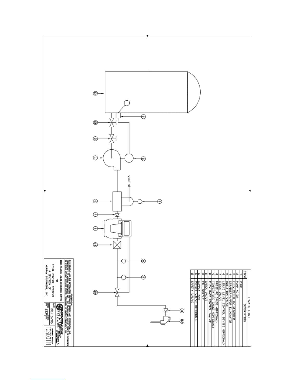
Drum Filling System
12
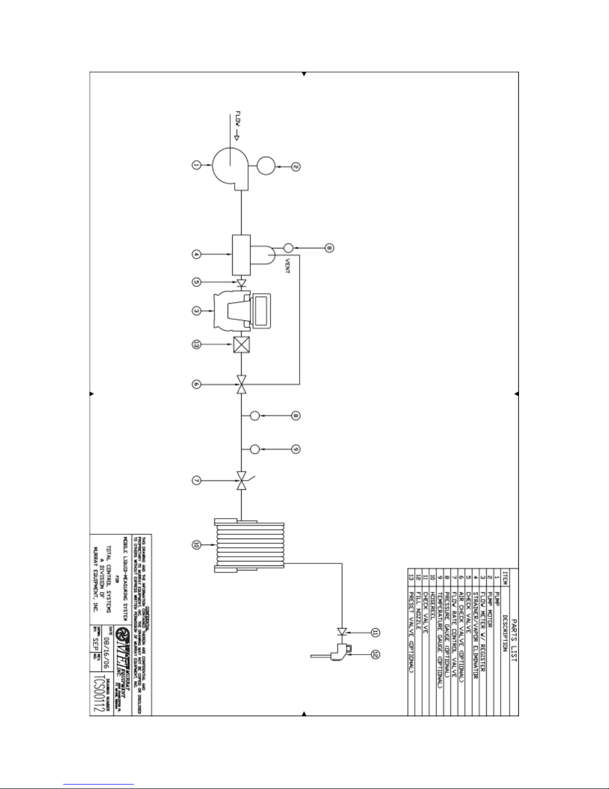
Mobile Fueling System
13
Hydraulic Shock
14
Thermal Expansion
14
Thermal Shock
14
Products that Dry/Congeal/Crystallize
14
LPG
14
Meter Calibration
16 - 18
Product Depletion (Split Compartment)
18 - 20
Calibration Procedure
21
Direction of Flow
22
700 Series Materials of Construction
23
Chemical Compatibility
23 - 35
Metric Conversion Guide
36
Registration Specifications
Gear Plate Information
37
Pulse Output
38
Approximate Weights
39
Glossary
40 - 42
Material Safety Data Sheet (MSDS) for Calibration Fluid
43 - 46
TABLE OF CONTENTS
- 1 -

QUOTE & PURCHASE SPECIFICATIONS
When issuing quote and purchase specifications and to assure you of receiving a Total Control
Systems meter with all of the many performance, installation, operating, and maintenance
advantages available only with a TCS meter. We suggest that 700 series meter-engineering
specifications include the following statements in addition to a TCS model number and
description.
“Meter shall be of a flow meter with a positive displacement design having rotary motion
without axial thrust or flow disruption. No eccentric, sliding, reciprocating or oscillating parts to
induce excess liquid shear or liquid compressibility within meter element. Meter shall have three
rotors that rotate in unison within the measuring chamber. Rotary parts to be horizontally
supported on both sides by solid support bearings and rotor journals of materials compatible with
product to be metered. Meter shall have stainless steel timing gears with no ball bearings, springs,
or cams. Rotary drive and meter adjustment output to all mechanical readout shall be capable of
infinite meter accuracy adjustment of 0.02% or better. Meter calibration adjustment device must
be externally accessible not requiring removal of any readout equipment for calibration or
replacement. Meter shall immediately respond to product low flow movement.”
NOTICE
Total Control Systems (TCS) shall not be liable for technical or editorial errors in this manual or
omissions from this manual. TCS makes no warranties, express or implied, including the
implied warranties of merchantability and fitness for a particular purpose with respect to this
manual and, in no event, shall TCS be liable for special or consequential damages including, but
not limited to, loss of production, loss of profits, etc.
The contents of this publication are presented for informational purposes only, and while every
effort has been made to ensure their accuracy, they are not to be construed as warranties or
guarantees, expressed or implied, regarding the products or services described herein or their use
or applicability. We reserve the right to modify or improve the designs or specifications of such
products at any time.
TCS does not assume responsibility for the selection, use or maintenance of any product.
Responsibility for proper selection, use and maintenance of any TCS product remains solely with
the purchaser and end-user.
All rights reserved. No part of this work may be reproduced or copied in any form or by any
means – graphic, electronic or mechanical – without first receiving the written permission of
Total Control Systems, Fort Wayne, Indiana USA.
- 2 -
DESIGN
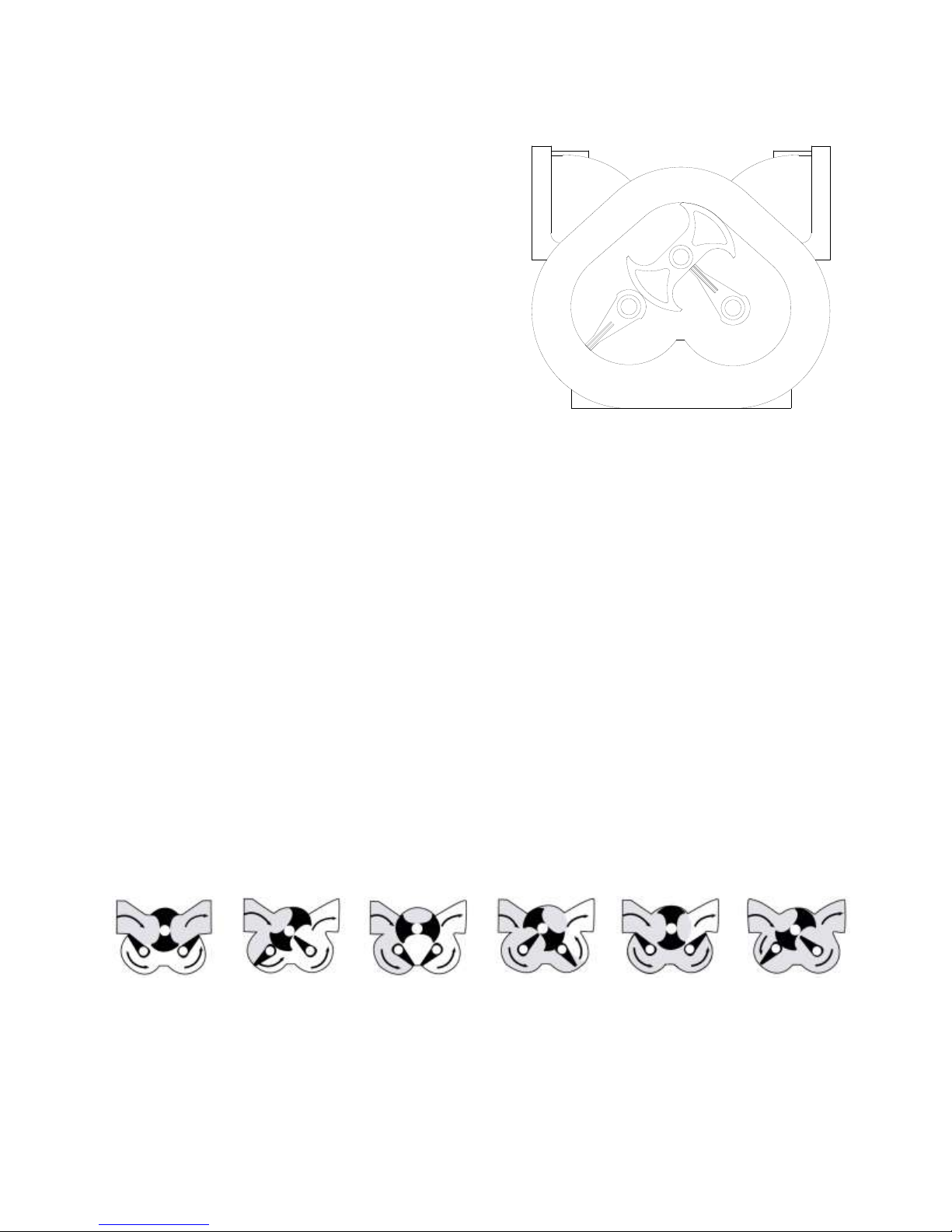
The TCS Model 700 series flow meter is a simple
and efficient design. The meter consists of a single
fluid chamber that contains a single blocking rotor
and two displacement rotors whose rotation is
synchronized with mating gears. As the fluid
enters the fluid chamber, the blocking rotor is
forced to rotate. The displacement rotors, also
rotating in conjunction with the blocking rotor help
direct the fluid flow through the chamber and to the
outlet. The linear flow of the fluid is thus
translated into rotary motion in the meter. The
output of the meter is picked up from the rotation
of the blocking rotor and transmitted to a register or
pulse transmitter.
The rotors in the meter are designed to operate at close tolerances to one another and the wall of
the fluid chamber. There are slight gaps between the rotors and the chamber wall. Because of
this, it is important that the meter be properly applied for the flow rate and operating pressure of
the system.
Because the fluid flowing through the meter is redirected only slightly from its natural flow,
there is very little pressure drop across the meter, unlike other meters that use multiple measuring
chambers.
The meter design uses high quality long life materials for the rotor bearings and journals. Since
there is no contact between the rotors and the fluid chamber wall, these critical components have
a long life expectancy.
Calibration of the meter involves adjusting the rotation of the output shaft relative to the rotation
of the internal rotors of the meter. This is accomplished by changing the settings on an adjuster
device. Calibration of the meter is discussed in detail in the section Meter Calibration.
700 METER FLOW ILLUSTRATION
- 3 -

METER TYPES
SP STANDARD PETROLEUM
For metering refined petroleum products such as Leaded and Unleaded Gasoline, Fuel Oils,
Diesel, Bio-Diesel, Kerosene, Vegetable Oils, Motor Oils, Ethylene Glycol (Antifreeze), etc.
SPA STANDARD PETROLEUM (AVIATION)
For metering refined petroleum products such as Aviation Gasoline, Jet Fuels, Gasoline, Fuel
Oils, Diesel, Bio-Diesel, Kerosene, Motor Oils, etc.
SPD STANDARD PETROLEUM (DUCTILE IRON)
For metering alternative fuels such as Natural Gasoline, Ethanol, Methanol, Bio-Diesel, Aviation
Gasoline, Fuel Oils, Diesel, Motor Oils, etc.
LP LIQUEFIED PETROLEUM
For metering Liquefied Petroleum Gas (LPG).
IP INDUSTRIAL PRODUCTS
For metering Food Products, Industrial Products, General Solvents and many other liquids; such
as Liquid Sugars, Corn Syrup, Soy Bean Oil, Shortenings, Latex Products, Adhesives, etc.
IC INDUSTRIAL PRODUCTS WITH CARBON BEARINGS
For metering Industrial Chemicals, General Solvents, Water and other Non-lubricating Liquids,
such as Alcohol, Acetones, Ethanol, Naphtha, Xylene, MEK, Toluene, Deionized Water,
Demineralized Water, Potable Water, etc.
AF ALL FERROUS
For metering Pesticides, Nitrogen Solutions, Fertilizer, Chlorinated Solvents, Paints, Inks,
Alcohols, Adhesives, Motor Oils, Molasses, Corn Syrup, Liquid Sugars, etc.
SS STAINLESS STEEL
For metering the same liquids as the SP, SPA, SPD, IP, IC and AF flow meters, but includes
food processing and special handling fluids such as Nitric, Phosphorus and Glacial Acetic Acids,
Anti-Icing Fluids, Vinegar, Fruit Juices, etc.
- 4 -

Meter
Type
Available
Flange
Connection*
Maximum
Capacity
Working
Pressure
Working
Temperature**
700-15
SP, SPA,
IP & IC
1½”NPT Flange;
2” optional
60 GPM
(227 LPM)
150 PSI
(10.5 BAR)
-40°F to 160°F
(-40°C to 71°C)
700-20
SP, SPA,
SPD, IP, IC,
AF & SS
2” NPT Flange;
1½”optional
100 GPM
(380 LPM)
150 PSI
(10.5 BAR)
-40°F to 160°F
(-40°C to 71°C)
700-20
LP
2” NPT Flange;
1½”optional
100 GPM
(380 LPM)
350 PSI
(24.1 BAR)
-30°F to 140°F
(-30°C to 60°C)
700-25
SPA, SPD
2” NPT Flange
150 GPM
(567 LPM)
150 PSI
(10.5 BAR)
-40°F to 160°F
(-40°C to 71°C)
700-30
SP, SPA,
SPD, IP, IC
& AF
3” NPT Flange
2”optional
200 GPM
(760 LPM)
150 PSI
(10.5 BAR)
-40°F to 160°F
(-40°C to 71°C)
700-35
SPA, SPD
3” NPT Flange
300 GPM
(1135 LPM)
150 PSI
(10.5 BAR)
-40°F to 160°F
(-40°C to 71°C)
700-40
SP, SPA,
SPD, IP, IC
& AF
4” NPT Flange;
3” optional
500 GPM
(1893 LPM)
150 PSI
(10.5 BAR)
-40°F to 160°F
(-40°C to 71°C)
700-45
SPA, SPD
4” NPT Flange
600 GPM
(2271 LPM)
150 PSI
(10.5 BAR)
-40°F to 160°F
(-40°C to 71°C)
METER OPERATING SPECIFICATIONS
* Flanged NPT is Standard; BSPT, Slip Weld, ANSI and others are available upon request.
** Higher working temperatures can be achieved at reduced pressures (consult factory for more information)
METER SELECTION FACTORS
WEIGHTS&MEASURES
Before any meter can be specified, knowledge of each application is required. If the liquid is to
be sold through a metered delivery, domestic or international certification from a governing body
may be required. Total Control Systems strictly adheres to all domestic and international
metrology conformance regulations for the custody transfer of fluids. For questions regarding
weights and measures approvals or other issues, please consult factory.
- 5 -

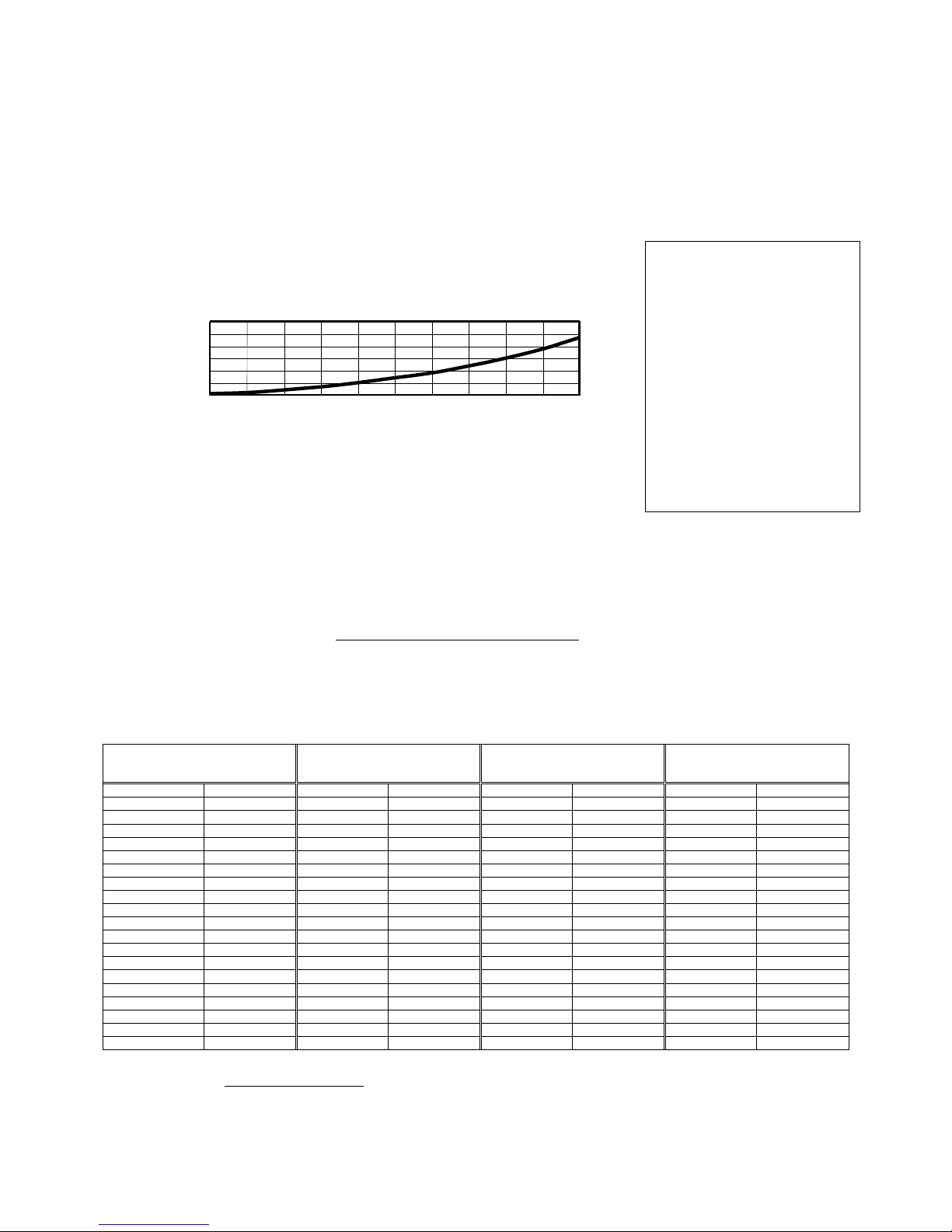
TYPICAL ACCURACY CURVE
-0.4
-0.2
0
0.2
0.4
0 10 20 30 40 50 60 70 80 90 100
PERCENT OF FLOW RATE
% DEVIATION
Gasoline
Fuel Oil
The 700-meter’s accuracy (percent of error over or under the zero – error level) remains within
design parameters (+/- 0.15%) over its minimum rated flow range to its maximum rated flow
range for custody transfer meter requirements. This percentage meets or exceeds the Wholesale
and Vehicle accuracy requirements for accurate custody transfer of product, as specified in the
National Institute of Standards and Technology (NIST) Handbook 44.
PRODUCT CHARACTERISTICS
A) Material Compatibility
The product intended to be measured must review Total Control Systems CHEMICAL
COMPATIBILITY on page 23 to 35 to find the suitable materials and meter type. Materials
incompatible with product will potentially reduce accuracy, operation life, contaminate liquid
and may be harmful to others.
B). Flow Rate
The minimum and maximum system rate of flow must be determined for the selection of
flow meter. The flow rate of the system is dependent upon the product viscosity; the desired
meter configuration, the systems pump capabilities, and the plumbing configuration.
C) Pressure
The maximum working pressure allowed should be reviewed under flow meter type and
pressure rating. All meters meet the European Pressure Equipment Directive (PED) No.
97/23/EC. Failure to adhere to the maximum allowable pressure may potentially cause a seal
leak or casting rupture.
-6 -

Meter Type
SP/SPA/SPD/IP/IC/AF/SS
LP
150F/150PSI
150F/350PSI
200F/100PSI
200F/275PSI
250F/75PSI
250F/250PSI
300F/50PSI
300F/150PSI
D) Temperature
The operating temperature has a great effect on the meter seals and its relationship to the
maximum pressure allowed with the flow meter castings. It will be necessary to reduce the
maximum rated working pressure as the operating temperature increases. Any metering
system operating over 160F (71C) will require extra clearance rotors to compensate for
material expansion. Any metering system operating over 180F (82 C) will require at least a
one (1) foot registration extension to protect the registration devices. Increase in temperature
may increase the corrosion rate of some products.
1) O-ring / Packing Seal Temperature Rating
UL Buna -20F to 140F -30C to 60C
UL Viton -104F to 221F -75C to 105C
Viton -31F to 400F -35C to 204C
Simriz -40F to 450F -10C to 230C
Teflon -20F to 500F -30C to 260C
The Acetyl Face Gear and Bushings, in the register support assembly;
maximum temperature is 180F (82C)
2) Pressure rating at elevated temperatures.
E) Lubricity
The lubricity or non-lubricity of the product will determine the bearing sleeve material
suitable for use. Products with no lubrication will require the use of Carbon Graphite or
Ceramic bearing sleeves. Products with lubrication will reduce friction between two metal
surfaces and help dissipate heat.
F) Suspensions & Suspended Solids
Products with a low percentage of soft suspensions or suspended solids will require clearance
rotors and/or Ceramic bearing sleeves to protect the meter from its abrasive effects. High
percentages (5%) of suspensions or suspended solids, or any hard solids, such as sand, are
not recommended for the 700 series meter. Due to the very tight machining tolerances any
solid, larger than the thickness of a piece of paper, has the potential of stopping the flow
through the meter and can cause damage to the meter.
- 7 -
pH SCALE
NEUTRAL
0 1 2 3 4 5 6 8 9
10
11
12
13
14
◄——— ACID REACTION ———
——— ALKALINE REACTION ——►
7
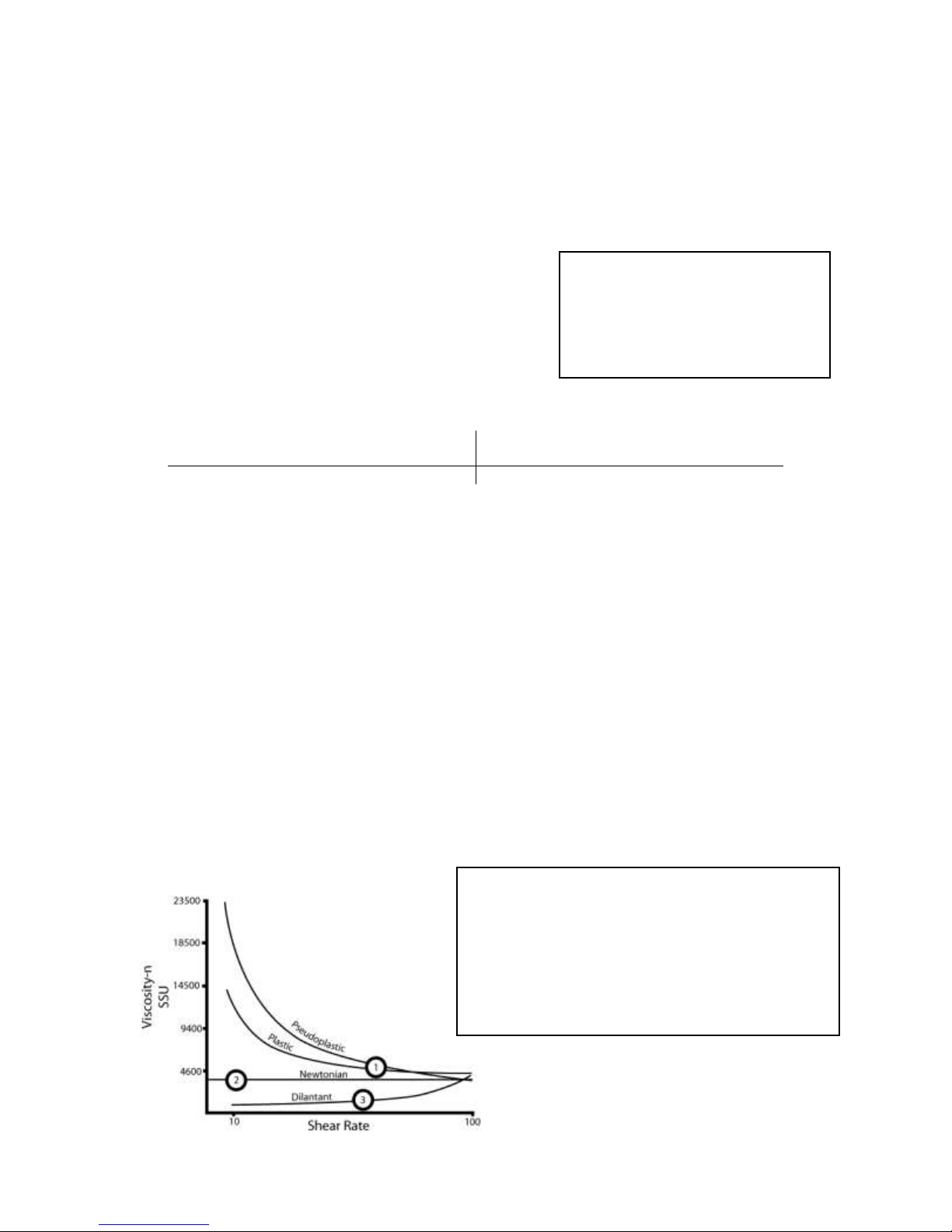
1) Thixotropic Liquids (Plastic and Peudoplastic)
Viscosity decreases as shear rate increases. Typical liquids include
Gels, Latex paints, lotions, Shortening, Mayonnaise, Printers Ink, Hand
cleaner and Yeast.
2) Newtonian Liquids – Viscosity remains unchanged with shear.
3) Dilatants Liquids – Viscosity increases as shear rate increases. Most
liquids in this category are unsuitable with PD flow meters; these
include Clay, Slurries and some confectionary bases.
Material pH
Aluminum 5 – 8
Ductile Iron 5.5 – 11
Ni-Resist 5.5 – 14
Stainless Steel 0 – 14
G) Foreign Materials
Products that are to be measured may have foreign materials present. The inlet side of any
positive displacement meter should be equipped with a strainer. Matching the strainer size or
one size larger, with an appropriate size screen will protect the meter and accessories from
damage in the system. A minimum of 40-mesh screen is recommended for petroleum service.
H) pH
The metal resistance to the effects of high or low
PH is difficult to calculate because of the varying
concentrations and corrosiveness of properties.
This is a generalized rating for pH resistance.
I) Viscosity
Viscosity is the property of a fluid that is a measure of its resistance to flow. Among the
earliest to express this quantitatively was Sir Isaac Newton. He reasoned that the viscosity of
a liquid was proportional to its shear stress (or resistance to shear). Liquids that behave in
this manner are referred to as “Newtonian” liquids and are typically by petroleum fluids,
water and similar chemicals.
Other types of fluids are grouped into a general category called “Non-Newtonian” which
includes dilatants, plastic, pseudoplastic and thixotropic. Liquids in this group are
characterized by viscosity that changes with the rate of shear as compared to the NonNewtonian fluids where viscosity is basically constant with shear and flow rate. As a
consequence, Newtonian fluids are much easier to predict with regard to their performance
through a flow meter than are the Non-Newtonian liquids.
Many of the more viscous liquids pumped through the 700 series rotary flow meter are
plastic and pseudoplastic and as such are reduced in effective viscosity after being presheared by the pump. The diagram below shows how viscosity varies as a function of shear
rate on various types of liquids.
- 8 -
PRESSURE DROP CURVE
32 SSU SOLVENT
0
0.5
1
1.5
2
2.5
3
0 10 20 30 40 50 60 70 80 90 100
PERCENT OF FLOW RATE
P.S.I.
SSU SSU SSU SSU
CPS
Saybolt
CPS
Saybolt
CPS
Saybolt
CPS
Saybolt
Centipoise
Universal
Centipoise
Universal
Centipoise
Universal
Centipoise
Universal 1 31
200
1,000
900
4,300
7,000
32,500 2 34
220
1,100
1,000
4,600
8,000
37,000
4
38
240
1,200
1,200
5,620
8,500
39,500
7
47
260
1,280
1,300
6,100
9,000
41,080
10
60
280
1,380
1,400
6,480
9,500
43,000
15
80
300
1,475
1,500
7,000
10,000
46,500
20
100
320
1,530
1,700
8,000
15,000
69,400
25
130
340
1,630
1,800
8,500
20,000
92,500
30
160
360
1,730
1,900
9,000
30,000
138,500
40
210
380
1,850
2,000
9,400
40,000
185,000
50
260
400
1,950
2,200
10,300
50,000
231,000
60
320
420
2,050
2,400
11,200
60,000
277,500
70
370
440
2,160
2,500
11,600
70,000
323,500
80
430
460
2,270
3,000
14,500
80,000
370,000
90
480
480
2,380
3,500
16,500
90,000
415,500
100
530
500
2,480
4,000
18,500
100,000
462,000
120
580
550
2,660
5,000
23,500
125,000
578,000
140
690
600
2,900
5,500
26,000
150,000
694,000
160
790
700
3,380
6,000
28,000
175,000
810,000
180
900
800
3,880
6,500
30,000
200,000
925,000
Centistokes
=
Centipoise
Centipoise
=
Centistokes x Specific Gravity
Specific Gravity
CONVERSION FACTOR
SSU
Multiplier
30 = 1.0
100 = 1.5
500 = 2.5
1000 = 3.2
2000 = 4.0
3000 = 4.7
4000 = 5.0
5000 = 5.5
7500 = 6.5
10000 = 7.0
25000 = 10.0
50000 = 13.5
J) Pressure Loss
The pressure drop is the difference between of the inlet and outlet pressure of the flow meter
while operating. When measuring a liquid, the pressure drop will increase as the flow rate
increases. When the metering system has accessories such as an air eliminator or valve,
these items will be approximately the same pressure drop through equivalent size meter.
EXAMPLE:
A 700-20SP flow meter, air eliminator, strainer and preset valve. Operating at 80 GPM on a
2000 SSU lubricating oil.
Flow Meter: 1.5 PSI x 4.0 = 6 PSI Pressure Loss
Air Eliminator/Strainer: 1.5 PSI x 4.0 = 6 PSI Pressure Loss
Preset Valve: 1.5 PSI x 4.0 = 6 PSI Pressure Loss
Total Pressure Loss is 18 PSI
VISCOSITY CONVERSION
(Specific Gravity = 1)
- 9 -
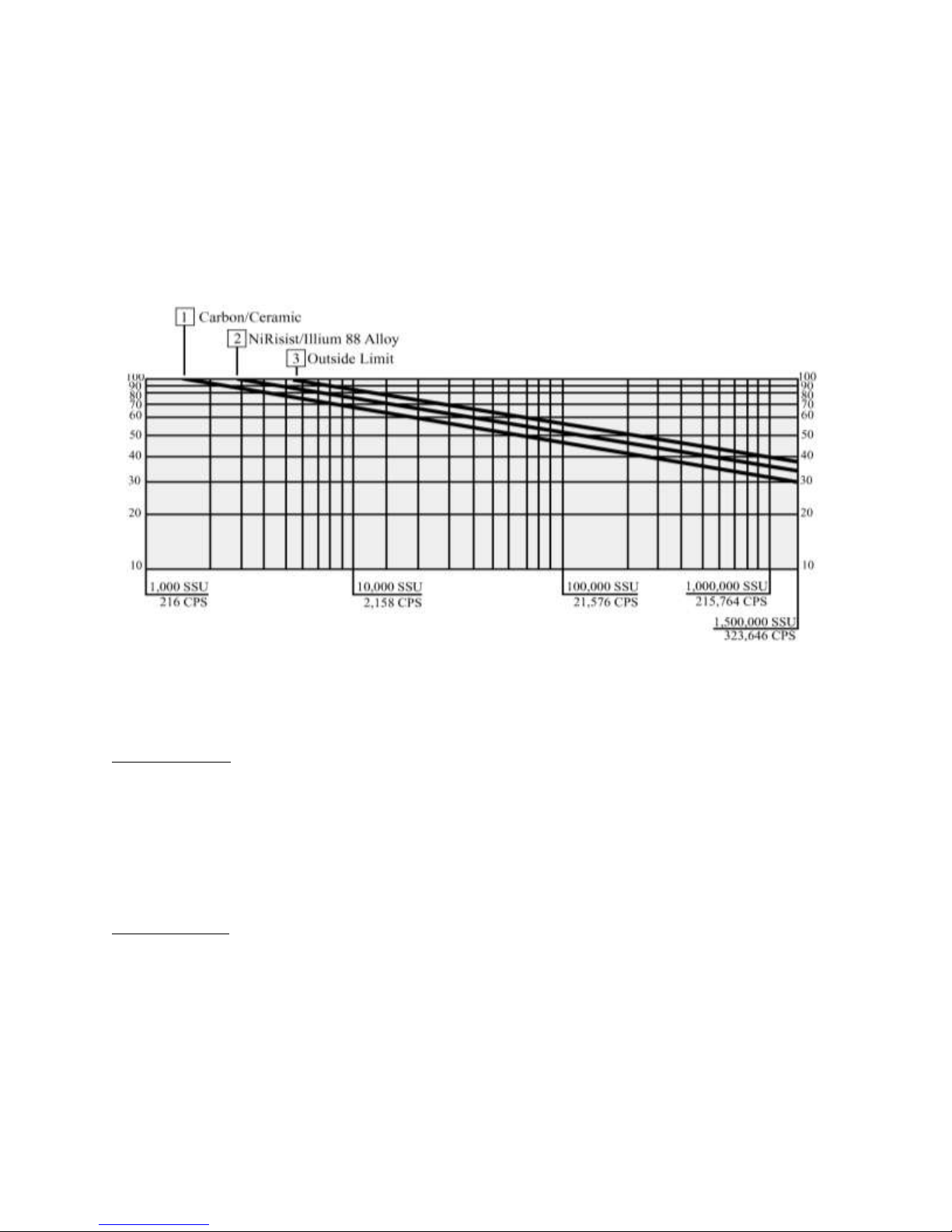
K) Bearing Load
The product viscosity will have a direct relationship on the flow rate of the system. The
following chart is a flow meter selection guide based on the relationship of viscosity and
flow rate. The bearing material is illustrated according to maximum bearing load allowable.
In the following flow chart, please choose the system flow rate and the product viscosity.
Then select the proper bearing sleeve material to identify the flow limitations of the flow
meter. If the system flow rate and viscosity do not meet your requirements, choose the next
size of flow meter or reduce the flow rate.
SYSTEM DESIGN
Meter Selection
The flow meter must be carefully chosen from the Meter Selection factors in the Engineering
Manual. The meter must be selected based on the operating system and product characteristics.
System variables include flow rate, temperature and pressure. The product characteristics
include the material compatibility, lubricity, viscosity, suspensions, pH, and whether the product
can congeal, crystallize or leave a dry film. Failure to select the correct flow meter may result in
system failure or serious injury.
Air Elimination
In any system that the tank may be completely drained or multiple products manifold into one
metering system, the possibility of air being present increases. The solution is an air or vapor
eliminator located before the flow meter to vent the air or vapor from the system before it can be
measured. Air or vapor elimination is required for all weights and measures regulatory
approvals in custody transfer applications.
- 10 -

Control Valves
Safety and isolation valves should be used throughout the metering system. In any pumping
system where there is one (1) pump and multiple flow meters, a digital or hydro-mechanical
Rate-of-Flow control valve must be used at each flow meter to prevent over speeding of the flow
meters.
Best Plumbing Configuration
1). Flow meter must have secure mounting to a riser stand or the foundation.
2). The inlet and outlet piping must be securely supported, in a manner of not to allow pipe
stress on flow meter.
3). System should be designed to keep the flow meter full of liquid at all times.
4). System piping should have the same full pipe diameter or larger as the flow meter,
throughout the metering system to allow for minimal pressure loss.
5). The pipe should be laid out as straight as possible to reduce pressure loss from flow
restriction.
6). The meter and piping must be installed in such as way as to avoid accidental draining of the
meter. Meter inlet and outlet should be lower than the associated system plumbing (sump
position).
7). It is not necessary for the air eliminator to be installed bolted directly to the meter. It can be
installed upstream from the meter. For effective operation of the air eliminator, it should be
mounted between the meter and any valves, tees or any other potential places where air may
enter the system.
8). The metering system should include a means for calibration.
Protection From Debris
On new installations, care must be taken to protect the meter from damage during start-up. It is
recommended to put a strainer before the meter. Damage may result from the passage through
the meter of dirt, sand, welding slag or spatter, thread cuttings, rust, etc. The insertion of a spool
(a flanged length of pipe equal in length to the meter and accessories attached to the meter) in
place of the meter until the system is flushed, temporarily bypassing the plumbing around the
meter, will also protect the meter from debris. Once the system has run “clean” for a period of
time the meter may be reinstalled or protective devices removed.
Thermal Expansion
As with most liquids, they will expand and contract with temperature. In any system where there
is a chance for liquid to be captured between closed valves without relief, thermal expansion will
likely occur and create dangerously high pressures within the system. Care should be taken in
designing the system in which thermal shock may occur by implementing Pressure Relief Valves
or Thermal Expansion Joints in the system design.
When product is trapped within the system, the pressure will increase by 126 PSI (8.69 BAR) for
every one (1) temperature degree increase.
- 11 -

Thermal Shock
The system operating temperature will expand or contract the metals within the flow meter. For systems
that have sudden or immediate temperature increases of 68 F (20 C) degrees or more, will require
clearance rotors. Clearance rotors will be necessary to eliminate the effect of immediate
expansion of the rotors vs. meter body, caused by thermal shock.
Hydraulic Shock (Water Hammer)
Hydraulic shock is a rise in pressure, which happens when an operating system has immediate
change in direction of flow such as a fast valve closure at a high operating flow rate. Hydraulic
shock can damage any item in the way of the product flow such as internal parts of the meter,
valves, and pump. System design and improper operating procedures will elevate this problem.
The use of 2-stage preset control valves or surge suppressing bladders or risers will help reduce
or eliminate this problem.
To compute the shock pressure when a valve is closed quickly (recommended to be less than 6
PSI):
Shock Pressure (PSI) = 63 x Velocity (FPS)
In order to eliminate hydraulic shock, you need to slow down the valve closure rate. The time
required to close the valve so that the line pressure will not exceed the normal pressure at no
flow is:
Time (seconds) = 0.027 x L x V
N – F
V = Velocity in Feet/Seconds
L = Length of pipe before the valve in feet
N = Line pressure at no flow
F = Line pressure at full flow
Products that Dry/Congeal/Crystallize
There are many liquids that crystallize, harden and/or solidify on contact with air or with an
increase in temperature. A proper system design and a good understanding of the product being
measured will help to avoid the possibility of air entering into the system and the product being
affected.
Calibration
The meter shall be tested and calibrated with the product it is intended to measure when installed.
Total Control Systems shall not be responsible for loss of product or any damages resulting from
the end user’s failure to test this meter to insure proper calibration. Every 700 series meter is
tested and calibrated at the factory to prove it is calibratable in your system. It is the owner’s
responsibility to report this device to the local Weights and Measures officials for their
inspection before the meter is put to use. Refer to the Material Safety Data Sheet of the
calibration fluid used in testing on pages 43 to 46 for more information.
- 12 -
- 13 -
- 14 -
 Loading...