

Total Controls QuickPanel jr. QPKSxDN0000 Series, QuickPanel jr. QPKCxDE0000 Series Installation Instructions Manual
QuickPanel jr.
p
QPKSxDN0000, QPKCxDE0000
GFK-2246
January 20, 2003
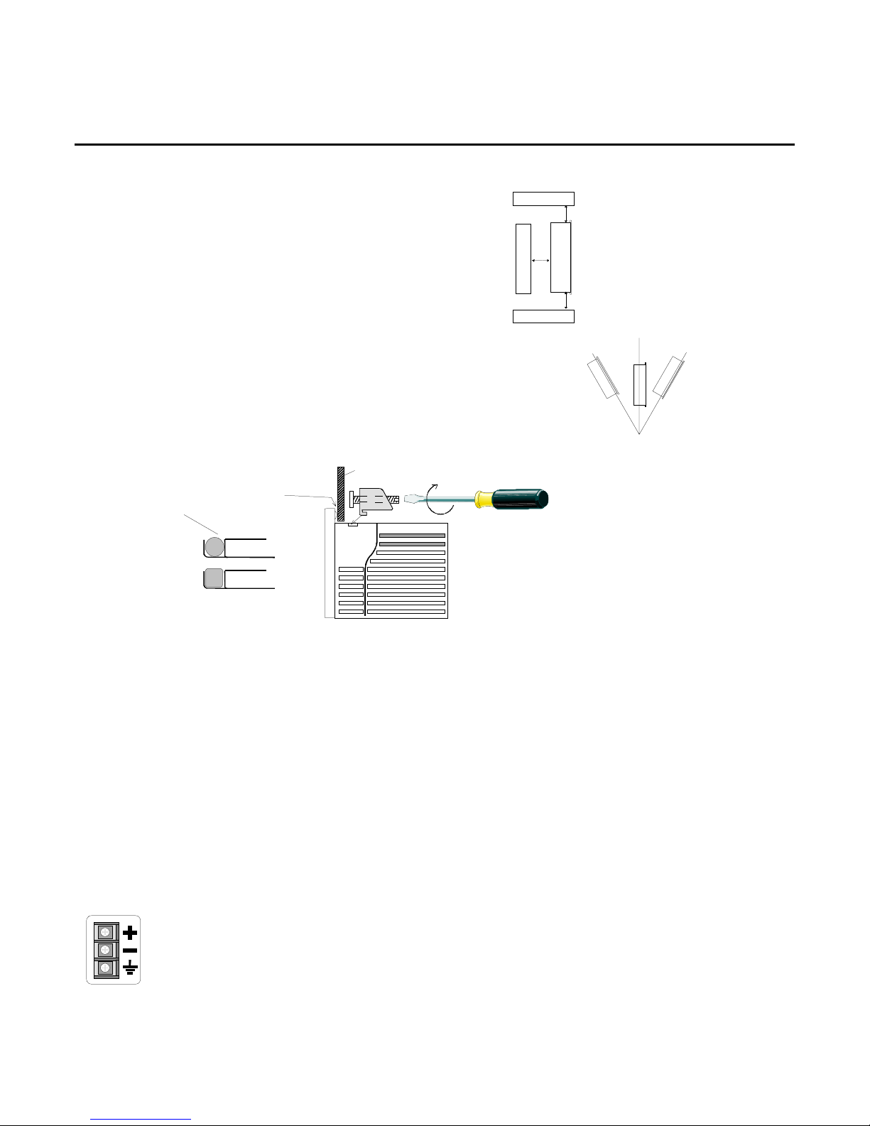
The panel clamps are packed in the carton.
Note:
For easier maintenance and proper ventilation, ensure the display is
mounted away from all surrounding objects.
Precautions
•
When installing the display on a slanted panel, the slope of the panel should be within 30°
from the vertical position. If the slope is greater than 30°, provide fan cooling.
•
Ensure heat from other equipment does not interfere with the display.
•
For proper ventilation, provide 4" of clearance around the Quickpanel.
•
Ground the display to earth ground.
•
Panel thickness = (1.6mm to 5mm) 0.063in to 0.197in
PANEL
1. Install the gasket in the slot in
the faceplate.
Torque = 0.5~0.6Nm
O-RING
or
FLAT
FRONT
2. Insert the display through the panel
opening. Insert the panel clamps into
the slots in the display body. Turn
screw clockwise to tighten.
Installation Instructions
SIDE
4in(100mm)
4in(100mm)
4in(100mm)
30° 30°
Units Marked UL and c-UL
Use No. 14 to 18 AWG, solid or stranded copper conductors and note the following precautions.
Suitable for use in Class I, Division 2, Groups A, B, C and D hazardous locations, or nonhazardous locations only. Power,
Input and Output (I/O) wiring must be in accordance with Class I, Division 2 wiring methods, Article 501-4(b) of the
National Electrical Code, NFPA 70 or as specified in Section 18-152 of the Canadian Electrical Code for installations within
Canada and in accordance with the authority having jurisdiction.
WARNING
WARNING
known to be nonhazardous.
WARNING
: Explosion hazard - substitution of components may impair suitability for Class I, Division 2.
: Explosion hazard - do not disconnect equipment unless power has been switched off or the area is
: Explosion hazard - when in hazardous locations, turn off power before replacing or wiring modules.
DC Power
DC24V
22W
QPK-
1. MAKE SURE THE POWER IS OFF.
2. Remove the protective cover on the DC terminal strip.
3. Remove 1/4" of insulation from the supply wires and insert them
under the terminal clanm
4. Tighten the clamp screws to secure the wires.
5. Replace the protective cover.
s.
2 QuickPanel jr. Installation Instructions
GFK-2246
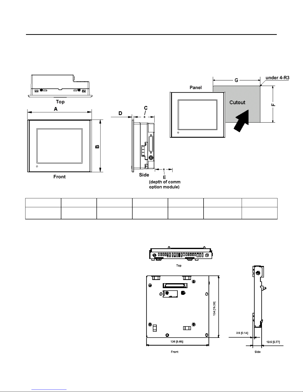
QuickPanel jr. 6" Displays (QPKSxDN0000, QPKCxDE0000)
Dim A Dim B Dim C Dim D Dim E Dim F Dim G
6.73
(171mm)
QPKSxDN0000 and QPKCxDE0000 require converter QPJ-PSM-201 when using a comm. option module.
Note:
Option modules:
QPJ-ABD-201 A-B DH Plus
QPJ-ABR-201 A-B Remote I/O
QPJ-MBP-201 Modbus Plus
QPJ-GEG-201 GE Genius
QPJ-DVN-202 DeviceNet
QPJ-IBS-201 Interbus-S
QPJ-PBS-201 Profibus
QPJ-COS-201 CANopen
5.43
(138mm)
2.16
(55mm)
0.2
(5mm)
1
(25mm)
4.86 (+0.04)
(123.5+1mm)
6.14 (+0.04)
(156mm +1mm)
 Loading...