

Page 1

Bus Conversion Unit
10.5” & 12.1” QuickPanel Ethernet Series
Installation Guide
Bus Conversion Installation Guide
GFK-2073
Page 2

The following are trademarks of Total Control Products, Inc.: QUICKPANELÔ and
QUICKPANEL jr.Ô
Information in this document is subject to change without notice and does not represent a commitment
on the part of Total Control Products, Inc. The software described in this document is provided under a
license agreement. The software may be used or copied only under the terms of the agreement. Only
one copy of the software may be made for a backup.
Total Control Products, Inc. makes no warranty, either expressed or implied, including but not limited
to any implied warranties of merchantability or fitness for a particular purpose, regarding these
materials and makes such materials available solely on an "as-is" basis.
In no event shall Total Control Products, Inc. be liable to anyone for special, collateral, incidental, or
consequential damages in connection with or arising out of purchase or use of these materials. The sole
and exclusive liability to Total Control Products, Inc., regardless of the form of action, shall not exceed
the purchase price of the materials described herein.
No part of this manual may be reproduced or transmitted in any form or by any means, electronic or
mechanical, including photocopying, recording, or information storage and retrieval systems, for any
purpose other than the purchaser's personal use, without the express written permission of Total
Control Products, Inc.
Copyright 1995, Total Control Products, Inc. All rights reserved.
2700 Oxford Tower, 10235-101 Street, Edmonton, Alberta T5J 3G1, CANADA
Total Control Products, Inc.
Phone (780) 420-2000, Fax (780) 420-2049
Page 3

-1-
Bus Conversion Unit
(QPI-PSL-201)
(for 10.5" & 12.1" QP-Ethernet Series Units)
Thank you for purchasing Total Control Products' Bus Conversion Unit
(QPI-PSL-201), hereafter referred to as the "Unit". This Unit allows the attachment
of QPI-xxx-20x series expansion units to 10.5" and 12.1" QP-Ethernet Series units.
This manual provides an overview of this Unit, as well as procedures to follow when
installing it in the User's system. Be sure to read all this important information carefully
prior to using this Unit.
This product is CE marked and UL/c-UL(CSA) compliant. Therefore, be aware
that when it is used in combination with a product that is not CE marked and UL/
c-UL(CSA) compliant, this product will lose its conformance with these standards.
Page 4
-2-
Indicates situations where slight bodily injury or machine damage can occur.
Indicates situations where severe bodily injury, death
or major machine damage can occur.
This guide includes information that must be followed to ensure the correct and safe use
of this product. Be sure to read both this guide and any related manuals to thoroughly
understand the correct operation and functions of both the Bus Conversion Unit and the
10.5" and 12.1" QP-Ethernet Series units.
Usage of Safety Icons
Throughout this manual the following icons are shown near procedures requiring special attention to safety. The information given below these icons contains essential safety
information.
The following examples explain the meaning of each safety icon:
Safety Precautions
CAUTION
WARNING
To prevent this unit from malfunctioning :
• Be sure the Unit is operated in an environment that is within the unit's designated temperature range.
• Do not operate or store this unit in an environment where it will be exposed to
high temperatures.
• Do not operate or store this unit in an environment where it will be exposed to
direct sunlight or excessive amounts of dust.
• Since this unit is a precision instrument, do not install it where strong impacts or
vibration will occur.
• Do not operate or store this unit in an environment where it may be exposed to
chemical vapors or fumes.
• When attaching this unit to a 10.5" or 12.1" QP-Ethernet Series unit, make
sure that the QP-Ethernet's power cord is not connected to the main power
(constant), to prevent an electric shock.
• Do not modify this Unit in any way, since an electric shock or fire may occur.
• Do not use this Unit in areas where flammable gas is present, since an explosion may occur.
• Do not allow water, liquid or metallic objects to enter into the Unit, since they can
cause either a malfunction or an electric shock.
WARNINGS
Page 5

-3-
The QPI-PSL-201 (Model #2980020-02) is a UL/c-UL listed product. (UL file No.E182139)
This unit conforms as a product to the following standards:
zz
zz
z
UL508
Industrial Control Equipment
zz
zz
z
UL1604
Electrical Equipment for use in Class I and II, Division 2, and Class III Hazardous
(Classified) Locations.
zz
zz
z CAN/CSA-C22.2, Nos. 142, and 213-M1987
Standard for Safety of Information Technology Equipment, including Electrical Business Equipment
QPI-PSL-201 (UL Registration Model #2980020-02)
UL1604 Conditions of Acceptability and Handling Cautions:
1. Power, input and output (I/O) wiring must be in accordance with Class I, Division
2 wiring methods - Article 501- 4(b) of the National Electrical Code, NFPA 70
within the United States, and in accordance with Section 18-152 of the Canadian
Electrical Code for units installed within Canada.
2. Suitable for use in Class I, Division 2, Groups A, B, C and D, Hazardous Locations.
3. WARNING: Explosion hazard - substitution of components may impair suitability
for Class I, Division 2.
4. WARNING: Explosion hazard - when in hazardous locations, turn power OFF
before replacing or wiring modules.
5. WARNING: Explosion hazard - do not disconnect equipment unless power has
been switched OFF, or the area is known to be non-hazardous.
The QPI-PSL-201 is a CE marked
*1
product that conforms to EMC directives
EN55011 Class A and EN61000-6-2.
*1 For detailed CE marking information, please contact your local distributor.
UL/c-UL (CSA) Application Notes
CE Marking Notes
Page 6
-4-
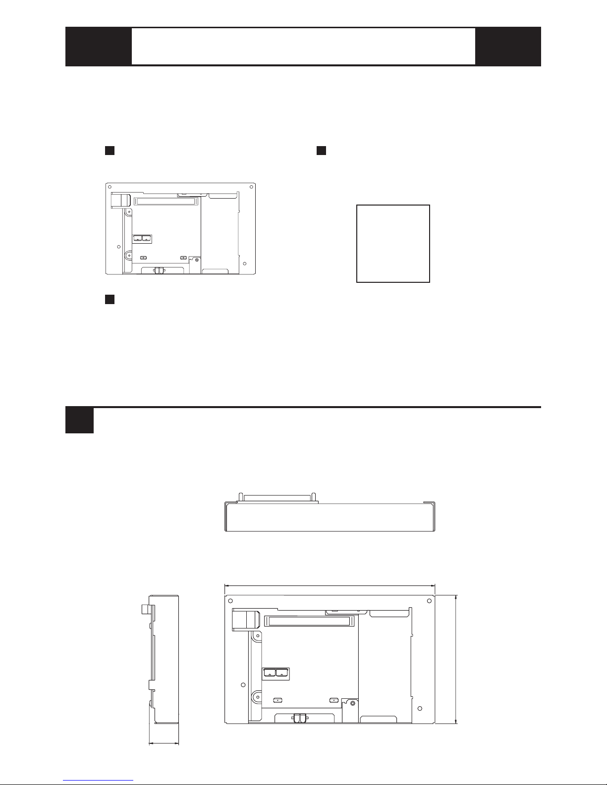
The following items are included in the Unit's package. Prior to using the Unit, be sure
to confirm that all the items shown below are present.
This unit has been carefully packed with special attention to quality. However, should
you find anything damaged or missing, please contact your local distributor
immediately.
Package Contents
Bus Conversion Unit
( QPI-PSL-201)
Bus Conversion Unit
Installation Guide ( 1 )
( this document )
Bus Conversion
Unit
Installation
Guide
Attachment Screws (4 )
Top
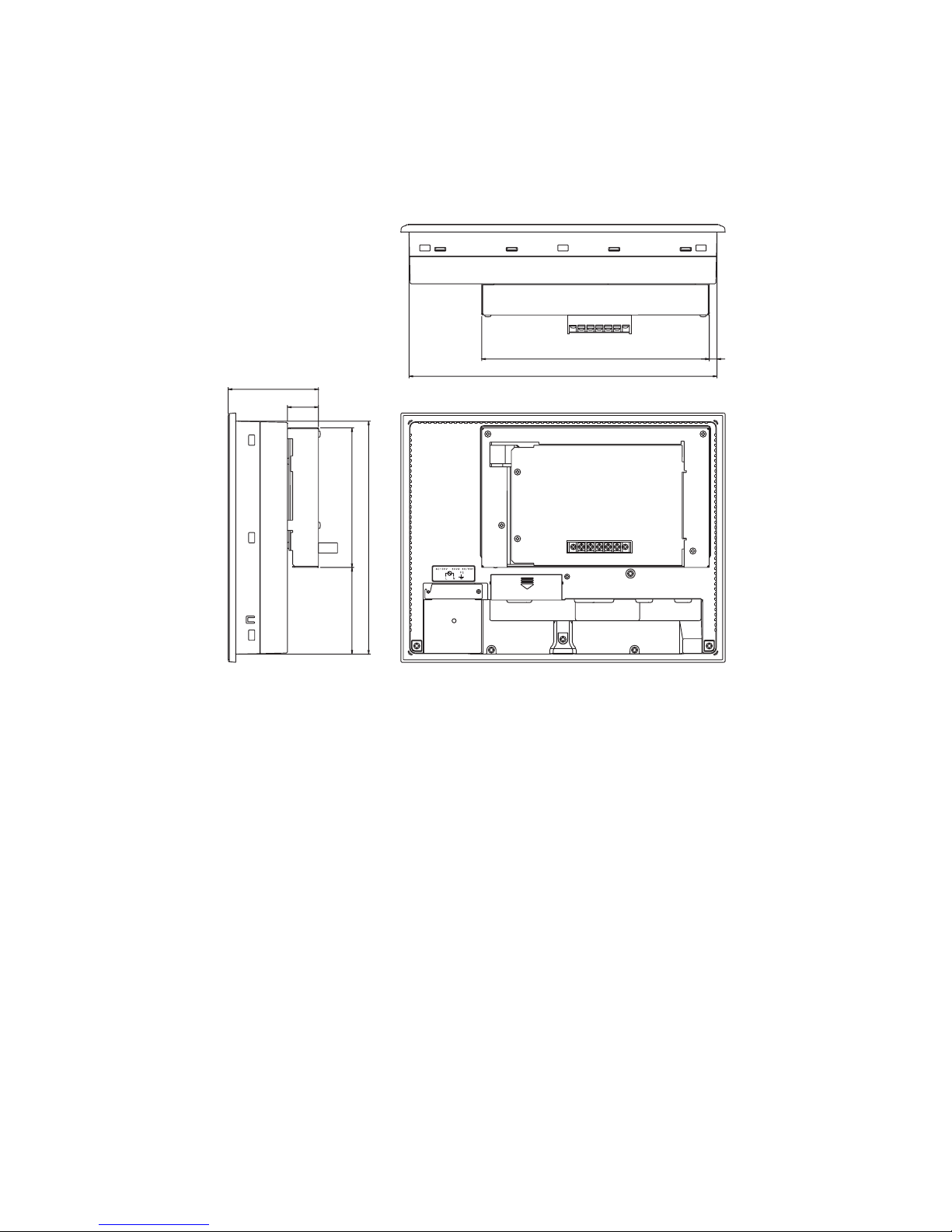
The Unit's external dimensions are given below.
1 Dimensions
Unit: mm [in.]
Front
Right Side
32 [1.26]
223 [8.78]
136 [5.35]
Page 7
-5-
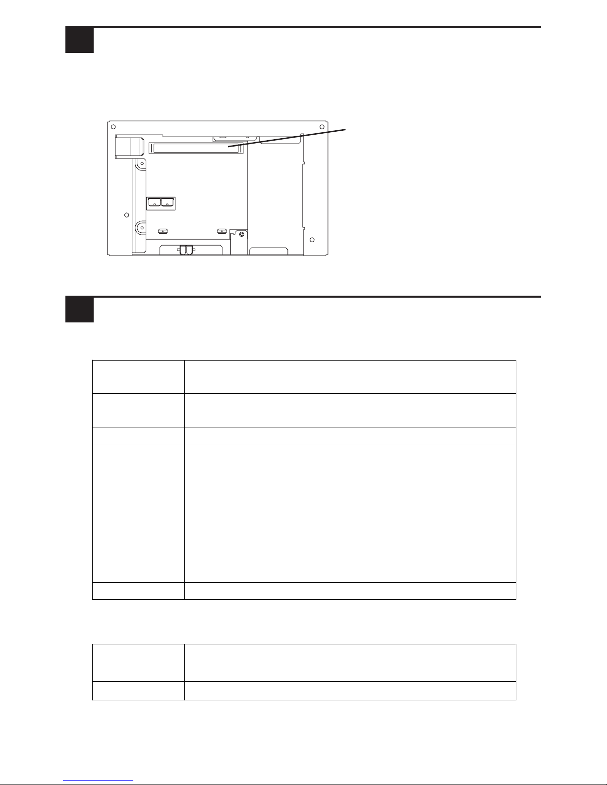
The figures below show the Bus Conversion Unit and an expansion unit attached to a
10.5" or 12.1" QP-Ethernet Series unit.
Unit: mm [in.]
Rear
Top
Left Side
89 [3.50]
31 [1.26]
136 [5.35]85 [3.35]
(227 [8.94])
223 [8.78]
(301 [11.85])
8 [0.31]
Page 8
-6-
Environmental
Structural
The Unit's part name and its function are explained below.
2 Part Name and Function
3 General Specifications
Expansion Bus Connector
Used to connect QPI-xxx-20x
series expansion units.
Operating
Temperature
0
o
C to 50 oC
Storage
Temperature
-20
o
C to +60 oC
Humidity 10%RH to 90%RH ( no condensation)
Vibration based on JIS B 3501, IEC61131-2
Resistance (i ntermit tent vi bration)
10Hz to 57Hz 0.075mm
57Hz to 150Hz 9.8m / s
2
(continuous vibration)
10Hz to 57Hz 0.035mm
57Hz to 150Hz 4.9m / s
2
X, Y, and Z di rections for 10 tim es each (80m in.)
Corr osi ve G as Free of corrosi ve gas
External
Dimensions
W223 [8. 78] x H 136 [5.35] x D32 [ 1.26] mm [in.]
(Main unit only - excludi ng pr ojections)
Weight approx. 500g ( 1. 10lb.)
Page 9
-7-
4 Installation
Use the following procedures to install the Bus Conversion Unit in a QP-Ethernet
Series unit.
1. Disconnect the QP-Ethernet Series
power cord from the power supply.
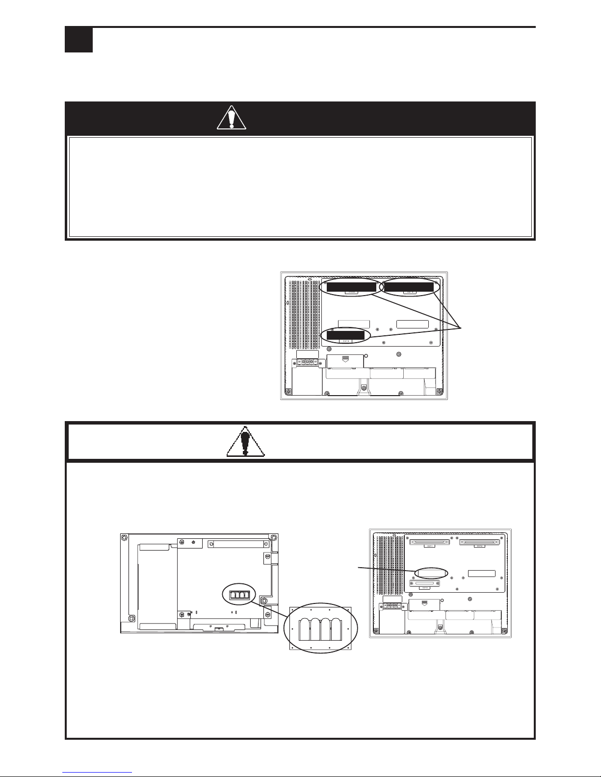
2. Remove the three (3) Expansion
Slot covers on the rear of the
QP-Ethernet Series unit.
• Do not remove this Unit from the QP-Ethernet unless absolutely necessary.
Excessive attachment and removal can lead to the Unit's premature
breakdown or malfunction.
Rear of Bus Conversion Unit
Rear of QP
Expansion
Slot covers
Copper
spring
contact
location
Copper Spring
Prior to installing this Unit:
• When attaching this unit to the QP-Ethernet Series units, make sure that
the QP-Ethernet's power cord is not plugged in to the main power (constant),
to prevent an electric shock.
• Be careful not to touch the surface of this unit's printed circuit board and be
sure to wear cotton gloves.
WARNINGS
CAUTIONS
• Do not touch the "copper spring" or the copper spring's contact. Be sure to wear
gloves when installing this unit.
Page 10
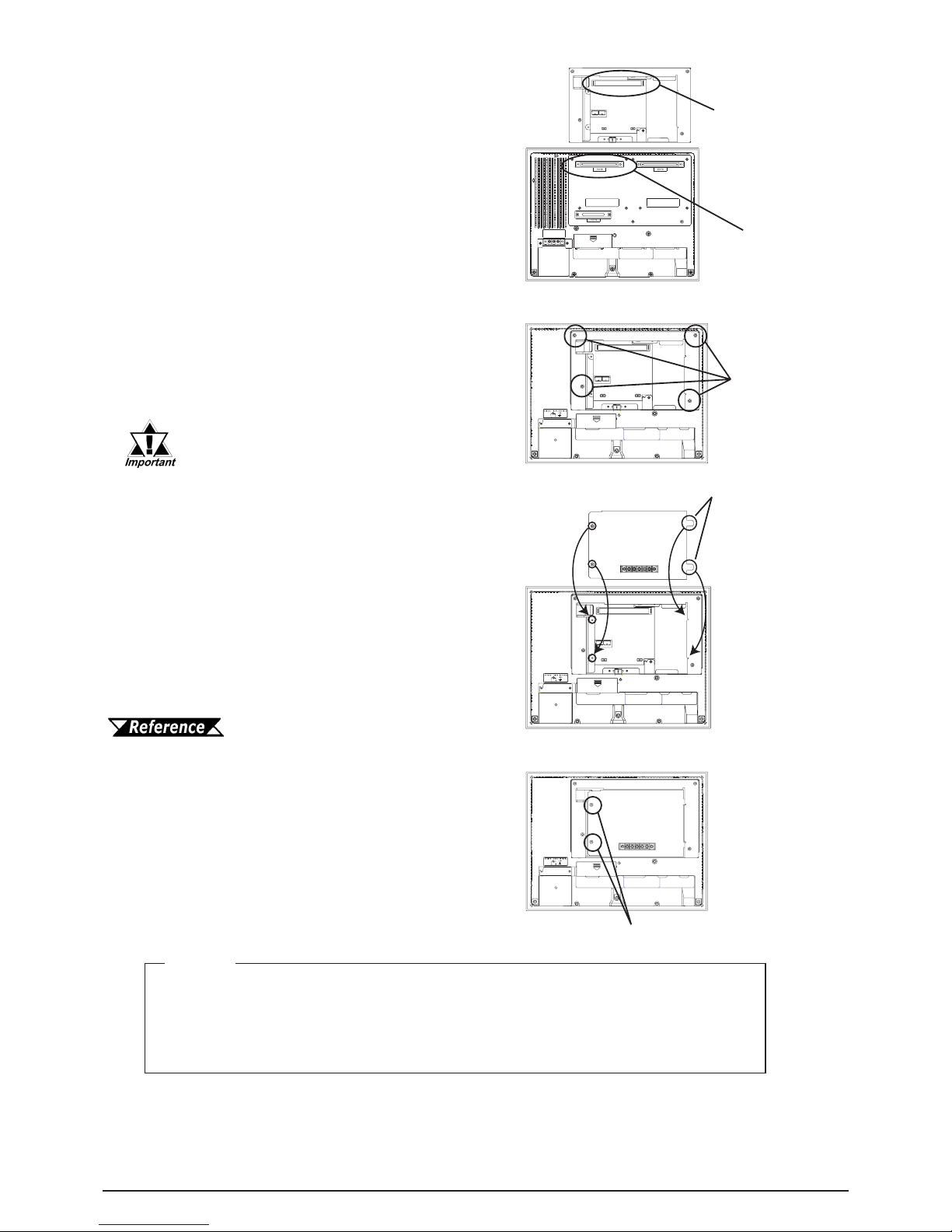
3. Align the Expansion Bus Connector over
the QP-Ethernet Series unit's Rear Face
Expansion Unit I/F. Then, press the Unit
down so that the two unit's connect.
5. Insert the expansion unit Attachment Tabs
into the QP-Ethernet unit Attachment
Slots. Be sure to install the expansion unit
so that its smooth metal surface faces outward.
4. After the two connectors are securely attached, insert the four (4) attachment
screws into the four (4) attachment screw
holes and tighten the screws. Be sure that
no gaps remain between the QP-Ethernet
Series unit and the Unit.
6. Attach the expansion unit to the Bus Conversion unit and tighten the two (2) expansion unit attachment screws (included
with unit).
Attachment
Screw Holes
Attachment Screws
Attachment Tabs
Expansion Unit Users Manual
A torque of only 0.5 to 0.6 N•m is
required to tighten an attachment
screw. Be careful not to use too
much force, since it may damage
the QP-Ethernet unit.
Expansion Bus
Connector
Expansion
Unit I/F
Note
Please be aware that Total Control Products shall not be held liable
by the user for any damages, losses, or third party claims arising from
the uses of this product.
 Loading...