

Page 1

MP/8 V.34
TOTAL CONTROL
Getting Started
1996 U.S. Robotics Access Corporation
1800 West Central Road
Mount. Prospect, IL 60056
All Rights Reserved
Page 2

U.S. Robotics and the U.S. Robotics logo are registered trademarks of U.S. Robotics
Access Corporation. Total Control is a trademark of U.S. Robotics Access
Corporation. Any trademarks, tradenames, service marks, or service names owned or
registered by any other company and used in these release notes are the property of
their respective companies.
Page 3

U.S. Robotics, the U.S. Robotics logo, and MP/8 V.34 are
registered trademarks of U.S. Robotics Access Corporation.
V.Fast Class and V.FC are trademarks of Rockwell
International. Any trademarks, trade names, service marks or
service names owned or registered by any other company and
used in this manual are the property of their respective
companies.
1996 U.S. Robotics Access Corp.
8100 N. McCormick Blvd.
Skokie, IL 60076-2999 USA
Page 4

Table of Contents
About This Manual iv
Chapter 1 Introduction 1-1
About the MP/8 V.34 modems 1-2
Status Indicators 1-2
Features 1-4
Modem Compatibility 1-5
Chapter 2 Installing the MP/8 V. 34 modem 2-1
Requirements 2-1
Package Contents 2-1
Installing the MP/8 V.34 2-2
Setting the DIP Switches 2-4
Cabling 2-6
Chapter 3 Configuring the Modems 3-1
Templates 3-1
Accessing the Modems 3-7
Changing the Default Template 3-7
Custom Configurations 3-8
Using S-Registers 3-9
Appendix A Notices A-1
Notices A-1
Index 1
Page 5

About This Manual
This manual explains how to set up and start using your Total
Control MP/8 V34.
Refer to the V.Everything Command Reference manual, also
included with the MP/8 V.34, for thorough explanation of the
complete set of commands.
Page 6
Chapter 1
Introduction
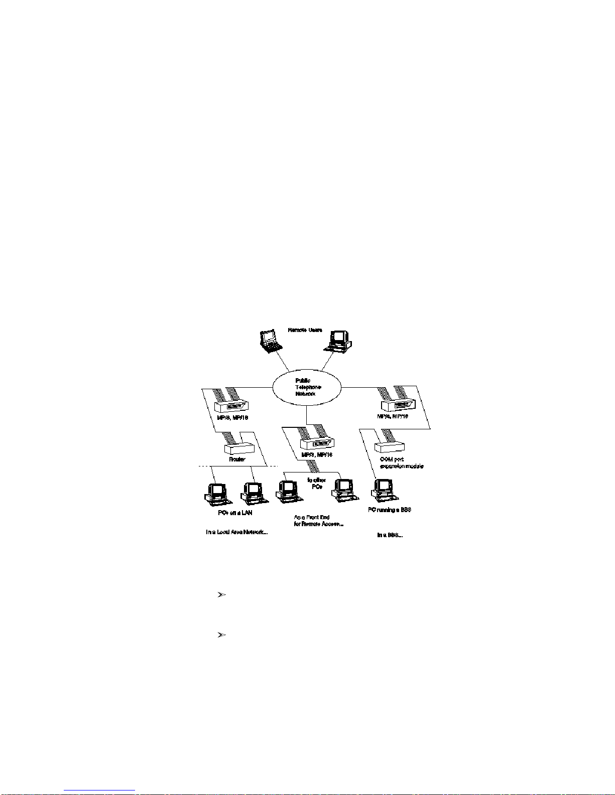
The Total Control MP/8 V.34 modem integrates eight data
channels, which utilize the latest modem technology into one
compact unit. MP/8 V.34 is a versatile unit that fits into
numerous system setups. Here are a few examples:
In a Local Area Network... the MP can be interfaced to a
terminal server or a router, allowing multiple users
remote access to your network.
As a Front End for Remote Access... the MP may front-end
a rack of PCs running remote access operations.
Page 7
1-2 MP/8 V.34: Getting Started
In a BBS... the MP can be hooked up to a computer
running a BBS via a COM port expansion module. All
the calls coming in to the BBS will come through a
single unit.
About the MP/8 V.34 modems
This section briefly describes the functions of the Status
Indicators, the Telco jacks, and the RS-232 jacks.
Status Indicators
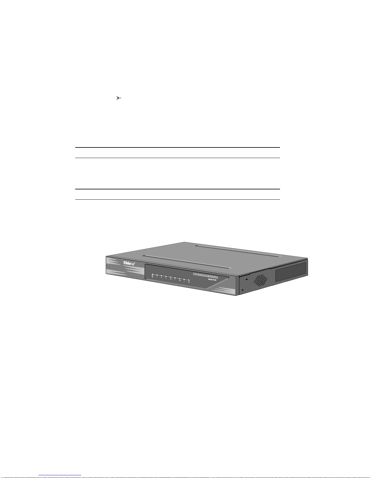
The MP/8 V.34 modems display their status using
light-emitting diodes (LEDs) that are visible from the front. The
MP/8 V.34 modem has nine LEDs on its front panel.
The Run/Fail LED indicates whether the unit is operating. The
other LEDs are numbered 1–8, each number corresponding to
one channel. The colors indicate the status of each channel as
follows:
Table 1-1. Meanings of the Indicator Lights.
Figure 1-1. Front View of the MP/8 V.34.
Page 8
Appearance Meaning
Off Idle, ready to make or receive calls
Amber blink
(8 per second)
Amber blink
(1 per second)
Green blink
(1 per second)
Green Connection OK
Amber Negotiating (training) with a remote analog
Red U interface not found
Red blink
(1 per second)
Looking for U interface
Looking for S/T interface
U and S/T interfaces found; waiting for line to
become active
device
Incorrect SPID
Telco Jacks
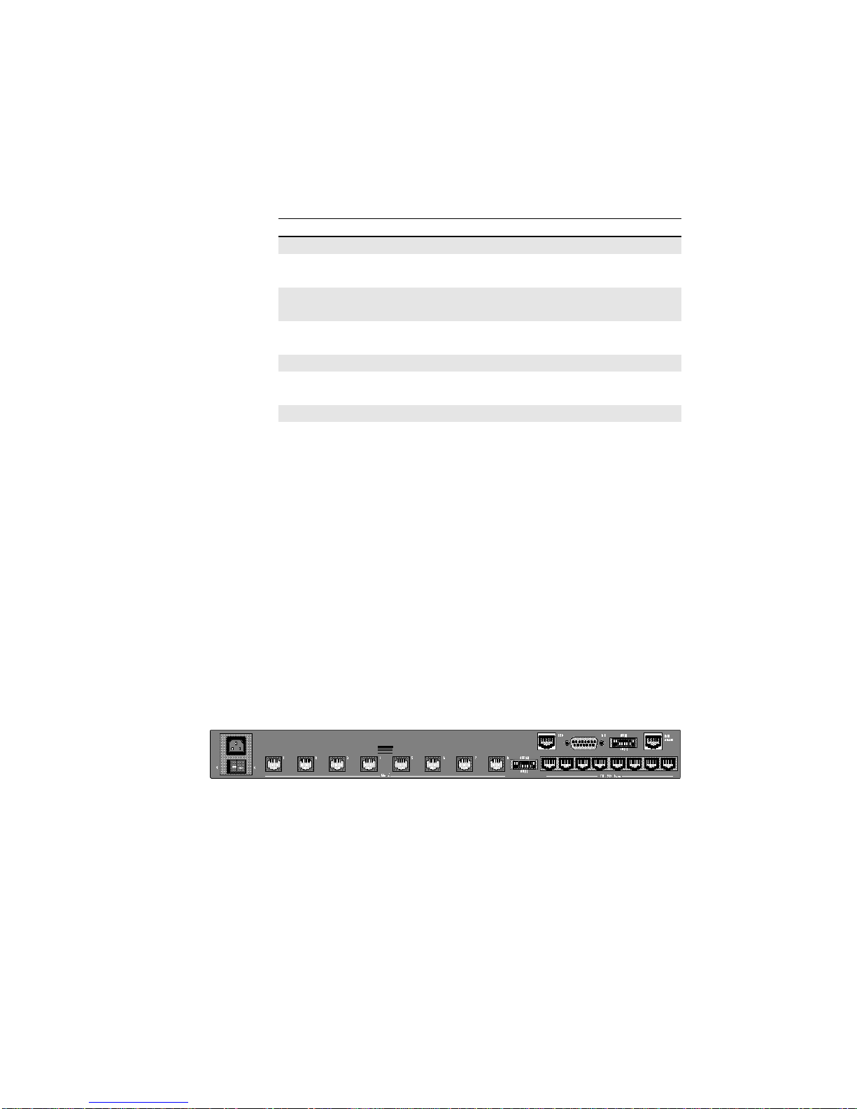
The Telco jacks located on the back panel provide access to the
phone lines through an RJ-11 telephone cable. They are labeled
1-8, according to the modem each corresponds to.
Introduction 1-3
RS-232 Jacks
RS-232 jacks allow the modems to interface with computers.
These are also labeled 1–8 according to the modem each
corresponds to. The RJ-45 connectors on the unit meet EIA/TIA
561 standards.
Telco jacks
Figure 1-2. Back view of the MP/8 V.34.
RS-232 jacks
Page 9

1-4 MP/8 V.34: Getting Started
Features
High-Speed Connections
With the V.34 Everything and the V.Fast Class modulation
scheme, two modems can connect at rates up to 31.2 Kbps and
33.6 Kbps when connecting with other U.S. Robotics modems
with 33.6 Kbps capability. V.32 bis modems connect at rates up
to 14.4K bps.
Custom Configurations
You can create custom configurations to use as default settings
and store them in Non-Volatile Random Access Memory
(NVRAM) . Each time the unit is powered on or reset, it
operates at the settings you've specified. See Chapter 3,
Appendix B, and Appendix C.
Software Upgrades
U.S. Robotics high-speed modems are equipped with Flash
ROM, making them software upgradable. Through the U.S.
Robotics BBS, there is easy access to software which can bring
your modems up to date on the latest advances in data
communication technology. See Appendix H.
Fax Capability
You can use your modem with Class 1 or Class 2.0 facsimile
software to exchange faxes with millions of Group III fax
machines worldwide. See Appendix F.
Dial Security
With Dial Security, you will be able to prevent unauthorized
access to the system with the use of Autopass, Prompting, and
Dialback. See Appendix D for more information.
Page 10

HELP Screens
The modem displays screens that summarize the command sets,
Dial command options, and S-Register functions. See Chapter
3.
Modem Compatibility
Total Control MP modems adhere to the following modulation
schemes and standards, ensuring com patibility with a wide
base of installed modems.
Note: The International Telecommunication Union (ITU-T) was
formerly the International Telegraph and Telephone Consul tative Committee (CCITT).
ITU-T V.34 28.8K/26.4K/24K/21.6K/19.2K/16.8K/
14.4K/12K/9600/7200/4800/2400 bps
(V.34 only)
V.FC 28.8K/26.4K/24K/21.6K/19.2K/16.8K/
14.4K bps (V.34 only)
Introduction 1-5
V.32 terbo 21.6K/19.2K/16.8K/14.4K/12K/9600/
7200/4800 bps
ITU-T V.32 bis 14.4K/12K/9600/7200/4800 bps
ITU-T V.32 9600/4800 bps
ITU-T V.22 bis 2400 bps
Bell 212A 1200 bps (also V.22)
ITU-T V.23 1200 bps with 75 bps back channel (some U.K.
and European phone systems)
ITU-T V.25 Answer sequence for calls originating outside
the U.S. and Canada
Bell 103 300 bps (ITU-T V.21 optional)
ITU-T V.42 LAPM error control, 1200 bps and higher
ITU-T V.42 bis Data compression, 1200 bps and higher
MNP Levels 2, 3, and 4 error control, level 5 data
compression, 1200 bps and higher
Page 11

1-6 MP/8 V.34: Getting Started
ITU-T V.54 Analog, digital, and remote digital loopback
testing
Page 12

Installing the MP/8 V. 34 modem
Requirements
A computer or terminal with a serial port that uses
standard EIA RS -232 signaling.
A serial cable with a male DB -25 connector on one end and
a connector that is appropriate for your computer’s serial
port on the other.
A Phillips screwdriver.
If you’re rack -mounting the MP/8 V.34 modem, screws that
are appropriate for your equipment rack.
Computers or terminals with up to eight serial ports that
use standard EIA RS -232 signaling.
Package Contents
Chapter 2
The package contains the following items:
♦ Total Control MP/8 V.34
♦ Power cable.
♦ RJ-11 telephone cables
♦ Rack mounting brackets and screws.
♦ Rubber feet.
♦ This manual.
♦ MP/8 V.34 Modems Command Reference manual.
Page 13

2-2 MP/8 V.34: Getting Started
Installing the MP/8 V.34
The Total Control MP is designed to be used either stand -alone
or mounted in a standard 19 -in. equipment rack. Follow the
instructions for the installation method that suits your needs.
Important!
♦ Do not block the vents on the right side of the unit.
♦ Keep the unit in a dry place at room temperature.
♦ If using the unit as a stand -alone, keep it on a flat surface.
This will leave room above and below for adequate
ventilation.
♦ When installing more than one chassis in an equipment
rack, leave room above and below them for adequate
ventilation.
Stand-Alone Installation
1 Find the rubber feet that are included with the package.
2 Turn the MP/8 V.34 over and attach a rubber foot in each
of the recesses in the four corners of unit.
3 Turn it back over and place it on the surface where it will be
used.
4 Go to Setting the DIP Switches.
Installing the Unit in a Rack
1 Find the mounting brackets (2) and the screws (4) that are
included with the package.
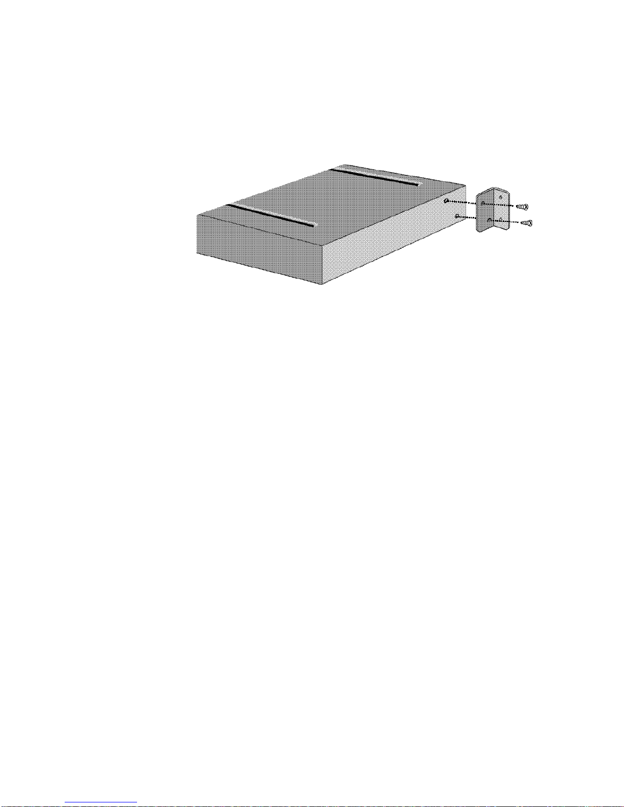
2 Line up the holes in the mounting bracket with the holes in
the MP/8 V.34, and then screw the bracket in place. See
Figure 2 -1.
Page 14
Installing the MP/8 V.34 2-3
Figure 2-1. Attaching a Mounting Bracket.
3 Installing the unit in the rack. Most racks come with the
necessary screws and nuts/anchors to install rack mounted
devices.
a First, gather four screws and enough nuts/anchors for
the screws.
b Then, holding the unit in the rack and supporting it
from underneath with one hand, insert screws in the
bottom left and bottom right slots and start threading
them. See Figure 2-2.
Page 15

2-4 MP/8 V.34: Getting Started
Figure 2-2. Mounting an MP/8 V.34 modem in a rack.
c Insert screws in the top left and top right slots and start
threading them.
d Beginning with the two bottom screws, tighten all four
until the unit is secure.
Setting the DIP Switches
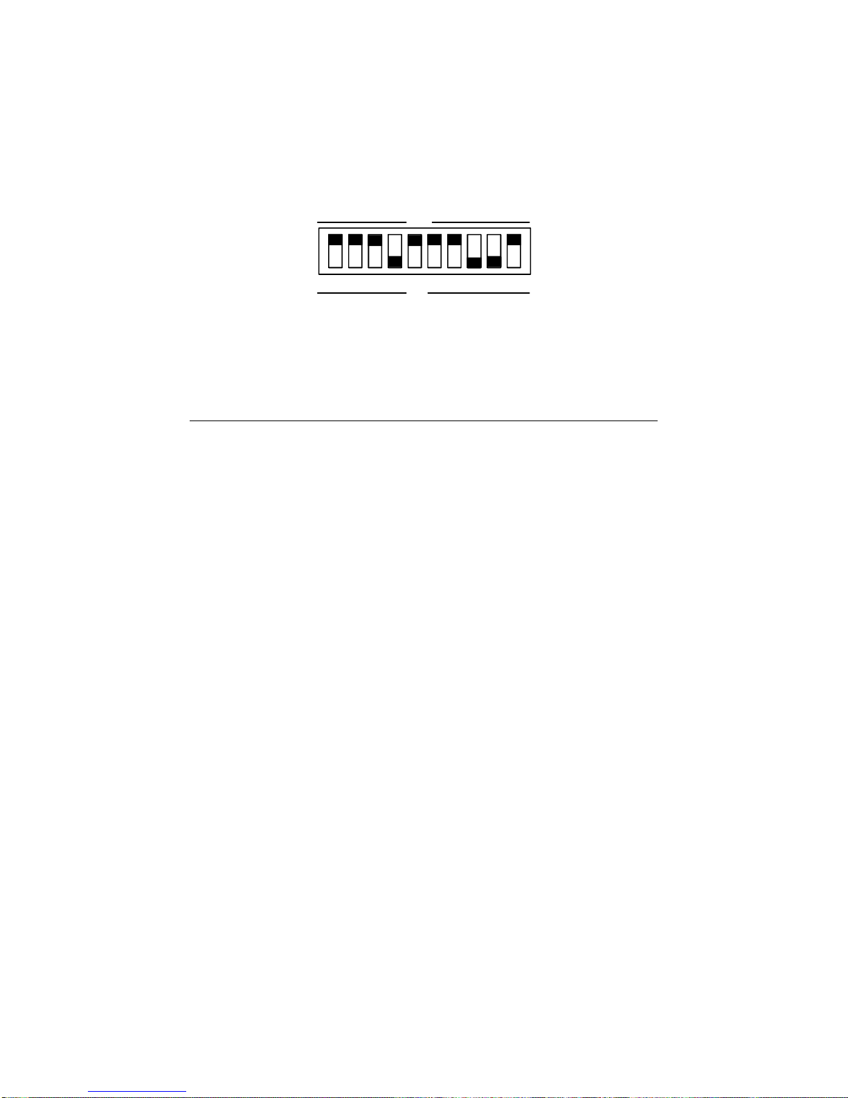
The DIP switches, located on the rear panel between the RS-232
and Telco ports, are for adapting the modem to your equipment
and system requirements. Each set of DIP switches controls 8
modems.
Figure 2.3 shows the DIP switches in their factory default
settings, which reflect typical system requirements such as:
Auto Answer enabled, no result codes, no Data Terminal Ready
or Carrier Detect override. See Table 2.1 for switch options to
decide if the factory settings need to be changed.
Page 16
Installing the MP/8 V.34 2-5
Figure 2.3—DIP Switch Factory Settings
Table 2.1—DIP Switch Functions
Factory
Switch Setting Function
1 OFF Data Terminal Ready Operations
OFF Normal DTR operations: computer must
provide DTR signal for modem to accept
commands; dropping DTR terminates a call
ON DTR always ON (Override)
2 OFF Verbal/Numeric Result Codes
OFF Verbal (word) results
ON Numeric results
3 OFF Result Code Display
OFF Result Codes suppressed
ON Result Codes displayed
4 ON Command Mode Local Echo
OFF Keyboard commands displayed
ON Echo suppressed
5 OFF Auto Answer
OFF Modem answers on first ring
ON Auto answer disabled
6 OFF Carrier Detect Operations
OFF Normal CD operations. Courier sends CD
signal when it connects with another modem,
drops CD on disconnect
ON CD always ON (Override)
7 OFF Auxiliary, DIP Switch 3 ON
Page 17

2-6 MP/8 V.34: Getting Started
OFF Result codes in Originate and Answer mode
ON Result codes in Answer mode disabled
8 ON AT Command Set Recognition
OFF Command recognition disabled (Dumb mode)
ON Enabled command set recognized
(Smart mode)
9 ON Escape Code (+++) Response
OFF Modem hangs up and returns to Command
mode
ON Modem maintains connection, returns to
Command mode
10 OFF Power-on/Reset Load Configuration Defaults
OFF Load from nonvolatile memory (NVRAM)
ON Load factory settings from read only memory
(ROM)
Cabling
1 Make sure that the unit’s power switch on the rear panel is
OFF.
2. Connect the modems to telephone lines. For each modem, plug
one end of an RJ-11 telephone cable into a Telco jack on the
rear panel of the unit. Plug the other end into a Telco jack.
Note: Do not confuse the RJ-11 and RJ-45 cables. They look
alike, but RJ-45 cables have more pins than RJ-11 cables: RJ11 cables have 4 pins where RJ-45 cables have 8 pins.
3. Connect the modems to terminals. The final step is to connect
the RS232 jacks to the computer or terminal equipment.
a. Connect one end of an RJ-45 cable into each of the RS-
232 jacks on rear panel of the unit.
b. Adapters—since the terminal’s RS-232 jack probably does
not fit with RJ-45 cables, this connection requires an
adapter. Depending on a system’s cabling needs, there
are cable kits available with either RJ-45 to DB-25 or RJ-
Page 18
Installing the MP/8 V.34 2-7
Power supply
45 to DB-9 adapters. Use these to plug the cable into the
terminals or network.
4. Plug the power cable into the power jack at the back of the
unit. Plug the cable into a standard 115-volt AC wall
socket.
5. Power on the unit. The Run/Fail LED should emit a green
light. If it does not indicate that the power is on, make sure
the power cable is attached tightly and the power switch is
on.
RJ11
cables
RJ45
cables
Page 19

Chapter 3
Configuring the Modems
Total Control MP modems are factory configured to run under
hardware flow control. Once the unit is set up, nothing else
needs to be done—the unit is all ready to operate. However,
the modems can be configured for specialized systems or
situations.
The modems use a superset of the standard AT command set
for dial-up modems. The commands control configuration
options as well as modem operations such as diagnostic testing.
Typically, you’ll need to directly command the modems only
for initial configuration, and to write that to Non-Volatile
Random Access Memory (NVRAM) with the commands. After
that, the modems will perform without operator intervention.
This chapter covers:
ROM Templates
Default—Hardware Flow Control Template
Low Performance Template
Software Flow Control Template
Accessing the Modems
Changing the Default Settings
Custom Settings in NVRAM
Using S-Registers
Templates
Read Only Memory (ROM) templates in the MP modems
contain settings for configuration commands and S-Registers
that control the way the modems operate. By tailoring any one
or more of these, the modems can be programmed to meet
specific communications needs.
Page 20

3-2 MP/8 V.34: Getting Started
Default—Hardware Flow Control Template—&F1
When the Total Control MP is first turned on, the modems
automatically load the hardware flow control template into
active RAM from Non-Volatile Random Access Memory
(NVRAM). The Hardware Flow Control template, though
stored in ROM, is also stored in NVRAM as the current settings.
Unless a modem is programmed for another template, it will
operate under this configuration.
In this configuration, the modems are set to operate with
hardware flow control, a fixed serial port rate using the highestlevel result codes.
The modem drops the Clear to Send (CTS) signal it has been
sending to the computer or terminal when the modem's buffer
nears 90% capacity. It starts sending CTS again when the buffer
is about half full.
Table 3.1 on the opposite page shows the configuration
command settings under the hardware flow control template.
Recommended Uses
This template is the most compatible and is recommended for
all systems and software that support Request to Send and
Clear to Send hardware signaling, and a fixed serial port rate to
provide flow control. It offers the greatest efficiency and
reliability. If your system requires software flow control, your
best bet is to use the Software Flow Control template described
next.
If your system supports hardware flow control, you may wish
to review the descriptions of the other templates, or go directly
to Accessing the Modems later in this chapter.
Page 21

Configuring and Testing Using the Windows Utility 3-3
Table 3.1&F1 Hardware Flow Control Default Template
Options Setting Description
Handshake option B0 ITU-T answer sequence
Error control &M4 Normal/error control
Data compression &K1 Enabled
Transmit data hardware &H1 Hardware flow control
Rec'd data hardware flow control &R2 Enabled
Rec'd data software flow control &I0 Disabled
Serial port rate select &B1 Serial port rate fixed higher than
connect rate
Link rate select &N0 Variable
Result code subset X7 Extended—all codes
Protocol response codes &A3 Full protocol codes
Tone/Pulse dialing P Pulse dial
Online local echo F1 Disabled
Remote Digital Loopback (RDL) &T5 Deny RDL
Normal/Leased &L0 Normal phone line
Data Set Ready operations &S0 Override enabled
Break handling &Y1 Clear buffer, send immediately
Stored telephone number &Z0−9=0 Blank
Pulse dial make/break ratio &P0 U.S./Canada
Guard tone &G0 U.S./Canada
Word length* 8
Parity* 0 None
DTE rate* ( Kbps) 19.2 –
* Detected by the modem from the AT prefix of the &W com mand
that writes your defaults to NVRAM. Set your software to the desired
word length, parity, and serial port rate defaults before sending the
modem the AT . . . &W string.
Page 22

3-4 MP/8 V.34: Getting Started
Software Flow Control Template—&F2
This template is the same as &F1, except &F2 uses software flow
control.
Table 3.2 on the opposite page lists the configuration command
settings of the software flow control template. Settings different
from the default template are noted in bold.
The modem sends the computer or terminal the standard ASCII
Transmit OFF (XOFF) character, <Ctrl>-S, when its buffer nears
90% capacity. The modem sends the ASCII Transmit ON
character, <Ctrl>-Q, when the buffer is about half full. ASCII
definitions are as follows:
XON <Ctrl>-Q (ASCII 17 Decimal, 11 Hex)
XOFF <Ctrl>-S (ASCII 19 Decimal, 13 Hex)
Use of software flow control may prove satisfactory if you're
only transferring text files. However, if you're transferring nontext (binary) files, or using an Xmodem-type protocol, there is a
risk that the XON/XOFF characters will be confused with
control characters in the files or protocol. You may wish to
disable flow control entirely (&R1, &I0). In addition, set the
modem to &B0 and &N0, so that the serial port and connection
rates are equal.
Recommended Uses
For use with software and hardware that doesn’t support
hardware flow control.
Page 23

Configuring and Testing Using the Windows Utility 3-5
Table 3.2&F2 Software Flow Control Template
Options Setting Description
Handshake option B0 ITU-T answer sequence
Normal/error control &M4 Normal/error control
Data compression &K1 Enabled
Transmit data flow control &H2 Software flow control
Rec'd data hardware flow control &R1 Disabled
Rec'd data software flow control &I2 Enabled
Serial port rate select &B1 Serial port rate fixed higher than
connect rate
Link rate select &N0 Variable
Result code subset X7 Extended. Includes all codes
Protocol response codes &A3 Full protocol codes
Tone/Pulse dialing P Pulse dial
Online local echo F1 Disabled
Remote Digital Loopback &T5 Deny RDL
Normal/Leased &L0 Normal phone line
Data Set Ready operations &S0 Override enabled
Break handling &Y1 Clear buffer, send immediately
Stored telephone number &Z0−9=0 Blank
Pulse dial make/break ratio &P0 U.S./Canada
Guard tone &G0 U.S./Canada
Word length* 8
Parity* 0 None
DTE rate* ( Kbps) 19.2 –
* Detected by the modem from the AT prefix of the &W com mand
that writes your defaults to NVRAM. Set your software to the desired
word length, parity, and serial port rate defaults before sending the
modem the AT . . . &W string.
Page 24

3-6 MP/8 V.34: Getting Started
No Flow Control Template—&F0
This template does not include features such as a fixed serial
port rate or hardware flow control. Table 3.4 on the opposite
page lists all the configuration settings with differences from the
default template noted in bold.
Recommended Uses
This is good for low-performance situations. It offers
compatibility with non-typical computers, older equipment, or
software that cannot handle flow control and other features.
Note: If DIP switch 10 is ON when the modem is powered on,
or you load factory template 0 (&F0), the following settings take
effect.
Table 3.3&F0 No Flow Control Low PerformanceTemplate
Options Setting Description
Handshake option B0 ITU-T answer sequence
Normal/error control &M4 Normal/error control
Data compression &K1 Enabled
Transmit data flow control &H0 Disabled
Rec'd data hardware flow control &R1 Disabled
Rec'd data software flow control &I0 Disabled
Serial port rate select &B0 Detect from AT command:
variable rate
Link rate select &N0 Variable
Result code subset X1 Basic
Error-control response codes &A1 Enabled
Tone/Pulse dialing P Pulse dial
Online local echo F1 Disabled
Remote Digital Loopback (RDL) &T5 Deny RDL
Normal/Leased &L0 Normal phone line
Data Set Ready operations &S0 Override enabled
Break handling &Y1 Clear buffer, send immediately
Stored telephone number &Z0−9=0 Blank
Pulse dial make/break ratio &P0 U.S./Canada
Guard tone &G0 U.S./Canada
Word length* 7
Parity* 1 Even
DTE rate* (bps) 9600 –
Page 25

Configuring and Testing Using the Windows Utility 3-7
* Detected by the modem from the AT prefix of the &W com mand
that writes your defaults to NVRAM. Set your software to the desired
word length, parity, and serial port rate defaults before sending the
modem the AT . . . &W string.
Accessing the Modems
In order to perform the operations in this manual, the modems
must be accessed one at a time. To access a modem:
1. Flip DIP switch 3 ON and DIP switch 4 OFF. This will cause
the modem to display Result codes, so you can see what its
settings are and to echo AT commands, so you can see what
you type.
2. Connect a PC or laptop serial port to the modem’s RS-232
port.
3. Load a standard modem communications program
(terminal emulator) on the computer.
4. Set the serial port rate to 19.2K, 38.4K, or 57.6K bps with the
following data format: 8 data bits, no parity, and 1 stop bit.
5. Test the connection by typing AT <Enter>. If the modem
responds OK, the connection is fine.
You are now ready to perform any of the configuring or testing
operations in this manual.
Changing the Default Template
Once you have decided which template will best fit the
situation, the modem can be programmed so that it loads that
template on booting up. For example, say that &F2, software
flow control, is the most desirable template. Once you have
accessed the modem you would:
1. Load template &F2 into active RAM.
2. Save the template to Non-Volatile Random Access Memory
(NVRAM).
Both steps 1 and 2 can be done with the following command
string:
AT &F2 &W <Enter>
Page 26

3-8 MP/8 V.34: Getting Started
The AT command alerts the modem that other commands
follow. The &F2 command tells the modem to load ROM
template 2, Software Flow Control, as the active settings.
This command can be used to call up the other templates as
well—simply replace the 2 with a 0 for the No Flow Control
template, or a 1 for the Hardware Flow Control template.
The &W command stores the current settings to NVRAM.
This command may also be used to store any on-the-fly
changes into NVRAM. See below, Custom Configurations.
Once the new template has been saved to NVRAM, as long as
DIP switch 10 is OFF (factory setting), the modem will load the
NVRAM settings upon booting up.
Custom Configurations
If none of the ROM templates are exactly suitable for a system,
they can be customized to fit whatever communications needs
you may have.
To custom configure a modem:
1. Change all the configurations commands and S-Registers to
fit your requirements. For example, to set the modem for
V.42 bis data compression and pulse dialing, type:
AT &K3 P &W <Enter>
The &W command stores these commands as the new
current settings in NVRAM. &W can be used with any of
the commands in the templates to add new changes to the
settings stored in NVRAM.
2. Make sure that DIP switch 10 is OFF so the modem will
load the NVRAM settings upon booting up.
Page 27

Configuring and Testing Using the Windows Utility 3-9
Using S-Registers
The S-Registers are used to set various timing parameters,
redefine selected ASCII characters, and other configuration
options. They remain the same in all the ROM templates, but
can be reconfigured for special purposes. A detailed summary
of the S-Register functions is in Appendix B. Table 3.4 on the
next page lists all the S-Register options that are stored in
NVRAM. For a detailed description, see Appendix B.
These commands can be used in configuring S-Registers:
Sr=n Set S-Register value: r is any S-Register; n must be a decimal
number between 0 and 255. For example:
ATS0=2 <Enter>
This example would set S-Register 0, or number of rings the
modem listens for before answering, to two rings.
Sr.b=n Set bit-mapped register value: r is the bit-mapped register; . b is
the bit; n is 0 (off) or 1 (on). For example:
ATS13.0=1 <Enter>
This example tells the modem to reset when the Data
Transmission Ready (DTR) signal drops.
Sr? List current value of register r. For example:
ATS0?
This register query asks the modem the number of rings before
it answers. A typical response would be:
2
OK
This answer shows that the modem listens for two rings before
answering, while OK shows that the modem is ready for
another command.
Page 28

3-10 MP/8 V.34: Getting Started
Table 3.4S-Registers Stored in NVRAM
NVRAM S-Register Options Setting
S0 Sets number of rings for Auto Answer* 1
S1 Counts number of rings 0
S2 Escape code character 43
S3 Carriage Return character 13
S4 Line Feed character 10
S5 Backspace character 8
S6 Dial wait-time, sec. 2
S7 Carrier wait-time, sec. 60
S8 Dial pause, sec. 2
S9 Carrier Detect time, 1/10th sec. 6
S10 Carrier loss wait-time, 1/10th sec. 7
S11 Tone duration, spacing, msec. 70
S12 Escape code guard time, 1/50th sec. 50
S13 Bit-mapped functions** 0
S15 Bit-mapped functions** 0
S19 Inactivity/hang up timer 0
S21 Break length, 1/100th msec. 10
S22 XON character 17
S23 XOFF character 19
S24 Pulsed DSR duration, 2/100th sec. 150
S25 DTR recognition time 5
S26 RTS/CTS delay time, 1/100th sec. 1
S27 Bit-mapped functions** 0
S28 V.32 handshake time, 1/10th sec. 8
S29 V.21 handshake time, 1/10th sec. 20
S33 Bit-mapped functions** 0
S34 Bit-mapped function s** 0
S38 Disconnect wait time, sec. 0
S41 Allowable remote login attempts 0
S42 Remote Access ASCII character 126
S43 Remote guard time, 1/50th sec. 200
S44 Re-establish leased-line connect, sec. 15
S51 Bit-mapped functions** 0
S53 Bit-mapped functions** 0
S54 Bit-mapped functions** 0
S55 Bit-mapped functions** 0
S56 Bit-mapped functions** 0
S57 Bit-mapped functions** 0
S58 Bit-mapped functions** 0
Factory
*DIP switch 5 must be OFF (default). May not be less than 1; available for
programming a higher value where required.
** Bit-mapped registers have up to eight functions. See descriptions later in
this appendix
Page 29

Service/Support
To obtain service under this warranty, contact U.S. Robotics
Corporate/Systems Support as described below. Be sure to
have the product’s serial number handy if you call, or send
copies if you are contacting us by mail.
Contacting USR
Check the Cor/Sys Customer Support card that came with your
Modem pool for information about how to contact us.
If the support representative determines that you should send
your equipment to USR for service, you will be given a Service
Repair Order (SRO) number to help us keep track of your
warranty request. Once you have received your SRO number,
take or mail the product, postage prepaid, to U.S. Robotics at
the above address. Include proof of the date of purchase.
Appendix A
Notices
IMPORTANT: If you ship your unit, pack it securely, be sure
your SRO number is visible on the outside of the package, and
ship it charges prepaid and insured.
Page 30

A-2 MP/ 8 V.34: Getting Started
Notices
IC (Industry Canada)
This digital apparatus does not exceed the Class A limits for
radio noise emissions from digital apparatus set out in the radio
interference regulations of Industry Canada (formerly Canadian
Department of Communications).
Le présent appareil numérique n'émet pas de bruits
radio-électriques dépassant le s limites applicables aux appareils
numériques de la classe A prescrites dans le Règlement sur le
brouillage radioélectrique édicté par Industrie Canada
(antérieurement le ministère des Communications du Canada).
Connecting to the Telephone Company’s Lines
The telephone company may request the telephone number(s) to
which the MP I -modem is connected and the FCC information
printed above.
If the MP I -modem is malfunctioning, it may affect the
telephone lines. In this case, disconnect the MP I -modem until
the source of the difficulty is traced.
Radio and Television Interference
This device complies with Part 15 of the FCC Rules. Operation
is subject to the following two conditions: (1) This device may
not cause harmful interference, and (2) this device must accept
any interference received, including interference that may cause
undesired operation.
This equipment generates and uses radio frequency energy,
and, if not installed and used properly in strict accordance with
the manufacturer's instructions, may cause interference to radio
and television reception. Total Control MP I -modems have
been tested and found to comply with the limits for a Class A
computing device in accordance with the specifications in Part
15 of FCC rules, which are designed to provide reasonable
protection against such interference in a residential installation.
However, there is no guarantee that interference will not occur
in a particular installation. If this device does cause interference
to radio or television reception, which you can determine by
Page 31

Notices A-3
monitoring reception when the MP I -modem is on and off, try
to correct the problem with one or more of the following
measures.
♦ Reorient the receiving antenna.
♦ Relocate the computer with respect to the receiver.
♦ Relocate the computer and/or the receiver so that they
are on separate branch circuits.
If necessary, consult your dealer or an experienced radio/
television technician for additional suggestions. You may find
the following booklet, prepared by the Federal Communications
Commission, helpful:
How to Identify and Resolve Radio -TV Interference
Problems
Stock No. 004 -000-0345-4
U.S. Government Printing Office
Washington, DC 20402
In accordance with Part 15 of the FCC rules, any modification to
or tampering with this device that causes harmful interference
to others may be reason for prohibiting future operation.
For Users in Canada
The Industry Canada (formerly DOC) label identifies certified
equipment. This certification means that the equipment meets
certain telecommunications network protective, operational,
and safety requirements. The department does not guarantee
the equipment will operate to a user's satisfaction.
Before installing this equipment, make sure you are permitted
to connect it to the facilities of the local telecommunications
company. You must also install the equipment using an
acceptable method of connection. In some cases, you may also
extend the company's inside wiring for single line individual
service by means of a certified connector assembly (telephone
extension cord). You should be aware, however, that
compliance with the above conditions may not prevent
degradation of service in some situations.
Repairs to certified equipment should be made by an
authorized Canadian maintenance facility designated by the
Page 32

A-4 MP/ 8 V.34: Getting Started
supplier. Any repairs or alterations made by a user to this
equipment, or equipment malfunctions, may give the
telecommunications company cause to request the user to
disconnect the equipment.
For your own protection, make sure that the electrical ground
connections of the power utility, telephone lines, and internal
metallic water pipe system, if present, are connected together.
This precaution may be particularly important in rural areas.
WARNING: Do not attempt to make such connections
yourself; contact the appropriate electric inspection authority or
electrician.
Page 33

Index
C
cabling the MP/8 V.34, 2-6
call types
allowed, 1-4
connecting cables, 2-6
contents of package, 2-1
D
DB-25, 2-1
desktop installation, 2-2
DIP switches, 2-4
E
EIA-232
installation requirements and, 2-1
I
indicators, 1-2
installation
desktop, 2-2
rack-mount, 2-2–2-4
requirements, 2-1
stand-alone, 2-2
M
MP/8 V.34
back view, 1-2
N
notices, A-1
P
package contents, 2-1
R
rack installation, 2-2–2-4
requirements
for installation, 2-1
Run/Fail LED, 1-2
S
stand-alone installation, 2-2
status indicators, 1-2
L
LEDs
in general, 1-2
 Loading...