

Page 1

1995 by U.S. Robotics Access Corp.
8100 North McCormick Blvd.
Skokie, IL 60076-2999
All Rights Reserved
OPERATOR’S MANUALOPERATOR’S MANUAL
MP/16 withMP/16 with
SNMP ManagementSNMP Management
TTOTAL OTAL CCONTROLONTROL
Page 2

U.S. Robotics and the U.S. Robotics logo are registered trademarks of U.S.
Robotics Access Corp. Total Control, MP/16, Courier, and V.Everything are
trademarks of U.S. Robotics Access Corp. Any trademarks, tradenames, service
marks or service names owned or registered by any other company and used in this
manual are the property of their respective companies.
Page 3

About This Guide
This guide covers the following topics:
Chapter 1. Overview. Provides a brief overview of SNMP
management, useful in helping to define SNMP terms used
throughout the manual.
Chapter 2. Installation. Guides you through all the steps necessary
to prepare the MP/16 for management using SNMP. Also
contains information on cabling and configuring the modems
in the MP/16.
Chapter 3. Using Total Control MIBs. Provides information useful
for managing the MP/16 using MIBs. Intended for those who
are not using Total Control Manager/SNMP (TCM) to manage
the MP/16.
Chapter 4. Special Applications. Use to configure the MP/16
modems for such applications as Cellular and Link Security.
This guide assumes that you will be configuring the MP/16
modems through SNMP management. However, two Appendixes
(C and D) provide information on AT commands, which can be
used to configure the modems if so desired.
We Welcome Your Suggestions
Every effort has been made to provide useful, accurate
information. If you have any comments or suggestions concerning
the documentation of this product, please let us know.
Page 4

Page 5

Contents
Chapter 1 Overview......................................................1-1
SNMP Management..........................................1-1
Applications......................................................1-3
Modem Features...............................................1-5
Chapter 2 Installation...................................................2-1
Summary..........................................................2-1
Required Accessories........................................2-2
The Unit............................................................2-3
Placement.........................................................2-5
Power...............................................................2-6
Assigning IP Addresses.....................................2-7
Management Over a LAN...............................2-11
Dial-Up Management......................................2-13
Modem Setup.................................................2-18
Chapter 3 Using Total Control MIBs............................3-1
Command Tables..............................................3-2
Supported MIB II Groups...................................3-4
The Chassis MIB...............................................3-6
The NMC MIB.................................................3-14
The Modem MIB.............................................3-34
The Trap MIB..................................................3-41
Chapter 4 Special Applications...................................4-1
Link Security.....................................................4-2
Cellular.............................................................4-6
MNP10 Parameters.........................................4-10
ETC Parameters.............................................4-13
Result Codes ..................................................4-16
Leased Line....................................................4-22
Page 6

Appendix A EIA RS-232 Pinouts.................................A-1
RJ45 Pin Assignments......................................A-2
RJ45 to DB-9 and DB-25 Conversions..............A-3
Connecting the MP/16 to Another DCE.............A-4
Minimum Requirements....................................A-4
Appendix B Configuration Menu Guide..................... B-1
The Main Menu................................................B-1
Configuration Menu..........................................B-2
Saving Configuration to Nonvolatile Memory....B-8
Appendix C Using AT Commands............................. C-1
Syntax.............................................................C-1
Sending Commands to the Modem..................C-2
Repeat Last Command.................................... C-3
Issuing Commands While Online.....................C-4
Help/Command Summary Requests................C-5
Viewing Configurations.................................... C-5
Remote Access...............................................C-5
Appendix D AT Command Reference........................ D-1
Basic Command Set........................................ D-1
Ampersand (&) Command Set.........................D-8
Percent Command Set...................................D-16
S-Registers.....................................................D-18
Appendix E Modem Testing........................................E-1
Testing With &T................................................E-1
Testing With Register S16................................E-8
Appendix F Warranty and Regulatory Information....F-1
Limited Warranty..............................................F-1
Service.............................................................F-2
FCC Registration..............................................F-3
Connecting to the Telephone Company............F-3
Radio and Television Interference....................F-3
For Canadian Users..........................................F-4
IC (Industry Canada)........................................F-5
Appendix G Technical Specifications........................ G-1
Page 7
SNMP Management 1-1
Chapter 1 Overview
SNMP Management
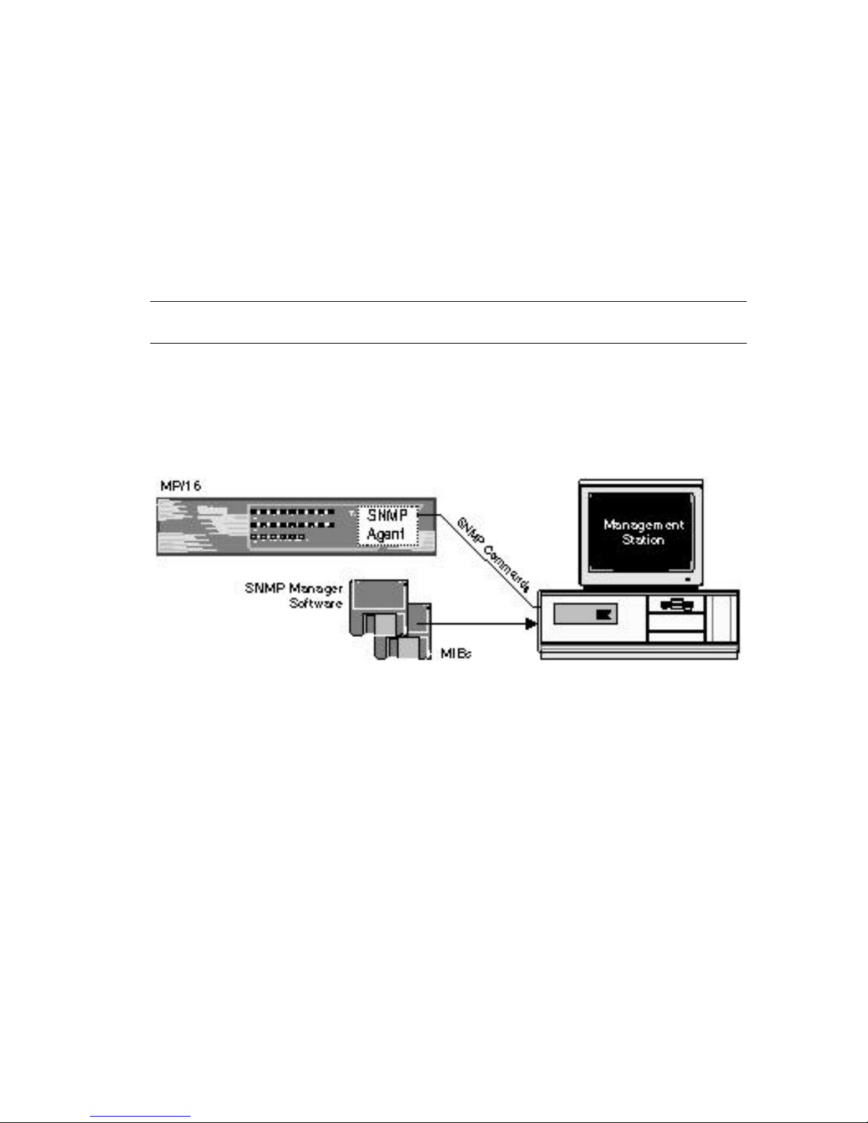
The Simple Network Management Protocol (SNMP) is a widely
supported management protocol that provides remote control and
monitoring of network devices such as the MP/16. The following
figure illustrates the basic components of SNMP management.
Figure 1-1. Basic Components of SNMP Management
SNMP Agent
A special SNMP agent contained in the MP/16 interprets SNMP
commands and relays them to the managed objects in the MP/16.
Management Station
As a network manager, you are responsible for setting up the
Management Station, a PC running SNMP management software
from which you manage the MP/16 and other devices in your
network.
SNMP Management Software
SNMP management software runs on the Management Station
(MS), and serves as a user interface for issuing SNMP commands to
all managed network devices, including the MP/16.
Page 8

1-2 Overview
SNMP Commands
There are three SNMP commands: Get, Set, and GetNext. The
Management Station issues SNMP commands to set parameters or
perform other actions on a managed device.
MIBs
A Management Information Base (MIB) is a list of objects with
variables that pertain to a particular type of device, such as a
modem. MIBs are necessary when sending or receiving SNMP
information between the Management Station and the MP/16. For
example, the Total Control Modem MIB defines an object for each
modem parameter. When you send a command from TCM to
change a modem setting, TCM references the Modem MIB so that
the command can be properly coded, translated by the MP/16
management module, and applied to the modems. Likewise, when
TCM polls the MP/16 for the status of the modems, TCM uses the
Modem MIB to interpret the SNMP information gathered and
display the correct settings and LED status for each modem.
NOTE: Total Control Manager/SNMP (TCM) is a Windows-based
SNMP management software developed by U.S. Robotics
specifically for Total Control products such as the MP/16. It’s
virtual front panel display and configuration windows provide a
user interface that streamlines management functions. TCM
eliminates the need to deal with MIBs when communicating with
U.S. Robotics Total Control devices.
Page 9
Applications 1-3
Applications
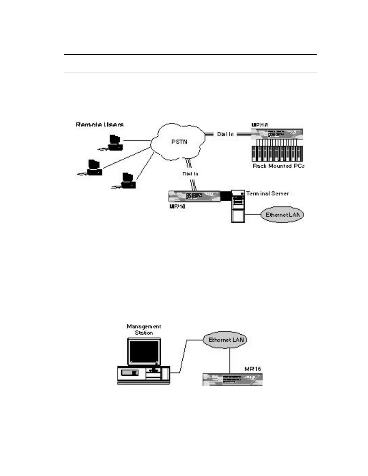
The MP/16 modem pool integrates sixteen modems for dial-up
access to terminal servers, front-end processors, bulletin boards,
email, or other resources.
Figure 1-2. Typical Setups for Dial-up LAN Access
SNMP management allows you to operate the MP/16, monitor line
activity, and perform dial-up accounting from across a LAN or
WAN (dial-up) connection.
Management from a LAN
The LAN port on the MP/16 allows you to establish an SNMP
connection over a LAN.
Figure 1-3. Management Station on the LAN
Page 10
1-4 Overview
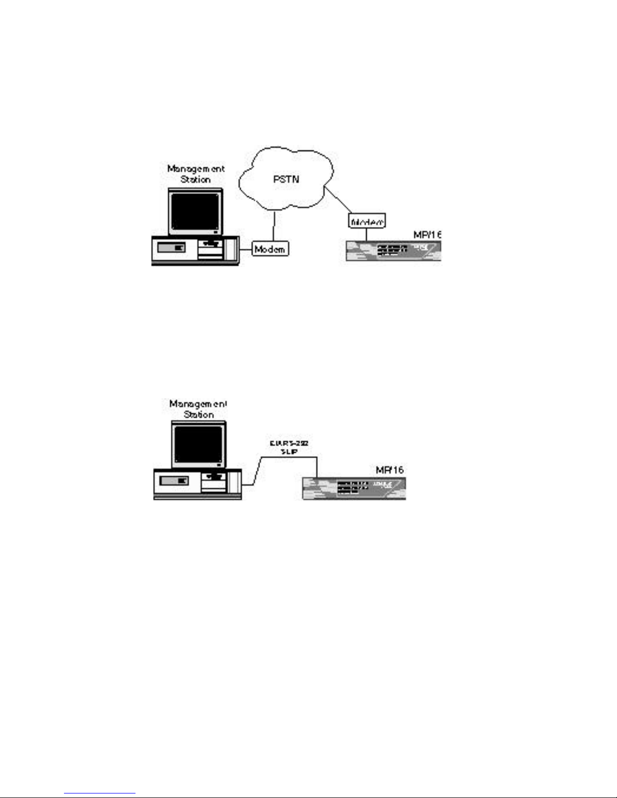
Dial-up Management
The Console port allows SNMP management over dial-up SLIP
connections from Management Stations in remote locations.
Figure 1-4. Dial-up Management
Direct Management
A local SLIP connection can be made by connecting the
Management Station to the MP/16’s Console port using a standard,
EIA RS-232 connection.
Figure 1-5. Direct SLIP
Page 11

Modem Features 1-5
Modem Features
33.6 Kbps Connections
In addition to supporting normal connect speeds under V.34, V.FC,
V.32 terbo, V.32 bis and older ITU-T standards, the modems in the
MP/16 can connect at 31.2 Kbps and 33.6 Kbps when connecting
with other U.S. Robotics modems with 33.6 Kbps capability.
Custom Power-on/Reset Defaults
Custom configurations can be stored as power-on/reset defaults in
the modem’s Non-Volatile Random Access Memory (NVRAM).
Software Upgrades
Flash ROM make the modems software upgradable.
Fax Capability
Supports Class 1 or Class 2.0 facsimile software and the V.17 fax
protocol.
Link Security
Link Security prevents unauthorized access at the modem level—
before allowing any type of network connection.
Optional Cellular
If you purchased the MP/16 with cellular, the modems can answer
calls across cellular links using ETC and MNP10.
Page 12

1-6 Overview
Page 13

Summary 2-1
Chapter 2 Installation
Summary
1 Check to make sure you have all the required accessories
(page 2-2).
2 Familiarize yourself with the location of the connectors and
DIP switches on the unit’s back panel and the function of the
LEDs on the front panel (pages 2-3 –2-4).
3 Place the unit on a desktop or in a rack (page 2-4).
4 Plug the unit into a power source (page 2-6).
5 Assign IP addresses to the MP/16 (pages 2-7–2-10).
6 Setup the MP/16 for either LAN (pages 2-11–2-12) or dial-up
SLIP management (pages 2-13–2-17)
7 Connect the modems to your Data Terminal Equipement (DTE)
and analog phone source (page 2-18) and set the modem DIP
Switches (pages 2-19–2-20).
8 Set up your Management Station. Be sure to compile the MIBs
on the disk that came with the MP/16 into your SNMP
management software. See your SNMP management software
guide. If you are using Total Control Manager/SMP (TCM) to
manage the MP/16, you will not need this disk, as these MIBs
are included with the software. See the TCM
Installation/Configuration Roadmap for instructions on
compiling the MIBs.
Page 14

2-2 Installation
Required Accessories
The Total Control MP/16 comes with the following materials:
♦ Power cord
♦ 16 analog phone cords
♦ One RJ45-to-DB-25 serial cable
♦ One null mo dem adapter
♦ Four rubber feet for placing the unit on a desktop.
♦ Two metal flanges and four screws for rack mounting the unit.
♦ One 3.5" floppy diskette containing the Total Control MP/16
Enterprise Specific MIBs
In addition to the provided hardware, you must have the following
to successfully install the Total Control MP/16:
♦ A PC running terminal emulator software.
♦ A good, working knowledge of TCP/IP and an addressing
strategy for your network. Your addressing strategy should
take into account the size of the network, the number of
physical networks, expected growth, and maintenance.
♦ EIA RS-232 serial cables to attach the modem ports to the
router, terminal adapter or other Data Terminal Equipment
(DTE).
If your equipment does not provide an RJ45 interface, consider
the purchase of one of three kinds of U.S. Robotics cable kits.
The following kits are available. Ask your distributor for
ordering information.
Page 15
The Unit 2-3
U.S. Robotics Cable Kits
DB-25 Kit. Contains eight RJ45 cables with RJ45-to-DB-25
adapters. For use with EIA-standard 25-pin DTE
interfaces.
DB-9 Kit. Contains eight RJ45 cables with RJ45-to-DB-9
adapters. For use with EIA-standard 9-pin DTE interfaces.
Cisco Kit. Contains one 8-to-1 cable for Cisco Systems 2500
Series Access Products.
The Unit
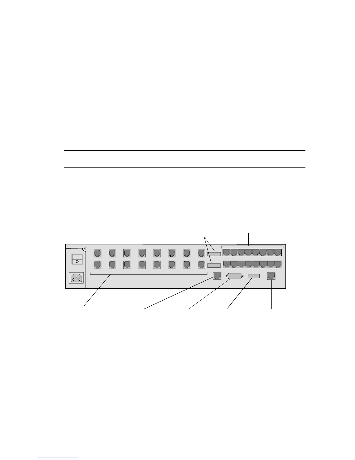
Back Panel
1 2 3
4
5
6
7
8
9
10 11 12 13 14 15 16
RJ11 Telco Jacks
Modems 1-16
Sixteen telephone
cords are provided
10base T
Ethernet
Connector
For SNMP
management
only
10base 5
Ethernet
Connector
For SNMP
management
only
Console Port
DIP Switches
Console Port
DIP Switch 3
OFF for configuration
ON for direct SLIP or
Dial-up (WAN)
management
EIA RS-232 Serial Ports
Modems 1-16
Connect to DTE
Serial cables are not
provided
Modem
DIP Switches
First set controls
modems 1-8
Second set controls
modems 9-16
Figure 2-1. MP/16 Back Panel
Page 16
2-4 Installation
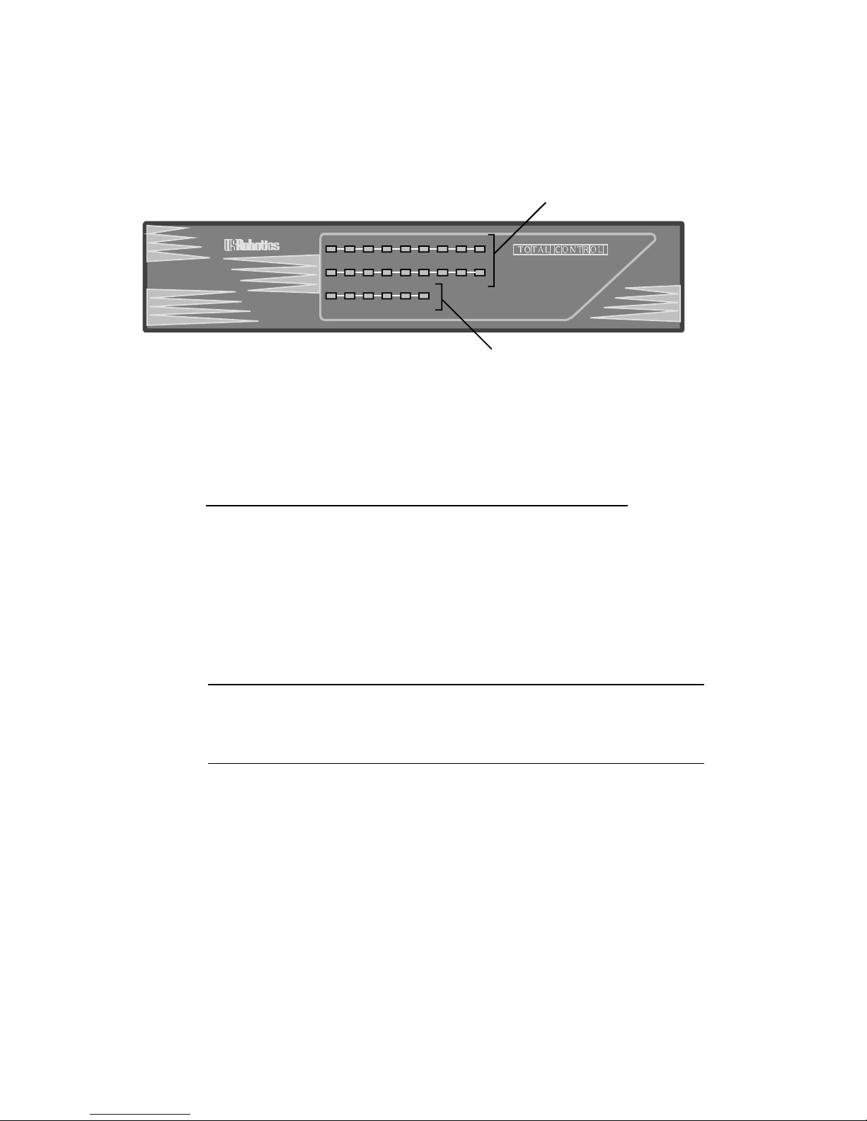
Front Panel
TM
MP/16 V.34
with SNMP Management
16
RUN/
FAIL
1 2 3 4 5 6 7 8
RUN/
FAIL
9
10
11
12
13 14
15
RUN/
FAIL
STATUS LAN TX LAN RX WAN TX WAN RX
Management LEDs
Modem LEDs
Figure 2-2. MP/16 Front Panel
Modem LEDs
Colors LEDs
Run/Fail Modems 1-16
Off off idle
Green power on online
Orange — dialing
Flashing green — testing/SDL
Red critical failure critical failure
Management LEDs
LED Color Status
RUN/Fail Solid Green Normal
Solid Red Critical SNMP agent failure
Flashing Green Testing/SDL
Flashing Green/Red Non-critical failure
STATUS Solid Green Normal
Solid Red Critical MP/16 failure
LAN TX Green Transmitting on LAN port
LAN RX Green Recieving on LAN port
Orange Rate of incoming ethernet data
(heavy traffic) exceeds processing
capability of system
Red Rate of incoming Ethernet data
(heavy traffic) exceeds memory
resources of system
WAN TX Green Transmitting on WAN port
WAN RX Green Recieving on WAN port
Page 17
Placement 2-5
Placement
The MP/16 must be placed in a location with access to the
following:
♦ A standard grounded 115V AC wall socket or power supply
♦ Analog phone lines
♦ The router, terminal adapter, or other DTE to which you will
connect the modem EIA RS-232 ports
♦ An Ethernet LAN segment, if you plan to manage the MP/16
from a LAN. An isolated LAN segment is recommended
Placing the MP/16 on a Desktop
Stick the rubber feet (included) into the four recesses on the bottom
of the unit and place on a flat, hard surface. This leaves room
below for adequate ventilation.
CAUTION:
! Use the rubber feet to provide ventilation under the unit.
! Do not block the fan on the side of the unit.
! Do not stack MP/16s more than 8 units high.
Mounting in a Rack
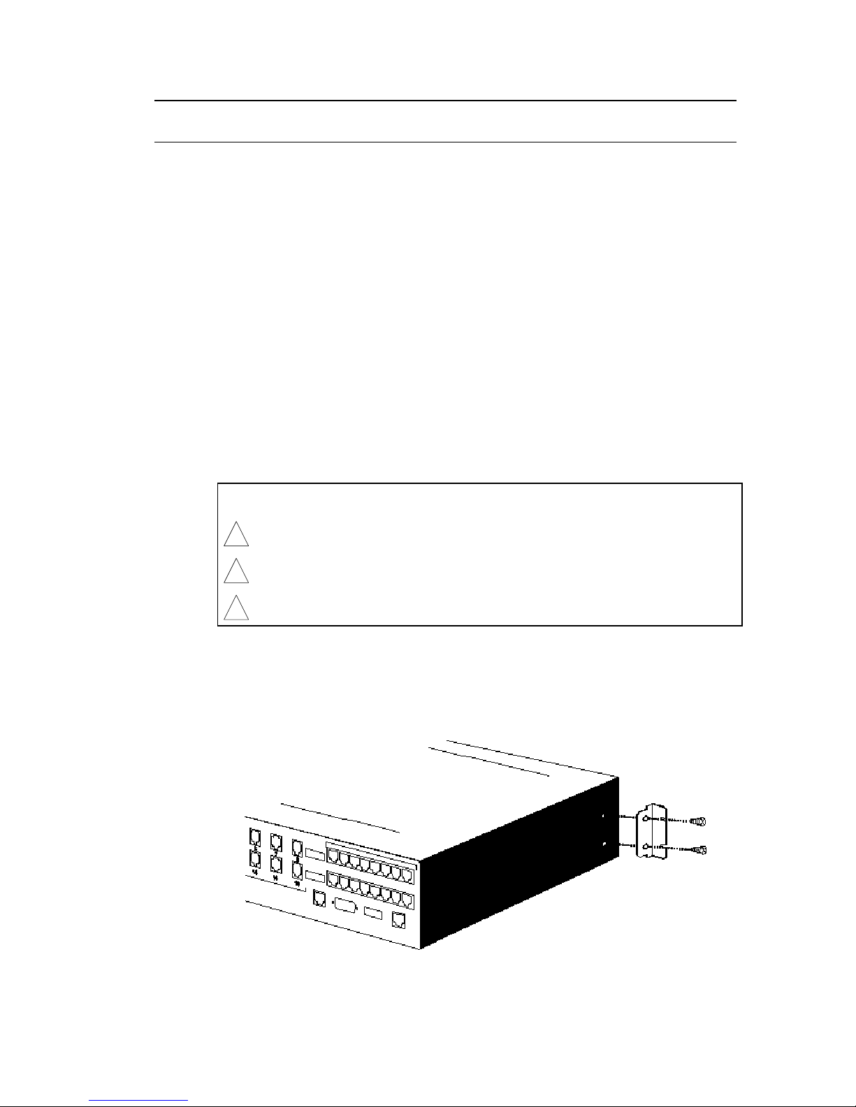
1 Attach the provided flanges to the sides of the MP/16 using the
four screws that came with them.
Figure 2-3. Attaching the Flanges
Page 18
2-6 Installation
2 Use four of the bolts and anchors that came with your rack to
bolt the flanges to the front vertical railing. Begin by inserting
and tightening the bottom two bolts, then the top two.
! Leave room above and below for adequate ventilation.
Use fan trays if necessary.
Power
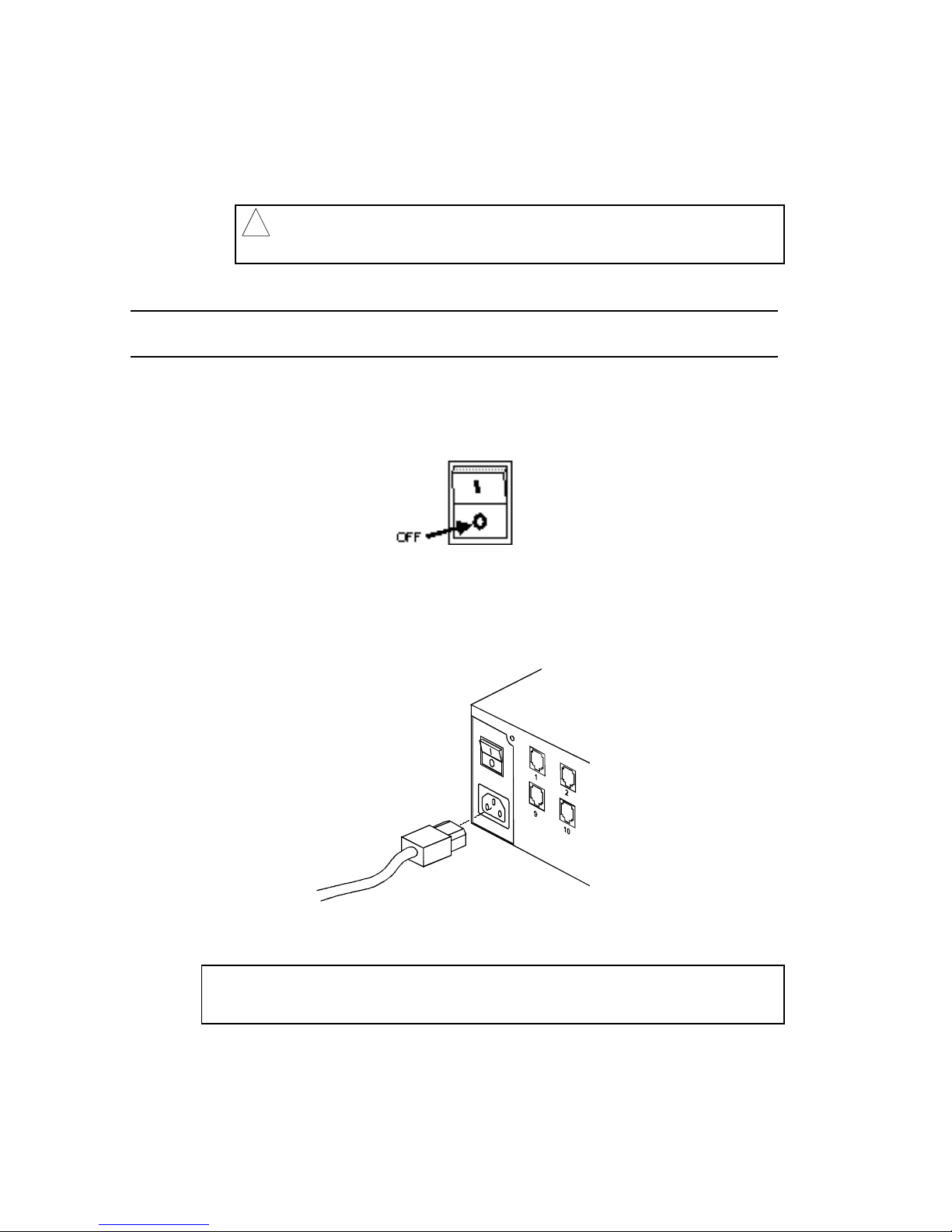
Be sure the power switch on the MP/16 is turned OFF before
plugging in the power cable.
The supplied power cable plugs into the back of the MP/16 and
connects to any standard, grounded 110v, 60Hz AC electrical
outlet.
Figure 2-4. Power Cord
NOTE: You may want to install a line noise filter/surge protector
between the power source and the MP/16.
Page 19

Assigning IP Addresses 2-7
Assigning IP Addresses
NOTE: This section assumes that you have an addressing
strategy for your network and have already chosen an IP address
and subnet mask for the MP/16.
Default Addresses
The MP/16 Management ports (LAN and Console) are configured
to default to the following Class C IP addresses. We recommend
changing these defaults to fit your network IP addressing scheme.
Table 2-1. Default IP Addresses
Port Default IP Address
LAN Port 192.77.203.193
WAN (Console) Port 192.77.203.65
Subnet Mask 255.255.255.192
Gateway 192.77.203.126
Accessing the Configuration User
Interface (UI)
The MP/16’s Configuration User Interface (UI) allows you to
change IP address information. To access the Configuration UI,
you need the following:
♦ An RJ45-to-DB-25 serial cable (provided)
♦ A null modem adapter (provided)
♦ A PC running a TTY terminal emulator (or communications
program in terminal mode) to act as the configuration console
Page 20
2-8 Installation
Follow these steps:
1 Make certain that the unit is powered off.
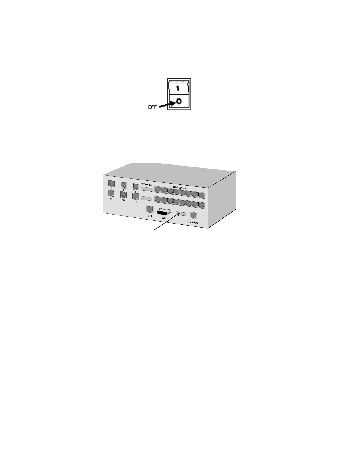
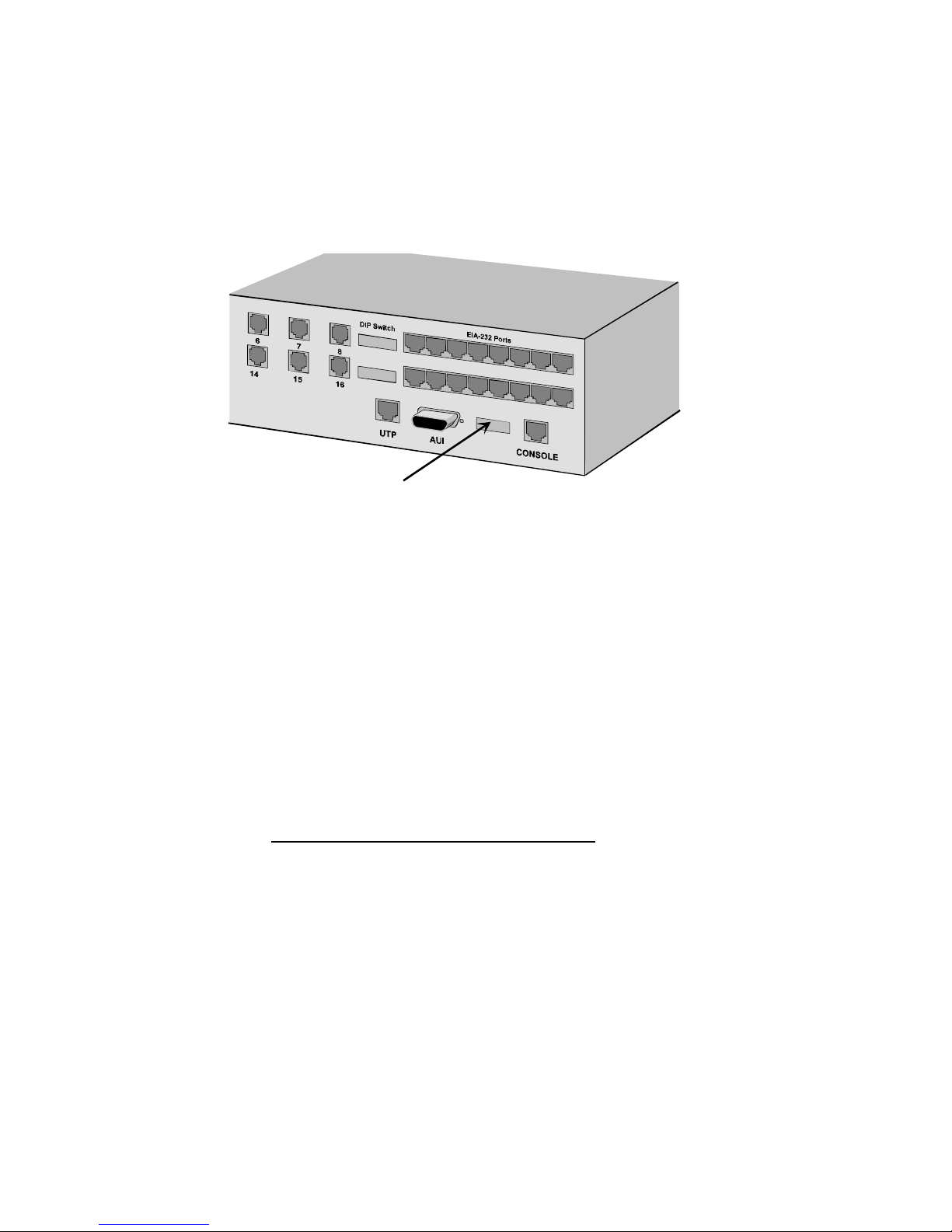
2 Set Console DIP switches. The Console DIP switches are
located to the immediate left of the Console port. (See figure
2-5 below).
Console
DIP Switches
Figure 2-5. Location of Console DIP Switches
♦ DIP switch 3 must be is in the UP (OFF) position.
♦ Use DIP switches 1 and 2 to set the Console port speed to
the highest rate supported by your PC and communication
software (if unsure, leave at 9600 or set it to 19.2K).
The following table reflects the table labeled SPEED
printed on the back of the MP/16.
Table 2-2. Console Port Speed
Switch 1 Switch 2 Speed
OFF OFF 9600
OFF ON 19.2K
ON OFF 38.4K
ON ON 57.6K
Page 21
Assigning IP Addresses 2-9
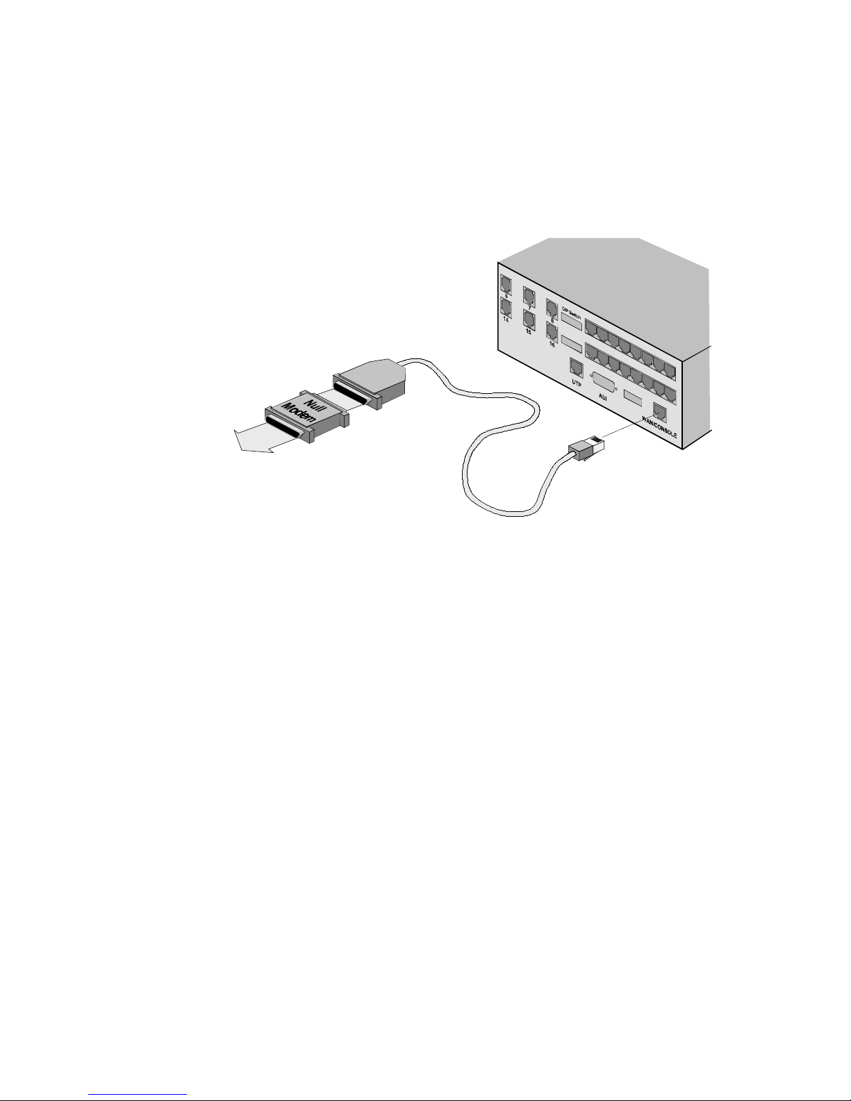
3 Connect the configuration console to the MP/16. Use the
provided RJ45-to-DB-25 serial cable with the provided null
modem adapter (see Figure 2-6 below) to connect the MP/16
Console port to a serial port on the PC or terminal you are
using as the configuration console.
To PC or
Terminal
Figure 2-6. Connecting to the Console Port
4 Power on the MP/16. The Run/Fail LED on the bottom row of
LEDs flashes while the MP/16 runs its self-diagnostic. After
the MP/16 has finished booting, the Run/Fail light should be
solid green.
5 Power on the configuration console. Run the terminal
emulator (or communications program in terminal mode). It
must be set to the same port speed that you set the Console port to in
step 2. It must also be set for hardware flow control (CTS/RTS)
with a data format of 8-N-1.
6 Press Return. Press Return from the configuration console.
The User Interface (UI) Main Menu should appear. If the UI
Main menu does not appear, check the following:
♦ The port speed setting in your communications software
must match the port speed on the MP/16 (set in step 2).
♦ Your communications software must be set for hardware
flow control (CTS/RTS) and a data format of 8-N-1.
Page 22

2-10 Installation
♦ The null modem adapter must be attached to the serial
cable and plugged into a COM port on the configuration
console.
♦ The communications softwa re must be set for the COM
port that the MP/16 is connected to.
The User Interface
After you have established a successful connection, the UI Main
menu should appear on the configuration terminal screen.
1 Type “1” at the Main menu prompt and press Enter to bring up
the Configuration menu.
2 Change the default IP addresses, subnet mask, and any other
management parameters. If necessary, refer to Appendix B,
Management Configuration Menu Guide.
3 IMPORTANT! Save settings to NVRAM. After completing all
IP address assignments, select Save Configuration to Non-Volatile
Memory (7) from the Configuration menu to save the settings to
the MP/16’s NVRAM. Make sure that Console DIP Switch 4 is
in the UP (OFF) position so that the MP/16 boots from the
NVRAM configuration.
Remote Configuration
Optionally,configuration can be performed from a remote location
by attaching a modem to the Console port to which you dial in
from a remote configuration console. Follow the same basic
procedure for local configuration, but use the following guidelines:
♦ Set the modem’s port speed to match the MP/16’s Console
port speed. For U.S. Robotics modems, attach a PC running
communications software to the modem’s serial port, set the
software for the right speed, and send the modem an AT
command. The modem matches its port speed to the rate at
which the AT command is sent.
♦ Connect the modem to the MP/16 Console port, but do NOT
use the null modem adapter.
♦ Dial into the modem from the remote configuration console
using a communications program in terminal mode.
Page 23

Management Over a LAN 2-11
Additional Configuration Options
In addition to setting the IP addresses and subnet mask, the
Configuration UI allows you to do the following:
♦ View Local Ethernet MAC Address. The MP/16 has a unique
MAC address burned in at the factory. This address cannot be
changed.
♦ Set Local SNMP Community Strings , which determines the
level of access for the MP/16 from a Management Station. The
default Community strings are “public” for read-only and
“private” for read-write.
♦ Re-initialize Authorized Access List . This clears the authorized
access list as set in Total Control Manager/SNMP (TCM),
granting access to all users.
NOTE: If you are using TCM/SNMP, these options may be set at
a later time through the TCM interface.
Management Over a LAN
Two types of Ethernet connectors on the back of the MP/16 (AUI
and UTP) allow SNMP management over a LAN. The LAN IP
address and subnet mask are assigned through the MP/16 User
Interface (UI) as explained in the previous section.
NOTE: We suggest the MP/16 be on an isolated LAN segment
that does not receive Medium Access Control (MAC) layer
broadcasts. This will prevent the MP/16 from expending too
much time on nonproductive traffic and allow it to concentrate its
resources on other, real-time management functions.
Page 24
2-12 Installation
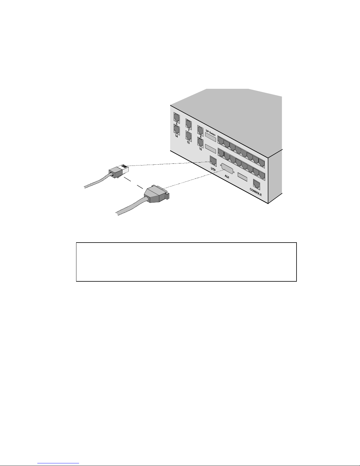
Plug the thick net (10Base5) or twisted pair (10BaseT) network
cable into the appropriate socket on the MP/16. The MP/16
automatically detects which type of network cable you are using
when you power it on.
or
Twisted Pair
(10BaseT)
Thicknet
(10Base5)
Figure 2-7. Cabling to a LAN
NOTE: If there is no Ethernet cable attached to the MP/16 when
you power it on, the MP/16 defaults to the AUI port. If you later
decide to connect to the UTP port, you must reset the MP/16 by
powering it off.
ThinNet Installations
If you want to connect the MP/16 to “thin Ethernet” coaxial cable,
you will need a Multiple Access Unit (MAU) to convert from one
of the existing connectors.
Page 25

Dial-Up Management 2-13
Dial-Up Management
The Console port on the back of the MP/16 allows you to manage
it using a dial-up SLIP (WAN) connection. The Console port must
be assigned a WAN IP address and subnet mask. If you have not
already done so, follow the steps for assigning IP addresses earlier
in this chapter before continuing.
To set up the MP/16 for dial-up management, you will need the
following:
♦ A modem. We suggest using a separ ate, external modem. For
instructions on using one of the modems in the MP/16, see
Using an MP/16 Modem for Dial-up Management at the end of
this section.
♦ A female DB-25 or DB-9 to RJ45 cable, such as the ones that
come with the optional U.S. Robotics serial cable kit.
♦ A terminal or PC, running communications software to
configure the modem.
Page 26
2-14 Installation
Use the following steps to set up the MP/16 for dial-up
management:
1 Set Console port DIP switches. The Console port DIP
switches are located to the immediate left of the Console port.
Console
DIP Switches
Figure 2-8. Location of Console port DIP Switches
♦ Set DIP switch 3 to the DOWN (ON) position. This
configures the Console port for management.
♦ Use DIP switches 1 and 2 to set the Console port speed to
the highest speed supported by the modem. For U.S.
Robotics High Speed modems, set the port speed at 57.6K.
The following table reflects the table labeled SPEED
printed on the back of the MP/16.
Table 2-3. Console Port Speed
Switch 1 Switch 2 Speed
OFF OFF 9600
OFF ON 19.2K
ON OFF 38.4K
ON ON 57.6K
Page 27

Dial-Up Management 2-15
2 Configure the modem. Connect a PC running a
communications program or terminal emulator to the modem.
a IMPORTANT: Set the communications software or
terminal emulator to the same serial port rate at which you
set the Console port in step 1.
b Configure the modem with the following settings:
Setting
Command
(for USR modems)
Auto Answer DIP Switch 5 OFF
Functional DTR DIP Switch 1 OFF/&D2
CTS flow control &H1
Fixed DTE rate &B1**
RTS flow control &R2
DSR override &S0
ITU-T answer sequence B0
Command mode local echo off DIP Switch 4 ON/E0
Online echo off F1
Suppress result codes DIP Switch 3 OFF/Q1
** U.S. Robotics modems fix their serial ports to match the rate at which AT
commands are sent to them across the serial port.
c If you are using a U.S. Robotics modem or your modem
contains NVRAM, you’ll probably want to save these
settings to the modem’s NVRAM so you don’t have to reenter them every time you power on the modem.
For U.S. Robotics modems, use the following command:
AT&W
Make sure that the modem is set to load settings from
NVRAM when powered on (DIP Switch 10 OFF).
Page 28
2-16 Installation
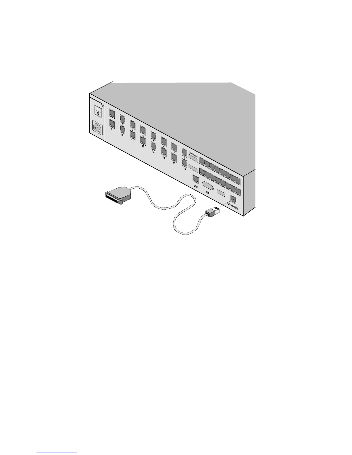
3 Connect the modem to the MP/16 Console port. Use the RJ45-
to-DB-25/DB-9 serial cable to connect the modem to the
MP/16 Console port as pictured below:
To external modem
Dial into modem from
configuration console
Figure 2-9. WAN connection using an external modem
Using an MP/16 Modem for Dial-up
Management
Use the same steps for setup as you would if you were using a
separate modem, with the following guidelines:
♦ In Step 2, Configuring the modem, don’t use the modem DIP
switches to configure the MP/16 modem if these settings are
going to conflict with those required to connect the other seven
modems to your DTE. Instead, use the equivalent AT
commands. AT commands that share functionality with DIP
switches can NOT be saved to the modem’s NVRAM.
However, once a management session is established, you can
use the Auto Configuration feature to save these setting in the
MP/16’s management NVRAM.
Page 29
Dial-Up Management 2-17
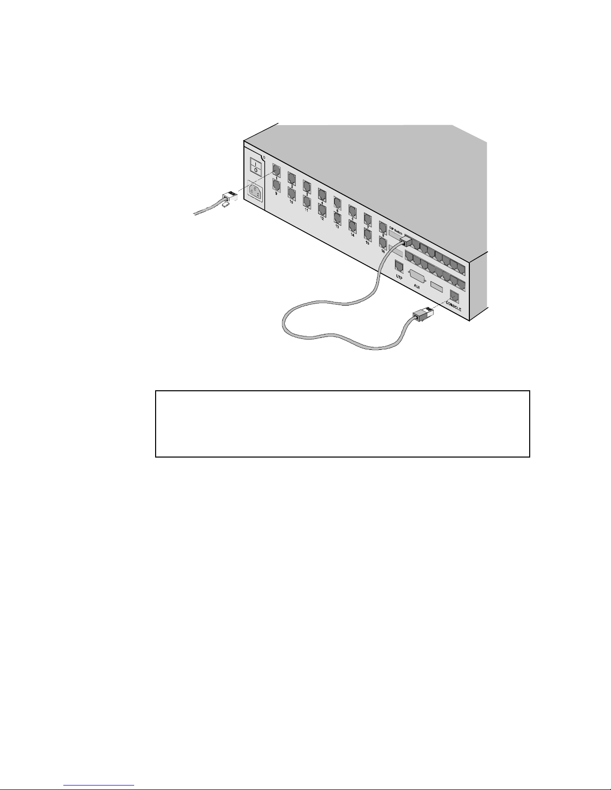
♦ In Step 3, cable the MP/16 modem to the Console port using a
standard RJ45-to-RJ45 cable. The following diagram illustrates
this setup:
RJ11 Plug
to TELCO
Figure 2-10. Using an MP/16 Modem for Dial-up Management
NOTE: If you use one of the modems in the MP/16 to dial in to
the MP/16, you will NOT be able to perform future upgrades to
the modems in the MP/16 through TCM without onsite
intervention.
Page 30
2-18 Installation
Modem Setup
Connecting to the Telephone Company
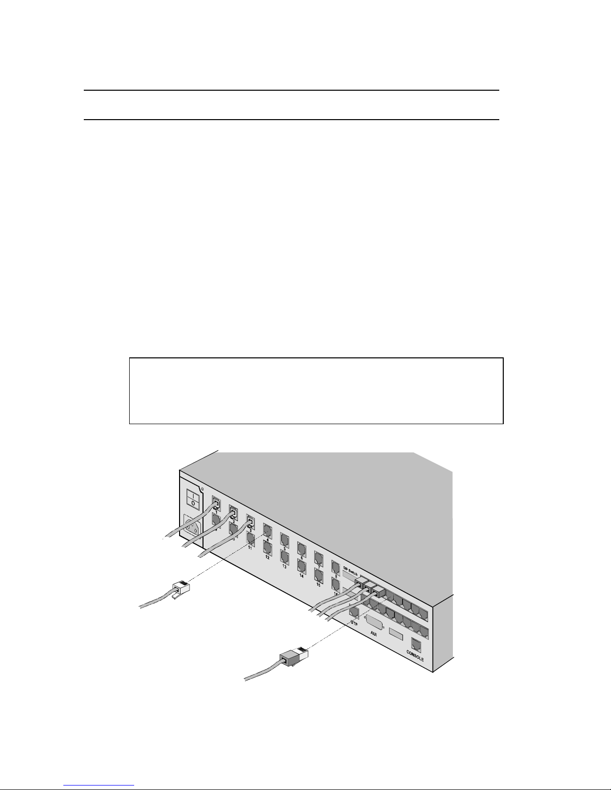
Plug the provided RJ11 telephone cords into RJ11 jacks the back of
the MP/16. The jacks are labeled 1-16 and marked Telco. Connect
the other end of the cables to your analog phone lines.
Connecting to Your DTE
The RJ45 serial ports for the modems in the MP/16 conform to the
EIA RS-232 standard for Data Communication Equipment (DCE)
devices. Standard RJ45 cables may be used to connect the modems
to any RJ45 Data Terminal Equipment (DTE) interface also in
conformance with the RJ45 EIA-232 standard.
NOTE: Not all equipment provides standard DTE EIA RS-232
interfaces. For RJ45 pin assignments, RJ-to-DB and DCE-to-DCE
pinout conversions, and other information useful for building
custom cables, see Appendix A.
RJ11 Plug
to TELCO
RJ45 Plug
to DTE
Figure 2-10. Cabling the Modems
Page 31
Modem Setup 2-19
NOTE: The Ethernet connectors on the MP/16 are used only for
SNMP management—they can NOT be used for data transfer to
or from the modems.
Setting Modem DIP Switches
The modem DIP switches define the basic power-on/reset defaults
for the modems in the MP/16. Use the table on the following page
to set the DIP switches for compatibility with your system.
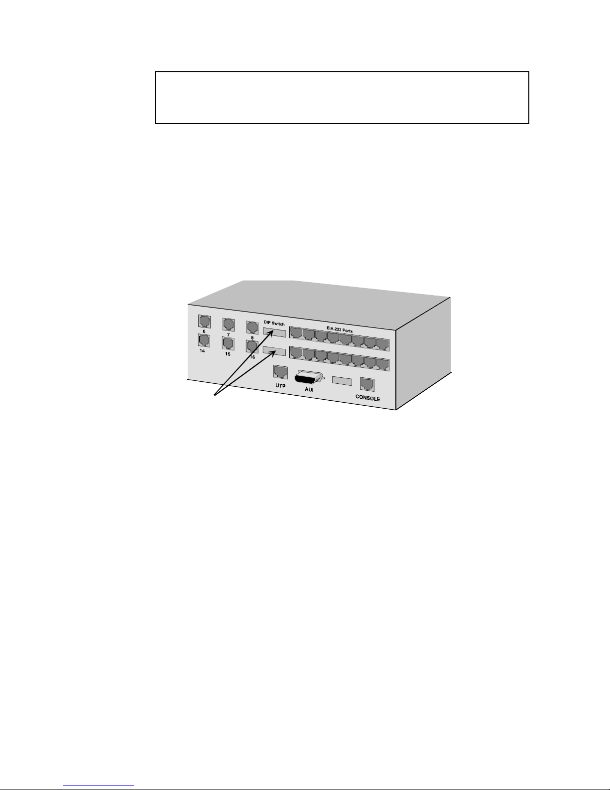
The following illustration shows the location of the modem DIP
switches:
Modem DIP
Switches
Figure 2-11. Location of Modem DIP Switches
The first set of DIP switches controls modems 1-8, and the second
set controls the same functions for modems 9-16. The UP position
sets the switch OFF; DOWN sets the switch ON.
Page 32

2-20 Installation
Table 2-4. Modem DIP Switch Functions
Factory
Switch Setting Function
1 OFF Data Terminal Ready Operations
OFF Normal DTR operations: computer must provide DTR
signal for modem to accept commands; dropping DTR
terminates a call
ON DTR always ON (Override)
2 OFF Verbal/Numeric Result Codes
OFF Verbal (word) results
ON Numeric results
3 OFF Result Code Display
OFF Result Codes suppressed
ON Result Codes displayed
4 ON Command Mode Local Echo
OFF Keyboard commands displayed
ON Echo suppressed
5 OFF Auto Answer
OFF Modem answers on first ring
ON Auto answer disabled
6 OFF Carrier Detect Operations
OFF Normal CD operations. Courier sends CD signal when
it connects with another modem, drops CD on
disconnect
ON CD always ON (Override)
7 OFF Auxiliary, DIP Switch 3 ON
OFF Result codes in Originate and Answer mode
ON Result codes in Answer mode disabled
8 ON AT Command Set Recognition
OFF Command recognition disabled (Dumb mode)
ON Enabledcommand set recognized (Smart mode)
9 ON Escape Code (+++) Response
OFF Modem hangs up and returns to Command mode
ON Modem maintains connection, returns to Command
mode
10 OFF Power-on/Reset Load Configuration Defaults
OFF Load settings from nonvolatile memory (NVRAM)
ON Load fail-safe settings (&F0 template) from ROM
Page 33

Modem Setup 2-21
Setting Default Configuration
NOTE: A modem can be easily configured for either hardware or
software flow control using the modem’s built in Configuration
Templates.
♦ From TCM, execute the HW Flow Control Def. or SW Flow
Control Def. command from the Actions/Commands window
♦ In the Total Control Modem MIB, the MIB objects are
loadHwFlowDflt (23) and loadSwFlowDflt(24).
For more information, see &Fn in Appendix D.
NVRAM Defaults
The modems are factory set to load NVRAM settings at power-on
or reset (DIP switch 10 OFF). These settings offer optimal modem
performance with most installations.
The following table lists default settings stored in NVRAM:
Table 2-5. Default NVRAM Settings
Setting Description
B0 ITU-T answer sequence
&M4 Normal/error control
&K1 Data compression
&H1 Transmit data flow control
&R2 Rec'd data hardware flow control—Enabled
&I0 Rec'd data software flow control—Disabled
&B1 Serial port rate—Fixed
&N0 Link rate select—Variable
X7 Extended Result code
&A3 Protocol result code subset
P Pulse dial
F1 Online local echo—Disabled
&T4 Remote Digital Loopback (RDL)
&L0 Normal analog phone line
&S0 Data Set Ready (DSR) Override
&Y1 Break handling—Clear buffer, send immediately
&Z0–3=0 Stored telephone number—Blank
&P0 Pulse dial make/break ratio—U.S./Canada
&G0 Guard tone—U.S./Canada
Page 34

2-22 Installation
Data Format
The modem detects word length, parity, and DTE rate when sent
an AT command from a DTE. Set your software to the desired
word length, parity, and serial port rate defaults before sending the
modem any commands. Default values are 8-N-1 and 19.2 Kbps
for systems where the modem is not sent AT commands.
Changing NVRAM Settings
If your system requires changes to the modem’s default
configuration, you can change the settings stored in NVRAM.
Changing NVRAM settings is a two-step process:
1 Configure the modem with the desired settings.
2 Save the current modem settings to the modem’s NVRAM
using the Store to NVRAM command or to the MP/16’s
NVRAM using the Auto Configuration feature.
Using SNMP Management to Configure the modems
We suggest using your SNMP management software to configure
the modems. Modem configuration using management offers
many advantages over using AT commands, including the
following:
♦ Group configuration. With management, all 16 modems may be
configured at one time, and these settings saved as poweron/reset defaults.
♦ Remote Configuration. Configure the modems from any SNMP
management station on your LAN or WAN.
♦ Multiple MP/16 Configuration. Settings for one MP/16 may be
duplicated for any number of units.
If you are using Total Control Manager/SNMP (TCM) , consult the
TCM Installation/Configuration Roadmap or Software Guide. If
you are using other SNMP management software, see Chapter 3 of
this guide, Using Total Control MIBs, and your software’s user
manual.
Page 35

Modem Setup 2-23
Special Applications
Chapter 4 contains information on configuring the MP/16 for
special features and applications such as Link Security, Cellular,
Result Codes, and Leased Line. It includes MIB object names,
TCM commands, and AT commands for setting modem
parameters.
Using AT Commands
Optionally, you can use AT commands to configure the modem.
See the Appendix C for instructions on using AT commands and
Appendix D for an alphabetical AT command reference.
Page 36

2-24 Installation
Page 37

Using Total Control MIBs 3-1
Chapter 3 Using Total
Control MIBs
This chapter is provided for those who are not using Total Control
Manager/SNMP (TCM) software. Users of TCM need not concern
themselves with the contents of this section.
This section assumes that the reader has prior knowledge of the
SNMP protocol and the concept of the Management Information
Base (MIB). No explanation of the SNMP protocol is provided
here. For additional information on this topic, see The Simple Book
by Marshall T. Rose.
Total Control MIBs and the U.S. Robotics
Enterprise
The Total Control MP/16 uses a subset of the Total Control MIBs.
They are identical to compatible revisions of MIBs used with other
U.S. Robotics enterprise equipment.
The complete set of Total Control MIBs are comprised of the
standard MIBII, the DS1 MIB, and a number of enterprise-specific
MIBs. The Assigned Numbers Authority has reserved enterprise
number 429 for U.S. Robotics. All of the enterprise-specific Total
Control MIBs reside under this node on the enterprise sub-tree.
Total Control MIB Terminology and the
MP/16
When applying Total Control MIBs to an MP/16, use the following
guidelines:
♦ Modems 1-8 are slot 1, channels 1-8; modems 9-16 are slot 2
channels 1-8.
♦ The MP/16 is referred to as a chassis.
♦ The term NMC describes a chassis’s management module.
Page 38

3-2 Using Total Control MIBs
♦ The terms NAC or “card” refer to the modem modules.
♦ The modem modules and management module occupy slots
1,2, and 3 from top to bottom.
Command Tables
Understanding the concept of the command table is important and
necessary to fully utilize the management capabilities of Total
Control. The concept of this table was borrowed from RFC1229
(Generic Extensions to the Interfaces Table), but was enhanced to fit
the needs of U.S. Robotics.
The basic functionality provided by the command table is the
ability to use an SNMP SET request to activate an action or
command. The command table also provides for parameter
passing and result polling. In addition, a mechanism for handling
multiple management stations was implemented to help in
situations where more than one Network Manager is trying to issue
a command at the same time.
A typical use of the command table follows:
1 An SNMP SET operation is used to set the Function object.
Issuance of this SET operation also internally sets the read-only
ReqId object to the value of the request-id field in the SNMP
SET PDU.
2 If the MP/16 is able to handle the command, the read-only
Result object is set to inProgress(3) and activation of the
command begins.
3 If the command is not supported by the particular device for
which the command was sent, the Result object is set to
notSupported(4) and the command is ignored.
4 If the device is in a state such that it is unable to execute the
command at the particular time it was issued, the Result object
is set to unAbleToRun(5) and the command is ignored.
5 At this time, the management station issues SNMP GET
requests to repeatedly poll the Result and Code of the
requested command.
Page 39

Using Total Control MIBs 3-3
If the Result changes to success, the requested command is
complete.
If the Result changes to aborted(6) or failed(7), the Code object
reveals a further description of the reason for which the requested
command could not be done.
Additional Command Table Features
The Param object can be used to pass parameters to the command
table. Most commands do not require additional parameters. If
used, this parameter must accompany the Function object in a
single SET PDU.
The Force object can be used to force the command to be issued in
cases where the proxy agent would otherwise warn the Network
Manager and say it was unAbleToRun(5). One such example of
this is if the requested function is to reset a modem that is currently
in a connected state. If used, this parameter must accompany the
Function object in a single SET PDU or be set prior to SETting the
Function object.
Lastly, the command table makes provisions for the environment
where multiple management stations are possible. Two objects,
MgtStationId and ReqId, are used for this purpose. MgtStationId is a
writeable object that is provided for optional use by the
management station. If desired, it can set this object to a unique
value in the same PDU as is used to set Function, Param and Force.
The value of the request-id field of the SNMP SET (used to set the
Function) is internally stored and returned upon GETting the readonly ReqId. While GETting the command Result and Code, it makes
sense to GET MgtStationId and ReqId in the same PDU to guarantee
that the results the management station receives are related to the
command that it had requested (and not some other management
station).
The proxy agent will generally not allow a second command of the
same type as one already in progress for a given device. However,
after completion of one command, it is possible that a second
command could be issued and received before a management
station had been able to GET the results of the first command. This
is the reason for the additional complexity using MgtStationId and
ReqId.
Page 40

3-4 Using Total Control MIBs
Supported MIB II Groups
The U.S. Robotics MIBs are fully MIBII compliant, but all MIBII
groups are not mandatory. Only those applicable to the MP/16
have been incorporated here.
at
Although this group has been deprecated (will become obsolete in
the next MIB version), the MP/16 implements it for MIBI
compatibility as defined in MIBII.
egp
The MP/16 does not support the EGP group, as it does not
implement the Exterior Gateway Protocol.
icmp
The MP/16 supports the mandatory ICMP (Internet Control
Message Protocol) group.
interfaces
The MP/16 supports three rows in the interfaces table: one for the
WAN port interface, one for the LAN port interface, and one for
the loopback interface.
ip
The MP/16 supports the mandatory IP (Internet Protocol) group.
snmp
The MP/16 does support the mandatory SNMP (Simple Network
Management Protocol) group.
system
The MP/16 supports the mandatory system group defined in
MIBII.
tcp
The MP/16 does not support the TCP (Transmission Control
Protocol) group, as it does not implement the TCP protocol. All
NMC functionality is currently implemented through UDP.
transmission
The MP/16 does not currently implement the transmission group
for its own Ethernet interface.
Page 41

Using Total Control MIBs 3-5
udp
The MP/16 supports the mandatory UDP (User Datagram
Protocol) group.
Page 42

3-6 Using Total Control MIBs
The Chassis MIB
The Total Control chassis MIB is an enterprise-specific MIB loosely
based on an early draft standard under development by the
Chassis MIB Working Group (since disbanded), under direction of
the IETF (Internet Engineering Task Force). The Total Control
chassis MIB provides SNMP identification and indexing for
modems and other managed modules in the Total Control MP/16.
Internet ID
iso.org.dod.internet.private.enterprises.usr.nas.chs =
1.3.6.1.4.1.429.1.1
Slots and Entities
A full-scale chassis, such as the Total Control Enterprise Network
Hub, contains up to 17 slots. Each slot can house any of several
removable managed modules called Network Application Cards
(NACs), often referred to simply as “cards.” A card can occupy
any slot in the chassis, and can contain various manageable entities ,
depending on what type of card it is.
The term card is used to describe a managed module in the MP/16,
while slot is used to describe its location. Entity appropriately
describes each of the eight modems in each MP/16 modem module
and the SNMP proxy agent in the management module.
Slot and Entity Tables
The chassis MIB includes two main tables: the first defines slots
(uchasSlotTable) and the second table defines the manageable
entities (uchasEntityTable) that appear in a card or module.
The slot and entity tables are sparse tables. That means that there
can be "holes" in the tables, or missing rows where modules or
entities may not be physically present. The chassis’s proxy agent
adds rows to the slot table for each card discovered in a chassis,
and rows to the entity table for each managed entity found on
those cards.
Page 43
The Chassis MIB 3-7
For the MP/16, it is not possible to add or remove modules as you
might in a Total Control Network Hub chassis. The number of
slots remains constant, as well as the entities for the modules that
correspond to those slots.
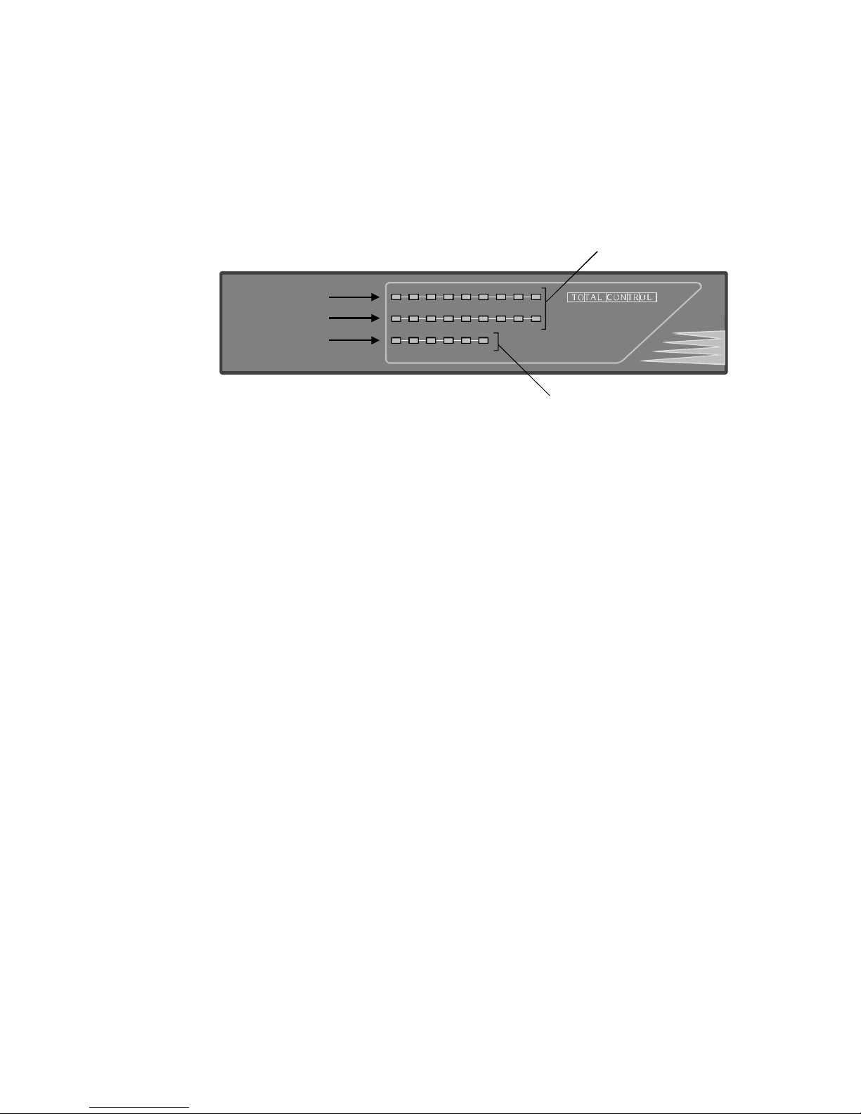
The following diagram displays how slots are defined for the Total
Contol MP/16.
TM
MP/16 V.34
with SNMP Management
16
RUN/
FAIL1234
5
6 7 8
RUN/
FAIL9101112131415RUN/
FAIL
STATUS
LANTXLANRXWAN TX
WAN RX
M
Slot 3
Slot 1
Slot 2
Management Module (NMC)
Modem Modules
Figure 3-1. Slot Index for MP/16
The way an entity index is computed is by the formula:
EI=(1000*S)+E
Where: EI is the entity index
S is the slot number of the card on which the entity
resides
E is the entity number (E=0 for card-level entities)
The following table reflects the entity index for the 16 modem
channels in the MP/16. Slot 3 refers to the MP/16 management
module (NMC), and always has an entity index of 3000.
Page 44

3-8 Using Total Control MIBs
Table 3-1. MP/16 Entity Index
Slot Entity Entity Index
1 Modems 1–8 1001–1008
2 Modems 9–16 2001–2008
3 Management (NMC) 3000
The indexes to the entity table are the same as the indexes to other
MIB tables for a given entity. As an example, if a modem entity
has an entity index of 2001, then that same entity number is used to
index the modem MIB tables to GET and SET objects in the modem
MIB for that modem. See the section on the chassis MIB for further
details.
NOTE: If the value of uchasEntityOperStatus is ever failed for
one or more entities, the STATUS light on the bottom row of
LEDS turns red.
The Config Group
Most of the MIB objects in this group are self explanatory. The
exceptions would be uchasFrontPanelLedStates and
uchasFrontPanelLedColor. In general, these objects are bitmaps.
The current design handles up to 12 LEDs per module. Each LED's
information is encoded in a nibble (4 bits); therefore, each module
takes up 6 bytes out of the octet string. The total length of the octet
string is 102 bytes, although the MP/16 only uses the first 18 bytes
for slots 1–3. It is the responsibility of the management station to
know how many LEDs each module has on the front panel of the
MP/16. The MIB does not identify how many of the 12 nibbles for
each module carry useful information.
In addition to LED state and color, a few of the bits in these objects
are used for additional information. The bit definition for these
three objects is shown below.
Page 45
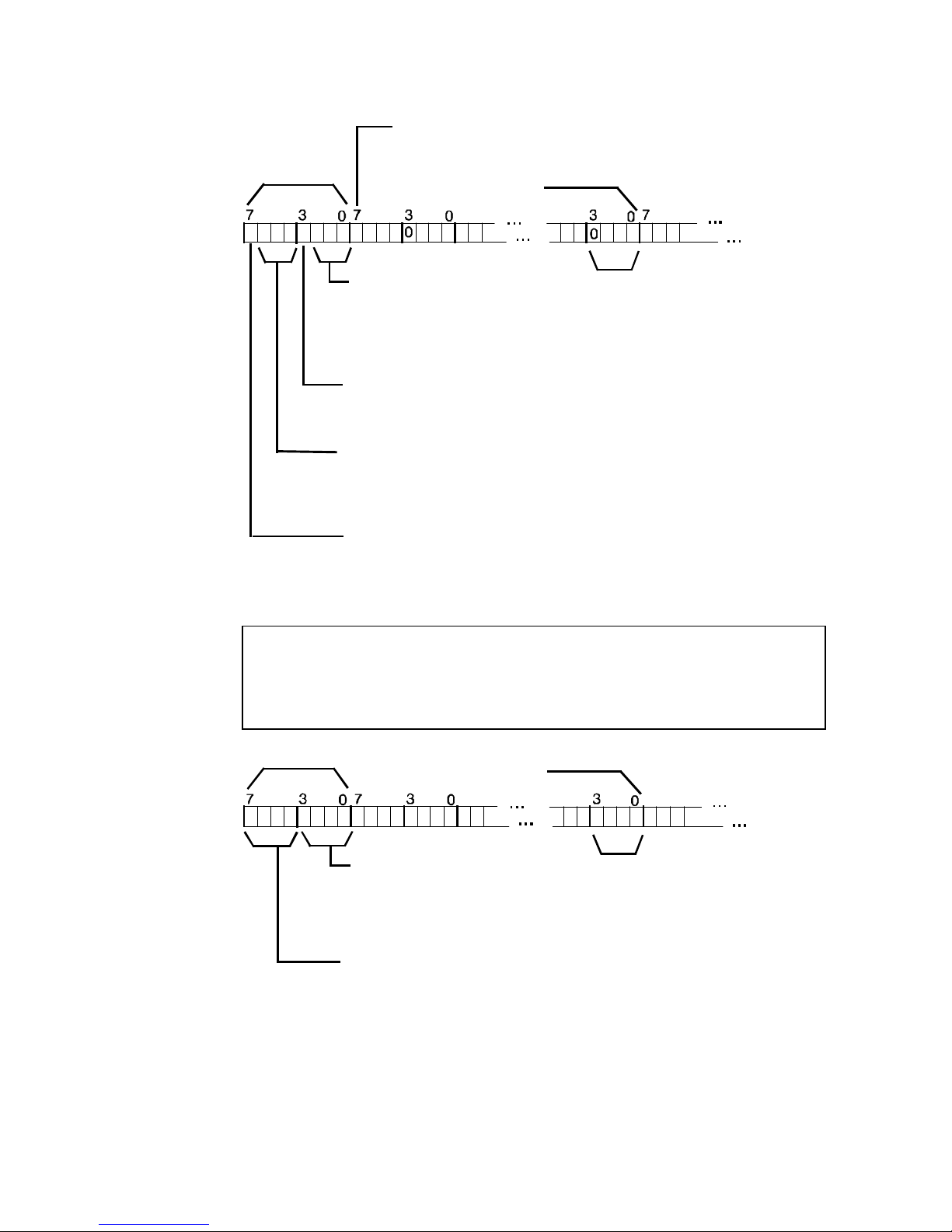
The Chassis MIB 3-9
Figure 3-2. uchasFrontPanelLedStates
NOTE: The most significant bits of the first 3 nibbles for each
card are used as outlined above. The most significant bits of the
remaining 9 nibbles for each card are reserved and currently
always set to zero.
Figure 3-3. uchasFrontPanelLedColor
Page 46

3-10 Using Total Control MIBs
Known Types
Under the uchasKnownTypes sub-tree of the chassis MIB are a
number of OID (object ID) definitions to be used as values within
objects of the chassis MIB. OIDs defined under
uchasKnownModules are NAC identifiers used as values for
uchasSlotModuleType in the slot table. OIDs defined under
uchasKnownEntities are to be used as values for
uchasEntityObjectID in the entity table.
Chassis Commands
uchasCmdTable
A general description of the basic concepts of all command tables is
found earlier under Command Tables. This section contains
information specific to the chassis command table.
This table is indexed by slot number. It contains commands that
are common to all cards and are activated at the slot level. The
following describes the commands available from this table.
uchasCmdTable Command Descriptions
Command Description
noCommand(1) This is the default value for uchasCmdFunction.
Setting uchasCmdFunction to this value will
abort any command that is currently in
progress.
removeFromService(2) Not supported in the MP/16.
restoreToService(3) Not supported in the MP/16.
hardwareReset(4) In a situation where the software level reset
command is not sufficient, the Network
Manager may resort to this command to restore
functionality to a device. Performs a hardware
level reset to a specific modem channel in the
selected modem module (slot number), as
defined by the Param object of the
uchasCmdTable. The value for this parameter
must be an ascii character ‘1–8’ (Hex 31–38).
See Command Tables at the beginning of this
section.
Page 47

The Chassis MIB 3-11
Command Description
softwareDownload(5) Software download is a very important feature to
the Network Manager. It allows the firmware on
the management or modem modules to be
upgraded for feature enhancements and bug
fixes. The software download process is nontrivial due to the coordinated series of SNMP
operations together with one or two TFTP file
transfers. Once the steps are understood,
however, implementation on the management
station is straightforward.
Software Download to the Modem Modules
The softwareDownload(5) command from the uchasCmdTable
allows you to perform a software download to all the modem
channels in one or both modem modules simultaneously. When
these commands are executed (i.e., by using the SNMP SET
request) each slot selected is put into a software downloa d state,
essentially rendering them active only for purposes of SDL.
Querying the uchasCmdTable rows for the affected slots (i.e., by
using the SNMP GET request) should result in an inProgress(3)
status in the uchasCmdResult column for the appropriate rows;
this indicates successful command initiation on these slots. Once
the uchasCmdFunction object is SET to softwareDownload(5), the
management station must begin the next step. Failure to do so will
result in the devices aborting the software download.
The next step involves transferring the .SDL file from the MS to the
management module. The following is an example of how this
might be done :
TFTP -B PF010100.SDL
192.77.203.65=PF010100.SDL
This is an example of the Novell LAN Workplace TFTP application
syntax for downloading binary file PF010100 to the MP/16
management module with IP address 192.77.203.65. The
PF010100.SDL file represents the local file while the filename after
the "=" refers to the destination file. The destination file must
either have an extension of .sdl (case insensitive) or the filename
must be SDL (compatible with earlier versions of NMC software).
If a TFTP write session is available on the MP/16, it will send the
trigger request to each slot involved in the software download.
This places the modem modules in the software download state
and allows the management module to receive the card I D of the
Page 48

3-12 Using Total Control MIBs
modem modules (which the management module uses for .SDL file
validation). The file transfer begins by transferring the .SDL file in
a series of 512 byte packets. The first packet contains the .SDL file
32-byte header that the management module uses to validate the
software download. If the validation is successful, subsequent
TFTP data packets are transferred.
NOTE: If a software download fails or is aborted, wait for one
minute before attempting another download. This waiting period
allows the devices to exhaust their timeouts before beginning a
new SDL procedure.
When the TFTP transfer is completed without error, the MS should
poll the uchasCmdCode object in the uchasCmdTable for the slots
involved in the software download. All modules involved in the
software download are erasing their Flash ROM at this time; the
MS must wait until all modules complete this before beginning the
.NAC file transfer. When all slots undergoing software download
have a uchasCmdCode value of downloadingNACFile(82) (i.e., all
modules have successfully erased their Flash), the .NAC file TFTP
transfer may be initiated. The management station must begin the
TFTP transfer of the .NAC file. Failure to do so will result in the
devices aborting the software download.
As an example, the following TFTP command (or its equivalent) is
issued to download the .NAC file to the management module:
TFTP -B PF010000.NAC
192.77.203.65=PF010000.NAC
The first TFTP data packet carries the .NAC file’s header, which the
NMC uses, again, to validate the .NAC file. If the validation
passes, subsequent data packets are sent until the entire .NAC file
is transferred. At this point, the MS may poll the uchasCmdResult
in the uchasCmdTable for the slots involved in the software
download. The success(2) value should be present in these rows.
The NAC software download is complete.
Software Download to the NMC
Software download to the NMC involves a different mechanism
since a large portion of NMC operational code must remain
running in order to support the SDL transport. When instructed to
enter SDL, all other devices use a loader (located in the device’s
Flash ROM boot block), which is in charge of supporting the .SDL
file transfer. In these cases, the operational code is not running on
Page 49

The Chassis MIB 3-13
the device. Because the NMC needs to support the TFTP protocol
and, as a result, the entire IP stack, a large portion of the NMC’s
operational code remains running. Moreover, the SDL
functionality is built int o the NMC’s operational code. In this way,
SNMP-initiated SDLs need not transfer an .SDL file when NMC
SDL is triggered.
Initiating NMC SDL is performed in the same manner as for
NACs—by setting the uchasCmdFunction in the uchasCmdTable
to softwareDownload(5) for slot 3. This places the NMC in an SDL
state. As a result, all subsequent SNMP agent operation is
suspended, and any incoming SNMP GET or SET requests are
immediately turned around and sent back as GET responses with a
generic error.
Executing the SDL command forces the NMC to erase its Flash
ROM. During this time, the SNMP error-status object (in response
to incoming requests) is set to 125, meaning the NMC is in an SDL
state and is erasing its Flash. Once the Flash is erased, the NMC
changes SDL state, forcing subsequent SNMP requests to be
returned with error-status objects set to 124. This is the MS’s
trigger to begin the .NAC file transfer.
The following TFTP command is issued to download the .NAC file
to the NMC:
TFTP -B NM020200.NAC
192.77.203.65=NM020200.NAC
The first TFTP data packet carries the .NAC file’s header, which the
NMC uses to validate the .NAC file. If the validation passes,
subsequent data packets are sent until the entire .NAC file is
transferred. After a complete successful .NAC file transfer, the MS
should wait for the NMC to reboot and become operational with
the newly downloaded code. If the .NAC file transfer is
unsuccessful and the TFTP transfer is aborted, the NMC will
remain in the “waiting for SD L” mode (blinking green Run/Fail
LED). After waiting for the NMC to re-erase its Flash ROM, the
MS may re-initiate the TFTP transfer.
There is no need to re-issue the softwareDownload(5) command. If
the MS must verify that the NMC has finished erasing Flash and is
waiting for SD L, it may issue any SNMP request and match the
124 generic error code in the corresponding response.
Note that once the NMC has erased its operational software from
the Flash devices, the NMC's network protocol stack exists only in
RAM. Power cycling the NMC at this point means that the NMC
Page 50

3-14 Using Total Control MIBs
will only be able to power up in a “waiting for SDL” mode on its
local console port via the PCSDL.EXE mechanism.
Enabling Chassis Traps
Each of the chassis-level traps has an associated enable object. If
one of these objects is SET to disabled, the proxy agent will not
send traps for that event. SETting one of these objects to enabled
allows the proxy agent to send traps for the associated event. Even
though there are some slot and entity related traps found here,
there is only a single enable for these traps. In order for the NMC
to actually send traps, one or more entries must exist in the trap
destination table in the NMC MIB. See the section titled The Trap
Destination Table later in this document for further details.
The NMC MIB
Although the MP/16 management module can not be accurately
termed an “NMC,” it uses the Total Control NMC MIB, as it
behaves identically in respect to its implementation of applicable
NMC MIB variables. To remain consistent with NMC MIB table
entries and extensions, the MP/16 management module should be
thought of as the NMC when applying MIBs to the MP/16.
Internet ID
iso.org.dod.internet.private.enterprises.usr.nas.nmc =
1.3.6.1.4.1.429.1.2
NMC-Specific Configuration
Changes to read-write objects found under nmcCfg take effect
immediately upon issuance of the SNMP SET request. Changes to
these objects are made permanent by issuing the saveToNvram
command (see section on NMC Commands). When the NMC
boots from power on or a software reset command, the NMC
always initializes these variables from the values that have last
been saved to the NMC's NVRAM.
Configurable objects found under nmcCfg that are not discussed
below are self-explanatory given the MIB text.
Page 51

The NMC MIB 3-15
The NMC's Real-Time Clock
Before setting the NMC's real time clock, it is important to tell the
NMC what time zone it is in to aid in converting times between
local time and Greenwich Mean Time (GMT). This is done by
setting nmcTimezone to the appropriate value. Similarly, the NMC
must be configured as to whether or not to honor daylight savings
time by setting nmcDaySavingTime. With these having been set,
values for nmcCfgSystemTime and nmcCfgSystemDate can be
configured. Both the time and date objects should be set according
to the local time of the NMC's physical location.
The format for the time string is HH:MM:SS where . . .
HH=Hours (0-23)
MM=Minutes (0-59)
and SS=Seconds (0-59)
The format for the date string is MM/DD/YY where . . .
MM=Month (1-12)
DD=Day(1-31)
and YY=Year
An accurate setting of the NMC's real time clock is important if the
Network Manager wants good timestamps in the SNMP Trap
messages sent by the proxy agent. Traps contain a timestamp in
Greenwich Mean Time as an integer indicating the number of
seconds since midnight on January 1, 1970.
Configuring the Console Port for Dial Access
If the Console port is directly connected to the serial port of the
management station, configuration of these objects is probably of
no consequence. However, if the Console port is physically
connected to a modem for dial up access, the following paragraphs
are important.
Whenever the NMC has a SLIP packet that it wishes to transmit
out the Console port, the NMC checks for the presence of Carrier
Detect (CD) on the Console port serial interface. If CD is present, it
is assumed that a connection to the desired destination exists and
the packet is then transmitted. Using a null modem adapter and
directly connecting the WAN port to the DTE port of a
management station results in the management station's Data
Terminal Ready (DTR) signal driving CD, so typically the NMC
sees CD present if directly connected.
Page 52

3-16 Using Total Control MIBs
If the NMC is trying to transmit a packet out the Console port and
it doesn't detect the presence of CD, it attempts to set up a modem
on that port by issuing the AT command that the user has
configured via nmcCfgAtString.
Note that the default value of nmcCfgAtString is:
AT&FE0Q0&H1&R2&B1V1
This enables command mode local echo, verbal result codes, and
hardware flow control. These settings should be maintained for
proper functionality with the modem, but if other additional
settings are desired, they can be added to this string.
Next, the NMC proceeds to issue an AT dial command using the
phone number configured in nmcCfgWanDialOutPhoneNum. If
the process of dialing results in a successful connection (i.e., CD
becomes active), the packet is transmitted. If at least one packet is
received and/or transmitted every 60 seconds while an NMCinitiated dial connection is up, the modems remain on-line, but if 60
seconds goes by without any SLIP traffic on the Console port, the
NMC drops DTR and hangs up the call.
NOTE: On a dial-in call to the NMC, this idle time restriction
does not exist.
In the event that the NMC is not successful in making a dial-up
connection while attempting to transmit a packet from the Console
port, the NMC waits the number of seconds specified by
nmcCfgWanRetryPause (default=20 seconds) and retries the dialed
number. The NMC retries up to the number of times specified by
nmcCfgNumWanRetries before it gives up. If the number of retries
is exceeded, the NMC discards the packet it was trying to transmit.
If nmcCfgNumWanRetries is 0, the NMC tries to send that packet
forever and will not discard it.
Each unsuccessful dial attempt is counted by the NMC as a
connection attempt failure. If the number of connection attempt
failures exceeds the value configured in
nmcCfgNumFailBefSuspend (default=3), the NMC suspends dial
out attempts for the time specified by the value configured in
nmcCfgWanRetrySuspendTime (default=5 min). The purpose for
suspending such dial out attempts is to allow remote management
stations to dial in to the Console port. For example, if the remote
line is always busy and the NMC continuously tries to dial out,
remote management stations may be unable to dial in. Upon the
Page 53

The NMC MIB 3-17
suspension timer expiration, the NMC may continue to make dial
out connections subject to further suspensions by the same rules.
NOTE: The values for nmcCfgAtString and
nmcCfgWanDialOutPhoneNum can be modified to connect the
WAN port to other devices, such as an X.25 PAD.
NMC Status Information
Most of the objects in the nmcStat group are self-explanatory, with
the exception of the NMC test result bitmaps. Because the NMC's
online test results do not fit nicely into the result mechanism for
commands, they are returned in a separate object,
nmcStatTestResult. This object should be retrieved by a single GET
request together with nmcCmdResult, nmcCmdCode,
nmcCmdMgtStationId, and nmcCmdReqId to ensure that results
retrieved were those generated by a given management station.
(See the discussion of command tables in the section titled
Command Tables.)
The results of the NMC's power on self tests are returned in a
similar bit-mapped object called nmcStatPowerUpTstFailBMap.
The definitions for both nmcStatTestResult and
nmcStatPowerUpTstFailBMap consists of INTEGERs. An
INTEGER 1 in the bit map indicates test failure. If the bits are
numbered such that 1 is the least significant bit of the integer and
32 is the most significant bit, the bit definitions are as follows.
Page 54

3-18 Using Total Control MIBs
Bit Number Test Name
0 Management Bus UART #1
1 Management Bus UART #2
2 Console/WAN port UART
3 Manufacturing NVRAM CRC
4 MP/16 Device Configuration NVRAM CRC
5 Ethernet Interface hardware
Failure of one or more power up tests results in the NMC blinking
its Run/Fail LED alternately green and then red. If all power up
tests pass, the NMC Run/Fail LED remains solid green.
The object nmcStatCompSwVer is used by the Total Control
Manager software to identify MIB compatibility, independent of
NMC and TCM software versions. If two different versions of
NMC software return the same value for nmcStatCompSwVer,
then they both implement the same MIBs. As new NMC software
is developed, every effort is made to ensure backward
compatibility with prior MIB versions. This means that if NMC #1
has the a larger value for nmcStatCompSwVer than that of NMC
#2, then NMC #1's MIB support is a superset of that of NMC #2.
The Trap Destination Table
In order for the NMC to generate a trap, the corresponding trap
enable object must be set to enable. In addition, at least one entry
must be present in the nmcTrapDestTable. In order to create a row
in this table, the management station must issue an SNMP SET
request on nmcTrapDestCommunity to a value other than Invalid.
The index used to issue the SET should be the IP address of the
destination management station. SETting the community string for
an existing row to the value of Invalid results in deletion of the
specified row from the trap destination table. An optional
destination description object is available for the convenience of the
management station, but is not required for proper operation of the
trap mechanism. Upon generation of a trap, the TRAP PDU is sent
to all management stations in the trap destination table.
Page 55

The NMC MIB 3-19
NMC Commands
Configuration-related Commands
Before discussing each of the configuration-related NMC
commands, there are a number of items that need to be addressed.
First is the issue of NVRAM. Each NAC has its own NVRAM. In
addition, the NMC has its own NVRAM. The two are completely
independent.
Here are two basic ways that the Network Manager might use the
NVRAM in the chassis.
♦ Configure each device and save the settings to each NAC's
NVRAM. Set those NACs to boot from their own NVRAM
(ignoring the NMC NVRAM, except for NMC-specific
parameters). Disable the parameter
nmcPowerUpAutoCfgEnable so the NMC does not
automatically configure the NACs, either upon install of the
NAC, install of the NMC, or power up of the chassis.
♦ Configure each device and save all settings to the NMC's
NVRAM (ignoring each NAC's NVRAM). Enable
nmcPowerUpAutoCfgEnable so the NMC automatically
configures each device upon install of the NAC, install of the
NMC, or power up of the chassis.
The advantage of the first approach is that it minimizes the effort of
the NMC. However, it also opens up the possibility of local
configuration changes that the NMC does not know about. Some
of this can be minimized, for example by disabling configurationrelated AT commands on the modems.
Because of the difficulties associated with attempting to keep the
NMC in sync with configuration changes that are made via local
interfaces on the various NACs, the concept of a configuration
cache was born in the NMC. This cache operates as follows.
1 Upon power up, as the NMC begins discovering cards in the
chassis, the NMC loads the cache for each of the sixteen slots
from the values previously saved in NVRAM.
2 The cache values for any slots for which there is no
configuration in the NMC's NVRAM are set to defaults.
Page 56

3-20 Using Total Control MIBs
3 From this point on, as SNMP SETs are made to devices
through the NMC's proxy agent, the cache for that slot is
updated with the change. The values in the cache are saved in
the NMC's NVRAM upon the invocation of a saveToNvram(2)
command. These are the values that are used by the NMC in
doing an autoconfigure operation.
None of the NMC's configuration parameters are cached like the
NAC-specific parameters. They are always restored from the
NMC's NVRAM. The MIB objects defined under nmcUiCfg are
also not cached and never saved to NVRAM. A separate storage
facility in the NMC's EEPROM is provided for these settings.
NMC Configuration Command Descriptions
Command Description
noCommand(1) This is the default value for nmcCmdFunction.
Setting nmcCmdFunction to this value will abort
any command that is currently in progress.
saveToNvram(2) This command saves the current configuration
cache contents for the device in each slot to
Flash NVRAM on the NMC. In addition, it saves
the current state of each of the NMC's
configurable parameters. The exception to this is
the parameters that are part of the nmcUiCfg
group. These are the same parameters that are
configurable from the NMC's local console serial
port. These parameters are saved to EEPROM
by a separate NMC command (see
saveUiParamsToEEPROM below).
restoreFromDefaults(3) With the exception of the nmcUiCfg group, all
other configurable NMC parameters are restored
to their default state by this command. In
addition, this command restores the cache for
each slot to the default values for the given card
type. After defaulting the cache, the cache
contents are used to reconfigure each device to
the default state. For the most part, this
command restores the entire chassis to the
factory default configuration, with the exception
of the IP addresses, etc., of the nmcUiCfg group,
which are treated separately.
Page 57

The NMC MIB 3-21
Command Description
restoreFromNvram(4) With the exception of the nmcUiCfg group, this
command restores all configurable NMC parameters
to the value last saved to the NMC's NVRAM. In
addition, an attempt is made to restore the cache for
each slot to the values that were last saved to the
NMC's NVRAM. If the parameters in NVRAM for a
given slot do not match the card type that is currently
installed in that slot, the cache for that slot is loaded
from the default values for the given card type. After
restoring all of the slot caches, the NMC proceeds to
configure each device with the parameter values from
that slot's cache.
nonDisruptSelfTest(5) Upon power up, the NMC does a full hardware self-
test. Once the NMC is running operational code,
such a test would disrupt the NMC's ability to perform
certain network management functions. For this
reason, the online version of the NMC's self test is
non-disruptive, comprised of a subset of the power up
tests. For convenience, the test results are returned
in a bit-mapped object (nmcStatTestResult) that is
defined exactly like the power on self test result
(nmcStatPowerUpTstFailBMap). The example below
identifies which tests (and bits) pertain to the NMC's
non disruptive self test (assuming that the least
significant bit of the INTEGER bit map is bit #1 and
the most significant is bit #32).
Bit Number Test Name
18 Analog to Digital Converter
19 EEPROM CRC (other
manufacturer's information)
20 Flash Vpp Programming Voltage
21 Power Supply Presence Circuit
22 Flash File System CRC Test
softwareReset(6) Provides the ability to reset the NMC from a remote
location. This may be useful when changing the IP
addressing of an NMC or in an emergency situation
where some sort of NMC software malfunction is
encountered and the Network Manager needs to
restore the NMC to a good state.
Page 58

3-22 Using Total Control MIBs
Command Description
saveUiParamsTo
EEPROM(7)
This command is used to save the values of the MIB
objects defined in the nmcUiCfg group of the NMC
MIB to the EEPROM on the NMC. These objects are
treated separately from the other configurable
parameters of the NMC for a couple of reasons.
One such reason is that the IP addressing of the
NMC is unique. For this reason, it makes sense to
store them in the EEPROM that is physically part of
the NMC board. The Flash SIMM can easily be
swapped with other NMCs. Similarly, USR's Total
Control Manager/SNMP Console software does not
save this group of parameters in the *.whb file when
it saves a chassis configuration to disk.
The reason this command is necessary is that none
of the IP addressing parameters take effect
immediately upon issuing the SNMP SET request.
The new values are simply stored in RAM. Then
upon issuing the saveUiParamsToEEPROM
command, the NMC saves the RAM image to
EEPROM. Subsequently, a softwareReset
command must be issued to the NMC to cause the
new values for IP address related objects to take
effect.
MIB Access to Local Console Port
Configuration Parameters
For the convenience of remote management of the NMC, MIB
access has been provided to the configurable parameters of the
local console serial port. These parameters include such things as
IP addresses, subnet masks, SNMP community strings, etc. Due to
the complexities associated with changing many of these
parameters while the NMC is running operational code, an SNMP
SET to most of these objects simply results in setting a RAM
location within the NMC. A subsequent saveUiParamsToEEPROM
command must be issued, followed by a softwareReset command
or power cycle in order for the new values to take effect.
The exception to this rule is with the SNMP community strings.
Both the public (read-only view) and private (read-write view)
community strings take effect immediately, but if the NMC is reset
without issuing a saveUiParamsToEEPROM command, they will
revert to the values last saved to EEPROM.
Page 59

The NMC MIB 3-23
NMC Authorized Access List
By default, the NMC authorized access table is empty. In this state,
there is no restriction on which management stations may manage
the chassis. Once a row is added to the authorized access table,
only management stations whose IP addresses pass the
authorization validation against the table are permitted access to
the NMC for the purposes of network management.
The table is indexed by IP address (nmcAuthAccIpAddr). The
other objects in each row include a required subnet mask
(nmcAuthAccNetMask) and optional textual description
(nmcAuthAccDescr). To add a row, simply set a value other than
0.0.0.0 for nmcAuthAccNetMask with the desired index.
If the Network Manager wishes, set a description in
nmcAuthAccDescr to describe the access allowed by the given row.
To delete the row, simply set nmcAuthAccNetMask to 0.0.0.0.
Note that a maximum of 10 rows may be added to this table.
The NMC performs IP address authorization validation by the
process described below.
1 Take the source IP address of the inc oming IP packet and
perform an "and" operation on it and the value of
nmcAuthAccNetMask for the first row in the authorized access
list.
2 Compare this "anded" value with the value obtained by
performing an "and" on the nmcAuthAccIpAddr with
nmcAuthAccNetMask for the same row.
♦ If the two values match, the IP packet passes the
authorization test and is passed to higher protocol layers
for further processing.
♦ If the values do not match, the next row in the authorized
access list is verified by the same procedure listed above.
If the end of the table is reached without a match, the IP
packet fails the authorization test and it is discarded. The
value of ipInDiscards is incremented and the IP packet is
discarded.
ICMP packets are not validated against the above checks for the
Network Manager’s convenience. It is often helpful to use an
ICMP echo packet to check basic network health from any
Page 60

3-24 Using Total Control MIBs
convenient network terminal. All SNMP and TFTP packets are
checked against this authorization list.
The Network Manager may clear the authorized access list from
the local console port in the event that access is locked (i.e., the
management station is not listed in the access list). Alternatively,
the boot from defaults DIP switch (5) can be used to boot with an
empty access list (i.e., no restrictions).
Accounting/Event Logging Server
The U.S. Robotics Accounting and Event Logging application
captures and logs a wide variety of call accounting and event
logging information to simple ASCII log files. Like the Security
option, this feature relies on the RADIUS (Remote Authentication
Dial In User Service) client-server protocol.
The NMC client communicates with the PC-based server via
Ethernet or Token Ring IP LAN. Information such as modem
connectivity and specific chassis events may be sent by NMC
clients across a LAN connection to be logged. The server itself
does not generate reports from the data; a post-processing
application or database script must be used to format the logged
data.
NOTE: We do not encourage sending log data to a server via a
WAN connection.
There are a number of accounting and event logging-related
parameters in the nmcCfgLog and nmcTeLog groups of the NMC
MIB. These include configurable server selections and a trap for
any loss of server connection. The MIB text associated with each
object is self-explanatory.
Log Records
The NMC client can receive event records from 65 possible sources.
This corresponds to the NMC manager task and each instance of
the 16 device manager tasks times 4. The NMC client has an input
queue capable of handling 65 event records. This allows for the
maximum possible requesters to be issuing event records
simultaneously. If the input queue of the NMC client becomes
overloaded, the requester’s attempt to issue an event record will be
rejected. It is up to the requester to handle these rejections.
Initially, the events are discarded.
Page 61

The NMC MIB 3-25
The NMC client removes an event record from its input queue,
formats it properly for the RADIUS server, sends it, and waits for
the reply before starting on the next event record. If the NMC
client is unable to communicate with a RADIUS server, the NMC
client discards the event records.
Event Log
The event record format may be extended to include the necessary
event information. The following information is included with all
event records.
♦ IP Address of Chassis
♦ UDP Port Number
♦ Event Sequence Number
♦ Event Identifier
♦ Event Date/Time Stamp
The following table identifies the information sent in the log record
for each event, in addition to the standard fields listed above. The
Generic Slot Record consists of the Slot Number and Module Type.
The Entity Index indicates a description beyond slot, e.g., modem
channel.
Page 62

3-26 Using Total Control MIBs
Events
Additional Information
In Event Record
Module Watchdog Time-out (12) Generic Slot Record
Management Bus Failure (13) Generic Slot Record
Entity Index
Incoming Connection Established (14) Generic Slot Record
Call status
Entity Index
Outgoing Connection Established (15) Generic Slot Record
Call status
Entity Index
Incoming Connection Terminated (16) See following description
Outgoing Connection Terminated (17) See following description
Connection Attempt Failed (18) Generic Slot Record
Entity Index
Failure to connect reason
Connection Time Limit Expired (19) Generic Slot Record
Entity Index
Connect time limit
DTE Transmit Idle (20) Generic Slot Record
Entity Index
DTE Data Idle Timeout
DTR True (21) Generic Slot Record
Entity Index
DTR True Timeout
DTR False (22) Generic Slot Record
Entity Index
DTR False Timeout
Block Error Count at Threshold (23) Generic Slot Record
Entity Index
Block Error Count Limit
Fallback Count at Threshold (24) Generic Slot Record
Entity Index
Fallback Count Limit
No Dial Tone Detected (25) Generic Slot Record
Entity Index
No Loop Current Detected (26) Generic Slot Record
Entity Index
Modem Reset by DTE (32) Generic Slot Record
Entity Index
Modem Ring No Answer (33) Generic Slot Record
Entity Index
Ring No Answer Limit
DTE Ring No Answer (34) Generic Slot Record
Entity Index
Ring No Answer Limit
Page 63

The NMC MIB 3-27
Connection Log
Event Records for Incoming Connection Terminated (16) and
Outgoing Connection Terminated (17) are identical, except as noted
in the table below (ANI, Number Dialed, and DNIS in Group 1).
Incoming Connection
Terminated (16)
and
Outgoing Connection
Terminated (17)
Generic Slot Record
Entity Index
Usage Statistics (Group 1 - always sent):
User Name (mdmCsSecurityUserName)
Call Start Date/Time
Call End Date/Time
Call Termination Reason (mdmCsDisconnectReason)
ANI (mdmCsLastCallingPartyNum)--INCOMING ONLY
Number Dialed (mdmCsLastNumberDialedOut)--OUTGOING ONLY
DNIS (mdmCsLastNumberDialedIn)--INCOMING ONLY
Call Duration (mdmCsCallDuration)
Data Transfer Statistics (Group 2):
Characters Sent (mdmCsCharsSent)
Characters Received (mdmCsCharsReceived)
Octets Sent (mdmCsOctetsSent)
Octets Received (mdmCsOctetsReceived)
Blocks Sent (mdmCsBlocksSent)
Blocks Received (mdmCsBlocksReceived)
Blocks Resent (mdmCsBlocksResent)
Characters Lost (mdmCsCharsLost)
Line Reversals (mdmCsLineReversalQty)
Performance Statistics (Group 3):
Block CRC Errors (mdmCsBlerQty)
Link NAKs (mdmCsLinkNakQty)
Link Fallbacks (mdmCsFallbackQty)
Link Upshifts (mdmCsUpshiftQty)
Link Timeouts (mdmCsLinkTimeoutQty)
Initial Link TX Rate (mdmCsInitialTxLinkRate)
Final Link TX Rate (mdmCsFinalTxLinkRate)
Initial Link RX Rate (mdmCsInitialRxLinkRate)
Final Link RX Rate (mdmCsFinalRxLinkRate)
Retrains Requested (mdmCsRetrainsRequested)
Retrains Granted (mdmCsRetrainsGranted)
Operating Mode Statistics (Group 4):
Sync/Async Mode (mdmCsSyncAsyncModeUsed)
Modulation Type (mdmCsModulationType)
Originate/Answer Mode (mdmCsOriginateAnswer)
Error Control Type (mdmCsErrorControlType)
Data Compression Type (mdmCsCompressionType)
HST Back Channel Rate (mdmCsBackChannelRate)
Default DTE Data Rate
High Freq Equalization (mdmCsEqualizationType)
On-Line Fallback (mdmCsFallbackEnabled)
Attribute/Data Type Descriptions
The following pages contain these tables:
Page 64

3-28 Using Total Control MIBs
Table 3-2. Log Message RADIUS Attributes and Data Types
(Attribute Values 1-26)
Table 3-3. Log Message RADIUS Attributes and Data Types
(Attribute Values 40-46)
Table 3-4. U.S. Robotics Vendor Specific Attributes and Data Types
per Event Type (Event IDs 06 through 21)
Table 3-5. U.S. Robotics Vendor Specific Attributes and Data Types
per Event Type (Event IDs 06 through 21)
Table 3-2. Log Message RADIUS Attributes and Data Types (Values 1-26)
RADIUS Attributes (Value) and Data Types
U.S. Robotics Event
Event
ID
User
Name
(1)
Client
ID
(4)
Client
Port ID
(5)
Dial
Back No.
(19)
Vendor
Spec.
(26)
Watchdog Timeout 12 S,A S,I S,V
Management Bus Failure 13 S,A S,I S,V
Incoming Connection Est. 14 S,A S,I S,V
Outgoing Connection Est. 15 S,A S,I S,V
Incoming Connection Term. 16 S,C S,A S,I S,C S,V
Outgoing Connection Term. 17 S,C S,A S,I S,V
Connection Attempt Failure 18 S,A S,I S,V
Connection Timer Expired 19 S,A S,I S,V
DTE Transmit Data Idle 20 S,A S,I S,V
DTR True 21 S,A S,I S,V
DTR False 22 S,A S,I S,V
BLER Count at Threshold 23 S,A S,I S,V
Fallback Count at Threshold 24 S,A S,I S,V
No Dial Tone 25 S,A S,I S,V
No Loop Current 26 S,A S,I S,V
Modem Reset By DTE 32 S,A S,I S,V
Modem Ring No Answer 33 S,A S,I S,V
DTE Ring No Answer 34 S,A S,I S,V
S = Standard
O = Optional. Part of Call Termination statistics group n.
Data Types: A = IP Address, I = Integer, C = Character String, T = GMT date/time,
V = Variable (see Vendor Specific attribute table).
Page 65

The NMC MIB 3-29
Table 3-3. Log Message RADIUS Attributes and Data Types (Values 40-46)
USR Event
Acct.
Status
Type
(40)
Acct.
Input
Octets
(42)
Acct.
Output
Octets
(43)
Acct.
Sess.
ID
(44)
Acct.
Sess.
Time
(46)
Watchdog Timeout S,I
Management Bus Failure S,I
Incoming Connection Est. S,I S,I
Outgoing Connection Est. S,I S,I
Incoming Connection Term. S,I O2,I O2,I S,I S,I
Outgoing Connection Term. S,I O2,I O2,I S,I S,I
Connection Attempt Failure S,I
Connection Timer Expired S,I
DTE Transmit Data Idle S,I
DTR True S,I
DTR False S,I
BLER Count at Threshold S,I
Fallback Count at Threshold S,I
No Dial Tone S,I
No Loop Current S,I
Modem Reset By DTE S,I
Modem Ring No Answer S,I
DTE Ring No Answer S,I S,I
S = Standard
O = Optional. Part of Call Termination statistics group n.
Data Types: A = IP Address, I = Integer, C = Character String, T = GMT date/time,
V = Variable (see Vendor Specific attribute table).
Page 66

3-30 Using Total Control MIBs
Table 3-4. USR Vendor Specific Attributes and Data Types
per Event Type (Event IDs 12 through 21)
USR Event IDs
USR Attribute
Attr.
Value
Data
Type 12 13 14 15 16 17 18 19 20 21
DTE-Data-Idle-Timout 0x0048 I S
Default-DTE-Data-Rate 0x005E I O4 O4
Last-Number-Dialed-Out 0x0066 C S
Sync-Async-Mode 0x0067 I O4 O4
Originate-Answer-Mode 0x0068 I O4 O4
Failure-to-Connect-Reason 0x0069 I S
Initial-Tx-Link-Data-Rate 0x006A I O3 O3
Final-Tx-Link-Data-Rate 0x006B I O3 O3
Modulation-Type 0x006C I O4 O4
Equalization-Type 0x006F I O4 O4
Fallback-Enabled 0x0070 I O4 O4
Characters-Sent 0x0071 I O2 O2
Characters-Received 0x0072 I O2 O2
Blocks-Sent 0x0075 I O2 O2
Blocks-Received 0x0076 I O2 O2
Blocks-Resent 0x0077 I O2 O2
Retrains-Requested 0x0078 I O3 O3
Retrains-Granted 0x0079 I O3 O3
Line-Reversals 0x007A I O2 O2
Number-Of-Characters-Lost 0x007B I O2 O2
Back-Channel-Data-Rate 0x007C I O4 O4
Number-of-Blers 0x007D I O3 O3
Number-of-Link-Timeouts 0x007E I O3 O3
Number-of-Fallbacks 0x007F I O3 O3
Number-of-Upshifts 0x0080 I O3 O3
Number-of-Link-NAKs 0x0081 I O3 O3
Simplified-MNP-Levels 0x0099 I O4 O4
Connect-Term-Reason 0x009B I S S
DTR-False-Timeout 0x00BE I
Fallback-Limit 0x00BF I
Block-Error-Count-Limit 0x00C0 I
Simplified-V42bis-Usage 0x00C7 I O4 O4
On = Optional. Part of Call Termination statistics group n.
S = Standard
Data Types: C = Character String, I = Integer, T = GMT date/time
Table 3-4. (Continued)
Page 67

The NMC MIB 3-31
USR Event IDs
USR Attribute
Attr.
Value
Data
Type 12 13 14 15 16 17 18 19 20 21
DTR-True-Timeout 0x00DA I S
Last-Number-Dialed-In-
DNIS
0x00E8 C S
Last-Callers-Number-ANI 0x00E9 C S
Card-Type 0xBE85 I
DTE-Ring-No-Answer-
Limit
0xBF17 I
Final-Rx-Link-Data-Rate 0xBF2C I O3 O3
Initial-Rx-Link-Data-Rate 0xBF2D I O3 O3
Event-Date-Time 0xBF2F T S S S S S S S S S S
Channel 0xBF38 I S S S S S S S S S S
Chassis-Slot 0xBF39 I S S S S S S S S S S
Event-Id 0xBFBE I S S S S S S S S S S
Number-of-Rings-Limit 0xBFE6 I
Connect-Time-Limit 0xBFE7 I S
Call-End-Date-Time 0xBFF6 T S S
Call-Start-Date-Time 0xBFF7 T S S
On = Optional. Part of Call Termination statistics group n.
S = Standard
Data Types: C = Character String, I = Integer, T = GMT date/time
Page 68

3-32 Using Total Control MIBs
Table 3-5. USR Vendor Specific Attributes and Data Types per Event Type
(Event IDs 22 through 34)
USR Event IDs
USR Attribute
Attr.
Value
Data
Type 22 23 24 25 26 32 33 34
DTE-Data-Idle-Timout 0x0048 I
Default-DTE-Data-Rate 0x005E I
Last-Number-Dialed-Out 0x0066 C
Sync-Async-Mode 0x0067 I
Originate-Answer-Mode 0x0068 I
Failure-to-Connect-Reason 0x0069 I
Initial-Tx-Link-Data-Rate 0x006A I
Final-Tx-Link-Data-Rate 0x006B I
Modulation-Type 0x006C I
Equalization-Type 0x006F I
Fallback-Enabled 0x0070 I
Characters-Sent 0x0071 I
Characters-Received 0x0072 I
Blocks-Sent 0x0075 I
Blocks-Received 0x0076 I
Blocks-Resent 0x0077 I
Retrains-Requested 0x0078 I
Retrains-Granted 0x0079 I
Line-Reversals 0x007A I
Number-Of-Characters-Lost 0x007B I
Back-Channel-Data-Rate 0x007C I
Number-of-Blers 0x007D I
Number-of-Link-Timeouts 0x007E I
Number-of-Fallbacks 0x007F I
Number-of-Upshifts 0x0080 I
Number-of-Link-NAKs 0x0081 I
Simplified-MNP-Levels 0x0099 I
Connect-Term-Reason 0x009B I
DTR-False-Timeout 0x00BE I S
Fallback-Limit 0x00BF I S
Block-Error-Count-Limit 0x00C0 I S
Simplified-V42bis-Usage 0x00C7 I
On = Optional. Part of Call Termination statistics group n.
S = Standard
Data Types: C = Character String, I = Integer, T = GMT date/time
Table 3-5. (Continued)
Page 69

The NMC MIB 3-33
USR Event IDs
USR Attribute
Attr.
Value
Data
Type 22 23 24 25 26 32 33 34
DTR-True-Timeout 0x00DA I
Card-Type 0xBE85 I
DTE-Ring-No-Answer-Limit 0xBF17 I S S
Final-Rx-Link-Data-Rate 0xBF2C I
Initial-Rx-Link-Data-Rate 0xBF2D I
Event-Date-Time 0xBF2F T S S S S S S S S
Channel 0xBF38 I S S S S S S S S
Chassis-Slot 0xBF39 I S S S S S S S S
Event-Id 0xBFBE I S S S S S S S S
Number-of-Rings-Limit 0xBFE6 I
Connect-Time-Limit 0xBFE7 I
Call-End-Date-Time 0xBFF6 T
Call-Start-Date-Time 0xBFF7 T
On = Optional. Part of Call Termination statistics group n.
S = Standard
Data Types: C = Character String, I = Integer, T = GMT date/time
Page 70

3-34 Using Total Control MIBs
The Modem MIB
Internet ID
iso.org.dod.internet.private.enterprises.usr.nas.mdm =
1.3.6.1.4.1.429.1.6
Overview
All tables in the modem MIB are indexed with the entity index of
the entry in the entity table that corresponds to the same modem
(see the Chassis MIB section).
Modem MIB Tables
ID Table
The objects in the mdmIDTable consist of general modem
identification objects. Each of these objects is self-explanatory,
given the MIB text.
Line Interface Table
The objects in the mdmLiTable characterize the operation of the
modem's phone line interface. See the MIB text for a complete
description of each parameter and the relationship of that object to
modem AT commands.
Data Compression Table
The objects in the mdmDcTable define when compression is to be
used. See the MIB text for a complete description of each
parameter and the relationship of that object to modem AT
commands.
Modem Test Table
The objects in the mdmTfTable are for use in conjunction with the
mdmCdTable for performing modem test commands.
Alternatively, the mdmTfTest object, which equates to the S16
register, and the mdmTfV54 object, which equates to the &T n
Page 71

The Modem MIB 3-35
command in the modem, can initiate these commands, but without
the benefits provided by the command table (i.e., mutual exclusion
in the case of multiple management consoles, etc.).
The remainder of the objects in this table are parameters that
provide settings for the tests and results of the V.54 tests.
DTE Interface Table
The objects in the mdmDiTable characterize the operation of the
modem's DTE interface. See the MIB text for a complete
description of each parameter and the relationship of that object to
modem AT commands.
There is one special object in this table. The mdmDiAtString object
is simply a configurable AT command. The intention of this object
is to provide a "backdoor" means to access late breaking modem
features through management if a new modem feature MIB object
has not yet been implemented in the NMC. The NMC can save this
parameter to NVRAM, and will configure this parameter last when
doing an autoconfigure or restore from NMC NVRAM. That
means that if a conflict exists between a MIB object and an AT
command in this string, this string will win out, since it is acted
upon last. Note that all versions of the modem do not support this
object.
Signal Converter Table
The objects in the mdmScTable characterize the operation of the
modem's signal converter. This includes control of allowed
modulation schemes, and specific characteristics for certain
modulations. A number of complex controls are available to tailor
V.Fast and V.34 modulations. See the MIB text for a complete
description of each parameter and the relationship of that object to
modem AT commands.
Call Control Table
The objects in the mdmCcTable characterize the way the modem
sets up and tears down calls. Included here are ANI, DNIS, and
other configurable parameters with regard to a modem's T1
interface. See the MIB text for a complete description of each
parameter and the relationship of that object to modem AT
commands.
Page 72

3-36 Using Total Control MIBs
Error Correction Table
The objects in the mdmEcTable configure the modem's operation
with regard to MNP and V.42 error correction. See the MIB text for
a complete description of each parameter and the relationship of
that object to modem AT commands.
Call Statistics Table
The objects in the mdmCsTable make up a variety of statistics that
pertain to the last or current call for the given modem. When the
modem is not connected, the values are for the last call. Upon
making an incoming or outgoing connection, the values of these
objects are re-initialized and at that time, they reflect the current
call statistics.
Event Counter Table
The objects in the mdmEvTable are initialized to 0 upon installation
or power-on of an NMC, for each modem in the table. From then
on, every time one of the designated events occurs, the
corresponding counter for that modem and event is incremented
by 1. These counters are never zeroed out unless a modem card is
replaced by a non-modem card, and then the non-modem card is
again replaced with a modem card; or if the NMC is power cycled.
These counters can provide useful history information regarding
modem performance.
Event Threshold Table
Many of the modem events defined within the NMC have
associated thresholds. If those thresholds are configurable, they
are found within the mdmEtTable. See the MIB text for a complete
description of each parameter.
Modem Command Table
Only one command is allowed to take place at any one time for a
given modem. If a second command is requested while one is in
progress, an SNMP SET failure will occur. Simultaneous
commands can, however, take place on multiple modems.
Page 73

The Modem MIB 3-37
Modem Command Descriptions
Command Description
noCommand(1) This is the default value for mdmCdFunction. Not
implemented.
softwareReset(2) If the Network Manager wishes to reset a single
modem entity (i.e., one modem on a quad modem
card) without resetting all modems on that card, as
would be the case with the hardwareReset command
in the chassis MIB, he or she may use the software
reset command. If the MP/16 management module
knows that the modem is in a connection or
otherwise in a state such that the Network Manager
may not want to reset the modem, the command
may fail with mdmCdCode value of connected(14).
If the Network Manager wishes to reset the modem
anyway, even though the modem is connected, he
or she may resend the request with the
mdmCdForce set to force. In the event that the
modem is unable to process the softwareReset
command, a hardware reset of the card may be
required.
storeToNvram(3) This command is equivalent to &W of the modem AT
command set. It results in the modem saving all of
its current settings to NVRAM on the modem card.
Each modem entity of a multi-channel modem card
has its own independent NVRAM storage area.
restoreFromDefault(4) This command is equivalent to &F of the modem AT
command set. It restores all of the modem settings
to factory default values.
restoreFromNvram(5) Issuing this command results in the modem
restoring all of its configuration settings to the values
that were last saved to the modem's NVRAM either
by the storeToNvram command on the modem or
the &W command.
offHook(6) This command simply makes the modem go off
hook. It is equivalent to the H1 command. This
command can be used to busy out the phone line.
onHook(7) This command simply makes the modem go on
hook. It is equivalent to the H0 command. This
command can be used to restore the phone line.
loadHwFlowDflt(23)
This command loads the Hardware Flow Control
(&F1) template settings in the modem.
Page 74

3-38 Using Total Control MIBs
Command Description
loadSwFlowDflt(24) This command loads the Software Flow Control
(&F2) template settings in the modem.
loadMnp10CllulrDflt(25) This command loads the MNP10 Cellular (&F4)
template settings in the modem.
loadV42CllulrMblDflt(26) This command loads the V.42 ETC Mobile Cellular
(&F5) template settings in the modem.
loadV42CllulrFxdDflt(27) This command loads the V.42 ETC Fixed Site
Cellular (&F6) template settings in the modem.
hardBusyAtDisable(33) This command is used to busy out the analog
phone line and disable AT commands at the DTE
interface to guarantee that the modem is in an idle
state. Terminates calls in progress when the
command is issued, and forces the modem into an
idle/disabled state. The “status” of the modem as
reported by network management indicates that
the modem is in this “busy” state
(mdmCsStatus==lineBusiedOut(11)). This
command would typically be issued before
changing a modem’s configuration or before
beginning an SDL upgrade to the modem.
softBusyAtDisable(34) This command is similar in function to the Hard
busy out/AT disable command above, but does
not terminate calls. Command pends until modem
naturally becomes idle.
restoreLineAt(35) This command reverses the effect of the hard or
soft busy out/AT disable commands above and
restores normal functionality of the modem. It
would typically be used after completion of the
modem configuration changes. This is the only
way to restore functionality of the modem after
issuing the Hard/Soft Busy out/AT disable
commands.
Page 75

The Modem MIB 3-39
Loopback Tests
Loopback Test Command Descriptions
Command Description
localAnalogLoopback (13) This test passes data received on the DTE
interface to the modem's analog transmitter,
loops the transmitter output back to the analog
receiver's input. The receiver of course passes
received data back out the DTE port. The use
of this test is to verify the modem's analog
interface is functional. This test is terminated
with the terminateTest command.
localDigitalLoopback (14) This test loops data received on the DTE
interface back out the DTE interface. Its use is
mainly to test that the cable to the modem's
DTE interface is good. This test is terminated
with the terminateTest command.
In order for this test to be performed, the
modem must be in a connected state. During
this test, data is received by the local modem's
DTE port, passed through the local modem's
analog transmitter over the line, and received
by the remote modem's receiver where it is
looped back to the remote modem's analog
transmitter. The transmitter passes the data
over the analog line back to the local modem's
receiver which passes it back out the local
modem's DTE port. The test should be done
without error correction and is used to verify the
health of the remote modem's analog
receiver/transmitter. This test is terminated
with the terminateTest command.
selfTest(16) The modem self test verifies proper
functionality of the basic components of the
modem. A RAM test and a ROM CRC test are
included in this test. A failure of this test does
not specify the exact reason for failure. RAM
and ROM tests can be run individually to help
isolate self test failures.
testRam(17) The modem's RAM verifies the ability to write to
RAM and read back the information that has
been written.
Page 76

3-40 Using Total Control MIBs
Command Description
testRom(18) The ROM test is basically a CRC test to verify the
integrity of the operating code that is programmed
into the Flash memory on the modem.
testNVRAM(19) The NVRAM test on a modem verifies the ability for
the modem to read from and write to NVRAM.
v54LocalAnalog
Loopback(20)
This test is similar to the localAnalogLoopback test,
but in addition, it generates a specific data pattern
and checks the looped-back data for errors. The
test can be terminated by expiration of the time
specified in mdmTfTestTime, or manually by issuing
the terminateTest command. Upon termination a
count of errors detected can be found in
mdmTfV54Errors.
v54RemoteDigital
Loopback(21)
This test is similar to the remoteDigitalLoopback
test, but in addition, it generates a specific data
pattern and checks the looped-back data for errors.
The test can be terminated by expiration of the time
specified in mdmTfTestTime, or manually by
issuing the terminateTest command. Upon
termination a count of errors detected can be found
in mdmTfV54Errors.
idlePhoneLine(22) The idle phone line test checks for loop current and
dial tone. Upon failure of this test, the exact reason
for failure can be retrieved from mdmCdCode.
Trap Enable Table
As with all NMC-generated SNMP Traps, a trap enable object
exists for all modem-related Traps. As is the case with all of the
modem MIB tables, a row exists for each modem entity in the
chassis, so it is possible to have complete control over which
modems generate which kind of Traps. In general, it is a good idea
to limit NMC-generated Traps to exception cases. Commonly
occurring events like Connection Established and Terminated
should usually only be turned on for a modem for a short time as a
debugging aid to avoid flooding the network with SNMP Traps in
a heavily loaded chassis.
Page 77

The Trap MIB 3-41
Link Security Table
The Total Control modems provide link-level security that is
compatible with the Courier modem product line. Each modem is
individually configurable with regard to prompts, passwords, etc.,
by virtue of the mdmLsTable. Modem link security and Total
Control modem security are mutually exclusive. That is to say that
a modem can only be configured for one or the other. If both
modes of security are configured, Total Control modem security
takes precedence on rack modems in the chassis.
Cellular Support Table
Each modem that supports Cellular operations can be configured
for Cellular V.42ETC and MNP10 parameters from this table
(mdmCeTable). If your modems do not function in Cellular mode,
they may not have Cellular support enabled; call U.S. Robotics
Customer Support.
The Trap MIB
The CHS_TRAP MIB defines each of the enterprise-specific SNMP
Traps that can be generated by the MP/16's proxy agent for
devices in the chassis. Each Trap definition is annotated with
comments following the description and before the Trap number.
These comments are for the use of Novell's NMS software.
Novell's alarm integrator uses the information within these
comments to process received Traps and log them in a user
friendly way.
There are many IMPORTs from other U.S. Robotics MIBs in the
CHS_TRAP MIB. These IMPORTs are necessary for the definition
of the var-bind list of the Traps defined in this MIB.
Also note that the Traps generated by the chassis use the U.S.
Robotics (enterprise 429) node for the enterprise OID in the Traps.
The enterprise OID does not use the sysObjectId reported by the
MP/16. It is planned that all SNMP-manageable devices
manufactured by U.S. Robotics will define enterprise Traps within
the same space under the U.S. Robotics enterprise.
Page 78

3-42 Using Total Control MIBs
The Latest SNMP MIBs
U.S. Robotics MIBs are regularly updated on the U.S. Robotics BBS
and at the U.S. Robotics Internet site: ftp.usr.com. You may use
anonymous ftp to download the files.
Page 79

Link Security 4-1
Chapter 4 Special
Applications
This section describes how to configure the modems for the
following special applications:
♦ Link Security
♦ Cellular
♦ Result Codes
♦ Leased Line
Page 80

4-2 Link Security
Link Security
Link Security is designed to protect networks and data centers
from unauthorized access. Unlike other security features based in
computer or network software, Link Security is based in the
modem’s firmware, so security measures are activated before callers
are allowed any type of access to your computer or network.
Link Security can be activated through a modem’s DTE interface
using AT commands, or through SNMP management.
♦ If you are using Total Control Manager/SNMP (TCM): Link
Security is configured through Modem Programmed Settings
under the Link Security Configuration parameter group.
♦ If you are using SNMP Manager software other than TCM, the
MIB objects for Link Security can be found in the Modem MIB
under the modem Link Security group.
WARNING: Follow the instructions in the order presented. If you
activate Link Security without the proper settings, you risk locking
yourself out of your modem.
1. Set the Local Access, Autopass, and Fallback passwords
2. Enable the options you want
3. Enable Link Security
4. Activate Link Security by saving settings to NVRAM an d
resetting the modem
Page 81

Link Security 4-3
Step 1—Set Passwords
Passwords may be up to 8 characters, and are CASE SENSITIVE.
Local Access Password
AT Command: AT%L=password
MIB Object: mdmLsLocalAccessPasswd
Prevents anyone other than the network manager from viewing or
changing passwords or otherwise modifying the Link Security
account through Remote Access or the modem’s RS-232 port.
Autopass Password
AT Command: AT%V=password
MIB Object: mdmLsAutoPassPasswd
Autopass can only be used by callers with U.S. Robotics modems.
The caller stores this password in their modem’s NVRAM, and
access is granted automatically when they call, without being
prompted to enter a password.
Fallback Password
AT Command: AT%A=password, (comma is required)
MIB Object: mdmLsAccountPasswd
Used for callers who do not have Autopass, or who do not have
Autopass enabled in their modems.
Step 2—Enable Options
You may enable any of the following options:
Local Access Protection
AT Command:
Enable: S53.2=1
Disable: S53.2=0
MIB Object: mdmLsLocAccPasswdEnable
Once you have enabled local access protection, the Link Security
account cannot be viewed or changed except through TCM or your
SNMP Manager software.
If after enabling local access protection you want to use AT
commands to view or configure the Link Security account, you
may do so by using the %S command. This command uses the
following syntax:
Page 82

4-4 Link Security
AT%S=password
where password is the local access password assigned in Step 1.
After making the desired changes, re-activate local access
protection by resetting the modem using the ATZ command.
Dialback Prompting
AT Command:
Enable: %A=,y (comma is required)
Disable: %A=,n (comma is required)
MIB Object: mdmLsDialBackEnable
Can be used to provide an extra layer of security or to reverse
charges on a call. After the modem receives the valid Autopass or
Fallback password from the caller, the caller is prompted for their
modem’s phone number. After a one-minute pause, the modem
dials back to the caller’s modem (Telco policy dictates the oneminute delay).
Fallback Password Prompting
AT Command:
Enable: S53.1=1
Disable: S53.1=0
MIB Object: mdmLsFallbackPromptEnable
If the modem does not receive an Autopass password from a caller,
the caller is prompted for the Fallback password. If a caller has
Autopass, but the Autopass password is invalid, the call is
terminated.
Forced Password Prompting
AT Command:
Enable: S53.3=1
Disable S53.3=0
MIB Object: mdmLsForcePromptEnable
Forced prompting adds an extra layer of security to the Autopass
feature. When the modem receives a valid Autopass password
from the caller’s modem, the caller is also prompted for the
Fallback password.
Page 83

Link Security 4-5
Step 3—Enable Link Security
Link Security
AT Command:
Enable: S53.0=1
Disable S53.0=0
MIB Object: mdmLsSecurityEnable
Step 4—Activate Link Security
Link Security is not fully active until you store all settings to the
modem’s NVRAM and reset the modem. Before completing this
step, verify your passwords to avoid the risk of being locked out of
your modem. If you are using AT commands, passwords may be
verified using the ATI10 command.
Store to NVRAM
AT Command: &W
MIB object: storeToNvram
TCM: Select the appropriate modem(s), and from the
Actions/Commands dialog box, execute the Store to NVRAM
command.
Software Reset
AT Command: Z
MIB Object: softwareReset
TCM: Select the appropriate modem(s), and from the
Actions/Commands dialog box, execute the Software Reset
command.
Viewing Account Status
Link Security account status, including selected options and
passwords, can be viewed through TCM or other SNMP Manager
software. If you wish to use AT commands to view account status,
use the following command:
ATI10
If Local Access Protection is enabled, the ATI10 command cannot
be used unless the %S command has first been used to gain local
access to the Link Security account (See Local Access Protection in
Step 2 above).
Page 84

4-6 Cellular
Cellular
NOTE: Cellular features are only available if you purchased
cellular modems with the MP/16. For more information on the
purchase of cellular support, please contact your distributor or
U.S. Robotics sales representative.
Modems with cellular support can negotiate for either of two
cellular protocols: ETC and MNP10. These protocols are designed
to combat a variety of link establishment and data transfer
problems specific to cellular calls.
This section provides guidelines for using the ETC and MNP10
cellular protocols.
Functional Description
MNP10
MNP10 modifies data transfer techniques for increased reliability
over cellular links. It uses three major strategies:
Aggressive Adaptive Packet Assembly (AAPA). Adjusts the data
packet size during data transfer in response to line conditions,
ensuring the maximum allowable packet size at all times.
Link Management Idle (LMI). Used to monitor line conditions when
no data is being sent, and helps guard against lost connections.
Dynamic Transmit Level Adjustment (DTLA). Changes the transmit
level “on the fly” to adapt to changing line conditions and
determine the best level for a cellular link.
DTLA is necessary only for calls across cellular links. In
answer mode, the modem detects when an incoming call is
using DTLA, and automatically activates its own DTLA. If you
are originating calls from a mobile site (cell side), the modem
must be set for MNP10 Cellular (S60.3=1) to implement DTLA.
Non-Cellular Calls
MNP10 can be negotiated for non-cellular calls, but offers no
advantage over other protocols for those calls. MNP10 must be
disabled (S60.1=0) to originate calls under V.34, V.FC, HST, or V.32
Terbo.
Page 85

Cellular 4-7
ETC
When ETC is enabled, the modems recognize calls from other
modems using ETC and alter settings for increased performance
when transmitting data across cellular links.
ETC requires that the modems establish V.42 error control. ETC
also requires a V.32 bis, V.32, or V.22-type connection. ETC does
not function under V.34 modulation.
The modem uses ETC whenever it answers a call and receives the
ETC calling tone. The modem must receive the ETC calling tone
from the originating modem. It is the only way for the modem to
know that it will be transmitting over a cellular link. If the modem
does not receive the ETC calling tone, the call progresses normally
without ETC settings.
Originating Non-Cellular Calls
When enabled for ETC, the modem implements ETC settings for all
outgoing calls. Even if it is not connecting across a cellular link, the
modem forces a V.32- or V.22-type modulation and V.42 with a
reduced packet size, and will not connect using V.34. It also
transmits using de-emphasis and reduced transmit level, which
results in reduced throughput or even dropped calls. If the modem
is going to be used for originating calls across non-cellular links, we
recommend using the Disable ETC During Originate Mode setting
(S66.7=1).
Cellular Templates
Three cellular templates stored in the modem’s ROM allow you to
activate ETC or MNP10 with the modem settings that offer
maximum performance.
A template may be loaded in one of three ways:
♦ By using the Modem Software Commands from the Commands
window if you are using Total Control Manager/SNMP (TCM) .
♦ By using the Total Control Modem MIB command table if you
are using other SNMP management software.
♦ By using the &F n command if you are using AT commands to
configure the modems.
Page 86

4-8 Cellular
WARNING: Do NOT load cellular templates if you have made
special configuration changes to the modem. When you load a
template, it overwrites all settings with the modem defaults.
Instead, use the AT command string equivalent or configure
cellular parameters individually with the settings listed under the
appropriate template.
NOTE: Only one template may be loaded at a time. If you wish
to activate both ETC and MNP10:
1. Load the ETC Cellular Template.
2. Configure the modem with the settings or AT Command
String listed for the MNP10 template.
MNP10 Cellular Template
TCM Command: Load MNP10 Cellular Defaults
MIB Object: loadMnp10CllulrDflt(25)
AT Command: &F4
AT Command String Equivalent: ATS60=3
This template includes the following settings:
♦ MNP10 Negotiation
AT Command: S60.0=1
♦ Enable MNP Extended Services
AT Command: S60.1=1
ETC Mobile Cellular Template
TCM Command: Load V42 Cellular Mobile Defaults
MIB Object: loadV42CllulrMblDflt(26)
AT Command: &F5
AT Command String Equivalent: ATS66=103 S7=90 S10=100
Enables ETC when the modem is answering or dialing from a
cellular phone. Although the MP/16 is usually not located on the
mobile end (cell side) of a connection, you can advise callers to use
these settings when placing calls from mobile locations.
Settings for this template are identical to those for the ETC fixed
site template (&F6), except for the following setting:
♦ Enable ETC Mobile
AT Command: S66.1=1
Page 87

Cellular 4-9
ETC Fixed Site Cellular Template
TCM Modem Software Command: Load V42 Cellular Fixed Defaults
MIB Object: loadV42CllulrFxdDflt(27)
AT Command: &F6
AT Command String Equivalent: ATS66=101 S7=90 S10=100
This template includes the following settings:
♦ Negotiate ETC
AT Command: S66.0=1
♦ ETC Fixed Site Operations
AT Command: S66.1=0
♦ Enable ETC Calling Tone
AT Command: S66.2=1
♦ 9600 DCE Startup Rate
AT Command: S66.4=0 S66.5=1
♦ Wait for Carrier 90 Seconds
AT Command: S7=90
Lengthens the time the modem waits for a carrier to 90
seconds, since modems often take longer to establish a carrier
over cellular links.
♦ Loss of Carrier Disconnect
AT Command: S10=100
Cellular links frequently receive disturbances that cause
extended loss of carrier. This setting lengthens the time before
the modem hangs up upon loss of carrier (guard time) to 10
seconds.
Page 88

4-10 Cellular
MNP10 Parameters
NOTE: All the options listed apply only for MNP10 calls. The
settings do not affect normal connections.
MNP10 Negotiation
AT Command: S60.0=n
MIB Object: mdmCeMnp10Dis
Enables/disables MNP10 negotiation.
Settings: S60.0=0 Disabled
S60.0=1 Enabled
Enable MNP Extended Services
AT Command: S60.1=1
MIB Object: mdmCeMnpxDis
Extended Services (MNPX) allows the modems to negotiate
MNP10 as a part of the V.42 negotiation process.
WARNING: If MNPX is disabled, calls from modems using
MNPX and V.42 connect without MNP10.
Settings: S60.1=0 MNX disabled
S60.1=1 MNPX enabled
Disable V.42bis Compression
AT Command: S60.2=1
MIB Object: mdmCeComp
Disables V.42 bis compression for MNP10 calls. When disabled, the
modem negotiates for MNP5 compression, and if unsuccessful,
connects without compression. Used for testing purposes only.
Settings: S60.2=0 Enable V.42 bis
S60.2=1 Disable V.42 bis
Page 89

Cellular 4-11
MNP10 Cellular
AT Command: S60.3=1
MIB Object: mdmCeOperDis
When set for MNP10 Cellular, Dynamic Transmit Level
Adjustment (DTLA) is used. With the default, non-cellular setting,
DTLA is only used if the originating modem is set for cellular.
Settings: S60.3=0 MNP10
S60.3=1 MNP10 Cellular
Force 1200 bps Connection
AT Command: S60.4=1
MIB Object: mdmCeLinkSpeed
Forces a V.22 1200 bps link rate for MNP10 connections. Provides
stability and reliability for extremely noisy link conditions.
Settings: S60.4=0 Negotiate for highest rate
S60.4=1 Force 1200 bps
Disable MNP10 Fallback
AT Command: S60.5=1
MIB Object: mdmCeMnp10FallbackDis
Prevents the modem from falling back to lower speeds during
MNP10 connections. Used for testing purposes only.
Settings: S60.5=0 Fallback
S60.5=1 Disable fallback
Disable MNP10 Fallforward
AT Command: S60.6=1
MIB Object: mdmCeMnp10FallforDis
Prevents the modem from falling forward to higher speeds during
MNP10 connections. Used for testing purposes only.
Settings: S60.6=0 Fallforward
S60.6=1 Disable fallforward
Page 90

4-12 Cellular
Disable MNPX Detection Pattern
AT Command: S60.7=1
MIB Object: mdmCeMnpxDetPhEna
The MNPX detection pattern expedites connections under MNP10
when connecting with other modems that support MNPX.
However, the MNPX detection pattern can cause problems when
dialing to MNP10 modems without MNPX—they connect, but
without MNP10. Disable the MNPX detection pattern if you
experience this problem when dialing to modems without MNPX.
In answer mode, the MNPX detection pattern should always be
enabled.
Settings: S60.7=0 Enable detection pattern
S60.7=1 Disable MNPX detection pattern
V.42bis Short Form Negotiation Rules
AT Command: S61=n
MIB Object: mdmCeShortFormRules
Provides V.42 bis compatibility when originating to some older
MNP10 modems that do not have MNPX capabilities. The short
form assumes that the maximum string length is 32 octets and the
direction of compression is always bi-directional.
Settings: S61=0 Normal V.42 bis Compression
S61=1 Form 1 Code Words 512
S61=2 Form 2 Code Words 1024
S61=3 Form 3 Code Words 2048
Page 91

Cellular 4-13
ETC Parameters
NOTE: All the options listed apply only for ETC calls. The
settings do not affect normal connections.
Enable ETC
AT Command: S66.0=1
MIB Object: mdmCeEtcDis
Modem uses V.42ETC in response to the ETC calling tone.
Settings: S66.0=0 Disabled
S66.0=1 Enabled
ETC Site Operations
AT Command: S66.1=n
MIB Object: mdmCeV42CellSite
Determines whether the modem uses a fixed site or mobile site
cellular profile. The cellular profile sets transmit levels based on
ETC specifications.
Settings: S66.1=0 Fixed site
S66.1=1 Mobile site
Enable ETC Calling Tone
AT Command: S66.2=1
MIB Object: mdmCeV42EtcCallToneDis
Enable the ETC calling tone when originating calls from the mobile
side (cell side) of a cellular link. The calling tone is generated
during link establishment, and tells the answering modem to use
ETC settings.
Disable the calling tone only if you experience problems when
originating calls to non-cellular modems.
Settings: S66.2=0 Disable calling tone
S66.2=1 Enable calling tone
Page 92

4-14 Cellular
Force ETC
AT Command: S66.3=1
MIB Object: mdmCeV42EtcTxLevConDis
Some callers may be using an earlier ETC version that does not
generate the ETC calling tone used as of version 1.1. In order for
the modem to implement ETC when answering calls from these
modems, it must be set to force ETC for every call it receives. (In
this circumstance, the system administrator may wish to dedicate
some modems for cellular calls only.)
Settings: S66.3=0 ETC on calling tone detect only
S66.3=1 Force ETC for all calls
DCE Startup Rate
AT Command: S66.4 and S66.5 (see the following table).
MIB Object: mdmCeDceStartRate
Some cellular links may be so poor that calls are dropped even
before the modems can initialize modulation and error control
negotiation. To reduce the number of dropped calls, the modem
should be set to a 9600 bps startup rate. The modems negotiate at
the lower and more stable link rate, and after the link has been
established, raise the link rate to the higher levels afforded by ETC.
S66.4= S66.5= Startup Rate
0 0 Auto
1 0 4800
0 1 9600
1 1
Reserved
Enable Transmit De-emphasis
AT Command: S66.6=1
MIB Object: mdmCeV42DceTxDemDis
Transmit de-emphasis is recommended when connecting over a
cellular link, whether the modem is on the fixed site or mobile site.
When enabled, transmit de-emphasis is automatically implemented
whenever the modem receives an ETC call.
Settings: S66.6=0 Disabled
S66.6=1 Enabled
Page 93

Cellular 4-15
Disable ETC During Originate Mode
AT Command: S66.7=1
MIB Object: mdmCeDbNoEtcDis
This setting disables ETC when originating calls, yet allows it to
negotiate ETC in answer mode. If the modem is used to place
outgoing calls to non-cellular modems, use this setting to disable
V.42ETC during originate mode.
Settings: S66.7=0 Originate ETC
S66.7=1 Disable ETC during
originate
Set Maximum Link Rate
AT Command: S64
MIB Object: mdmCeDceBitraLim
Prevents modem from connecting or falling forward to link rates
higher than that specified. Lowering the maximum link rate to
9600 bps can provide more stability for cellular calls under adverse
conditions. However, higher throughput is sacrificed for calls over
stronger cellular links that can support higher link rates.
Settings: S64=0 Modem selects maximum
link rate.
Register 64, settings 4-8
To set maximum rate, see the following table. Selecting values
not listed is invalid and leaves the setting unchanged.
Setting Max Rate
S64=4 4800 bps
S64=5 7200 bps
S64=6 9600 bps
S64=7 12000 bps
S64=8 14400 bps
Set ETC Transmit Level
AT Command: S65
MIB Object: mdmCeDceTxLev
A reduced transmit level is required for data transfer across
cellular links. When ETC is established for a call, the modem
automatically reduces its transmit (TX) level to the value specified
by this parameter.
With the default setting, the modem sets the TX level according to
ETC specifications based on whether it is transmitting over T1 or
Page 94

4-16 Result Codes
analog lines and whether the modem is set for fixed site or mobile.
We do not recommend changing this setting.
Settings: S65=0 Modem controls TX level
S65=n TX level fixed to n for ETC calls, where
n=10–25 (negative dBms)
Result Codes
The modems in the MP/16 are shipped with result codes disabled.
This is because most network managers prefer to use SNMP
management to monitor calls. Result codes must be enabled if you
plan to monitor calls through a DTE (EIA RS-232) connection.
With result codes enabled, the modems return verbal or numeric
codes to the DTE in response to various connection status results,
such as RING, BUSY, NO ANSWER, or CONNECT.
With extended results enabled, more detailed information about a
connection is appended to the CONNECT message, such as the
speed at which the modems connect, protocol used, and whether
the connection is under ARQ (error control).
A typical use of result codes is for accounting purposes. Service
providers may charge different rates to callers depending on the
speed at which they connect. The result code is used to log the
connect speed (9600, 14400, 19200, etc.) and the customer is
charged accordingly.
Use the following settings to activate and tailor modem result
codes to your needs. Be aware that there may be software
incompatibility with some of the result codes listed. Contact your
software manufacturer for support if you run into problems.
Page 95

Result Codes 4-17
Result Code Enable
DIP Switch 3, DIP Switch 7
DIP Switch Override Command: Qn
Enable the modem’s result code messages. With Originate Only,
the modem only displays result codes when placing a call.
NOTE: If there seems to be software incompatibility with some of
the result codes, try setting Register 27 to 128.
Settings: DIP Switch 3 ON/Q0 Results Enabled
DIP Switch 3 OFF/Q1 Results Disabled
DIP Switch 7 ON/Q2 Originate Only
Default: DIP Switch 3 OFF (Disabled)
DIP Switch 7 OFF (Result Codes in Originate and
Answer)
High Speed Result Codes
Command: S27.7=1
Determines if, on establishment of a connection, result codes above
9600 are sent to the DTE. The higher codes should be disabled if
there is a communications software incompatibility, and 9600 will
be displayed in place of the higher codes.
Default: S27.7=0 (Displays result codes set by X n )
250ms Delay Before Result Code
Command: S13.2=1
Disables the 250-millisecond pause preceding transmission of
modem result codes.
Default: S13.2=0 (Enabled)
Page 96

4-18 Result Codes
Display Result Codes as Verbal or Numeric
DIP Switch 2
DIP Switch Override Command: V n
When set to Numeric, modem result codes are displayed as
numbers. For a complete list of numeric result codes, see
Appendix B.
Numeric result codes are followed by a carriage return but no line
feed, as in the following example, where a number is dialed and
the numeric result code 3 is returned.
ATD5551234
becomes
3TD5551234
When set to Verbal, modem result codes are displayed as words.
Verbal responses are preceded and followed by a carriage return
and line feed.
Settings: DIP Switch 2 ON/V0 Numeric
DIP Switch 2 OFF/V1 Verbal
Default: DIP Switch 2 OFF (Verbal)
Result Code Groups
Command: X n
The modem returns only those result codes for a particular group.
Used to eliminate software incompatibility with certain result
codes.
Settings: X0 Basic group. Returns result codes 0-4, but
does not return call progress and connect
rates or offer advanced functions.
X1-X7 Extended result co des. See table 4-1.
Page 97

Result Codes 4-19
Table 4-1. Result Code Options
Result Codes Setting
X0 X1 X2 X3 X4 X5 X6 X7
0/OK • • • • • • • •
1/CONNECT • • • • • • • •
2/RING • • • • • • • •
3/NO CARRIER • • • • • • • •
4/ERROR • • • • • • • •
5/CONNECT 1200 • • • • • • •
6/NO DIAL TONE • • • •
7/BUSY • • • • •
8/NO ANSWER • • • • •
9/RESERVED
10/CONNECT 2400 • • • • • • •
11/RINGING • • •
12/VOICE • •
13/CONNECT 9600 • • • • • • •
18/CONNECT 4800 • • • • • • •
20/CONNECT 7200 • • • • • • •
21/CONNECT 12000 • • • • • • •
25/CONNECT 14400 • • • • • • •
43/CONNECT 16800 • • • • • • •
85/CONNECT 19200 • • • • • • •
91/CONNECT 21600 • • • • • • •
99/CONNECT 24000 • • • • • • •
103/CONNECT 26400 • • • • • • •
107/CONNECT 28800 • • • • • • •
Functions
Adaptive Dialing • • • • • •
Wait for 2nd Dial Tone (W) • • • • •
Wait for Answer (@) • • • • •
Fast Dial • • • •
Function Definitions (See Table 4-1)
Adaptive Dialing: The modem first attempts to use tone dialing. If
that doesn't work, it reverts to rotary dialing.
Wait for Second Dial Tone: See D command , the W option.
Wait for Answer: See D command, the @ option.
Fast Dial: The modem dials immediately on dial tone detect,
instead of waiting the normal 2 seconds set in Register S6.
Page 98

4-20 Result Codes
Additional Result Code Subsets
Command: &An
Enables additional result code subsets. The verbal result code is
appended with an indicator according to the settings below. For
the numeric result code equivalents, see Table 2-6.
&A0 No additional result co de indicators. Use if there is a
software incompatibility with these indicators.
&A1 ARQ indicator
&A2 Additional V32/HST modulation indicator.
&A3 Protocol indicator. Reports HST, LAPM, or MNP and
V42BIS or MNP5. There are no numeric result codes for
&A3 protocol indicators. When set to &A3, the modem
returns the same numeric result codes as &A2.
NOTE: &A3 result codes may not be compatible with
some software.
Default: &A1 (ARQ Results Enabled)
Page 99

Result Codes 4-21
Table 4-2. Additional Result Codes
14 CONNECT/ARQ
15 CONNECT 1200/ARQ
16 CONNECT 2400/ARQ
17 CONNECT 9600/ARQ
19 CONNECT 4800/ARQ
22 CONNECT 12000/ARQ
23 CONNECT 9600/HST
24 CONNECT 7200/ARQ
26 CONNECT 14400/ARQ
27 CONNECT 9600/ARQ/HST
28 CONNECT 4800/HST
29 CONNECT 4800/ARQ/HST
30 CONNECT 7200/HST
31 CONNECT 12000/HST
32 CONNECT 12000/ARQ/HST
33 CONNECT 9600/V32
34 CONNECT 7200/ARQ/HST
35 CONNECT 14400/HST
36 CONNECT 14400/ARQ/HST
37 CONNECT 9600/ARQ/V32
38 CONNECT 4800/V32
39 CONNECT 4800/ARQ/V32
40 CONNECT 7200/V32
41 CONNECT 12000/V32
42 CONNECT 12000/ARQ/V32
44 CONNECT 7200/ARQ/V32
45 CONNECT 14400/V32
46 CONNECT 14400/ARQ/V32
47 CONNECT 16800/ARQ
53 CONNECT 16800/HST
57 CONNECT 16800/ARQ/HST
83 CONNECT 16800/V32
84 CONNECT 16800/ARQ/V32
87 CONNECT 19200/V32
88 CONNECT 19200/ARQ
90 CONNECT 19200/ARQ/V32
93 CONNECT 21600/V32
94 CONNECT 21600/ARQ
96 CONNECT 21600/ARQ/V32
97 CONNECT 21600/VFC
98 CONNECT 21600/ARQ/VFC
101 CONNECT 24000/VFC
102 CONNECT 24000/ARQ/VFC
105 CONNECT 26400/VFC
106 CONNECT 26400/ARQ/VFC
109 CONNECT 28800/VFC
110 CONNECT 28800/ARQ/VFC
111 CONNECT 21600/V34
112 CONNECT 21600/ARQ/V34
113 CONNECT 24000/V34
114 CONNECT 24000/ARQ/V34
115 CONNECT 26400/V34
116 CONNECT 26400/ARQ/V34
117 CONNECT 28800/V34
118 CONNECT 28800/ARQ/V34
120 CONNECT 2400/V34
122 CONNECT 2400/ARQ/V34
124 CONNECT 4800/V34
126 CONNECT 4800/ARQ/V34
128 CONNECT 7200/V34
130 CONNECT 7200/ARQ/V34
132 CONNECT 9600/V34
134 CONNECT 9600/ARQ/V34
136 CONNECT 12000/V34
138 CONNECT 12000/ARQ/V34
139 CONNECT 14400/VFC
140 CONNECT 14400/V34
141 CONNECT 14400/ARQ/VFC
142 CONNECT 14400/ARQ/V34
143 CONNECT 16800/VFC
144 CONNECT 16800/V34
145 CONNECT 16800/ARQ/VFC
146 CONNECT 16800/ARQ/V34
147 CONNECT 19200/VFC
148 CONNECT 19200/V34
149 CONNECT 19200/ARQ/VFC
150 CONNECT 19200/ARQ/V34
Page 100

4-22 Leased Line
Leased Line
The following operations apply in installations where the modem's
phone line is not part of a public-access switched telephone
network. Instead, the modem is connected to a special userinstalled telephone line or a line that is leased from the telephone
company. These lines are often referred to as dedicated (to a pair of
modems) or private lines.
In both types of installation there is a continuous point-to-point
connection between two modems. No dialing of phone numbers is
required. The modems may be in either Smart or Dumb mode
(determined by the position of DIP switch 8).
The User-Installed or
Leased Telephone Line
User-installed lines are most commonly 2-wire lines, similar to the
2-wire lines that connect residential phones to the public switched
network.
If you are leasing a line from the telephone company, request a 2wire line, the type of line the modem is designed to work with. If
the telephone company only makes a 4-wire line available, you'll
need a 4-wire to 2-wire converter at each end of the connection. If
the phone company does not install the con verters, you will have
to supply them.
For optimal operations, we recommend that the physical length of
these lines not exceed 5 miles.
 Loading...