

Totalcomp TCM2 Series, TCM2-15, TCM2-30, TCM2-60 Operation Manual

1
TCM2
Series
Counting Scale
Operation Manual
V1.0
Contents Subject to Change without Notice

2
CONTENT
1. Specification ......................................................................................... 3
2. Housing ................................................................................................. 4
3. Faceplate .............................................................................................. 4
4. Keys function Summary ...................................................................... 6
5. Weighing Operation ................................ ............................................. 7
6. Calibration .......................................................................................... 11
7. LCD contrast and Backlight mode setting ....................................... 12
8. Auto-off time setting .......................................................................... 12
9. Display A/D inner code and working voltage ................................... 12
10. The details about RS232 communication ....................................... 13
11. Date and time setting ....................................................................... 14
12. ID setting ........................................................................................... 14
13.The second Platform Parameters setting ........................................ 15
14. LCD test mode .................................................................................. 15
15. The meaning of the special displayed character ........................... 16
16. Messages & Symbols ....................................................................... 17
17. Trouble Shooting .............................................................................. 18
18. Packing List ...................................................................................... 19
19. Version History ................................................................................. 19

3
TCM2 Counting Scale Instruction Manual
Thank you for purchasing Model TCM2 Counting Scale. Please read all operating instructions
carefully before using and note the following points:
Avoid using in extreme heat, cold or wet and the environment which has intensive change in
temperature, humidity and pressure.
Allow sufficient warm up time after turn the scale on, to allow the internal components and load
cell to have enough time to stabilize and balance heat.
Do not operate near an in-use cell phone, radio, computer or other electronic device as these
devices emit RF and maybe cause unstable scale readings.
1. Specification
Model No
TCM2-15
TCM2-30
TCM2-60
Capacity (FS)
6kg/15lb
15kg/30lb
30kg/60lb
Division
0.2g/0.0005lb
0.5g/0.001lb
1g/0.002lb
Max weight
6.0018kg/12.0045lb
15.0045kg/30.009lb
30.009kg/60.018lb
Min Reference
Sample weight
30g
75g
150g
Min. piece weight
0.02g/0.00005lb
0.05g/0.0001lb
0.1g/0.0002lb
Tare range
3kg / 6lb
6kg / 15lb
15kg / 30lb
UTP No.
256 (include unit, tare weight, piece weight)
Zero range
Power-on zero range:calibration zero point ±15%FS_kg;
Zero Key range:power-on zero±5%FS_kg
Tare range
0-100%FS
LCD display
0.73”,18 digits:6 digit for weight,6 digit for piece weight,6 digit for pieces
RS232
Built in
Working temp.
0℃ ~ 40℃
Power supply
(1)12Vdc≥500mA with positive center AC adaptor or 6Vdc4AH lead-acid battery.
(2)Average working current is about 120mA(excluding current of charger, printer, and
backlight) (3) When using AC adaptor, the lamp of “AC” is on. When charging the
battery, the lamp of “CHG” is on.
Rechargeable
battery life
The rechargeable battery can make scale continuously work for more than 24 hours after
fully recharged and without remote platform and backlight. When the battery voltage is
below 5.6v, the “Lo.bat” will be displayed, and beep for 10 seconds and then auto off.
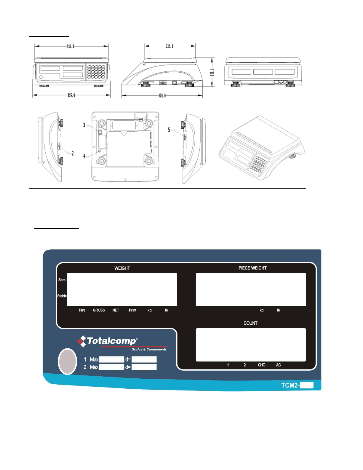
Scale dimension
WxDxH: 355x370x131 (mm) or 14”x14½”x5” (inch)
Platter size:
WxD: 335X225 (mm) or 13”x 9” (inch)
The 2nd platform
Number of platform:2;
division numbers : n=1000-30000;
division value: d=0.0001-0.0002-0.0005---0.001-0.002-0.005---
0.01-0.02-0.05---0.1-0.2-0.5---1-2-5 kg/lb
4
2. Housing
Interface: (2) load cell connector DB9 Male (3) Rocker switch
(4) AC power adapter input (5) RS232 connector DB9 Female
3. Faceplate
3.1 Front Display Panel:
5
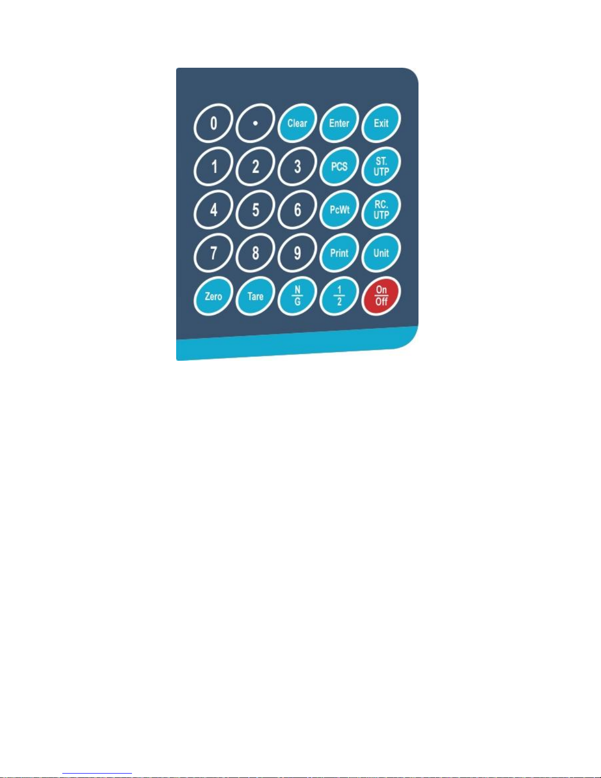
3.2 Key Pad
3.3 Symbol Meaning:
3.3.1 WEIGHT: Weight window.
3.3.2 PIECE WEIGHT:Piece weight window.
3.3.3 COUNT:Count window.
3.3.4 ZERO:Zero indicator.
3.3.5 TARE:Tare indicator.
3.3.6 Kg/Lb:Weight unit indicator.
3.3.7 Kg/Lb: Piece weight indicator.
3.3.8 PRINT:Data output indicator.
3.3.9 1/2:1: Main platform is used; 2: Remote platform is used.
3.3.10 CHG:Battery charging indicator.
3.3.11 AC:AC adaptor in-use indicator.
3.3.12 PCS: Enter number of pieces in sample
3.3.13 GROSS: Gross weight is displaying
3.3.14 Net: Net weight is displaying

6
4. Keys function Summary
4.1 0~9: numeric keys:Enter numerical data.
4.2 CLEAR: Clear the input data and accumulated pieces.
4.3 EXIT: When scale is not in normal weighing mode, EXIT key is used to exit and back to normal weighing
mode.
4.4 ENTER: Confirm the operation or save the data.
4.5 ZERO: Set the zero point when scale is stable, zero range: power-on zero point ±5%FS.
4.6 TARE: Set tare weight when scale is stable, tare range: -100% to +100%FS. Switch to NET.
4.7 UNIT: Select weight unit between Kg or Lb.
4.8 PCWT: Press down, go to directly input piece weight mode.
4.9 PCS: Press down, go to Input sample quantity and calculate piece weight mode.
4.10 ST.UTP: Set and Store a UTP:to set its piece weight, tare weight and its unit mode.
4.11 RC.UTP: Recall a UTP: recall stored piece weight, tare weight and its unit mode.
4.12 N/G: Press down to toggle between net and gross
4.13 PRINT: Output the data via RS232 port.
4.14 1/2: To select remote platform or local platform.
4.15 ON/OFF: Turn on the scale, or turn off the scale.
4.16 ON/OFF +0: Press down more than three seconds to enter the calibration mode.
4.17 ON/OFF +1: Press down more than three seconds to setup the LCD’s contrast and Backlight mode setting
4.18 ON/OFF +2: Press down more than three seconds to setup the auto-off time.
4.19 ON/OFF +3: Press down more than three seconds to enter display A/D inner code/working voltage mode
4.20 ON/OFF +4: Press down more than three seconds to enter RS232 parameters setup mode
4.21 ON/OFF +5: Press down more than three seconds to enter the date and time setup mode
4.22 ON/OFF +6: Press down more than three seconds to enter ID setup mode
4.23 ON/OFF +TARE: Press down more than three seconds to enter setup parameters of the second platform
4.24 ON/OFF +PRINT: Enter LCD test mode.
 Loading...