

Page 1

1
TCM2
Series
Counting Scale
Operation Manual
V1.0
Contents Subject to Change without Notice
Page 2

2
CONTENT
1. Specification ......................................................................................... 3
2. Housing ................................................................................................. 4
3. Faceplate .............................................................................................. 4
4. Keys function Summary ...................................................................... 6
5. Weighing Operation ................................ ............................................. 7
6. Calibration .......................................................................................... 11
7. LCD contrast and Backlight mode setting ....................................... 12
8. Auto-off time setting .......................................................................... 12
9. Display A/D inner code and working voltage ................................... 12
10. The details about RS232 communication ....................................... 13
11. Date and time setting ....................................................................... 14
12. ID setting ........................................................................................... 14
13.The second Platform Parameters setting ........................................ 15
14. LCD test mode .................................................................................. 15
15. The meaning of the special displayed character ........................... 16
16. Messages & Symbols ....................................................................... 17
17. Trouble Shooting .............................................................................. 18
18. Packing List ...................................................................................... 19
19. Version History ................................................................................. 19
Page 3

3
TCM2 Counting Scale Instruction Manual
Thank you for purchasing Model TCM2 Counting Scale. Please read all operating instructions
carefully before using and note the following points:
Avoid using in extreme heat, cold or wet and the environment which has intensive change in
temperature, humidity and pressure.
Allow sufficient warm up time after turn the scale on, to allow the internal components and load
cell to have enough time to stabilize and balance heat.
Do not operate near an in-use cell phone, radio, computer or other electronic device as these
devices emit RF and maybe cause unstable scale readings.
1. Specification
Model No
TCM2-15
TCM2-30
TCM2-60
Capacity (FS)
6kg/15lb
15kg/30lb
30kg/60lb
Division
0.2g/0.0005lb
0.5g/0.001lb
1g/0.002lb
Max weight
6.0018kg/12.0045lb
15.0045kg/30.009lb
30.009kg/60.018lb
Min Reference
Sample weight
30g
75g
150g
Min. piece weight
0.02g/0.00005lb
0.05g/0.0001lb
0.1g/0.0002lb
Tare range
3kg / 6lb
6kg / 15lb
15kg / 30lb
UTP No.
256 (include unit, tare weight, piece weight)
Zero range
Power-on zero range:calibration zero point ±15%FS_kg;
Zero Key range:power-on zero±5%FS_kg
Tare range
0-100%FS
LCD display
0.73”,18 digits:6 digit for weight,6 digit for piece weight,6 digit for pieces
RS232
Built in
Working temp.
0℃ ~ 40℃
Power supply
(1)12Vdc≥500mA with positive center AC adaptor or 6Vdc4AH lead-acid battery.
(2)Average working current is about 120mA(excluding current of charger, printer, and
backlight) (3) When using AC adaptor, the lamp of “AC” is on. When charging the
battery, the lamp of “CHG” is on.
Rechargeable
battery life
The rechargeable battery can make scale continuously work for more than 24 hours after
fully recharged and without remote platform and backlight. When the battery voltage is
below 5.6v, the “Lo.bat” will be displayed, and beep for 10 seconds and then auto off.
Scale dimension
WxDxH: 355x370x131 (mm) or 14”x14½”x5” (inch)
Platter size:
WxD: 335X225 (mm) or 13”x 9” (inch)
The 2nd platform
Number of platform:2;
division numbers : n=1000-30000;
division value: d=0.0001-0.0002-0.0005---0.001-0.002-0.005---
0.01-0.02-0.05---0.1-0.2-0.5---1-2-5 kg/lb
Page 4
4
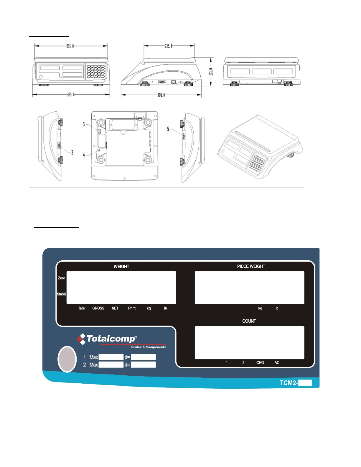
2. Housing
Interface: (2) load cell connector DB9 Male (3) Rocker switch
(4) AC power adapter input (5) RS232 connector DB9 Female
3. Faceplate
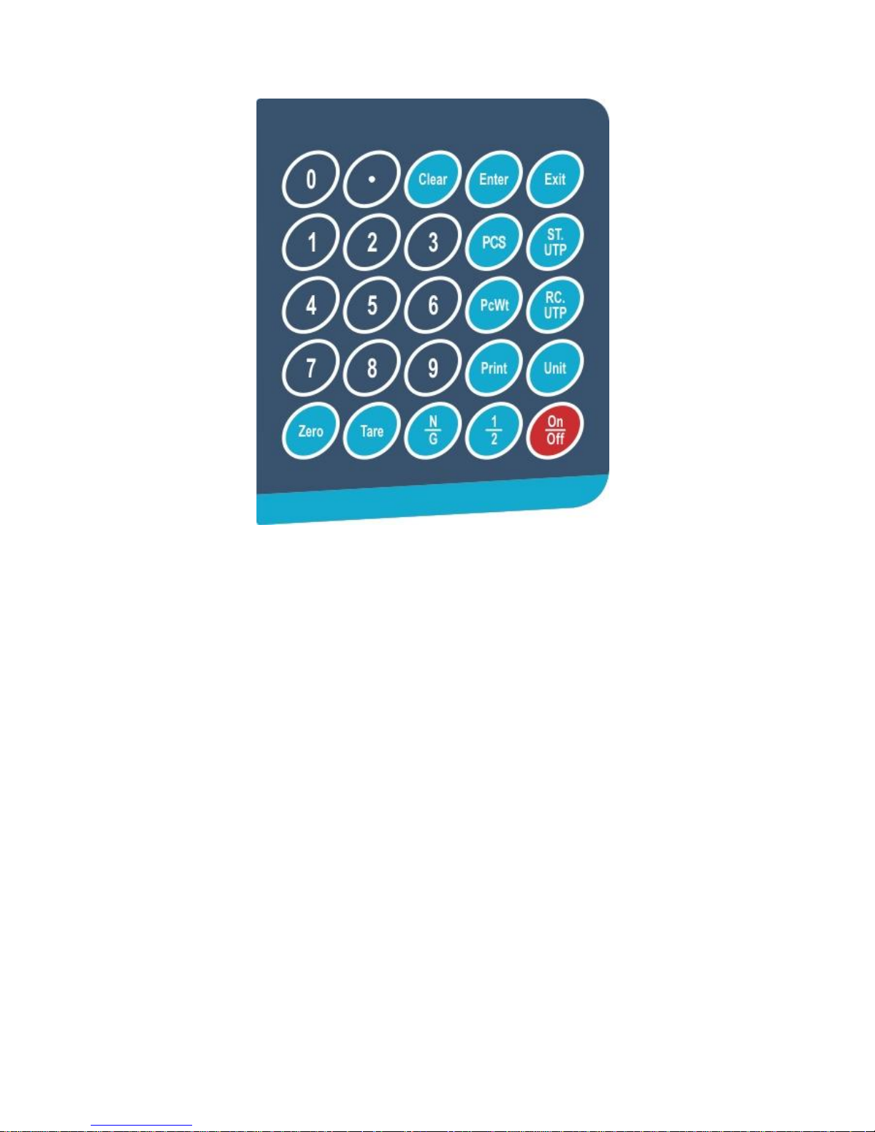
3.1 Front Display Panel:
Page 5
5
3.2 Key Pad
3.3 Symbol Meaning:
3.3.1 WEIGHT: Weight window.
3.3.2 PIECE WEIGHT:Piece weight window.
3.3.3 COUNT:Count window.
3.3.4 ZERO:Zero indicator.
3.3.5 TARE:Tare indicator.
3.3.6 Kg/Lb:Weight unit indicator.
3.3.7 Kg/Lb: Piece weight indicator.
3.3.8 PRINT:Data output indicator.
3.3.9 1/2:1: Main platform is used; 2: Remote platform is used.
3.3.10 CHG:Battery charging indicator.
3.3.11 AC:AC adaptor in-use indicator.
3.3.12 PCS: Enter number of pieces in sample
3.3.13 GROSS: Gross weight is displaying
3.3.14 Net: Net weight is displaying
Page 6

6
4. Keys function Summary
4.1 0~9: numeric keys:Enter numerical data.
4.2 CLEAR: Clear the input data and accumulated pieces.
4.3 EXIT: When scale is not in normal weighing mode, EXIT key is used to exit and back to normal weighing
mode.
4.4 ENTER: Confirm the operation or save the data.
4.5 ZERO: Set the zero point when scale is stable, zero range: power-on zero point ±5%FS.
4.6 TARE: Set tare weight when scale is stable, tare range: -100% to +100%FS. Switch to NET.
4.7 UNIT: Select weight unit between Kg or Lb.
4.8 PCWT: Press down, go to directly input piece weight mode.
4.9 PCS: Press down, go to Input sample quantity and calculate piece weight mode.
4.10 ST.UTP: Set and Store a UTP:to set its piece weight, tare weight and its unit mode.
4.11 RC.UTP: Recall a UTP: recall stored piece weight, tare weight and its unit mode.
4.12 N/G: Press down to toggle between net and gross
4.13 PRINT: Output the data via RS232 port.
4.14 1/2: To select remote platform or local platform.
4.15 ON/OFF: Turn on the scale, or turn off the scale.
4.16 ON/OFF +0: Press down more than three seconds to enter the calibration mode.
4.17 ON/OFF +1: Press down more than three seconds to setup the LCD’s contrast and Backlight mode setting
4.18 ON/OFF +2: Press down more than three seconds to setup the auto-off time.
4.19 ON/OFF +3: Press down more than three seconds to enter display A/D inner code/working voltage mode
4.20 ON/OFF +4: Press down more than three seconds to enter RS232 parameters setup mode
4.21 ON/OFF +5: Press down more than three seconds to enter the date and time setup mode
4.22 ON/OFF +6: Press down more than three seconds to enter ID setup mode
4.23 ON/OFF +TARE: Press down more than three seconds to enter setup parameters of the second platform
4.24 ON/OFF +PRINT: Enter LCD test mode.
Page 7

7
5. Weighing Operation
5.1 Turn the power on and off
5.1.1 When the scale is off, press “ON/OFF” key to power on the scale. The self-test will run and the scale will
give the zero reading. Now it is ready for weighing.
5.1.2 When the scale is beyond the zero point range after powering on (Calibration zero point±15%FS), the scale
displays “Err04”or“Err05”.
5.1.3 Under the normal weighing mode, press “ON/OFF” to power off the scale.
5.2 Operation of Zero Key
5.2.1 Under the normal weighing mode, the zero function can be operated when the scale reading is stable.
5.2.2 The scale will display “Err04”or“Err05” when the scale is over zero range.
5.3 Operation of Tare Key
5.3.1 This operation includes weight tare and keypad tare, Net weight=Gross weight-Tare weight
5.3.2 Set Weight tare:
In either gross or net weighing mode, when scale reading is stable, press “Tare” key to set the weight tare.
5.3.3 Set keypad tare:
In the normal weighing mode, input the tare weight to the weight window by numerical keys, and press
“Tare” key to confirm the setting of keypad tare weight, or press “RC.UTP” key to recall the stored keypad
tare weight. Use “Exit” key to exit this mode.
5.3.5 Example:
5.3.5.1 Weight-tare set:
Power on the scale
Put 100g on the platter
Press Tare key to set Weight-tare to 100g
Remove the weight, the scale reads -0.100kg
Put 200g on the platter
Press Tare key
Remove the weight, the scale reads -0.200kg
Tare
The scale reads 0kg
5.3.5.2 Keypad-tare set:
Power the scale on
Input 200 and confirm by” TARE” key to set keypad-tare weight to 200g
The scale reads -0.200kg
Input 100 and confirm by “TARE” key to set Digit-tare weight to 100g
The scale reads -0.100kg
5.5 Changing Weighing unit
Under the normal weighing mode, press “UNIT” key to select the unit between kg and lb.
Page 8

8
5.6 Print
5.6.1 Under the normal weighing mode, when the scale reading is stable, press “PRINT” key to output the data
via RS232 interface as following format.
5.6.2 Print Out format (ref. to 10.8, the scale is connected to a PC and the PC is a HOST device)
5.7 To count when the average piece weight is known but not stored into memory (Input the piece weight
directly)
5.7.1 Under the normal weighing mode, press “PcWt” to enter this mode. The WEIGHT window displays the
current total weight, the COUNT window displays “PCwt” (Piece Weight), the PIECE WEIGHT window
displays the input piece weight.
5.7.2 Press numerical keys 0~9 and clear key to input the piece weight.
5.7.3 Press ENTER key to save and record the input, or press EXIT key to exit this mode and return back to the
normal weighing and counting mode.
5.7.4 Note:
The piece weight must be over or equal to the required minimum piece weight. If the input piece weight is
less than the above range, the data will be not accepted and the scale will be reminded by “Lo.PCwt”
when ENTER key be pressed.
5.8 To count when the average piece weight is unknown and not stored into memory (Input the samples
quantity to calculate the piece weight)
5.8.1 Under the normal weighing mode, if the quantity of objects loaded onto the platter is known, press PCS
key to enter into this mode. The WEIGHT window displays the weight, PIECE WEIGHT window displays
“SPL.PCS” (Sample Pieces) and COUNT window displays the input quantity.
5.8.2 Press numerical keys 0~9 and clear key to input the know quantity.
5.8.3 Press ENTER key to save and record the input, or press EXIT key to exit this mode and return back to the
normal weighing and counting mode.
5.8.4 Note:
The piece weight calculated by known quantities and weight must be over or equal to the minimum piece
weight limit. If the input piece weight is less than the above range, the data will be not accepted and the
scale will be reminded by “Lo.SPwt” when ENTER key be pressed, then it back to use original piece
weight.
5.10 To store information into memory ID (Set UTPs)
Whether TARE and Average Piece Weight are known or unknown.
Start:
5.10.1 Press “ST.UTP” key to enter this mode. The WEIGHT window displays “Set.UTP” (This means the scale is
under piece weight setup and storing mode), The COUNT window displays “Addr.” (This means the unit
address of item needs to be set, the address range is 1-256), the PIECE WEIGHT window displays the
input Addr data.
5.10.2 Input address: Use numerical keys 0~9 to input the address to be used for this item. Press “ENTER” key
to confirm and go to the next step, or press EXIT key to exit this mode and return back to the normal
weighing and counting mode.
5.10.3 Select weight unit: The PIECE WEIGHT window shows “kg” or “lb”, which means the unit of the stored
piece weight is kg or lb,the COUNT window shows “Unit”
5.10.4 Use UNIT key to choose kg or lb, press ENTER key to confirm and go to the next step, or press EXIT key to
Page 9

9
exit this mode and return back to the normal weighing and counting mode.
5.10.5 Set tare weight: The PIECE WEIGHT window shows “Sample” or “Input”, which means the tare weight is
unknown (Sample) or known (Input), the COUNT window shows “tar.mod” (set getting tare weight mode).
5.10.6 Use 0~9 key to choose unknown or known tare weight, press ENTER key to confirm and go to the next step
(STEP5.10.6.1 or STEP5.10.6.2), or press EXIT key to exit this mode and return back to the normal
weighing and counting mode.
5.10.6.1 Unknown tare weight: make scale at zero point and “ZERO” is lighted, put container on platter, weight
will be shown in PIECE WEIGHT window, the COUNT window shows “tar.SPL” (Sample tare weight).
Press ENTER key after scale is stable; the tare weight will be stored into memory.
5.10.6.2 Known tare weight: the original tare weight will be shown in PIECE WEIGHT window, The COUNT
window shows “tar.Inp” (Input tare weight). if no need modifying the weight, just press ENTER key to
confirm, otherwise, use numerical keys 0~9, “.’’ and CLEAR key to input the known tare weight. Press
“Enter” key to confirm and store it into memory, or press EXIT key to exit this mode and return back to the
normal weighing and counting mode.
5.10.7 Set piece weight: The PIECE WEIGHT window shows “Sample” or “Input”, which means the piece weight
is unknown (Sample) or known (Input), the COUNT window shows “Pct.mod” (set getting piece weight
mode).
5.10.8 Use 0~9 key to choose unknown or known piece weight, press ENTER key to confirm and go to the next
step (STEP5.10.8.1 or STEP5.10.8.2), or pres EXIT key to exit this mode and return back to the normal
weighing and counting mode.
5.10.8.1 Unknown piece weight: The COUNT window shows “Pct.SPL” (means SAMPLE piece weight), PIECE
WEIGHT window shows samples net weight.
5.10.8.1.1 If need, use TARE or ZERO key to make scale read 0, Put samples on platter, weight will be shown in
PIECE WEIGHT window. Press ENTER key after scale is stable.
5.10.8.1.2 The COUNT window shows “Inp.Pcs” (means Input samples pieces), PIECE WEIGHT window shows
original pieces.
5.10.8.1.3 If no need modifying the number, just press ENTER key to confirm, otherwise, use numerical keys 0~9
and Clear key to input the known pieces, Press ENTER key to confirm and go to the next step, or press
EXIT key to exit this mode and return back to the normal weighing and counting mode.
5.10.8.2 Known piece weight: The COUNT window shows “Pct.Inp” (means input piece(s) weight), The PIECE
WEIGHT window shows original piece(s) weight.
5.10.8.2.1 If no need modifying the piece weight, just press ENTER key to confirm, otherwise, use numerical keys
0~9, ‘.' and clear key to input the known piece weight. Press “Enter” key to confirm and store it into
memory and go to the next step, or press EXIT key to exit this mode and return back to the normal
weighing and counting mode.
5.10.8.2.2 The COUNT window shows “Inp.Pcs” (means Input pieces number of the weight that you key in at
above step 5.10.8.2.1) PIECE WEIGHT window shows original pieces. If no need modifying the number,
just press ENTER key to confirm; If the weight that you key in on step5.10.8.2.1 is the weight of one
piece of material, “1” should be input here; otherwise, use numerical keys 0~9 and Clear key to input
the known pieces, Press “Enter” key to confirm and go to the next step, or press EXIT key to exit this
mode and return back to the normal weighing and counting mode.
Note: Input this number can make counting more accuracy. e.g. a counting scale (TCM2-60) which
capacity =30kg,division=1g, and min piece weight = 0.1g is used, and we know the piece weight of one
material is 0.159g, if you key in directly this piece weight, only0.1g or 0.2g can be input, this will cause big
error of counts. So, in this case, we can input159g in step5.10.8.2.1 and input 1000 in step 5.10.8.2.2,
this will increase the accuracy of counting largely
5.10.9 If the proper piece weight is good, all the data (include weight unit, tare weight, piece weight) will be
stored into memory and go to next item to set, repeat operations from step 5.10.1
Page 10
10
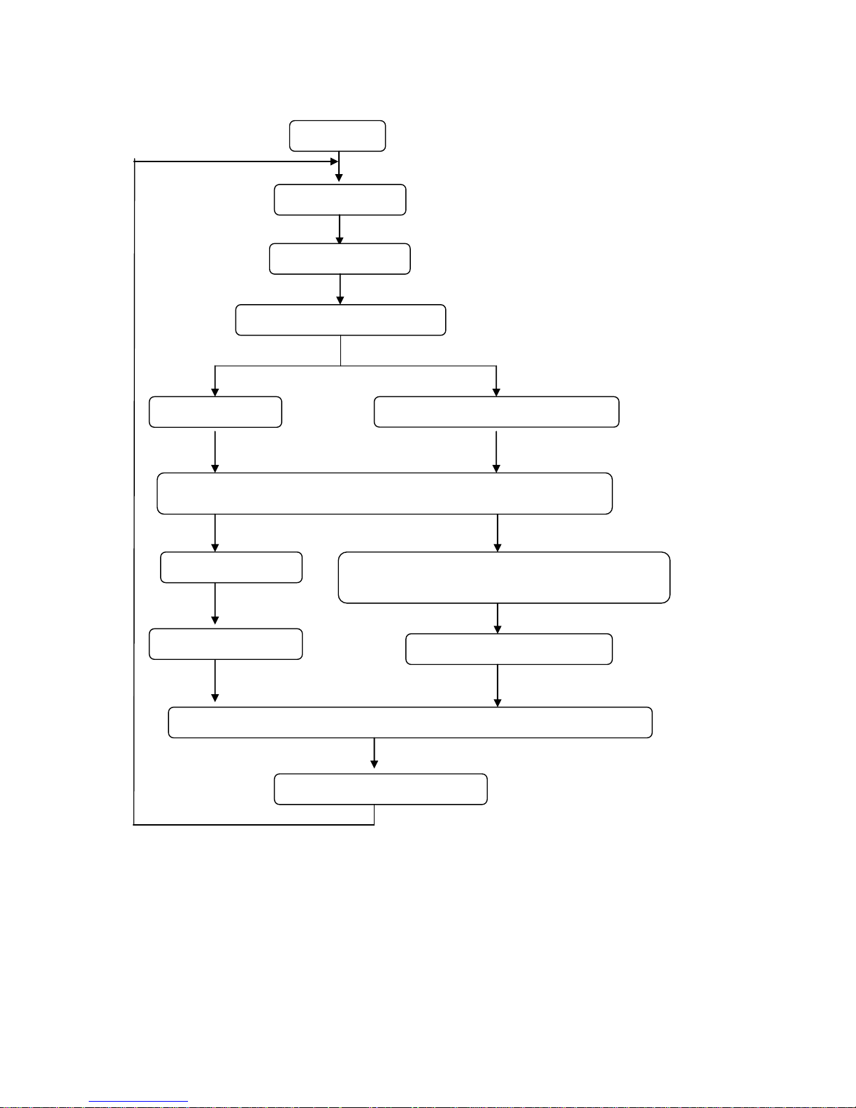
5.10.10 Summary of the flow chart:
Put container on scale to get tare weight
Prog
Input UTP address
Select weight unit
Select tare weight is known or
Input TARE weight
Select piece weight is known or unknown
Input weight
Put samples in to container to get samples net weight
Input samples quantity
Store weight unit, tare weight and piece weight
Known
Unknown
Press Enter when it’s stable
Known
Unknown
Next item (next address)
Input quantity
Page 11

11
5.11 Recall information from memory
5.11.1 Under the normal weighing mode, press “RC.UTP” to enter this mode,then “RC.UTP” will be displayed in
WEIGHT window (This means the scale is ready to recall the stored piece weight and tare weight), the
COUNT window will display “Addr.” (This means the address of item needs to be input, the Addr range is
001-256).The PIECE WEIGHT window displays the input Addr.
5.11.2 Use numerical keys 0~9 and CLEAR key to input the Addr. Press ENTER key to confirm and go to the
next step, or press EXIT key or CLEAR key to exit this mode to return back to the normal weighing and
counting mode.
5.11.3 Then the COUNT window displays will display ERR40 if stored data is not correct; otherwise, stored weight
unit, tare weight, piece weight will be used, and the scale will display the quantity.
6. Calibration
6.1 Under the normal weighing mode,press and hold 0 and ON/OFF key for more than 3 seconds to enter the
calibration mode.
6.2 After entering into the mode, the WEIGHT window displays “CAL” the PIECE WEIGHT window displays
“Unit.0” or “Unit.1”, the COUNT window displays“------”.
6.3 Use UNIT key to choose the calibration unit kg or lb (the corresponding unit indicator will be lighted), use EXIT
to exit the mode, or ENTER key to confirm the unit and go to the next step.
6.4 The PIECE WEIGHT window displays “unloAd” (this means that the scale is ready to calibrate the zero point,
please remove any weight from the platform), the COUNT window displays the output inner code of A/D. When
the scale is stable and the unit indicator stops flashing, press ENTER key to confirm the zero point calibration,
or use EXIT key to exit the mode.
6.5 The display of the WEIGHT window remains the same, the PIECE WEIGHT window displays “LoAd1” (this
means it will be calibrated on standard weight for first point). Place a standard weight (more than 10%FS
weight) on the center of the scale platter, when the scale is stable and the unit indicator stops flashing, press
ENTER to confirm, or use EXIT key to exit the calibration mode.
6.6 The display of the WEIGHT window remains the same, the PIECE WEIGHT window displays “InP.Ld”(Input
Load Weight),the COUNT window displays 0,use 0-9 numerical key or Clear key to input loaded standard
weight, then press ENTER key for confirmation. If this point can’t be calibrated correctly (maybe the weight
load onto scale is too small, maybe the input data is incorrect…), it will display “CAL.Er” and return back to
step 6.4 for re-calibration.
6.7 The display of the WEIGHT window remains the same, the PIECE WEIGHT window displays “LoAd2” (this
means It will be calibrated on standard weight for second point). To skip the second point calibration, press
ENTER key to go to step 6.11. To continue second point calibration, place a standard weight (more than
10%FS weight, and larger than the weight used on LoAd1) on the center of the scale platter, press ENTER to
confirm. if the standard weight is <= LoAd1, it will go to step6.11.
6.8 The display of the WEIGHT window remains the same, the PIECE WEIGHT window displays “InP.Ld”(Input
Load Weight),the COUNT window displays 0,use 0-9 numerical key or Clear key to input loaded standard
weight, then press ENTER key for confirmation. If this point can’t be calibrated correctly (maybe the weight
load onto scale is too small, maybe the input data is incorrect…), it will display “CAL.Er” and return back to
step6.4 for re-calibration.
6.9 The display of the WEIGHT window remains the same, the PIECE WEIGHT window displays “LoAd3” (this
means it will be calibrated on standard weight for third point). To skip the third point calibration, press ENTER
Page 12

12
key to go to step 6.11. To continue third point calibration, place a standard weight (more than 10%FS weight,
and larger than the weight used on LoAd2) on the center of the scale platter, press ENTER to confirm the
standard weight calibration after the scale is stable and the unit indicator stops flashing, if the weight is <=
LoAd2 , it will go to step 6.11
6.10 The display of the WEIGHT window remains the same, the PIECE WEIGHT window displays “InP.Ld”(Input
Load Weight),the COUNT window displays 0,use 0-9 numerical key or Clear key to input loaded standard
weight, then press ENTER key for confirmation. If this point can’t be calibrated correctly (maybe the weight
load onto scale is too small, maybe the input data is incorrect…), it will display “CAL.Er” and return back to
step 6.4 for re-calibration.
6.11 When the PIECE WEIGHT window displays “unLoAd” again,the scale is ready to re-confirm the zero point,
move away any weight on the scale, after the scale is ready and unit indicator stops flashing, press ENTER to
confirm.
6.12 After the calibration completes, the scale will re-initialize to be ready for normal weighing.
6.13 If an error occurred in calibration, the scale will display CAL.Err (this normally means incorrect data input or
loading weight), please return back to the last step or use EXIT to exit the calibration mode.
7. LCD contrast and Backlight mode setting
5.1 Under the normal weighing mode, press and hold down ON/OFF and 1 key at the same time until the WEIGHT
window shows “Setup”, PIECE WEIGHT window shows “LCd.CST” (LCD contrast) and the COUNT window
shows the contrast level x(x=1-9,default is 5). Use the numerical keys to input the contrast level, and press
ENTER key for confirmation. Press EXIT key to exit this mode and the scale will automatically reset.
5.2 When WEIGHT window shows “BLGT.MD” (backlight mode) and the COUNT window shows the backlight
mode code x(x=0-2), Use the numerical keys to input the backlight mode, and press ENTER key for
confirmation. Press EXIT key to exit this mode and the scale will automatically reset.
x=0 – back light is always off
=1 – back light is always on
=2 – back light is automatically turns on or off
8. Auto-off time setting
Under the normal weighing mode, press and hold ON/OFF and 2 key at the same time until the scale displays
“SetuP” in WEIGHT window, “A.OFF.t” in PIECE WEIGHT window and auto-off time xx(xx=00~30) in
COUNT window. Use numerical keys to input the auto-off time and press “ENTER” key for confirmation. Press
EXIT key to exit this mode and the scale will automatically reset.
9. Display A/D inner code and working voltage
9.1 When in normal working mode, press ON/OFF and 3 key at the same time till the PIECE WEIGHT window
shows “codE” to enter this mode. Now WEIGHT window will show “UoL.x.x” (Voltage x.x V), this means the
inner working voltage is x.x V. If the scale uses AC power adaptor, the voltage is the power adaptor voltage
after regulating. If the scale is not powered by adaptor, the displayed voltage is the battery voltage. It will
display A/D internal code in COUNT window.
9.2 Use 1/2 key to view the codes from the remote platform or local platform.
9.3 Use TARE key to view “gross” or “net” codes.
9.4 Press EXIT key to exit this mode, and the scale will automatically reset.
Page 13

13
10. The details about RS232 communication
10.1 Under the normal working mode, press and hold ON/OFF and 4 key at the same time until the WEIGHT
window shows “SetuP”. Under this mode, you can set the RS232 baud rate, data format and communication
format.
10.2 When PIECE WEIGHT window shows “232.OUT”, use 0 or 1 key to enable (=1) or disable (=0) RS232 output.
Use Enter key to confirmation to go to the next step, or EXIT key to exit this mode.
10.3 When the PIECE WEIGHT window shows “232.bPS” (bit per second) and the COUNT window shows baud
rate xxxxx, Use numerical keys 1、2、3、4、5 to choose baud rate:
1--1200bps
2--2400bps
3--4800bps
4--9600bps
5--19200bps
And use Enter key to confirmation to go to the next step, or EXIT key to exit this mode.
10.4 When the PIECE WEIGHT window shows “232.dFt” (data format), the COUNT window will display data
format xxx, Use 1、2、3 key to select data format:
1—8N0 8 bits data, no odd or even , 1 start bit, 1stop bit
2—7O1 7 bits data, 1 even check, 1 start bit, 1stop bit
3—7E1 7 bits data, 1 odd check, 1 start bit, 1stop bit,
And use Enter key to confirm the input and go to the next step, or use EXIT key to exit this mode.
10.5 When the PIECE WEIGHT window shows “Urt.cFt” (communication format), the COUNT window shows
communication format xxx. Use the numerical keys 0, 1, 2, 3 to select the communication format:
0---Non-communication
1---When scale becomes stable, it will output the data automatically once, the format is as follows.
2---When scale is stable, the data will be output after pressing PRINT key, the format is as follows.
3---When scale becomes stable or PRINT key is pressed, the data will be output once. The format is as
follows:
<LF>ID: xxxxxx<CR><EXT> ; scale’s ID
<LF>Date: YY/MM/DD<CR><EXT> ; Date
<LF>Time: hh:mm<CR><EXT> ; Time
<LF>Gross: xxx.xxx kg (or lb) <CR> <EXT> ; Gross weight
<LF>Tare: xxx.xxx kg (or lb) <CR> <EXT> ; Tare weight
<LF>Net: xxx.xxx kg (or lb) <CR> <EXT> ; Net weight
<LF>Pc.wt.: xxxxxx.xx kg(or lb)<CR><EXT> ; Piece weight
<LF>Count: xxxxxxxx pcs<CR> <EXT> ; Counts
Note:The ID、Date and Time information can only be printed out after setting.
<LF> Line Feed character (hex 0AH)
<CR> Carriage Return character (hex 0DH)
<EXT> End of Text character (hex 03)
Page 14

14
10.6 RS-232 connects between scale and host:
Scale --------------------------------Cable(9 pins)------------------------Host (Computer)
DB9 (Female) ----------- DB9 (Male Connector) ------------------------ Host connector
PIN2 TXD----------------------2---------------------2----------------------------PIN2 RXD
PIN3 RXD----------------------3--------------------3-----------------------------PIN3 TXD
PIN5 GND---------------------5---------------------5-----------------------------PIN5 GND
PIN4 DSR---------------------4---------------------4-----------------------------PIN4 DTR
PIN6 DTR---------------------6---------------------6-----------------------------PIN6 DSR
PIN7 CTS---------------------7---------------------7-----------------------------PIN7 RTS
PIN8 RTS---------------------8---------------------8-----------------------------PIN8 CTS
PIN1 NC----------------------1---------------------1------------------------------PIN1 NC
PIN9 NC----------------------9---------------------9------------------------------PIN9
Note: The PIN4, PIN6, PIN7 and PIN8 are shorted in scale!
Scale ---------------------------Printer
DB9 connector --------------- (printer supplied connector XX)
PIN2 TXD -------------------- Printer RXD
PIN3 RXD -------------------- Printer TXD
PIN5 GND -------------------- Printer GND
11. Date and time setting
11.1 Under the normal working mode, press and hold 5 and ON/OFF key for more than 3s to enter into this mode.
In this mode, you can set the system date and time. (Note: the date and time in scale will be lost after the
scale power off if no Real Time Clock module is installed)
11.2 After entering into this mode, the WEIGHT window will display “SEtuP”, the PIECE WEIGHT window will
display “dAtE”(date) and the COUNT window will display the current date xx.xx.xx (format:YY.MM.DD).
11.3 Use the numerical keys to input the date(format:YY.MM.DD), use Enter key to confirm and go to the time
setting mode.
11.4 Then the weight window displays “SetuP”,the PIECE WEIGHT displays “timE” (time) and the total price
window displays the current time xx.xx.xx.
11.5 Use the numerical keys to input the time(Format:hh.mm.ss), press Enter to confirm the input and exit this
mode.
12. ID setting
12.1 Under the normal working mode, press and hold 6 and ON/OFF key for more than 3s to enter this mode. In
this mode, you can set ID code.
12.2 After entering this mode, the WEIGHT window displays “SEtuP”, the PIECE WEIGHT window displays “Id”
and the COUNT window displays Id code(the default Id code is 000000) xxxxxx.
12.3 Use the numerical keys to input ID code,then press ENTER key to confirm the input and exit this mode.
Page 15

15
13.The second Platform Parameters setting
13.1 Under the normal working mode, press and hold TARE and ON/OFF key for more than 3s to enter this mode.
In this mode, you can set parameters about the second platform.
13.2 The weight window displays “SETUP”, the PIECE WEIGHT window display “M.UNIT” (Main weight Unit) and
the COUNT window display “kg/lb”.
13.3 Use UNIT key to select main unit, use ENTER key to confirm or EXIT to exit this mode.
13.4 The PIECE WEIGHT window displays “Main.n” (main division number under main weight unit), the COUNT
window display the number of division.
13.5 Use numerical keys and CLEAR key to input the value of the division number (n=3000-30000), use ENTER
key to confirm or EXIT to exit this mode.
13.6 The PIECE WEIGHT window displays “Main.d” (main division value under main weight unit), the COUNT
window display the value of division.
13.7 Use numerical keys 0-1 key to input the value of the division (d=0.0001-5), use ENTER key to confirm or EXIT
to exit this mode
13.8 The PIECE WEIGHT window displays “2nd.n” (the division number under the 2nd weight unit), the COUNT
window display the number of division (the division number under second unit, the max is 1.25*Main.n).
13.9 Use numerical keys and CLEAR key to input the value of the division number, use ENTER key to confirm or
EXIT to exit this mode
13.10. Pin connection for second scale
Scale DB9 Male connector:
PIN 1: Excitation +
PIN 2: Signal +
PIN 3: Signal -
PIN 4: Excitation -
14. LCD test mode
14.1 Long press the ON/OFF+PRINT key, until all segments of LCD are displayed
14.2 (a) Press 0 key--- all segments are shown;
(b) Press 1 key --- different segments will be shown;
(c) Press 2 key --- segments on different COMs will be shown;
(d) Press ENTER key ---segments will be shown in turn of above a-b-c steps
14.3 Press EXIT key --- exit this mode
Page 16
16
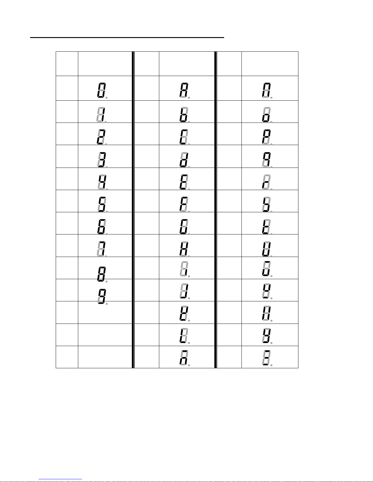
15. The meaning of the special displayed character
ASCII
LCD/LED Show
ASCII
LCD/LED Show
ASCII
LCD/LED Show
0 A N
1 B O
2 C P
3 D Q
4 E R
5 F S
6 G T
7 H U
8 I V
9 J W
K X
L Y
M Z
Page 17

17
16. Messages & Symbols
16.1 Err01 Weight signal is too large
16.2 Err02 No proper data can be displayed
16.3 Err03 Weight signal is too small
16.4 Err04 Zero point is over the setting range
16.5 Err05 Zero point is below the setting range
16.6 Err10 EEPROM can’t be accessed
16.7 Err11 Parameters in EEPROM are not same with backup data
16.8 Err12 The setting parameters in EEPROM is not in normal range
16.9 Err20 There is an error in calibration
16.10 Err30 Input signal is over ADC’s max. range
16.11 Err31 Input signal is below ADC’s min. range
16.12 Err40 Recall memory data error (data have not been set before recall it)
16.13 CAP. Data about capacity
16.14 UoL. Data about voltage
16.15 Add Data about accumulation
16.16 PCwt Data about piece weight
16.17 St.PCwt Set and store piece weight
16.18 Addr. Memory unit address
16.19 Unit: Weighing unit
16.20 Rc.PCwt Recall the stored piece weight, tare and its unit
16.21 Lo.PCwt Below the Mini Piece Weight limit
16.22 SPL.PCS Data about sample pieces
16.23 Hi.PCS Data about upper limit pieces
16.24 Lo.PCS Data about lower limit pieces
16.25 Lo.SPwt Below Mini sample weight limit
16.26 UnLoAd Unload the loaded weight
16.27 LoAd Load the weights
16.28 InP.Ld Input the load weight
16.29 CAL.oN Calibration enable switch is ON
16.30 CAL.oFF Calibration enable switch is OFF
Page 18
18
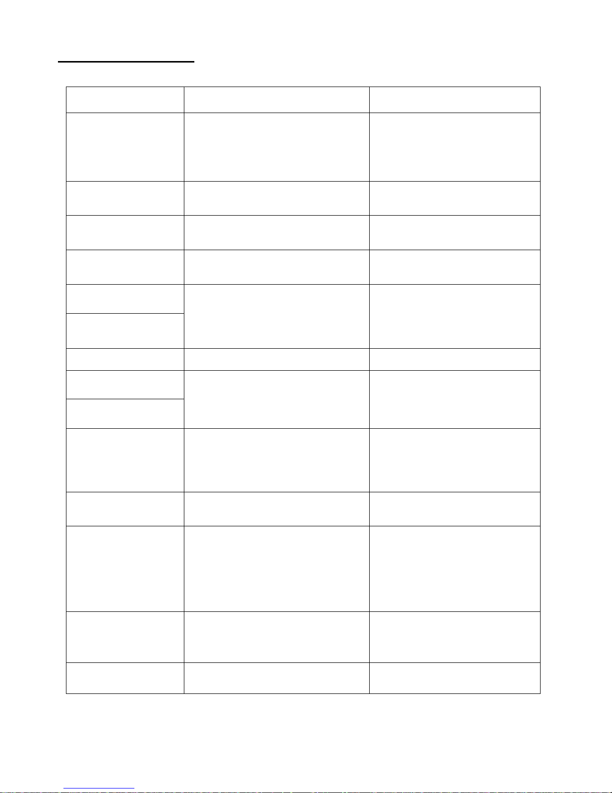
17. Trouble Shooting
SYMPTOM
PROBABLE CAUSE
REMEDY
Err01
Weight reading exceeds Overload limit,
or The weight value cannot be displayed
in the current unit of measure
Reduce load on scale until weight
value can be displayed. Use a more
appropriate unit of measure. Re-set
some parameters about units
Err03
Weight reading below Under load limit.
Install platform on scale.
Perform zero calibration
Err04
Weight exceeds Power On Zero limit
(+10%), or over ZERO key range (+5%)
Make sure scale platform is empty.
Perform zero calibration.
Err05
Weight below Power On Zero limit
(-10%) or below ZERO key range (-5%).
Install platform on scale. Perform
zero calibration.
Err30
Load cell wires to indicator are
incorrectly connected, or shorted, or
opened; or ADC, load cell are damaged
Make sure wires are ok and correctly
connected. Replace load cell or ADC
chip, Service required.
Err31
Err10
EEPROM is damaged
Replace EEPROM IC
Err11
parameters are not set or not correctly
set, or setting lost
Re-set parameters, do calibration
Err12
Err20
Calibration error, maybe input data or
loaded weight is too small, too big,
unstable, un-linear
Input correct data, load correct
weight onto platform, Service
required
Err40
UTP memory is not set, or not correctly
set, or set data lost
Re-setting these UTPs
Not turn on.
Power cord not plugged in or properly
connected. Power outlet not supplying
electricity. Battery discharged. Other
failure.
Check power cord connections.
Make sure power cord is plugged
into the power outlet. Check power
source. Replace batteries. Service
required.
Cannot zero the
display or will not zero
when turned on.
Load on scale exceeds allowable limits.
Load on scale is not stable.
Load cell damage.
Remove load on scale.
Wait for load to become stable.
Service required.
Lo.bAt is shown
Batteries are discharged.
Charge batteries
Page 19
19
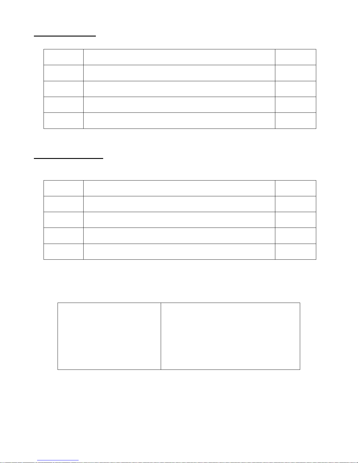
18. Packing List
No.
CONTENT
QTY
1
Scale
1
2
User manual
1
3
6V4AH lead-acid battery (included)
1
4
Real Time Clock Battery (CR2032) included
1
19. Version History
VERSION
DESCRIPTION
DATE
V1.0
Initial version
2013-05-20
Totalcomp Inc.
99 Reagent Lane
Fair Lawn, NJ 07410
Phone: (201)-797-2718
Fax: (201)-797-2287
Toll Free Phone: (800)-631-0347
Toll Free Fax: (888)-797-2288
Website: www.totalcomp.com
 Loading...