

Total Automotive Lifting Solutions Inc. TLS210SR*1, TLS210SX*1 Installation, Operation & Service Parts Manual
1
Part Number : D - TP - 10 - S
Symmetric
Total Automotive Lifting Solutions Inc.
Model Number:
TLS210SRx1
TLS210SXx1
10,000 lb. ( 4536 kg )
READ the Manual Thoroughly Before Installing,
Operating, Servicing, or Maintaining the Lift
SAVE this MANUAL and ALL INSTRUCTIONS
2300 Speers Rd. Oakville, Ontario L6L 2X8
Phone: (905) 847-1198 Fax: (905) 891-1214
www.TLSLifts.com
Two Post
Issue 00 5 E ective : May 1 , 200 9
Supersedes Issue 00 4 - April 1 5 , 200 9

2
Your new lift will provide years of dependable service if installed, operated and maintained
properly. Read and be prepared to follow all safety, installation,
operation, and maintenance instructions in this manual before
installing and operating the lift. In addition, read and follow all safety
and other information included on and with the lift be fore operating
the lift. Keep this manual in a secure place for future reference,
training and service part identification.
TABLE of CONTENTS
1. Unloading Procedure and Lift Package Contents page 3
2. Warranty and Safety page 4 - 6
3. General Requirements and Lift Specifications page 7
4. Tools Required and Pre Installation Procedures page 8
5. Installation Procedures page 9 - 10
6. Operating Instructions and Lift Maintenance page 11 - 13
7. Troubleshooting page 14
8. Lift Installation Diagrams and Parts Lists page 15 - 26
IMPORTANT : It is the shop owner's responsibility to provide a satisfactory installation
area for the lift. Lifts should only be installed indoors on level concrete floors with a
minimum of 4 inches (102mm) and 3000 psi (20.7MPa) concrete that has been aged a
minimum of 30 days. Please consult a qualified individual if any doubt exists concerning
proper installation and subsequent safe operation of the lift. Do not install the lift on asphalt
or outdoors.
Prior to installation, it is the shop owner's responsibility to provide constant electrical power
in the correct voltage, phase, etc., and all wiring for electrical hook-up of the lift. The shop
owner must insure that the electrical installation conforms to local building and safety codes.
Where required, the shop owner will provide an electrical isolation switch located in close
proximity to the lift. This switch will have an emergency stop capability and isolate electrical
power from the lift for servicing requirements.
Hydraulic oil cannot be shipped with the lift and will be supplied by either the shop owner or
the installer. ISO 32 hydraulic oil (10W non detergent hydraulic oil) must be used to fill the
reservoir tank before operating the lift.
It is the shop owner's responsibility to train all operators in
lift operation and safety.

3
UNLOADING PROCEDURE and LIFT PACKAGE CONTENTS
For your information:
All lift components are grouped together in one package held at each end by steel frames.
Unpacking Procedure:
When the lift arrives on site: - If possible have lift unloaded in the installation area.
- Check for freight damage and report immediately to the
trucking company who delivered the lift.
- Check for missing parts and report immediately to the factory.
1 - 877 - 799 - LIFT (5438) or (905) 847 - 1198
Main Components include:
Power Side Column and Carriage Assembly – 1 pc (c/w equalizing cable and 2 arm restraint assembles)
Opposite Side Column and Carriage Assembly – 1 pc (c/w equalizing cable and 2 arm restraint assembles)
Column Extensions – 2 pc
Overhead Crossmember – 3 pc (c/w 4 steel cable pulleys)
Overhead Safety Shutoff Bar – 1 pc
Arms – 4 pc (c/w arm restraint gear assemblies)
Powerpack Assembly – 1 pc
Accessory and Hardware Box includes:
Micro-switch for Overhead Safety Shutoff Bar - 1pc (c/w 2 mounting brackets and hardware)
Baseplate Shims (6mm - 3mm - 1mm assortment) - Anchor Bolt Assemblies - 10 pc
Arm Pins – 4 pc (c/w roll pins to secure them)
Rubber Stack Pad Assembly – 4 pc
Stack Pad Adapter (1½ " ) – 4 pc
Stack Pad Adapter (3”) – 4 pc
Stack Pad Adapter (6”) – 4 pc
Honda Adapter – 2 pc
Rubber Door Guards – 2 pc
Hydraulic Hose – 2 long and 1 short (also 1 hydraulic "T" fitting and powerpack adapter fitting)
Rubber Mounts for Powerpack - 4 pc
Safety Lock Release Cable – 1 pc (c/w 2 pulley brackets and fittings)
Safety Lock Cover – 2 pc
Fittings Box (bolts, washers, nuts, screws, cable ties, etc.)
ALI - WL101 Series Label Kit
ALI - " Lifting It Right " Manual
ALI - " Vehicle Manufacturer's Lifting Point Guide" (CD)
Automotive Lift Safety Tips Hang Card
Automotive Lift, Operation, Inspection and Maintenance Manual
Owner’s Manual

4
WARRANTY and SAFETY
Warranty: The multi-metric model two post lifts listed in this manual have the following
warranty from date of purchase:
Structural Components - 1 year Accessory Items - 90 days
Hydraulic and Other Components - 1 year Labor - 1 year
The above items are warranted to be free of defects in material and workmanship to the
original owner of the lift as follows: During the first year (90 days for accessories), those parts
proven after inspection to be defective shall be repaired or replaced at the option of the
manufacturer. This warranty does not extend to defects caused by ordinary wear, misuse,
abuse, improper maintenance, shipping damage or where repairs have been attempted or
made by anyone other than the manufacturer or a manufacturer certified technician. This
warranty is exclusive and in lieu of all other warranties express or implied. In no event shall
the manufacturer be liable for special, incidental or consequential damages for any breach or
delay in performance of the warranty. The manufacturer reserves the right to change
specifications, designs or add improvements to its product line without incurring any
obligation to make such changes to products sold previously.
IMPORTANT SAFETY INSTRUCTIONS
When using your garage equipment, basic safety precautions should always be followed,
including the following:
1. Read all instructions
2. Care must be taken as burns can result from touching hot parts
3. Do not operate equipment with a damaged cord or if equipment has been dropped or
damaged – until it has been examined by a qualified service person
4. Do not let a cord hang over the edge of the table, bench, or counter or come in
contact with hot manifolds or moving fan blades
5. Let equipment cool completely before putting away. Loop cord loosely around
equipment when storing
6. To reduce risk of fire, do not operate equipment in the vicinity of open containers of
flammable liquids (gasoline)
7. Adequate ventilation should be provided when working on operating internal
combustion engines
8. Keep hair, loose clothing, fingers, and all parts of body away from moving parts
9. To reduce the risk of electric shock, do not use on wet surfaces or expose to rain
10. Use only as directed in this manual. Use only manufacturer’s recommended
attachments
11. ALWAYS WEAR SAFETY GLASSES. Everyday eyeglasses only have impact resistant
lenses, they are not safety glasses
SAVE THESE INSTRUCTIONS
safety cont’d on page 5

5
Safety Continued
Basic common sense safety precautions should always be followed when installing, operating
and maintaining the lift as a risk of fire, electric shock, or injury may be present.
In addition:
1. Read and follow all safety instructions and decals included with the lift. Read and follow
all safety instructions in this manual. Read and follow the ALI "Lifting It Right" manual included with the lift. Always use the "Vehicle Lifting Points" reference guide when lifting a
vehicle – CD is included with the lift. Insure all materials stay up to date »» www.autolift.org/
2. Only trained and authorized personnel should position a vehicle and operate the lift. Do
not allow customers or bystanders to operate the lift or be in the lift area.
3. Inspect the lift daily. Do not operate if potential problems have been identified or lift
malfunctions. Do not operate if lift has damaged or broken components. Never walk or
work under the lift unless all safety locks are completely engaged.
4. Never overload the lift. The rated capacity decal is located on the powerpack column. The
hydraulic system on this lift is not designed to be a load holding devise. Mechanical safety
locks must be engaged before proceeding under the lift, with vehicle servicing, or system
maintenance. Never override operating controls. This is unsafe and will void the warranty.
5. Before driving a vehicle between the columns, position all arms to insure unobstructed
entry. Do not hit or run over arms as this could damage the lift and/or vehicle.
6. Use all 4 arms to raise a vehicle. Position all lift pads to contact vehicle manufacturer's
recommended lifting points (see "Vehicle Lifting Points" reference guide CD included with the lift). Raise lift
slowly until all pads contact the vehicle. Check all pads for complete and secure contact
with the vehicle. Check all arm restraints to insure they are engaged properly. Check
that vehicle is stable on the lift. Only after confirming these procedures, raise the lift to
desired working height.
7. Special care must be used when lifting pick-up trucks. Optional truck adapters may be
required to reach manufacturer recommended lifting points. Always use these lifting
points. Running boards and other installed accessories may also require optional adapters
Insure contents of the cargo box will not affect vehicle balance while on the lift.
8. Important: Removal or installation of heavier parts can change the vehicle's center of
gravity on the lift resulting in a critical load shift. The vehicle may then be unstable. Plan
ahead for this possibility to insure continued safety and refer to the vehicle manufacturer’s
service manual for recommended procedures.
9. Always keep the lift area free of obstructions and debris. Clean up grease and oil spills
immediately.
10. Never raise a vehicle with passengers inside. Before lowering a vehicle, check the lift and
lift area and remove all obstructions. Before removing vehicle from the lift or lift area,
position arms to the drive through position and confirm an unobstructed exit.
safety cont’d on page 6
6
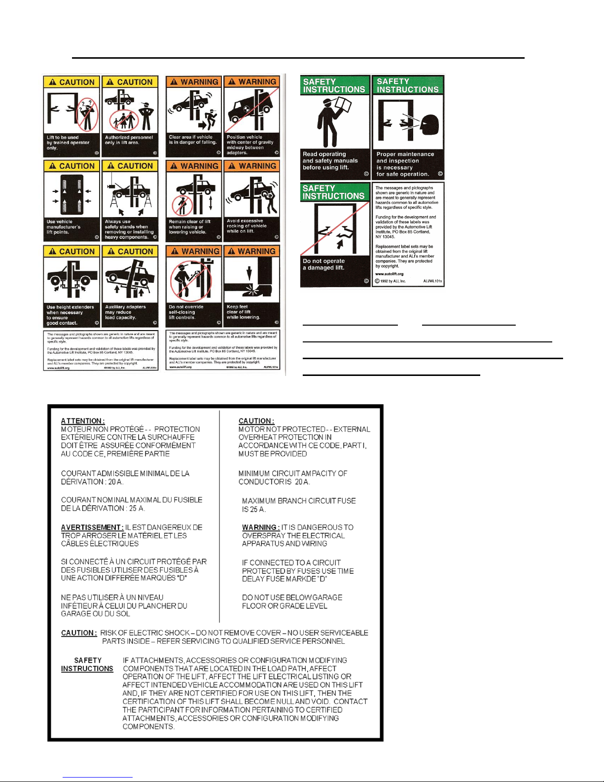
Safety Instruction and Information Decal Kit (included with the lift)
LIFT SAFETY
and LIFT
MAINTENANCE
MUST BE PART
OF YOUR
DAILY
ROUTINE
IMPORTANT : Insure Safety
Instruction decals are affixed to the
lift immediately following installation
and before the lift is used
ELECTRICAL SAFETY DECAL
Review all safety
information daily
with all lift
operators
7
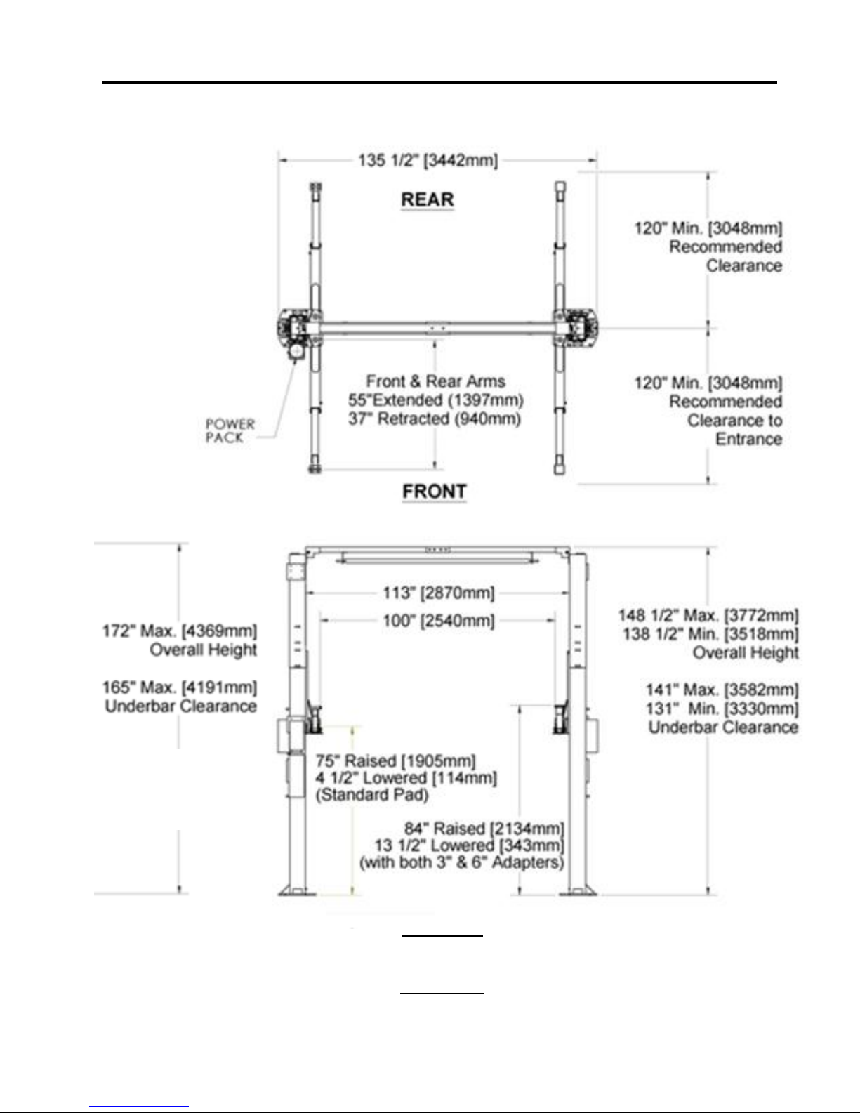
SYMMETRIC GENERAL REQUIREMENTS and LIFT SPECIFICATIONS
Ongoing quality improvements and design modifications may change specifications listed in this manual without notice
10,000 lb. Capacity (2,500 lbs. per lift pad)
Concrete:
minimum 4 inches (102mm) - 3000 psi (20.7MPa) - aged a minimum of 30 days.
Electrical:
230V - 1 ph - 60 Hz - 20 amp (standard) 230V - 3 ph - 60 Hz - 15 amp (optional)
Extended
Height
Model

8
TOOLS REQUIRED and PRE INSTALLATION PROCEDURES
Tools Required: Gather all the tools listed below.
4” x 4” Wooden Blocks (for unpacking)
16ft. Measuring Tape
Chalk Line and Chalk
Side Cutters
Crow Bar
Metric Wrenches and Ratchet Set
SAE Wrenches and Ratchet Set
Metric and SAE Allen Key Sets
Hammer
Screwdrivers
12 ft. Step Ladders - 2
(2 people using 12 ft. ladders should install the overhead crossmember assembly)
4 ft. Levels - 2
Rotary Hammer Drill with 3/4” diameter Masonry Drill Bit
Pre Installation Procedures
Before proceeding with installation, read the installation manual and insure all instructions
are fully understood and all component parts are accounted for.
1. In the installation area, identify the center line of the bay and mark the floor. Also mark
the center of bay entrance door. Connect these two points with a short chalk line in the
area where lift will be located. Draw a second chalk line at 90° to locate the positions of
both lift columns (refer to lift dimensions and bay layout on page 6). Insure each lift column is
equal distance from bay centerline and each baseplate maintains a minimum distance of
6 inches from any floor seam. Do not install if floor has cracks or deterioration that could
affect lift stability. The shop owner is responsible for confirming there are no obstructions
in the installation area like floor drains, under floor piping or electrical conduit that could
be damaged or prevent safe lift installation and secure lift anchoring. Check ceiling for
beams or heating ducts and walls for protruding structures, etc.. Model TLS210SRR 1/3
has two possible overall heights - 148½ inches or 138½ inches. Model TLS210SXR 1/3
has an overall height of 172”. Confirm that the overall height you intend to install will fit
in the bay. Insure that the lift can be safely installed in the position you have marked out on
the bay floor.
2. Place the lift on wooden blocks so that the steel shipping frames can be removed.
3. Remove protective wrapping. Clear installation area of all packaging materials.
4. Unbolt steel shipping frames and remove from installation area.
5. Carefully remove top column and lay on the floor (carriage side up).
6. Carefully remove column extensions (2 pc), cross-member (3 pc), overhead safety bar,
arms (4 pc), powerpack and hardware box from the lower column.
7. Identify powerpack column (reference diagram #1). Move (carriage side up) to
appropriate location placing the baseplate end on your floor marks. Similarly, move the
second column to the opposite location.
 Loading...