


ASSEMBLY/USER MANUAL
500 Series
Suite 5, Fairfield, 1048 Govan Road, Glasgow G51 4XS, United Kingdom.
info@totalaudiocontrol.com www.totalaudiocontrol.com

2
FEW WORDS ON ASSEMBLY
Thank you for purchasing COMPRESSOR ONE in kit form. You will have a lot of fun in building and using it.
Before rushing into building your COMPRESSOR ONE you should study this manual from front to back, and familiarise yourself with
the design before starting to solder the first component. As the expression says “one picture tells a thousand words”.
The components are packed and numbered in the correct order. The numbers correspond to the bill of materials. Open them one at
a time. Do not open the next package before completing the assembly of the previous one. There is a reason behind each stage.
Populating a PCB always starts with the smallest components. Resistors and/or small signal diodes being the first. If you solder the
larger components first you’ll have a hard time in soldering the resistors or the small signal diodes.
Before soldering a component visually check its value and designation. Although normally it is not required testing them would also
be a good practice (excluding integrated circuits) before they go on the board. We are extremely lucky to be living at a time when a
reasonably well performing digital multimeter with semiconductor testing capability or a capacitance meter can be picked up from ebay for the cost of literally a burger meal. Therefore, investing into a few handheld meters would pay dividends in the long run.
A good quality soldering iron with a fine tip and a set of hand tools are a must. Plumber’s torch does not have a place in electronics
assembly, and component leads are not trimmed using a Black Smith’s pliers. A miniature close cutting side cutter will have to be a
part of your tool kit. Equally fixing an M2 screw will not be possible with a screw driver normally used for M10 bolt. A simple spring
action desoldering pump will do fine for single sided boards. But for double sided/plated through boards, such as this, a proper
(electric motor pump action) de-soldering tool will be essential. However, you do not have to get the ones that require remortgaging your house. There are affordable ones that will also do a good job.
Most faults will arise due to incorrect components being inserted or solder bridges. It is particularly important to closely examine
the soldering of components with close pads such as transistors. Therefore, unless you have eagle eyes, checking each solder node
with a hand held or table mount magnifier as you go along will be an extremely good practice.

3
Do not stay on the components with the soldering iron for too long as there can be a possibility of causing damage. You should be
able to get in and out of a solder node within few seconds.
Safety first, be extremely careful when trimming component leads as these can easily fly off into your face. Always hold the lead with
one hand while trimming it with the other.
In general do not rush. Work methodically and have fun.
Total Audio Control
August 2019
4
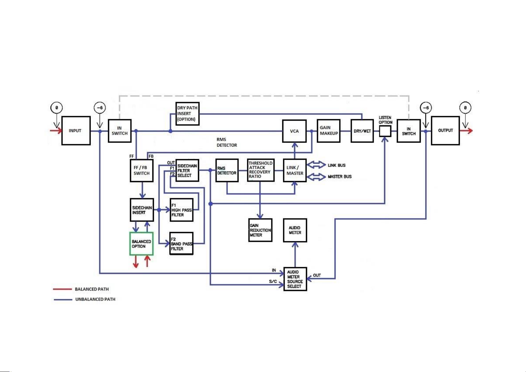
BLOCK DIAGRAM

5
SPECIFICATIONS: Measured in Total Audio Control 500 rack.
1) CONTROL RANGES:
Threshold : -30dBu to +20dBu
Attack : 100uS to 75ms (Also active in A1 or A2 Recovery mode).
Recovery : 75mS to 3S or A1: 50ms/5S or A2: 100mS/2S
Ratio : 0 to Limit (>10:1)
Gain makeup : -6dB to +18dB
Dry/Wet : Fully Dry (Uncompressed) through to fully Wet (Compressed).
Sidechain Filter switch : OUT or low pass filters F1 or F2. These can be user defined by jumpers.
Optional Sidechain and Dry path insert points.
Hard/Soft switch.
Feed forward/Feedback switch.
“L” switch providing “Sidechain Listen” facility or multichannel linking.
“Master “LED illuminated when a module is the “Master” of a group of modules.
Audio meter range : Signal present to +18dBu
Gain Reduction meter range : 1.5dB to 22dB
2) FREQUENCY RESPONSE:
+/- 0.5dB 20Hz to 20 kHz with no compression.
3) NOISE:
Measured true RMS, 20Hz to 20 kHz
Compressor OUT: -98dBu
Compressor IN (unity gain) -88dBu with THAT4301 VCA.
With the BYPASS card option there is no noise contribution when the compressor is switched OUT.

6
4) THD&N:
Better than 0.05% at 1 kHz and +10dBu input with compressor OUT.
With the compressor IN the THD&N is similar with moderate degrees of compression but will increase depending on control
settings and signal frequency.
5) MAXIMUM LEVELS:
Supply rails +/-16V
Maximum input level: +27dBu
Maximum output level (Compressor OUT): +27dBu into 200k load, +25dBu into 600ohm load.
Internal operating level -6dB. This is also the level at unbalanced insert points.
6) IMPEDANCES:
Input impedance (balanced): 24k ohms.
Output impedance (balanced): 75 ohms.
Unbalanced SIDECHAIN insert input impedance: 50k ohms.
Unbalanced SIDECHAIN insert output impedance: less than 75 ohms.
Unbalanced optional DRY insert input impedance: 50k ohms.
Unbalanced option DRY insert output impedance: less than 75 ohms.
7) SLEW RATE:
Compressor OUT better than 7V/uS.
Compressor IN - This is determined by the type of VCA used.
THAT4301 2V/uS
THAT2181A better than 7V/uS.
NOTE: All specifications are nominal and subject to change.

7
ASSEMBLY

8
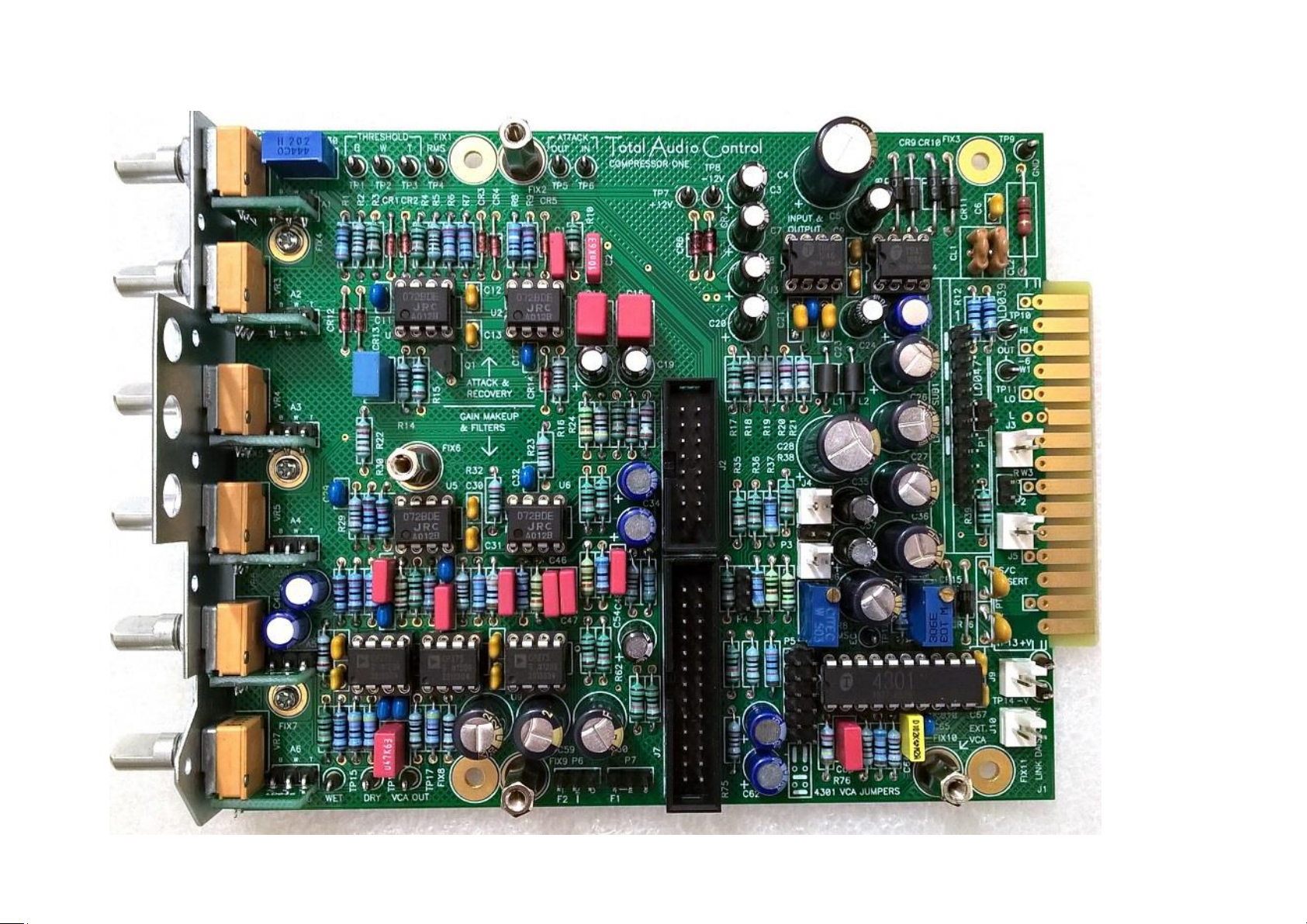
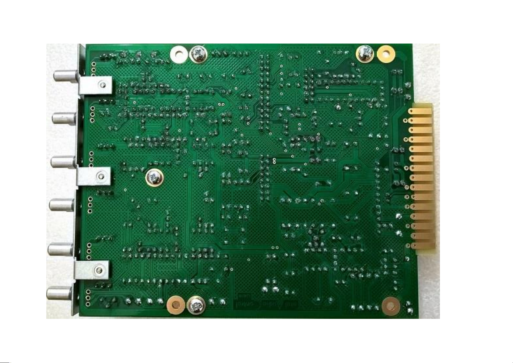
LDO66 MAIN BOARD
9
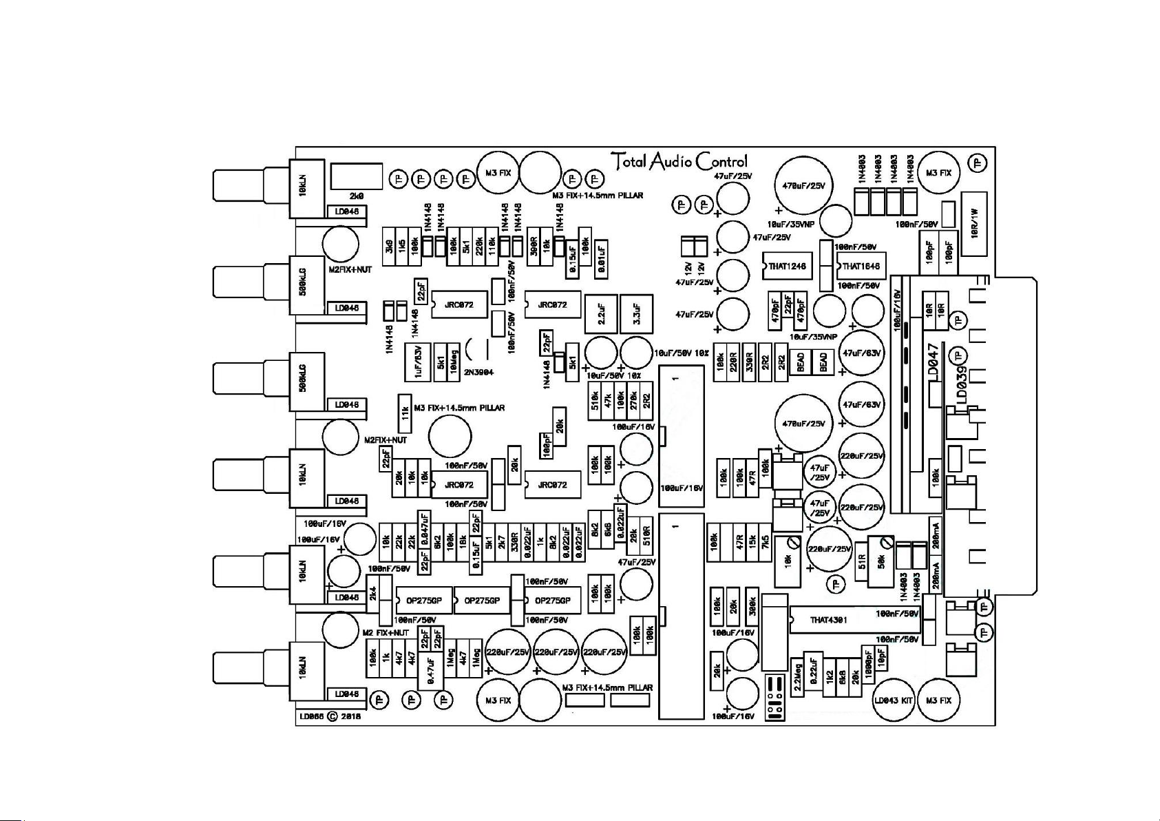
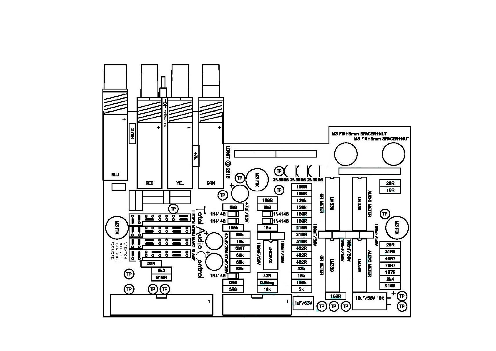
LDO66 MAIN BOARD WITH COMPONENT VALUES
10
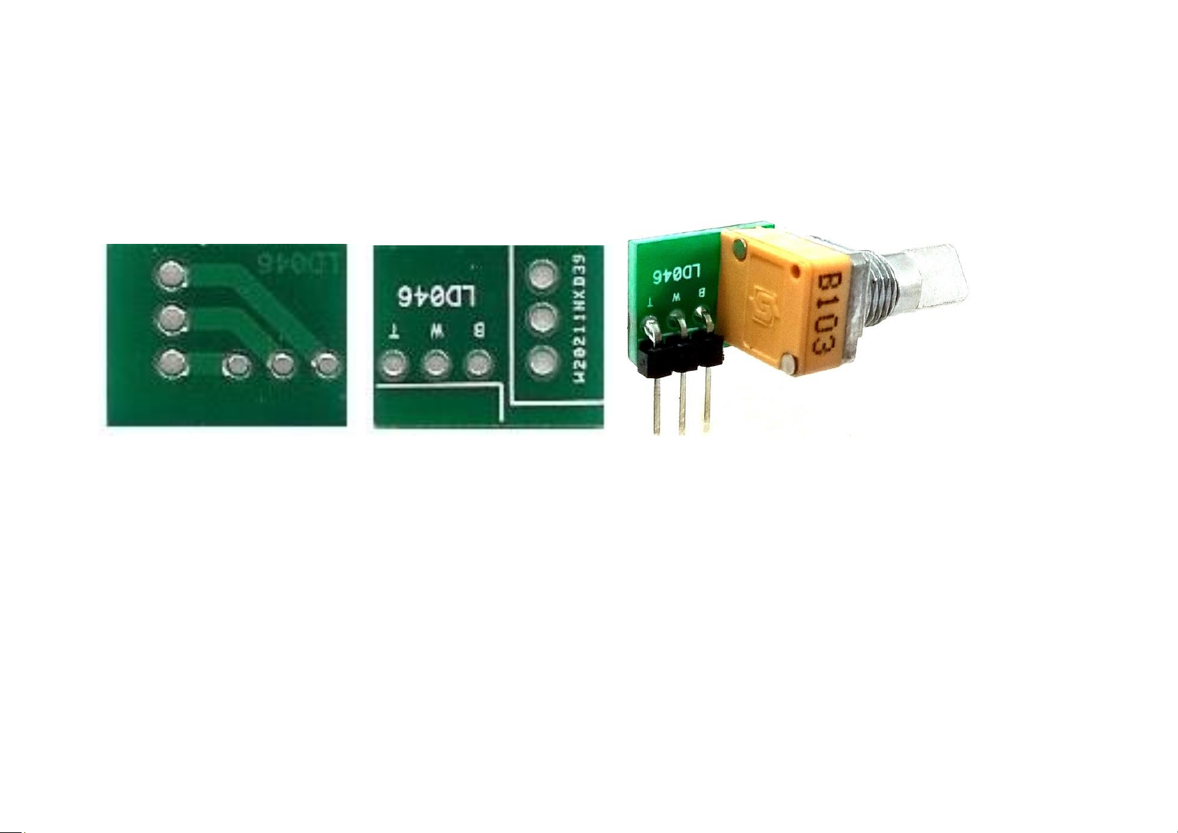
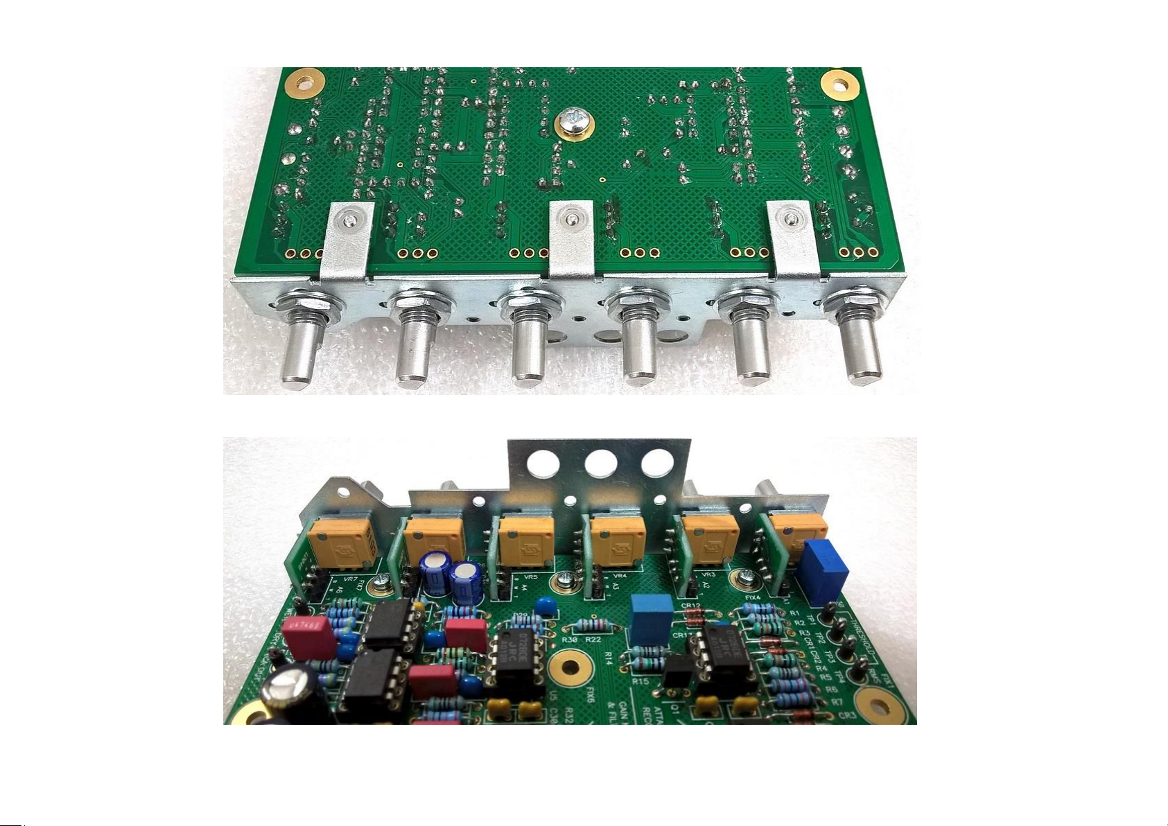
LD046 POTENTIOMETER ADAPTER CARD ASSEMBLY
Solder the 3-pin right angle header to the LD046 card. The plastic spacer should butt-up against the PCB and the header should
sit well aligned..
Solder the potentiometer. Also make sure that it is straight and at right angle.
11
12
13

14

15
16
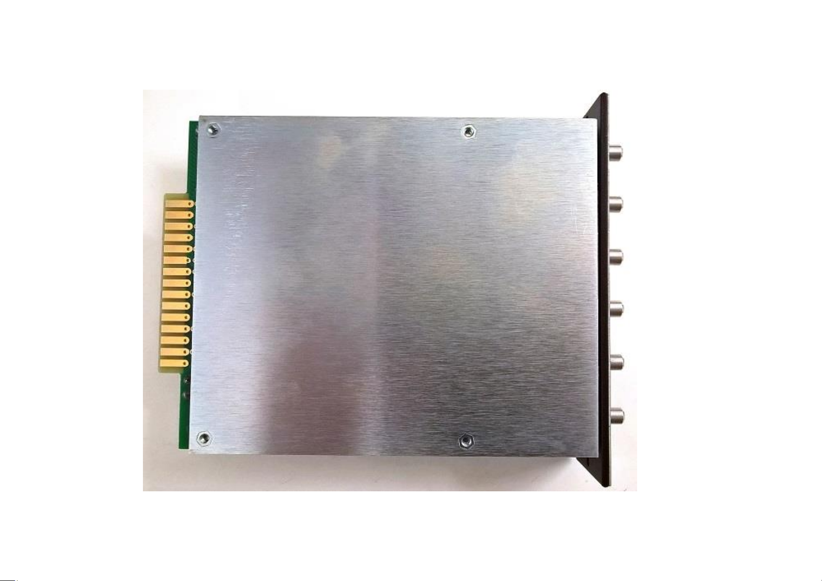
Fit the Left Hand Side screen plate.
17
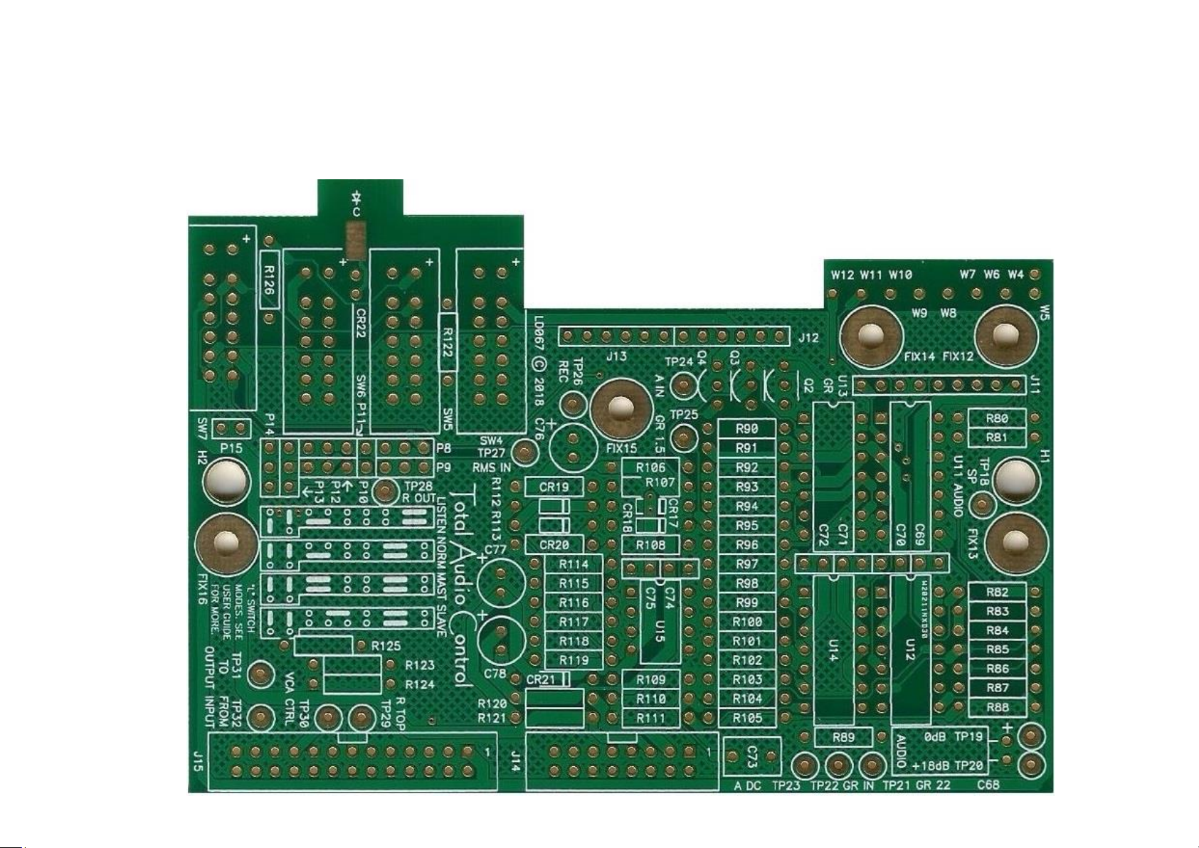
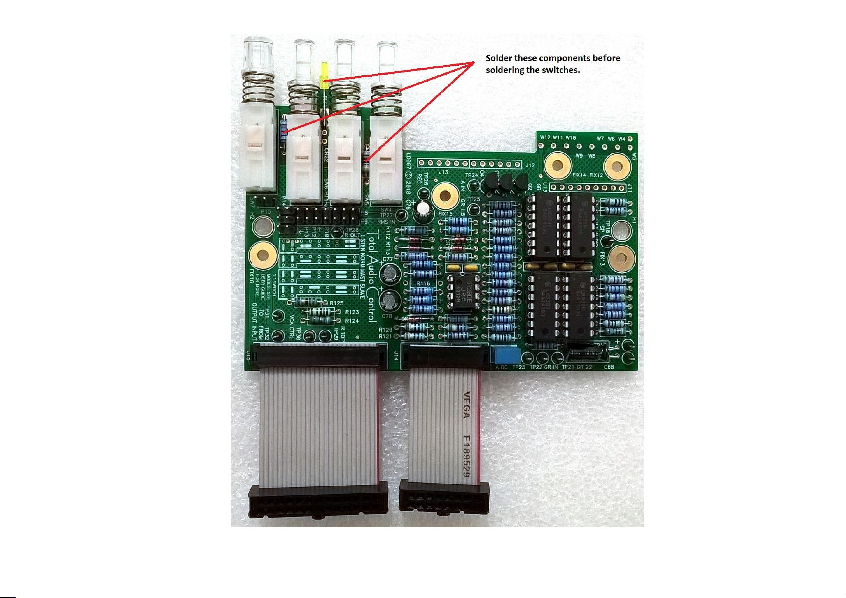
LDO67 SWITCH-SUB BOARD
18
LDO67 SWITCH-SUB BOARD WITH COMPONENT VALUES
19
20
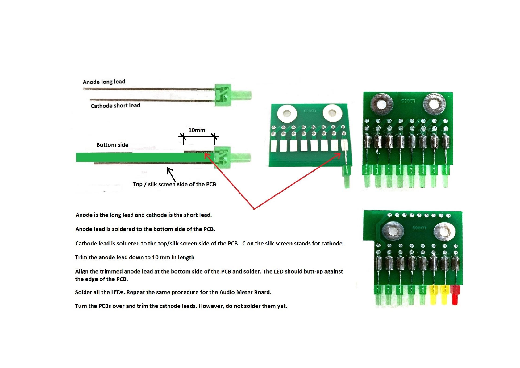
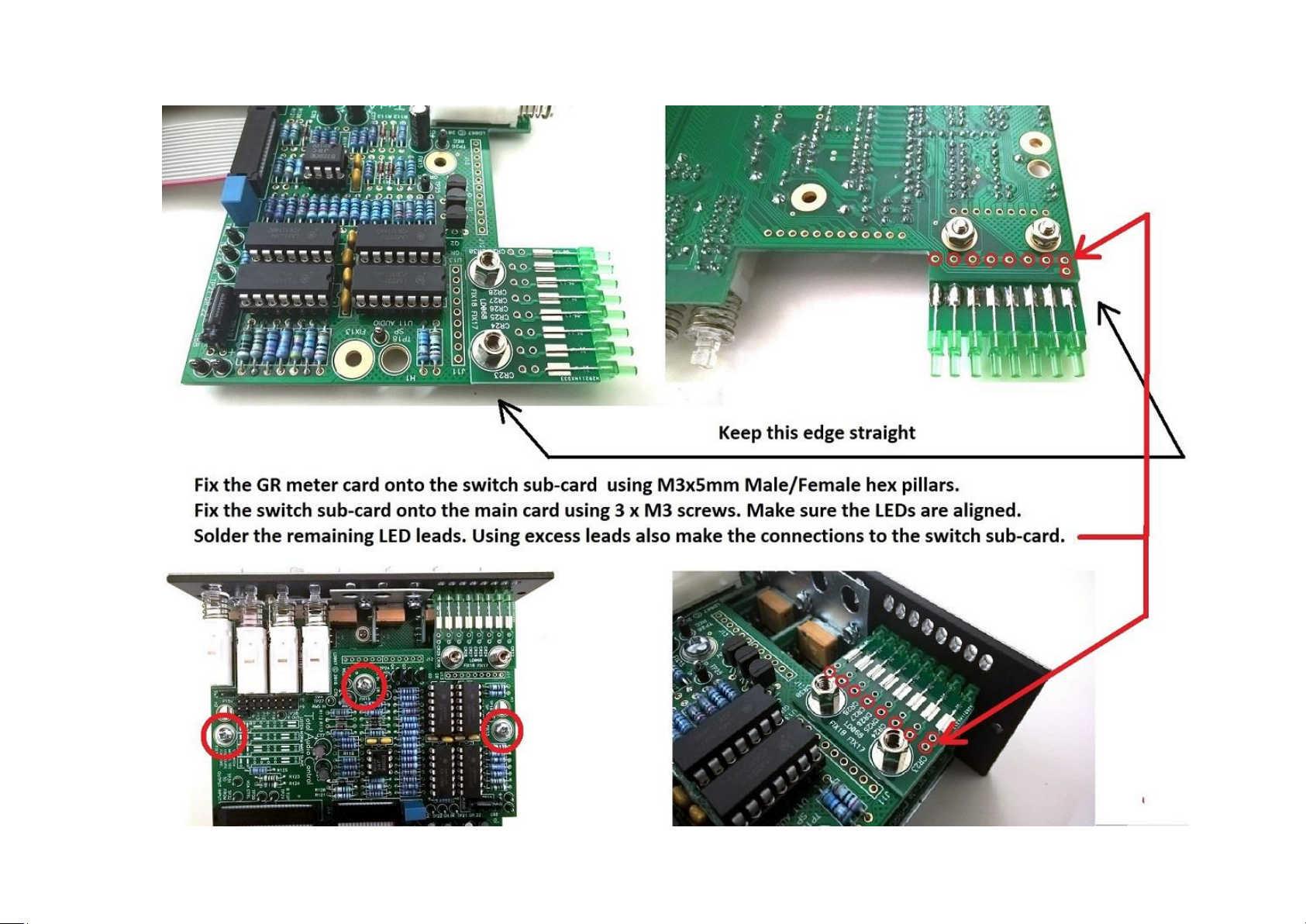
LD068 GR METER and LD069 AUDIO METER CARD ASSEMBLIES
21

22

23
LD070 TOGGLE SWITCH CARD ASSEMBLY.
1. Solder P16 and P17 2 way pin headers. Slide-off the plastic spacers. These to be interference fit for chassis connection.
2. Solder the middle switch first, and then the other two switches. Trim the excess pins.
3. Solder the 12 way pin header. Trim the excess pins.

24

25

26

27

28
Fit jumpers to SUB1 (1+2, 3+4, 6+7, 8+9) and P5/J8 as shown above. Jumper positions are also shown on the silk-screen.
DO NOT FIT ANY OTHER JUMPERS UNTIL INSTRUCTED OTHERWISE.

29
FRONT PANEL CONTROLS

30
Provides control of -30dBu to +20dBu
Provides control of 100uS to 75ms (Also active in A1 or A2 Recovery mode)
Toggle switch in R position potentiometer control of 75mS to 3S. A1: 50ms/5S. A2: 100mS/2S
Provides control of 0 to Limit (>10:1)
Provides make-up gain of -6dB to +18dB
Provides control from Fully Dry (Uncompressed) through to fully Wet (Compressed)

31
The compressor has the option to insert one of two filters in the sidechain directly before the RMS
detector and after the Insert Point/Key input.
F1 applies a high pass filter reducing the low frequencies applied to the sidechain and therefore those
frequencies are less compressed leading to a punchier bass sound.
P7: NO JUMPER. The filter has a 3dB point of 240Hz with an initial roll-off of 6dB/octave.
P7: 1-2. The filter provides a 12dB/octave slope with a 3dB point of 175Hz.
P7: 2-3. The filter has a 3dB point of 188Hz with al roll-off of 6dB/octave.
(Slope and turnover points are nominal).
THE DEFAULT SETTING IS WITH THE JUMPER ACROSS PINS 1-2.
F2 applies a band pass filter which focuses the compressor’s detection circuit entirely on the midrange
of the vocal and adds more presence. This technique also works well on bass guitar.
P6: NO JUMPER. This provides a 6dB/octave slope with 3dB points of 278Hz and 3.14 kHz.
P6: 1-2. The filter is 6dB/octave low pass only with a 3dB point of 2.76 kHz.
P6: 2-3. The filter has 3dB points of 141Hz and 2.06 kHz with al roll-off of 6dB/octave.
In all cases the low pass attenuation is limited to approx. 12dB at 10 kHz and 17dB above 100 kHz.
(Slope and turnover points are nominal).
THE DEFAULT SETTING IS WITH NO JUMPER.
Audio meter select.

32
Hard/Soft Knee select.
Feedback / Feed Forward mode select.
LINK/LISTEN. Multichannel linking or “Sidechain Listen” function.
For single/mono module operation the default mode is LISTEN.
In LISTEN mode, when the compressor is switched IN the “L” switch replaces the normal main output with
the audio signal present at the input to the RMS detector. This allows monitoring of the sidechain after the
insert point and after the filters.
“Master “LED/ LINK mode. It illuminates when a module is the “Master” of a group of modules.
In IN position the compressor is activated.

33
TESTING
SINGLE/MONO MODULE WITH LISTEN
(DEFAULT OPERATION)

34
Fit jumpers as shown above. The locations of the headers are also shown below.
PLEASE NOTE: P1 LINK JUMPER IS ONLY FITTED FOR MASTER/SLAVE OPERATION AND ONLY WHEN USED ON TOTAL AUDIO
CONTROL RACKS. IT MUST NOT BE FITTED FOR ANY OTHER MODE OF OPERATION AND/OR ON THIRD PARTY RACKS AS THIS
MAY SHORT THE CONTROL BUSSES AND CAUSE DAMAGE.

35

36
TEST PROCEDURE
1) Select the “IN” switch to be “OUT”.
2) Apply power. Check that all switches illuminate when pressed. Observe for any overheating components.
3) Check the voltages on TP13 and TP14 to ensure that power is reaching the module (+/-16V).
4) Check TP7 and TP8 to make sure that the reference voltages are correct (+/-12V).
5) With the module IN/OUT switch set to OUT, pass a +10dBu, 1kHz signal.
The AUDIO meter should indicate +10dBu for INPUT or OUTPUT and there should be no reading when the source is
selected to SIDECHAIN. The GAIN REDUCTION meter should not read.
If there is no output or the meter readings are incorrect check at TP32 (from input), TP31 (to output) and TP10 and 11
(output).
6) Set the controls as follows:
Threshold fully CW.
Attack and Release 12.00 o’clock.
Ratio fully CCW
Gain to 0dB
Dry/Wet to Dry
FF/FB to FF
Press the IN switch.
Set the input to 0dBu at 1kHz

37
7) Measure the voltage on TP4 and adjust VR8 until a reading of +85mV is obtained. This trimming is required because the
tolerance of the RMS section of the THAT4301 is +/-3dB. When RMS detectors are linked in multiple compressor setups it
is important that the 0dB reference is the same on each. Using this connection in stereo applications will prevent “image
shifting” due to one channel compressing while the other is not which can be a problem in stereo systems with
independent detectors.
The meter should now indicate 0dBu in all settings of the meter source switch and the output should be 0dBu.
8) Turn the Threshold fully CCW. All the LEDs in the GAIN REDUCTION meter should illuminate.
9) With an input of 0dB, verify the GAIN MAKEUP calibrations when fully CCW and CW (-6dB and +18dB). Also verify the 0
point is correct. Component tolerances may affect this slightly.
This has established that the Compressor is basically working.
10) Now confirm that the signals on the Test Points are close to those in the Table below with NO input signal and the
Compressor switched OUT.
Check all test points using pillar FIX6 as analogue ground reference.
Turn the Threshold knob to be exactly 12.00 o’clock.
Turn the Attack knob to be exactly 12.00 o’clock.
Turn the Recovery knob to be exactly 12.00 o’clock.
Turn the Ratio knob fully CW.
Turn the Gain knob to indicate “0”.
Turn the Dry/Wet knob fully CW.
After applying power, wait a couple of minutes before taking below measurements to allow time for voltages to settle.

38
FUNCTION
IDEAL
MEASURED
TP1
Threshold BOT (Control turned CCW)
+4.38V
+4.5V
TP2
Threshold WIP (Control at centre)
-2.774V
-2.92V
TP3
Threshold TOP (Control turned CW)
-10.14V
-9.86V
TP4
4301 RMS OUT
-450mV
-460mV
TP5
ATTACK OUT
0V
+3.86mV
TP6
ATTACK IN
0V
+4.55mV
TP7
+12V
+12V
+11.80V
TP8
-12V
-12V
-11.95V
TP9
CHASSIS
0V
0V
TP10
OUT HI
0V
+1.77mV
TP11
OUT LO
0V
+0.47mV
TP12
EC (4301 VCA control port)
0V
-0.43mV
TP13
+V
+15.8V
+15.83V
TP14
-V
-15.8V
-15.92V
TP15
WET
0V
-0.56mV
TP16
DRY
0V
-0.55mV
TP17
VCA_OUT2
0V
-1.72mV
TP18
Audio Meter SIG PRESENT
+77mV
+79.6mV
TP19
Audio Meter 0dB
+540mV
+544.1mV
TP20
Audio Meter +18dBu
+4.0V
+4.0V
TP21
GR Meter 22dB
+2.8V
+2.75V
TP22
GR Meter DC IN
0V
+1.55mV
TP23
Audio Meter Rectifier DC OUT
0V
+6mV
TP24
Audio Meter AC input
0V
-0.6mV
TP25
GR Meter 1.5dB
+191mV
+188.7mV
TP26
RECOVERY
0V
-0.58mV
TP27
4301 RMS Input from sidechain
0V
-0.59mV
TP28
RATIO control output
0V
+6.5mV
TP29
DC from sidechain to RATIO top
0V
+6.5mV
TP30
CONTROL TO VCA & MASTER BUS
0V
+6.55mV
TP31
TO OUTPUT DRIVER
0V
-0.64mV
TP32
FROM INPUT BUFFER
0V
-0.64mV

39
INPUT SIGNAL (dBu)
TP4 (measured)
NO SIGNAL
-460
-60
-309
-50
-236
-40
-170
-30
-106
-20
-43.7
-10
+18.9
0
+81.9
+10
+145.5
+20
+212.1
INPUT SIGNAL (dBu)
TP6 (measured)
-60
+4.55mV
-50
+4.53mV
-40
+4.53mV
-30
-130.7mV
-20
-1.346V
-10
-2.578V
0
-3.814V
+10
-5.067V
+20
-6.372V
13) Measure the signal at TP4 against input signal level. This is the output from the RMS converter.
14) TP6 is the output from the THRESHOLD control. The control voltage is approx. -127.45mV/dB. Therefore, to achieve 30dB
limiting with a +20dBu input signal this would need in a control voltage of 50 x 127.45 = 6.372V.
Set the input signal to +20dBu. Set the THRESHOLD CONTROL to -30dB (fully CCW). Adjust the -30 trimmer (VR1) until TP6 reads
-6.372V. This will be approximately 12 o’clock.
Next confirm that similar readings to those on TP6 are obtained on TP5 and TP29.

40
15) Trimming VCA for minimum THD (Total Harmonic Distortion)
THAT 4301 VCA symmetry can be trimmed for the lowest THD level. These are given below tables at various frequencies.
However, as it can be seen from the tables that there is not a great deal of difference between the untrimmed and trimmed
figures. Also to mention that the trimmed values will drift in time.
Therefore you may wish to leave it untrimmed.
Alternatively you may wish to install the optional LD043 VCA card containing THAT 2180 VCA which does not require trimming
as it is already laser trimmed (page 61).
For THD trimming a distortion meter, audio analyser or even a DAW with suitable plug-in can be used.
Trimming is carried out with a 1kHz input signal of +10dBu.
If a distortion meter is used, VR9 (labelled as SYM) is adjusted until a minimum value is obtained at TP12 with an unbalanced
load of 100k.

41
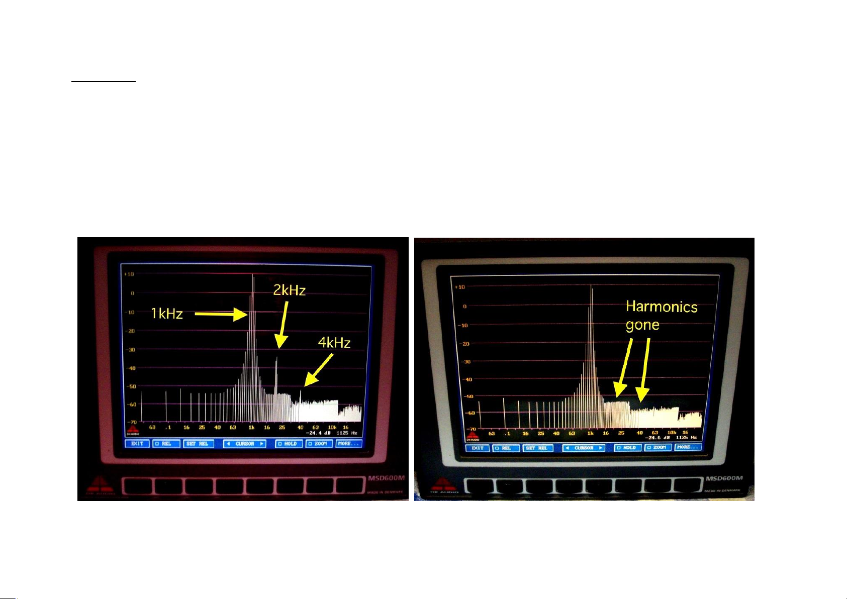
For using an audio analyser a very practical user example is given below (text and pictures courtesy of Udo Terlisten).
To trim the THD we are looking for the overtone structure which is 2 & 4 kHz (1st and 3rd overtone = 2nd and 4th harmonics) at
an injected sine wave test signal of 1kHz.
I used a Wandel & Golterman PS20 as signal generator and a DK MSD600 which was the "Ferrari" amongst all the broadcasters
and engineers in former times. It is a (multi-) level meter, a goniometer, an analyser and way more.
For Windowing I used "Nuttall" which gives the best performance in dynamic range (often used for distortion measurements).
"Hanning" works great too although it is a compromise between dynamic range and frequency selectivity.
"Hamming" might hide too much of the sought after sideband frequencies.
"3rd octave" mode doesn´t work, so FFT is best.
I crosschecked this on my iPad with "Audiotools" installed which is a cut-down version of "SMAART". One should use a good A/D
converter for these measurements. I had an "RME Babyface Pro" handy, works well.
COMPRESSOR ONE settings:
* Switch to ON
* Dry/Wet-knob fully turned CW to WET
*GAIN MAKEUP set to 0dB
* Filters set to off
* THRESHOLD fully set CW to +20dB,we don´t want the compressor start working but pass the pure audio
* RATIO set fully CCW to 1:1 (as a "precaution" only)
* ATTACK and RECOVERY do not matter as we have a static signal here. I just left them somewhere in the 12 o´clock position
42
Procedure:
* Power up COMPRESSOR ONE and let it heat up for a while
* Inject a 1kHz sine wave @ +10dBu to the input of COMPRESSOR ONE
* Now adjust VR9 (labelled "SYM") until the harmonics start to disappear.
* If you adjust VR9 further they will start to appear back again. Just make them disappear so that only the 1kHz tone is visible.
* There is a good amount of pot travel but it is easy.
* You´re done!

43
PIN
EXPECTED NOMINAL VOLTS
MEASURED
U1
1 7 0
+500mV
+0.58mV
+498mV
U2
1 7 -250mV
0
-233mV
+3.81mV
U3 5 0
-0.6mV
U4
1 8 0 0 -0.61mV
+1.54mV
U5
1 7 0 0 +1.66mV
+6.67mV
U6
1 7 0 0 +11.25mV
+1.53mV
U7
1 7 0 0 +0.75mV
-2.41mV
U8
1 7 +150mV
0
+133mV
+12.6mV
U9
1 7 +14mV
+14mV
+15.57mV
+15.26mV
U10
4
7
12
18
-450mV
0
0
0
-460mV
-0.58mV
-5.48mV
+4.48mV
U11 & U12
5
+10mV
+6.07mV
U13 & U14
5
+5mV
+1.53mV
U15
1 7
-183.6mV
+137mV
TROUBLESHOOTING:
1) TYPICAL VOLTAGES ON SELECTED IC pins using pillar FIX6 as analogue ground reference:
Compressor OUT, no input signal, Threshold, Ratio & Dry/Wet knobs CW, Attack & Recovery knobs CCW, Gain “0”, all toggle
switches to left.

44
2) NO COMPRESSION:
If the audio meter reads correctly but there is no compression there is a fault within the sidechain.
The most likely cause is that there is a break at the SIDECHAIN INSERT point.
Check all jumpers are correctly set and necessary connections are made. Connect P4 pins 1-2 to bypass insert point.
3) If TP29 does not track TP5 & TP6, suspect Q1. Q1 improves the opamp drive capability and prevents the timing capacitors
discharging back through the op-amp output impedance. Since it is within the control loop there is no voltage drop across the
base-emitter junction.

45
MULTICHANNEL OPERATION

46
THE COMPRESSOR ONE “L” SWITCH
The “L” switch can either LINK two adjacent modules for multichannel operation or can function as a SIDECHAIN LISTEN switch.
There are four basic modes of operation. Listen, Norm, Master, and Slave.
In addition to these there are two further sub modes. Master + Listen and Slave + Listen

47
1) LISTEN:
For mono compressors the “L” switch should be configured for SIDECHAIN LISTEN.
When the compressor is switched IN, the “L” switch replaces the normal main output with the audio signal present at the
input to the RMS detector. This allows monitoring of the sidechain after the insert point and after the filters. The switch is
normally latching, but if required can be made momentary by removing the latching mechanism.
2) NORM:
DO NOT CONNECT DIFFERENT MANUFACTURERS’ COMPRESSORS AS DAMAGE WILL OCCUR.
Multiple compressors are linked together and controlled by their individual controls.
The Feed-Forward/Feed-Back switch must be in the same position for ALL linked modules for correct operation.
Pressing the “L” switch connects the RMS detector capacitor to any other identical compressor using the RMS_LINK bus.
The RMS detectors within the individual THAT4301 devices are configured for true power summing to derive a control
signal that best represents the audible power of the source material. Therefore, the response of ALL compressors
connected in this manner and with their “L” switches pressed will be determined by the resulting combined control signal
which avoids image shifts in multichannel compression.
Each compressor retains full use of its individual controls.
In a stereo setup, if one signal is removed, the other output will rise by up to 3dB to maintain the constant power output.

48
INPUT dBu
COMP#1 (+V)
COMP#2 (+V)
COMP#1+#2 (+V)
OFF
0.530
0.530
0.530
-60
0.704
0.714
0.705
-50
0.774
0.782
0.775
-40
0.840
0.846
0.839
-30
0.903
0.908
0.902
-20
0.966
0.970
0.963
-10
1.028
1.031
1.025
0
1.090
1.093
1.087
+10
1.152
1.155
1.149
+20
1.215
1.220
1.212
+26
1.239
1.260
1.247
The table below compares the output onto the RMS LINK bus for two individual compressors and when both LINK
switches are pressed. When no signal is applied to the compressor the RMS output can take a while to settle to its final
value. The RMS is computed from the input signal alone after the Sidechain Insert and Filters.
This is approx. 6.2mV/dB
However, THAT advise that there is the possibility of +/-3dB variation from one device to another, although we have not
found this to be the case even when using different batches widely spaced in time.
This is not particularly important in a stand-alone device but has to be considered for multichannel setups.

49
3) MASTER:
This connects the RMS detector averaging circuit to any other identical compressor using the LINK (LINK_RMS) bus when
the switch is pressed. However, besides controlling its own VCA it also feeds the MASTER LINK BUS (LINK_MS). The
sidechain of this compressor then responds as in NORM mode but also controls all other compressors connected as
SLAVES.
THIS BUS ONLY EXISTS ON TOTAL AUDIO CONTROL RACKS, NOT THOSE OF OTHER MANUFACTURERS. FOR USE WITH
OTHER RACKS A WIRED CONNECTION IS AVAILABLE.
The RMS capacitors on adjacent modules are connected directly together to achieve a combined control signal for all the
THAT4301s in the system.
ONLY CONNECT ONE MODULE IN A GROUP AS A MASTER OTHERWISE DAMAGE WILL OCCUR.
4) SLAVE:
This connects the RMS detector averaging circuit to any other identical compressor using the LINK bus when the switch is
pressed. However, the THRESHOLD, ATTACK, RECOVERY and RATIO controls are disabled, and the compressor response is
controlled from the MASTER module set of controls.
SLAVE METERING:
When a module is configured as a SLAVE, the GAIN REDUCTION meter will display the attenuation even when the module
is not switched IN. This gives a preview of what will occur when IN is pressed. However, if IN is not pressed, the module
will not contribute to the RMS control voltage, therefore the gain reduction will change slightly when IN is pressed.

50
5) MASTER + LISTEN and SLAVE + LISTEN
In a dedicated multichannel system, it may be preferred that multiple compressors are permanently linked either in
NORM mode, or in a MASTER/SLAVE mode and that there is no need to have individual linking switches. In this instance
all L switches may be configured as LISTEN switches allowing any channel sidechain to be monitored. If required, the
latching link in the “L” switch may be removed for this application.
6) MASTER/SLAVE MODULE INTERACTION
The master module will control all dynamic functions of the slave modules. This includes THRESHOLD, ATTACK, RECOVERY
and RATIO. The makeup gain and Dry/Wet remain individually controlled on each slave.
Multiple slaves may be set up. In practice it is unlikely that more than 7 would be required.
ONLY CONNECT ONE MODULE IN A GROUP AS A MASTER OTHERWISE DAMAGE WILL OCCUR.
Pressing the L switch on a slave will connect the RMS control to the RMS bus, however until the IN switch is pressed there
will be no audio component from that SLAVE
Pressing the L switch also routes the MASTER control to the module, so the gain reduction meter will operate giving a
PREVIEW of how that SLAVE module might be affected. There is no gain reduction shown on the AUDIO OUTPUT meter as
the VCA is not switched IN.
Again, there is no contribution to the RMS bus from the module until the IN switch is pressed
Pressing the IN switch gives a contribution to the RMS bus and the gain reduction meter and audio meters respond
accordingly.

51
7) INDEPENDENT LFE COMPRESSION
If the LFE signal is required to be separately controlled, it is sufficient to choose LISTEN OR NORMAL mode of operation
and to ensure that there is a connection to the RMS capacitors on all modules via the RMS LINK bus.
8) CONTROL BUSSES
The normal link bus is a connection between the RMS capacitors on the detectors of adjacent modules. This appears on
the motherboard as LINK_RMS on pin 6.
This varies between approx. +525mV with no input signal and +1.25V with a +26dBu input between 100Hz and 20kHz..
There are slight variations with frequency at the low end : +1.234V at 10Hz and +1.24V at 20Hz.
The Master bus is the send from the master module appears on pin 6A as LINK_MASTER. This only applies to TAC
motherboards. For API style racks the link is made with a daisy-chained cable between adjacent modules. A 2-pin
connector provides this function.
The control voltage varies between approx. 0V with no input signal and -6.9V with a +26dBu sine wave input with the
RATIO set to max. THRESHOLD set to -30dB, ATTACKE and RECOVERY set at fast.
Again, there are slight variations with frequency at the low end
10Hz = -6.8V
20Hz = - 6.87V
100Hz = -6.9V
1kHz = -6.89V
20kHz = -6.89V
Under these conditions the attenuation is about 54dB corresponding to approx. 127.45dB/V.

52
9) CROSSTALK ONTO & BETWEEN CONTROL BUSSES
When a LINK switch is pressed, there is always a signal on the LINK-RMS bus and when in MASTER or SLAVE mode there
will be a signal on the LINK_MASTER bus.
When no LINK switch is pressed theses busses are floating.
There is therefore the potential for crosstalk onto these busses from the modules, or between the busses. This may be
control signals or audio signals.
Since the LINK_RMS bus is sourced from the THAT4301 timing capacitor (0.22uF) this puts a low impedance on the bus
and crosstalk onto it is not going to have adverse effects.
Similarly, when the LINK_MASTER bus is in use it will always be sourced from a low impedance.
When neither bus is in use any crosstalk onto them is immaterial.
Measured crosstalk levels were better than -40dBu under sine and pulsed input signals from 20Hz to 20kHz.
It is advisable to keep bus connection length between to a minimal length.
In the case of a multichannel compressor it is advisable to make use of the dedicated busses on the TAC rack rather than
wire link connections.
In other racks it is possible to utilise PIN 6 for the LINK _RMS and have a wire link for LINK_MASTER

53
RACK CONSIDERATIONS FOR LINKING MODULES FOR MULTICHANNEL OPERATION
Non-Total Audio Control Racks
The API 500 rack specification makes provision for only a single LINK bus (Pin 6 on the card edge connector). Although the racks
following this specification may be fitted with card edge connectors with double-row pins, these are likely to be connected
together at pin 6. Therefore, in general 500 standard racks employ a single LINK bus system.
In racks employing single LINK bus system only the NORMAL (NORM) mode of COMPRESSOR ONE can be used for multichannel
linking. PIN 6 on the solder side (left side) of the COMPRESSOR ONE module corresponds to the API 500 rack specification and
provides single LINK function. (In Total Audio Control racks this bus is called LINK_RMS bus.) This is generally a signal derived
from the time constant of the RMS converter which, when connected to an adjacent module results in a summed signal.
In racks where it is not possible to use the LINK (LINK_RMS) bus a wire from J9: A on the left-hand module to J10: A on the right
hand module can be connected in a daisy-chain manner for linking further modules as shown below.

54
On the other hand for MASTER/SLAVE operation COMPRESSOR ONE requires two signal LINK bus system (LINK_MS and
LINK_RMS). This is accomplished by external wiring through the LINK Molex connectors J9 and J10 as shown below.
However, the MASTER bus must always be wired in the same manner by using J9: B and J10: B pins.
Do not twist these wires, they may be loosely tied. They do not need screening but should be kept as short as possible while
allowing module removal.
PLEASE NOTE: When using any rack not manufactured by Total Audio Control DO NOT FIT P1 JUMPER as this might result in
LINK_RMS and LINK MASTER Busses being shorted together which could cause damage.

55
Total Audio Control racks
The Total Audio Control racks are fitted with double sided card edge connectors which are configured to allow independent
usage of the pins on row 6.
PIN 6 on the solder side of the module (left-hand side of backplane edge connector) corresponds to the API specification and
provides the LINK (LINK_RMS) function.
PIN 6A on the component side provides the LINK_MS connection.
These backplane buses may additionally be linked by a rear panel “LINK” switch.
Viewed from the rear of the rack:
3-way double pole toggle switch fitted:
Switch to the right = No linking
Switch central = only LINK_RMS linked.
Switch to the left = both LINK_RMS and LINK_MS connected.
2-way toggle double pole switch fitted:
Switch to the right = No linking
Switch to the left = both LINK_RMS and LINK_MS connected.
2-way toggle single pole switch fitted:
Switch to the right = No linking
Switch to the left = LINK_RMS connected.
(Switch must be connected across this bus).

56
SIDE CHAIN INSERT CONNECTIONS

57
PIN 7 and PIN 9 on the edge connector are unbalanced RETURN and SEND respectively.
These are labelled as W2 and W3 on the card edge connection fingers.

58
1) FOR USE IN A TOTAL AUDIO CONTROL RACK OR THIRD PARTY RACK WITHOUT INSERT POINTS.
DO NOT fit jumpers to W2 and W3.
Fit jumper to P2. This connects the SIDECHAIN INSERT SEND to INSERT RETURN, bypassing any external connection.
2) FOR USE IN A TOTAL AUDIO CONTROL RACK WITH UNBALANCED INSERT POINTS.
DO NOT fit jumpers to W2 and W3.
The LD039 EMC/ESD protection kit is required, assembled specifically for use with COMPRESSOR ONE
3) FOR USE IN A TOTAL AUDIO CONTROL RACK WITH BALANCED INSERT POINTS.
Fit wire jumpers to W2 and W3
Total Audio Control rack will be fitted with LD050 Balancing Card.
4) FOR USE IN A THIRD PARTY RACK WITH UNBALANCED OR BALANCED INSERT POINTS.
Check to make sure that PIN7 and PIN9 on the card edge connector meet insert RETURN and SEND specifications
respectively. If the specifications are met then proceed with the following.
For unbalanced connection DO NOT fit jumpers to W2 and W3. Instead LD039 EMC/ESD protection kit is required,
assembled specifically for use with COMPRESSOR ONE.

59
For balanced connection, the rack used should contain unbalanced to balanced conversion circuitries on the send and
return paths (such as Total Audio Control Balancing Card). Without this conversion balanced insert connections will
not be possible.
Also to consider that some 500 series racks use PIN 3 and PIN 11 in conjunction with PIN7 and PIN 9 on the card edge
connector to provide balanced insert connections. Again, this type of connection is not compatible with COMPRESSOR
ONE side chain insert points and will not work.
However, it might be possible to achieve unbalanced connections.
Otherwise Total Audio Control INSERT ONE module is required.
5) FOR USE IN A THIRD PARTY RACK WITHOUT INSERT POINTS BUT WITH TOTAL AUDIO CONTROL INSERT ONE MODULE.
DO NOT fit jumper to P2.
Unbalanced insert connections to INSERT ONE is made through the 2 way Molex connectors.
J3 is insert RETURN and J5 is insert SEND as shown below.
Use screened signal cable.
Please refer to INSERT ONE manual for interfacing.

60
Insert connections to Total Audio Control INSERT ONE module.

61
6) P2: SIDECHAIN INSERT POINT.
P2 is fitted if SIDECHAIN INSERT is not available. This connects the SIDECHAIN INSERT SEND to INSERT RETURN, bypassing any
external connection.
If there is any form of sidechain insert provided P2 must NOT be fitted as there may be a risk of damage to external equipment.
7) P3: DRY PATH INSERT POINT.
P3 is fitted if no DRY PATH INSERT is available. This connects the DRY PATH INSERT SEND to INSERT RETURN, bypassing any
external connection.
If there is any form of dry path insert provided P2 must NOT be fitted as there may be a risk of damage to external equipment.
8) P4: SIDECHAIN FILTER SOURCE.
P4 selects the source for the SIDECHAIN FILTER “OUT” toggle switch position to be before or after the sidechain insert point.
P4: 1-2 – Filter out pre. Insert
P4: 2-3 - Filter out post insert.

62
OPTIONAL
LD043 VCA CARD

63
The default VCA on COMPRESSOR ONE is THAT 4301 device which normally requires symmetry trimming. If symmetry trimming
is not possible then THAT 2180 device can be used by fitting LD043 card. THAT 2180 is already factory trimmed.
However, THAT 4301 is still required as it contains the RMS detector.
Symmetry TRIM control VR9 to the VCA for distortion trimming will be disabled as it is no longer required.
Do not fit jumpers to P5/J8.
Plug in the LD043 VCA card and secure it using the M3 screw supplied. As shown below.
LD043 BILL OF MATERIALS
1 LD043 PCB
R1V 4k7
R2V 1k2
R3V 5k1
R4V 20k
C1V 1000pf / 100V / 5%
CV2 10pF / 100V / NPO
CV3 100nF / 50V / X7R
CV4 100nF / 50V/ X7R
TP1V Test Point / HUGHS (Small)
U1V THAT 2181LA
U2V OP275GP
J1V 5 Way Double Row Female Header

64

65
OPTIONAL
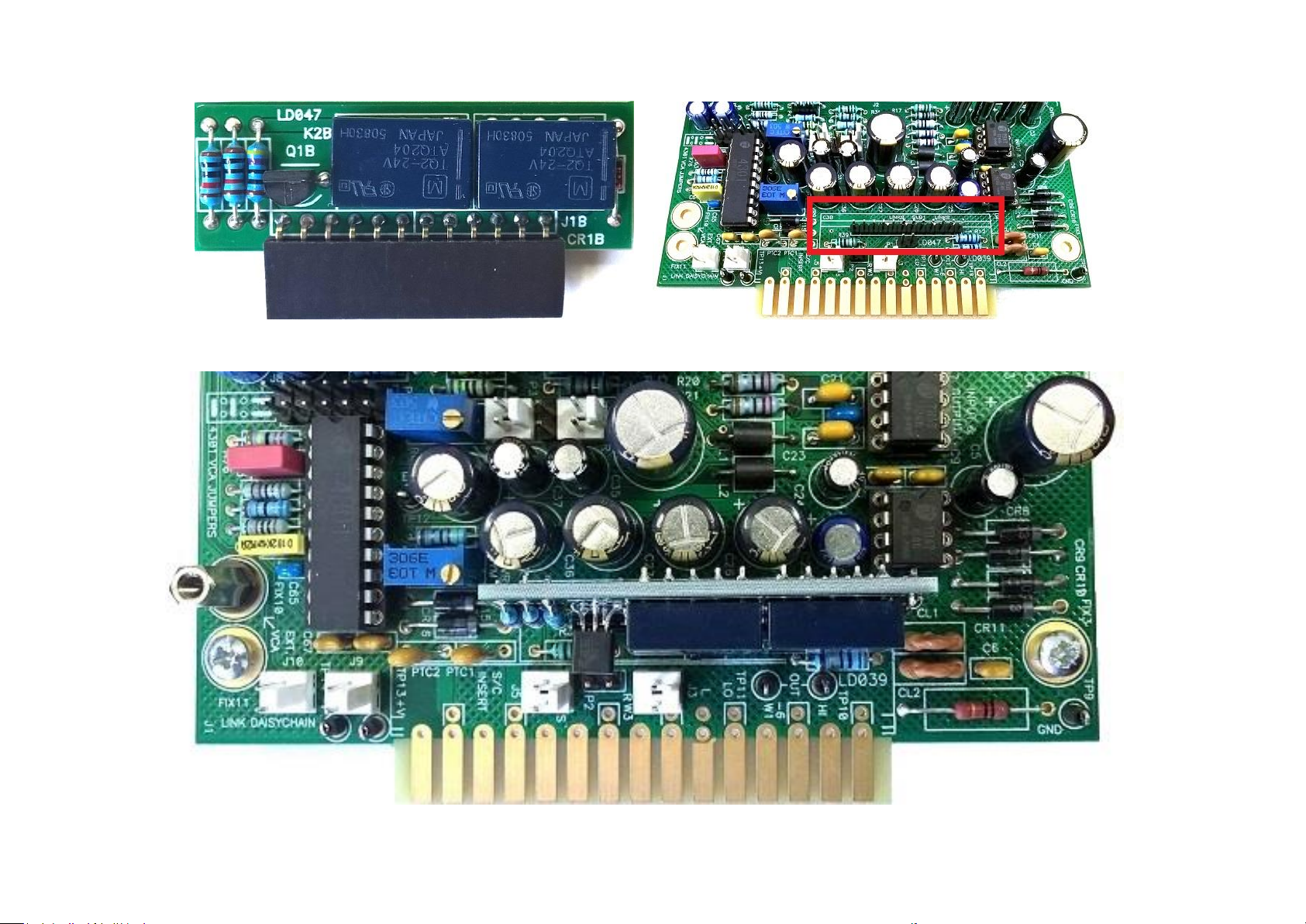
LD047 HARD BYPASS CARD

66
If hard by-pass is preferred then LD047 Hard By-Pass Card can be plugged in to SUB1 header.
ADVANTAGES
If power fails, the signal bypasses the module.
When the Compressor is switched OUT there is no deterioration of the signal path.
DISADVANTAGES
When the IN/OUT switch is used the loading signal path loading is determined by the preceding and following devices,
which could result in a mismatch or clicks.
Audio metering of the signal path on the Compressor will not be displayed.
Small clicks from relay contact bounce
LD047 BILL OF MATERIALS
1 LD043 PCB
R1B 470R
R2B 10k
R3B 10k
CR1B 1N4148
Q1B 2N3904
K1B DPDT 24V 280 Ohm Relay
K2B DPDT 24V 280 Ohm Relay
J1B 6 Way Right Angle 2.51mm pitch SIL female header
J2B 6 Way Right Angle 2.51mm pitch SIL female header
67

68
© Total Audio Control
 Loading...