

Page 1
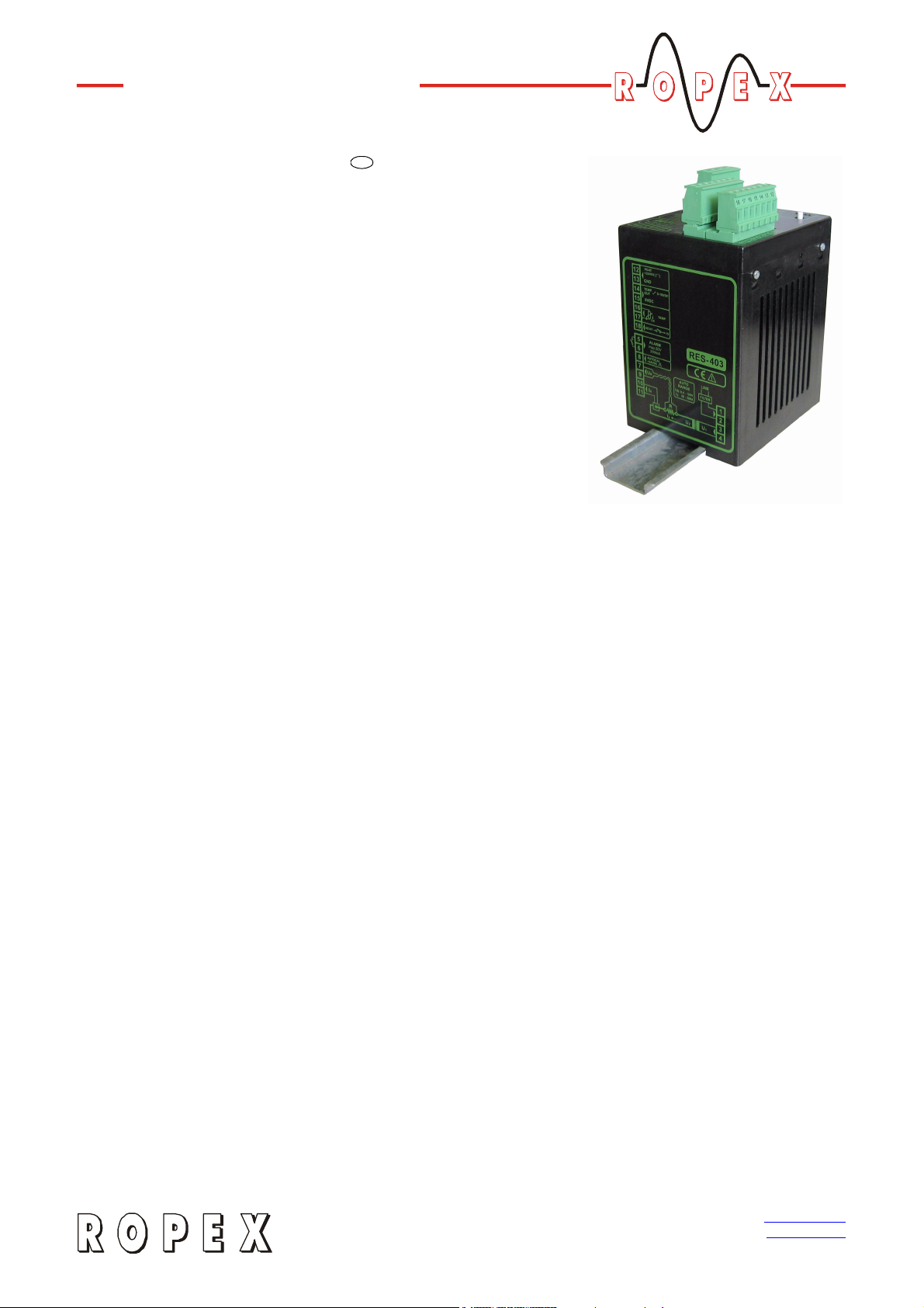
RESISTRON
GB
RES-403
Operating
Instructions
Important features
• Microprocessor technology
• Automatic zero calibration (AUTOCAL)
• Automatic optimization (AUTOTUNE)
• Automatic configuration of the secondary voltage and current ranges
(AUTORANGE, as of October 2005)
• Automatic phase angle compensation (AUTOCOMP, as of October 2005)
• Automatic frequency adjustment
• Large current and voltage range
• Set point selection with potentiometer
• 0…10VDC analog output for ACTUAL temperature
• Activated with contact or 24VDC signal
• Alarm function with fault diagnosis
• Heatsealing band alloy and temperature range selectable
26.6.06
Industrie-Elektronik GmbH Tel: +49/(0)7142/7776-0 E-Mail: info@ropex.de
Gansäcker 21 Fax: +49/(0)7142/7776-19 Internet: www.ropex.de
D-74321-Bietigheim-Bissingen (Germany) Data subject to change
Page 2

Contents
1 Safety and warning notes . . . . . . . . . . . . . . 3
1.1 Use . . . . . . . . . . . . . . . . . . . . . . . . . . . 3
1.2 Heatsealing band . . . . . . . . . . . . . . . . 3
1.3 Impulse transformer . . . . . . . . . . . . . . 3
1.4 Current transformer PEX-W2/-W3 . . . . 3
1.5 Line filter . . . . . . . . . . . . . . . . . . . . . . . 4
1.6 Warranty provisions . . . . . . . . . . . . . . . 4
1.7 Standards / CE marking . . . . . . . . . . . 4
2 Application . . . . . . . . . . . . . . . . . . . . . . . . . . 4
3 Principle of operation . . . . . . . . . . . . . . . . . 5
4 Description of the controller . . . . . . . . . . . 6
5 Accessories and modifications . . . . . . . . . 6
5.1 Accessories . . . . . . . . . . . . . . . . . . . . . 6
5.2 Modifications (MODs) . . . . . . . . . . . . . 7
6 Technical data . . . . . . . . . . . . . . . . . . . . . . . 9
7 Dimensions . . . . . . . . . . . . . . . . . . . . . . . . 11
8 Installation . . . . . . . . . . . . . . . . . . . . . . . . . 11
8.1 Installation procedure . . . . . . . . . . . . 11
8.2 Installation steps . . . . . . . . . . . . . . . . 12
8.3 Power supply . . . . . . . . . . . . . . . . . . . 13
8.4 Line filter . . . . . . . . . . . . . . . . . . . . . . 14
8.5 Current transformer PEX-W3 . . . . . . 14
8.6 Wiring diagram (Standard) . . . . . . . . 15
8.7 Wiring diagram with booster
connection (MOD 26) . . . . . . . . . . . . 16
8.8 Wiring diagram with "Temperature reached" signal (MOD 40)
or „Temp. OK“ signal (MOD 46) . . . . 17
8.9 Startup and operation . . . . . . . . . . . . 18
8.10 View of the controller . . . . . . . . . . . . . 18
8.11 Controller configuration . . . . . . . . . . . 18
8.12 Replacing and "burning in" the heat-
sealing band . . . . . . . . . . . . . . . . . . . 20
8.13 Startup procedure . . . . . . . . . . . . . . . 21
9 Controller functions . . . . . . . . . . . . . . . . . 23
9.1 Indicators and controls . . . . . . . . . . . 23
9.2 Temperature setting
(set point selection) . . . . . . . . . . . . . . 24
9.3 Temperature indication (actual value
output) . . . . . . . . . . . . . . . . . . . . . . . . 25
9.4 Automatic zero calibration
(AUTOCAL) . . . . . . . . . . . . . . . . . . . . 26
9.5 "START" signal (HEAT) . . . . . . . . . . . 27
9.6 Measuring impulse duration
(as of October 2005) . . . . . . . . . . . . . 28
9.7 Automatic phase angle
compensation (AUTOCOMP)
(as of October 2005) . . . . . . . . . . . . . 28
9.8 Temperature diagnosis
(as of October 2005) . . . . . . . . . . . . . 29
9.9 Heatup timeout
(as of October 2005) . . . . . . . . . . . . . 29
9.10 Diagnostic interface/visualization software
(as of October 2005) . . . . . . . . . . . . . 30
9.11 System monitoring/alarm output . . . . 30
9.12 Error messages . . . . . . . . . . . . . . . . . 31
9.13 Fault areas and causes . . . . . . . . . . . 36
10 Factory settings . . . . . . . . . . . . . . . . . . . . . 37
11 Maintenance . . . . . . . . . . . . . . . . . . . . . . . . 38
12 How to order . . . . . . . . . . . . . . . . . . . . . . . . 39
13 Index . . . . . . . . . . . . . . . . . . . . . . . . . . . . . . 41
Page 2 RES-403
Page 3
Safety and warning notes
1 Safety and warning notes
This RESISTRON temperature controller is
manufactured according to DIN EN 61010-1. In the
course of its manufacture it passed through quality
assurance, whereby it was subjected to extensive
inspections and tests.
It left the factory in perfect condition.
The recommendations and warning notes contained in
these operating instructions must be complied with, in
order to guarantee safe operation.
The device can be operated within the limits indicated
in the "Technical Data" without impairing its operational
safety. Installation and maintenance may only be
performed by technically trained, skilled persons who
are familiar with the associated risks and warranty
provisions.
1.1 Use
RESISTRON temperature controllers may only be used
for heating and temperature control of heatsealing
bands which are expressly suitable for them, and
providing the regulations, notes and warnings
contained in these instructions are complied with.
In case of non-compliance or use contrary to
!
the intended purpose, there is a risk that
safety will be impaired or that the heatsealing band,
electrical wiring, transformer etc. will overheat.
Ensuring such compliance is the personal
responsibility of the user.
The RESISTRON temperature controller must be set
and coded according to the temperature coefficient of
the heatsealing band.
The use of incorrect alloys with a too low
!
temperature coefficient and incorrect coding
of the RESISTRON temperature controller lead to
uncontrolled heating and ultimately to burn-out of
the heatsealing band!
The heatsealing bands that were originally supplied
must be identified by detail specification, part number
or some other means that will assure that replacement
bands are identical.
1.3 Impulse transformer
A suitable impulse transformer is necessary to ensure
that the control loop functions perfectly. This
transformer must be designed according to VDE 0570/
EN 61558 (isolating transformer with reinforced
insulation) and have a one section bobin. When the
impulse transformer is installed, suitable shock
protection must be provided in accordance with the
national installation regulations for electrical
equipment. In addition, water, cleaning solutions and
conductive fluids must be prevented from seeping into
the transformer.
Incorrect installation of the impulse
!
transformer impairs electrical safety.
1.2 Heatsealing band
A basic prerequisite for reliable and safe operation of
the system is the use of suitable heatsealing bands.
The resistance of the heatsealing band which
!
is used must have a positive minimum
temperature coefficient in order to guarantee
trouble-free operation of the RESISTRON
temperature controller.
The temperature coefficient must be specified as
follows:
TCR 104–×10 K
≥
e.g. Alloy-20: TCR = 1100 ppm/K
NOREX: TCR = 3500 ppm/K
1–
RES-403 Page 3
1.4 Current transformer PEX-W2/-W3
The current transformer supplied with the RESISTRON
temperature controller is an integral part of the control
system.
Only the original ROPEX PEX-W2 or PEX-W3
!
current transformer may be used. Other
transformers may cause the equipment to
malfunction.
The current transformer may only be operated if it is
connected to the RESISTRON temperature controller
correctly (see section 9, "Startup and operation"). The
relevant safety instructions contained in section 8.3,
"Power supply", must be obeyed. External monitoring
modules can be used in order to additionally increase
Page 4

Application
operating safety. They are not included in the scope of
supply of the standard control system and are
described in a separate document.
1.5 Line filter
The use of an original ROPEX line filter is mandatory in
order to comply with the standards and provisions
mentioned in section 1.7 "Standards / CE marking" on
page 4. This device must be installed and connected
according to the instructions contained in section 8.3,
"Power supply" as well as the separate documentation
enclosed with the line filter.
1.6 Warranty provisions
The statutory provisions for warranties apply for a
period of 12 months following the delivery date.
All devices are tested and calibrated in the factory.
Devices that have been damaged due to faulty
connections, dropping, electrical overloading, natural
wear, incorrect or negligent handling, chemical
influences or mechanical overloading as well as
devices that have been modified, relabeled or
otherwise altered by the customer, for example in an
attempt to repair them or install additional components,
are excluded from the warranty.
Warranty claims must be examined in the factory and
approved by ROPEX.
1.7 Standards / CE marking
The controller described here complies with the
following standards, provisions and directives:
DIN EN 61010-1
(VDE 0411-1)
DIN EN 60204-1 Electrical equipment of machines
EN 50081-1 EMC interference emissions
EN 50082-2 EMC interference immunity:
Compliance with these standards and provisions is only
guaranteed if original accessories and/or peripheral
components approved by ROPEX are used. If not, then
the equipment is operated on the user's own
responsibility.
The CE marking on the controller confirms that the
device itself complies with the above-mentioned
standards.
It does not imply, however, that the overall system also
fulfils these standards.
It is the responsibility of the machine manufacturer and
of the user to verify the completely installed, wired and
operationally ready system in the machine with regard
to its conformity with the safety provisions and the EMC
directive (see also section 8.3, "Power supply"). If
peripheral components (e.g. the transformer or the line
filter) from other manufacturers are used, no functional
guarantee can be provided by ROPEX.
Safety provisions for electrical
measuring, control and laboratory
devices (low voltage directive).
Overvoltage category III, pollution
severity 2, safety class II.
(machinery directive)
according to EN 55011, group 1,
class B
ESDs, RF radiation, bursts, surges.
2 Application
This RESISTRON temperature controller is an integral
part of the "Series 400", the outstanding feature of
which is its microprocessor technology. All RESISTRON temperature controllers are used to control the
temperature of heating elements (heatsealing bands,
beaded bands, cutting wires, heatsealing blades,
solder elements etc.), as required in a variety of heatsealing processes.
Page 4 RES-403
The controller is most commonly used for impulseheatsealing PE films in:
• Vertical and horizontal f/f/s machines
• Pouch, filling and sealing machines
• Film wrapping machines
• Pouch-making machines
• Group packaging machines
•etc.
Page 5

Principle of operation
The use of RESISTRON temperature controllers
results in:
• Repeatable quality of the heatseals under any conditions
3 Principle of operation
The resistance of the heatsealing band, which is temperature-sensitive, is monitored 50x per second (60x at
60Hz) by measuring the current and voltage. The temperature calculated with the help of these measurements is displayed and compared with the set point.
The primary voltage of the impulse transformer is adjusted by phase-angle control, if the measured values
deviate from the set point. The resulting change in the
current through the heatsealing band leads to a change
in the band temperature and thus also its resistance.
This change is measured and evaluated by the RESISTRON temperature controller.
The control loop is closed: ACTUAL temperature = SET
temperature. Even minute thermal loads on the heatsealing band are detected and can be corrected quickly
and precisely.
A highly high response thermo-electric control loop is
formed which is highly accurate because purely electrical variables are measured at a high sampling rate. A
high secondary current can be controlled because
power is controlled on the primary side of the transformer. This allows optimum adaptation to the load and
• Increased machine capacity
• Extended life of the heatsealing bands and teflon
coatings
• Simple operation and control of the sealing process
to the required dynamic range despite the exceptionally
compact dimensions of the controller.
PLEASE NOTE!
RESISTRON temperature controllers play a significant
role in enhancing the performance of modern
machines. However, the full benefit can only be
obtained from the advanced technology offered by this
control system if all the system components, in other
words the heatsealing band, the impulse transformer,
the wiring, the timing signals and the controller itself,
are compatible and interrelated.
We will be pleased to
contribute our many
years of experience
towards optimizing your
heatsealing system.
Heatsealing band R = f (T)
U
2
sec.
Impulse transformer
Current
transformer
U
1
prim.
RESISTRON controller
URI
R
R=f(T)
LINE
_
+
Actual value
Start
Set point
RES-403 Page 5
Indicators
and
controls
or
bus interface
Page 6

4 Description of the controller
Description of the controller
The microprocessor technology endows the RESISTRON temperature controller RES-403 with previously
unattainable capabilities:
• Very simple operation thanks to AUTOCAL, the
automatic zero calibration function.
• Good dynamic response of the control system
thanks to AUTOTUNE, which adapts automatically
to the controlled system.
• High precision thanks to further improved control
accuracy and linearization of the heatsealing band
characteristic.
• High flexibility: The AUTORANGE function (as of
October 2005) covers a secondary voltage range
from 0.4V to 120V and a current range from 30 A to
500A.
• Automatic adjustment to the line frequency in the
range from 47 Hz…63Hz.
• Increased protection against dangerous conditions,
such as overheating of the heatsealing band.
The ACTUAL temperature of the heatsealing band is
supplied to an analog 0…10VDC output. The real heatsealing band temperature can thus be displayed on an
external temperature indicator (e.g. ATR-x).
The RESISTRON temperature controller RES-403 features an integrated fault diagnosis function, which tests
both the external system (heatsealing band, wiring etc.)
and the internal electronics and outputs a selective
error message in case of a fault.
To increase operational safety and interference immunity, all 24 VDC logic signals are electrically isolated
from the controller and the heating circuit.
Coding switches on the temperature controller itself
can be used to adapt to different heatsealing band
alloys (Alloy-20, NOREX etc.) and set to the required
temperature range (0…300°C, 0…500 °C etc.).
The compact design of the RESISTRON temperature
controller RES-403 and the plug-in connections make
this controller easy to install.
5 Accessories and modifications
A wide range of compatible accessories and peripheral
devices are available for the RESISTRON temperature
controller RES-403. They allow it to be optimally
adapted to your specific heatsealing application and to
your plant's design and operating philosophy.
Analog temperature meter ATR-x
For front panel mounting or mounting on a top hat rail (DIN TS35 rail).
Analog indication of the ACTUAL temperature of the heatsealing band in °C. The
meter damping of the unit is optimized for the abrupt temperature changes that occur
in impulse mode.
Digital temperature meter DTR-x
For front panel mounting or mounting on a top hat rail (DIN TS35 rail).
Digital indication of the ACTUAL temperature of the heatsealing band in °C, with
HOLD function.
Set point potentiometer PD-x
Front panel mounting version for setting the required SET heatsealing temperature
of the RESISTRON temperature controller. The number which appears on the display corresponds to the SET heatsealing temperature in °C.
5.1 Accessories
The products described below are only a few of the
wide range of accessories available for RESISTRON
temperature controllers (ª"Accessories" leaflet).
Page 6 RES-403
Page 7
Accessories and modifications
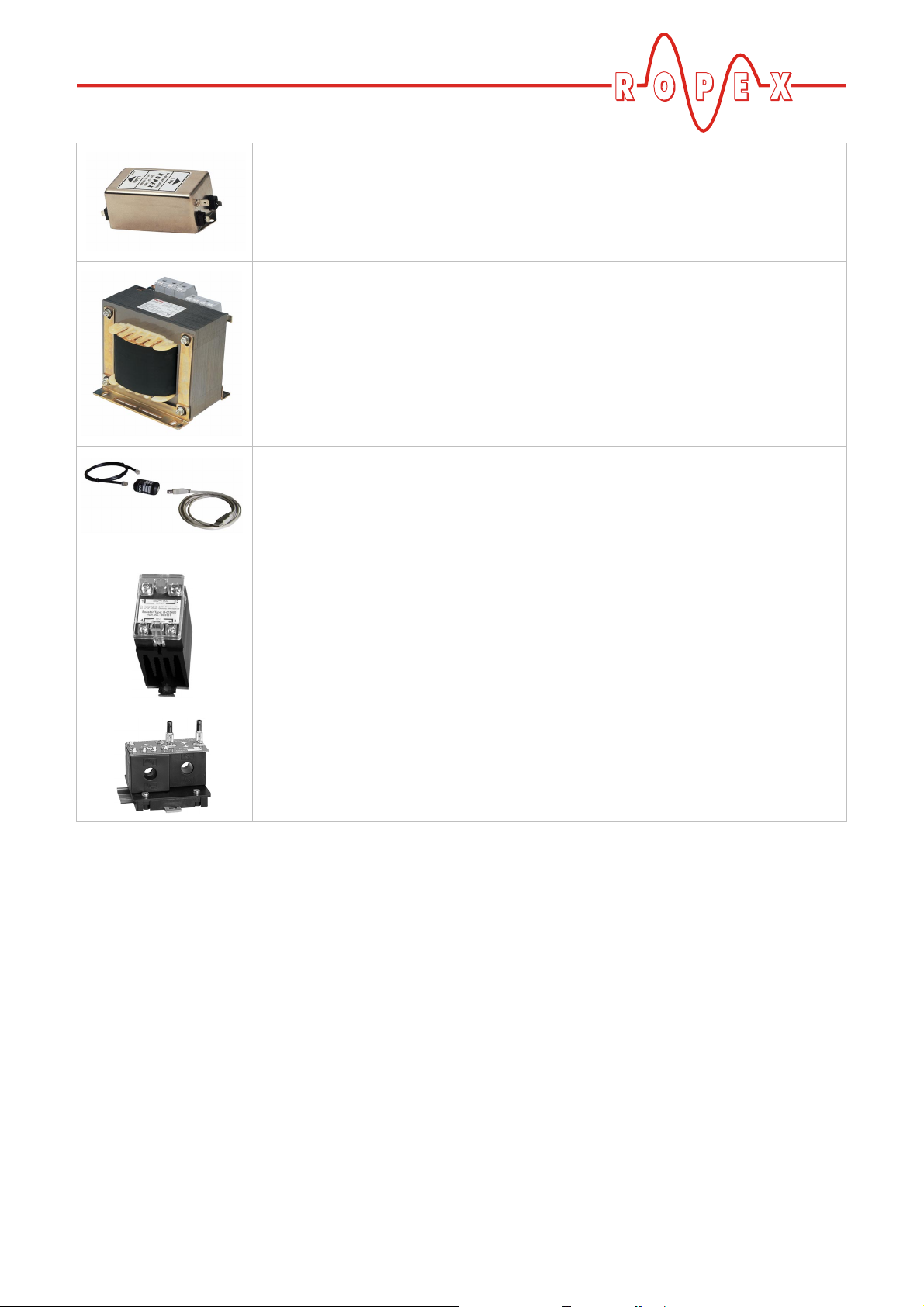
Line filter
Essential in order to ensure CE conformity.
Optimized for the RESISTRON temperature controller.
Impulse transformer
Designed according to VDE 0570/EN 61558 with a one section bobbin.
Optimized for impulse operation with RESISTRON temperature controllers.
Specified according to the heatsealing application (ª ROPEX Application Report).
Communication interface CI-USB-1
Interface for connecting a RESISTRON temperature controller with diagnostic interface (DIAG) to the PC (USB port). Associated PC visualization software for displaying setting and configuration data, and for recording SET and ACTUAL temperatures in real time.
Booster
External switching amplifier, necessary for high primary currents (continuous
current > 5 A, pulsed current > 25 A).
Monitoring current transformer
For detecting frame short-circuits on the heatsealing band.
Used as an alternative to the standard PEX-W2 current transformer.
5.2 Modifications (MODs)
Owing to its universal design, the RESISTRON temperature controller RES-403 is suitable for a very wide
range of heatsealing applications.
Various modifications (MODs) are available for the
RESISTRON temperature controller RES-403 for
implementing special applications.
The modifications described here are just a few of the
large number available. Separate documents are supplied for all modifications.
MOD 01
Amplifier for low secondary voltages
= 0.25…16VAC). This modification is necessary,
(U
R
for example, for very short or low-resistance heatsealing bands.
MOD 26
Additional terminal for connecting an external switching
amplifier (booster). This modification is necessary for
high primary currents (continuous current > 5 A, pulsed
current > 25A).
RES-403 Page 7
Page 8
Accessories and modifications
MOD 40
Additional terminal for "Temperature reached" signal.
This output signal is activated when the ACTUAL
temperature of the heatsealing band exceeds 95 % of
the SET heatsealing temperature. It can be used to
monitor the process, for example, or to control the
closure of the heatsealing bars.
MOD 40 cannot be used in combination with
!
MOD 26 (booster connection) manufactured
prior to September 2005.
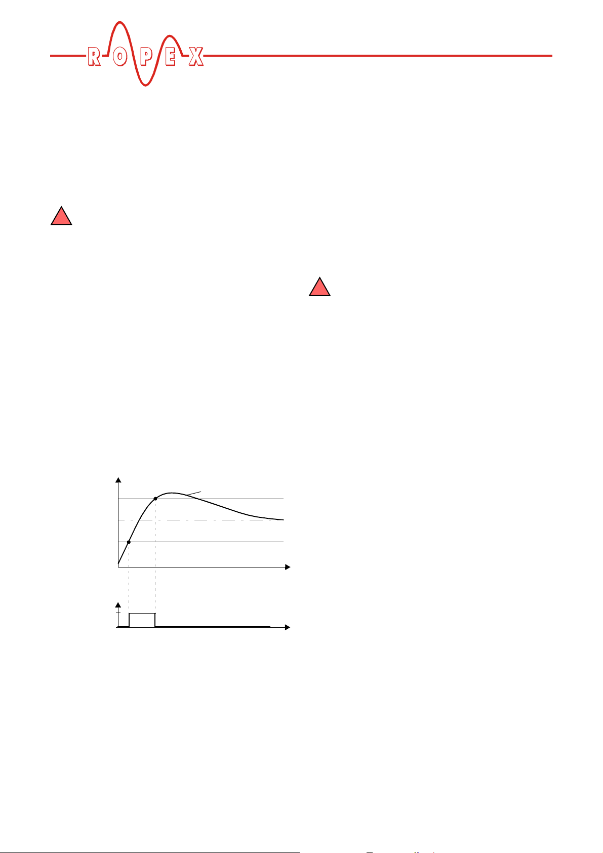
MOD 46 (as of October 2005)
Additional terminal for "Temperature OK" signal. If this
modification is installed, the RES-403 checks whether
the ACTUAL temperature is within a settable tolerance
band ("OK" window) on either side of the SET
temperature. The lower ( ) and upper
∆ϑ
( ) tolerance band limits are configured in the
upper
factory to -10 K and +10 K. These values can be set
independently of one another in the ROPEX
visualization software (ª section 9.10 "Diagnostic
interface/visualization software (as of October 2005)"
on page 30).
If the actual temperature is inside the specified
tolerance band when the "START" signal is activated,
the output signal is activated as well (see graph below):
∆ϑ
lower
If the actual temperature leaves the tolerance band, the
output signal is deactivated again. The output signal
then remains deactivated, even if the actual temperature subsequently returns to the tolerance band.
It is thus possible to check - as part of the monitoring
concept, for instance - whether the output signal is still
active at the end of the heatsealing process, in other
words whether the actual temperature has remained
within the defined tolerance band throughout the entire
process.
The output signal is not deactivated again until the next
"START" signal is activated or until an alarm is
signaled.
MOD 46 ("Temperature OK" signal) cannot be
!
used in combination with MOD 40
("Temperature reached" signal).
Set+∆ϑ
Set+∆ϑ
Signal
„Temp. OK“
Not conduct.
upper
Set
lower
Conductive
Actual value
Time
Time
Page 8 RES-403
Page 9
Technical data
6 Technical data
Type of construction Housing for installation in the electrical cabinet
Snaps onto a standard top hat rail (DIN TS35 rail, 35 mm) acc. to DIN EN 50022
Dimensions: 90 x 75 mm; height: 135 mm (incl. terminals)
Line voltage All controllers manufactured as of October 2005:
115VAC version: 110VAC -15 %…120VAC +10% (equivalent to 94…132 VAC)
230VAC version: 220VAC -15 %…240VAC +10% (equivalent to 187…264VAC)
400VAC version: 380VAC -15 %…415VAC +10% (equivalent to 323…456VAC)
All controllers manufactured as of January 2004 up to September 2005:
115VAC version: 115VAC -15 %…120VAC +10% (equivalent to 98…132 VAC)
230VAC version: 230VAC -15 %…240VAC +10% (equivalent to 196…264VAC)
400VAC version: 400VAC -15 %…415VAC +10% (equivalent to 340…456VAC)
All controllers manufactured up to December 2003:
115VAC, 230 VAC or 400VAC, tolerance: +10% / -15 %
depending on version selected (ª section 12 "How to order" on page 39)
Line frequency 47…63Hz, automatic adjustment to frequencies in this range
Heatsealing band
type and temperature
range
All controllers manufactured as of October 2005:
The temperature range and temperature coefficient settings can also be specified
by means of the ROPEX visualization software (ª section 9.10 "Diagnostic
interface/visualization software (as of October 2005)" on page 30) in addition to
the rotary coding switch (see below):
Temperature range: 200°C, 300 °C, 400 °C or 500°C
Temperature coefficient: 400…4000 ppm (variable setting range)
Five different ranges can be set on the controller with a rotary coding switch:
Temperature coefficient 1100ppm, 0…300°C (e.g. Alloy-A20), default
Temperature coefficient 780 ppm, 0…300°C (e.g. Alloy L)
Temperature coefficient 1100ppm, 0…500°C (e.g. Alloy-A20)
Temperature coefficient 780 ppm, 0…500°C (e.g. Alloy L)
Temperature coefficient 3500ppm, 0…300 °C (e.g. NOREX)
The settings for a temperature coefficient of 780 ppm are only available on controllers manufactured as of October 2003.
Set point selection
Terminals 16+17
With an external PD-3 or PD-5 precision potentiometer (R = 2kΩ)
0…2kΩ, equivalent to 0…300°C or 0…500 °C
Analog output
(actual value)
Terminals 14+15
Digital logic levels
Terminals 8, 12, 13
Digital logic levels
„Temp. OK“ signal
(MOD 40)
0…10VDC, Imax = 5 mA
Equivalent to 0…300 °C or 0…500°C
Accuracy: ±1% add. 50mV
LOW (0V): 0…2 VDC
HIGH (24VDC): 12…30 VDC (max. current input 6mA)
Reverse polarity-protected
=30VDC
U
max
=50mA
I
max
U
< 2V (saturation voltage)
ON
RES-403 Page 9
Page 10
Technical data
Alarm relay U
Maximum load
(primary current of
=50VDC, I
max
I
= 5A (duty cycle = 100%)
max
= 25A (duty cycle = 20 %)
I
max
max
= 0.2A, potential-free
impulse
transformer)
Power dissipation max. 20W
Ambient
+5…+45°C
temperature
Degree of protection IP20
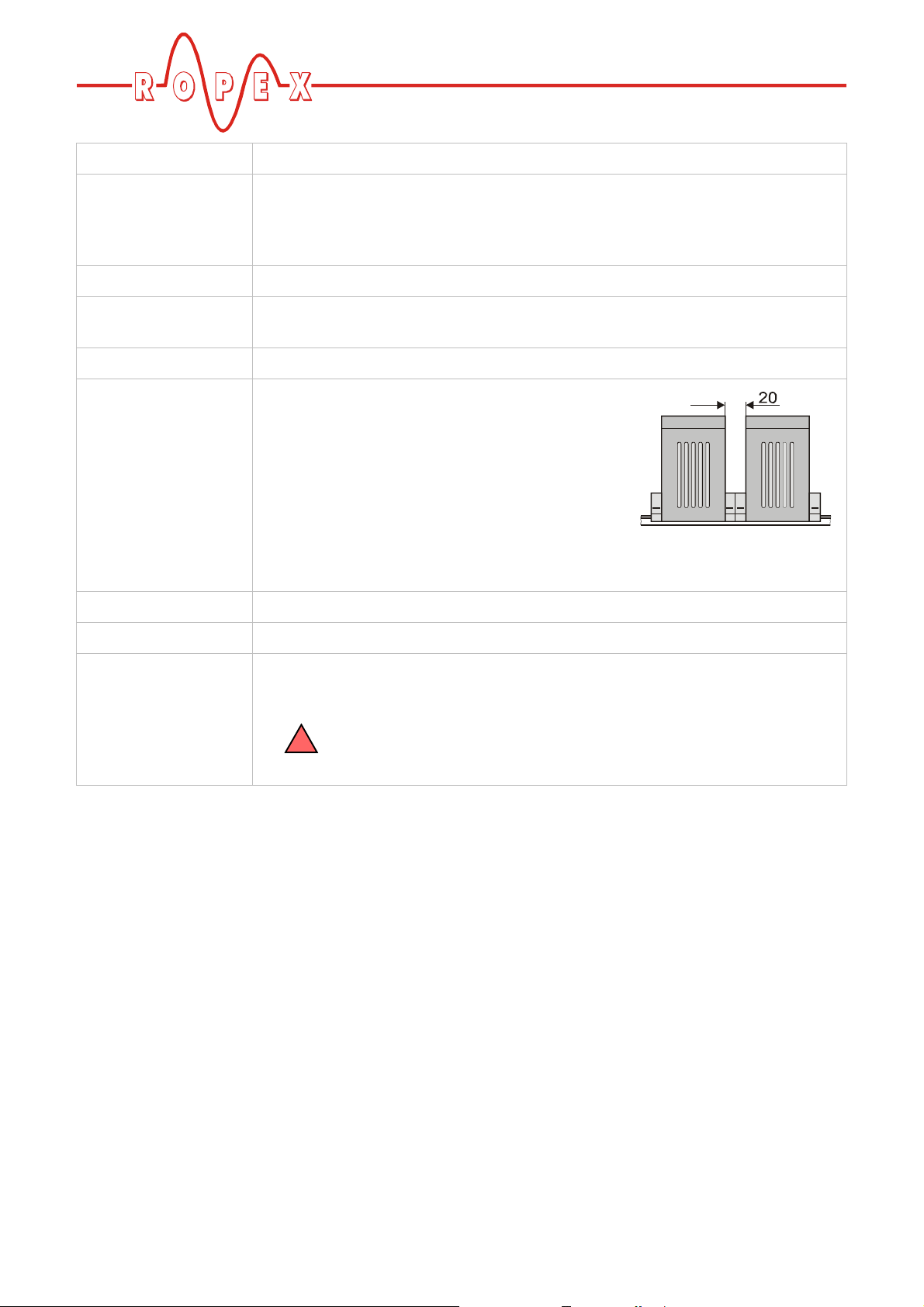
Installation If several controllers are installed on one top hat
rail (DIN TS35 rail), a clearance of at least 20mm
should be allowed between them.
The moving clip required for fastening must be
facing down for mounting on a horizontal top hat
rail.
End holders to mechanical fix the controller must be fitted at both ends for mounting on a vertical top hat rail.
Weight Approx. 0.7 kg (incl. connector plug-in parts)
Housing material Plastic, polycarbonate, UL-90-V0
Connecting cables
Type / cross-sections
Rigid or flexible; 0.2…2.5mm² (AWG 24…12)
Plug-in
If ferrules are used, they must be crimped in accordance
!
with DIN 46228 and IEC/EN 60947-1.
This is essential for proper electrical contact in the terminals.
Page 10 RES-403
Page 11
Dimensions
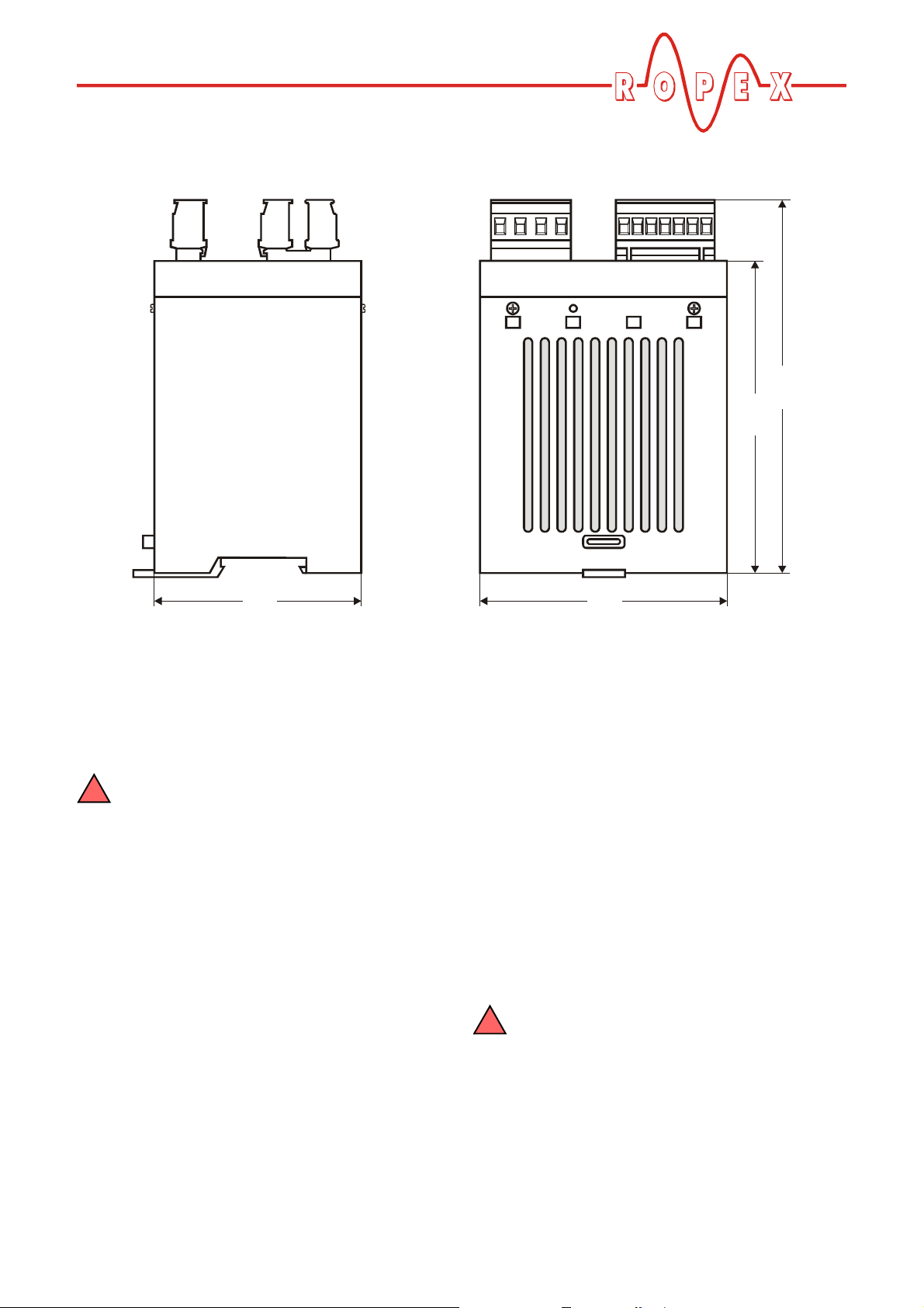
7 Dimensions
135.0
113.0
75.0 90.0
8 Installation
ª See also section 1 "Safety and warning notes" on
page 3.
Installation and startup may only be per-
!
formed by technically trained, skilled persons who are familiar with the associated risks and
warranty provisions.
8.1 Installation procedure
Proceed as follows to install the RESISTRON temperature controller RES-403:
1. Switch off the line voltage and verify that the circuit
is de-energized.
2. The supply voltage specified on the nameplate of
the RESISTRON temperature controller must be
identical to the line voltage that is present in the
plant or machine. The line frequency is automatically detected by the RESISTRON temperature
controller in the range from 47Hz…63 Hz.
3. Install the RESISTRON temperature controller in
the electrical cabinet on a standard top hat rail (DIN
TS35 rail, according to DIN EN 50022). If several
controllers are installed on one top hat rail, the
minimum clearance specified in section 6 "Technical
data" on page 9 must be allowed between them.
4. Wire the system in accordance with the instructions
in section 8.3 "Power supply" on page 13,
section 8.6 "Wiring diagram (Standard)" on page 15
and the ROPEX Application Report. The information
provided in section 8.2 "Installation steps" on
page 12 must also be heeded additionally.
Check the tightness of all the system connec-
!
tions, including the terminals for the impulse
transformer windings.
5. Make sure that the wiring conforms to the relevant
national and international installation regulations.
RES-403 Page 11
Page 12

8.2 Installation steps
Installation
Heatseal element
with coppered ends
Sufficient wire
cross-section
Avoid long
cables
Dimension
transformer correctly
- Secondary voltage
- Power
- Duty cycle
F
U (sec.)
2
Heatsealing band R= f (T)
No additional
resistance
in secondary
circuit
A
Impulse
transformer
Use heatseal bands with
suitable temperature coefficient
Note
number
of turns
Current transformer
U (prim.)
1
20mm clearance if several
controllers installed on
PEX-W2/-W3
Temperature
meter
ATR -x
Note
polarity
one top hat rail
Controller
No
push-on
connectors
Connect U measuring
heatsealing band ends
Twi sted
Current measuring
R
wires directly to
wires I
R
Line
Line filter
LF-xx480
Note
direction
of rotation
Digital
potentiometer
PD-x
Configure
DIP switches
correctly
(up to Sept. 2005)
Page 12 RES-403
Page 13

Installation
8.3 Power supply
L1
(L1)
N(L2)
GND/
Earth
ON
OFF
Short wires
1
LINE
Ka
U
K1
I
2
R
R
I
>
3
LINE
FILTER
ROPEX
temperature
controller
U
1
PRIM.
U
2
SEC.
R
Line
115VAC, 230 VAC, 400VAC
Circuit breaker
Double-pole, C characteristic
(ª ROPEX Application Report)
I
>
3
Kb
3
2
Short-circuit protection only.
!
RESISTRON temperature controller not protected.
Relay Ka
For "HEAT ON - OFF" function (all-pole) or
"EMERGENCY STOP".
Line filter
The filter type and size must be determined according to
the load, the transformer and the machine wiring
(ª ROPEX Application Report).
Do not run the filter supply wires (line side) parallel
!
to the filter output wires (load side).
RESISTRON temperature controller belonging to the
4xx Series.
Relay Kb
Load break (all-pole), e.g. in combination with the alarm
output of the temperature controller.
When using a series resistor RV-....-1 the relay Kb
!
shall be installed.
Impulse Transformer
Designed according to VDE 0570/EN 61558 (isolating
transformer with reinforced insulation). Connect core to
ground.
Use transformers with a one section bobbin. The
!
power, duty cycle and voltage values must be deter-
mined individually according to the application (ª ROPEX
Application Report and "Accessories" leaflet for impulse
transformers).
Wiring
The wire cross-sections depend on the application
(ª ROPEX Application Report).
Guide values:
Primary circuit: min. 1.5mm², max. 2.5 mm²
Secondary circuit: min. 4.0 mm², max. 25 mm²
c These wires must always be twisted (>20/m)
d These wires must be twisted (>20/m) if several control
loops are laid together ("crosstalk").
e Twisting (>20/m) is recommended to improve EMC.
RES-403 Page 13
Page 14

Installation
8.4 Line filter
To comply with EMC directives – corresponding to
EN 50081-1 and EN 50082-2 – RESISTRON control
loops must be operated with line filters.
These filters damp the reaction of the phase-angle control on the line and protect the controller against line
disturbances.
The use of a suitable line filter is part of the
!
standards conformity and a prerequisite of
the CE mark.
ROPEX line filters are specially optimized for use in
RESISTRON control loops. Providing that they are
Large cross-section
wire to ground
PE
LINE
installed and wired correctly, they guarantee compliance with the EMC limit values.
You can find the exact specification of the line filter in
the ROPEX Application Report calculated for your particular heatsealing application.
For more technical information: ª "Line filter" documentation.
It is permissible to supply several RESIS-
!
TRON control loops with a single line filter,
providing the total current does not exceed the
maximum current of the filter.
The wiring instructions contained in section 8.3 "Power
supply" on page 13 must be observed.
max. 1m
ROPEX
temperature
controller
Do not lay parallel
Large cross-section
wire to ground
Large frame contact surface
8.5 Current transformer PEX-W3
The PEX-W3 current transformer supplied with the
RESISTRON temperature controller is an integral part
24
23
terminal
wires
60
39
26
14
Mounting plate (galvanized)
of the control system. The current transformer may only
be operated if it is connected to the temperature controller correctly (ª section 8.3 "Power supply" on
page 13).
28
75
12
14
terminal
block
Snap-on for DIN-rail 35 x 7,5mm or 35 x 15mm (DIN EN 50022)
Page 14 RES-403
Page 15

Installation
8.6 Wiring diagram (Standard)
NOTE:
AUTOCAL button
also provided on
controller
AUTOCAL
with 24VDC signal
ALARM
OUTPUT
max. 50V/0,2A
START (HEAT)
with
24VDC signal
GND 13
Ground
for 24VDC signals.
Must be grounded
externally to prevent
electrostatic
charging!
START (HEAT)
with contact
_
ATR
°C
+
ANALOG
OUTPUT
+0...10VDC
Cable shielded
cw
2K
SET POINT
POTENTIOMETER
PD-3 or PD-5
(also with MOD 01)
8
6
5
Contact closed or
opened by ALARM
(see configuration)
12
18
15
14
16
0V
(Internnal ground)
17
No external
grounding allowed!
RES-403
(Internal ground)
No external
grounding allowed!
until
productions
date
09.05
(Internal ground)
No external
grounding allowed!
0V
0V
1
2
3
4
Impuls
transformer
7
U
R
9
10
11
twisted
I
R
Current transformer
PEX-W2/-W3
Line filter LF-xx480
LINE
U
1
prim.
U
2
sec.
Heat-
R
sealing
band
RES-403 Page 15
Page 16

8.7 Wiring diagram with booster
connection (MOD 26)
Installation
NOTE:
AUTOCAL button
also provided on
controller
AUTOCAL
with 24VDC signal
ALARM
OUTPUT
max. 50V/0,2A
START (HEAT)
with 24VDC signal
GND 13
Ground
for 24VDC signals.
Must be grounded
externally to prevent
electrostatic
charging!
START (HEAT)
with contact
_
ATR
°C
+
ANALOG
OUTPUT
+0...10VDC
Cable shielded
cw
2K
SET POINT
POTENTIOMETER
PD-3 or PD-5
(also with MOD 01)
8
6
5
Contact closed or
opened by ALARM
(see configuration)
12
18
15
14
16
0V
(Internnal ground)
17
No external
grounding allowed!
RES-403
(Internal ground)
No external
grounding allowed!
until
productions
date
09.05
(Internal ground)
No external
grounding allowed!
0V
0V
1
2
Booster
20
IN OUT
19
NC
3
NC
4
7
U
R
9
10
I
R
11
Current transformer
13
24
Impuls
transformer
twisted
PEX-W2/-W3
Line filter LF-xx480
LINE
U
1
prim.
U
2
sec.
Heat-
R
sealing
band
Page 16 RES-403
Page 17

Installation
A
1
2
3
4
Additional terminals
in housing cover
for MOD 26 (Booster connection)
ALARM
HEAT
OUTPUT
UTOCAL
BOOSTER
MOD 26 cannot be used in combination with
!
MOD 40 ("Temperature OK" signal)
manufactured up to September 2005.
19 20
8.8 Wiring diagram with "Temperature reached" signal (MOD 40)
or „Temp. OK“ signal (MOD 46)
+24VDC
+24VDC
RES- 403
+
I
max. 50mA
GND
MOD 40 cannot be used in combination with
! !
MOD 26 (booster connection) manufactured
prior to September 2005.
GND
1
2
3
4
Additional terminals
in housing cover
for MOD 40 (”Temp. reached” signal)
or MOD 46 (”Temp. OK” signal)
MOD 46 cannot be used in combination with
MOD 40.
ALARM
HEAT
OUTPUT
AUTOCAL
RES-403 Page 17
Page 18

8.9 Startup and operation
8.10 View of the controller
Terminals
Wiring diagramm
Installation
LEDs
Button for
AUTOCAL function
Nameplate
8.11 Controller configuration
The controller must be switched off in order
!
to configure the coding switches and plug-in
jumpers.
8.11.1 Configuration of the DIP switches
for secondary voltage and current
Automatic configuration (AUTORANGE)
(as of October 2005)
The secondary voltage and current ranges are
automatically configured by the automatic calibration
function (AUTOCAL). The voltage is configured in the
range from 0.4 VAC to 120VAC and the current in the
Coding switches and
plug-in jumpers
range from 30 A to 500A. If the voltage and/or the
current is outside the permissible range, a detailed
error message appears on the controller (ª see
section 9.12 "Error messages" on page 31).
Configuration with coding switches
(up to September 2005)
Set the DIP switches for matching the secondary
voltage U
position for your application.
!
Report calculated for your particular application.
and the secondary current I2 to the correct
2
You can find the exact configuration of the
DIP switches in the ROPEX Application
Page 18 RES-403
Page 19

Installation
F
F
O
1-10
)
V
2
ON
U (
3
4
SWITCH
5
4
3
2
1
F
F
O
N
O
O
2
1
N
U
2
1...10V
3
6...60V
20...120V
If the secondary current I2 is less than 30A, the
PEX-W2 or PEX-W3 current transformer must have
two turns (ª ROPEX Application Report).
2x
Factory settings
4
5
DIP switch DIP switch
12
OFF
ON
OFF
OFF
ON
OFF
3
OFF
OFF
ON
I
2
30...100A
60...200A
120...400A
4
OFF
ON
ON
5
OFF
OFF
ON
8.11.2 Configuration of the rotary coding
switch for the temperature range
and alloy
Switch
position
0
1
4
5
8
9 PC-CONFIGURATION
0 = Factory settings
The settings for a temperature coefficient of
!
780ppm (switch position 1 and 5) are only
available on controllers manufactured as of
October 2003.
Te mp .
range
300°C
300°C
500°C
500°C
300°C
Te mp .
coefficient
1100ppm/K
780ppm/K
1100ppm/K
780ppm/K
3500ppm/K
Band
alloy
e.g. Alloy-20
e.g. Alloy L
e.g. Alloy-20
e.g. Alloy L
e.g. NOREX
0
1
9
2
8
3
7
4
6
5
0
1
4
5
8
9
TEMP. RANGE
300°C
300°C
500°C
500°C
300°C
PC CONFIGURATION
SWITCH POS.
0
1
9
2
8
3
7
4
6
5
ALLOY
1100ppm/K
780ppm/K
1100ppm/K (A20)
780ppm/K
3500ppm/K
(A20)
(L)
(L)
(NOREX)
If the switch is set to "9" (as of October 2005), more
temperature ranges and alloys can be selected by
means of the ROPEX visualization software (ª see
section 9.10 "Diagnostic interface/visualization software (as of October 2005)" on page 30).
RES-403 Page 19
Page 20

8.11.3 Configuration of the alarm relay
Installation
Alarm relay contact
opened by alarm/
PC-CONFIGURATION.
Alarm relay contact
closed by alarm.
(factory setting)
If the plug-jumper is not inserted - or if it is
!
incorrectly inserted - an error message
appears when the controller is switched on
(ªªªª section 9.12 "Error messages" on page 31).
If the "Alarm output opened by alarm/PC CONFIGURATION" position is selected (as of October 2005), the
behavior of the alarm output can be configured in more
detail by means of the ROPEX visualization software
(ª see section 9.10 "Diagnostic interface/visualization
software (as of October 2005)" on page 30).
8.12 Replacing and "burning in" the
heatsealing band
8.12.1 "Burning in" the heatsealing band
The heatsealing band is a key component in the control
loop, since it is both a heating element and a sensor.
The geometry of the heatsealing band is too complex to
be discussed at length here. We shall therefore only
refer to a few of the most important physical and electrical properties:
The measuring principle applied for this system necessitates a heatsealing band alloy with a suitable tempe-
DE-ENERGIZED / PC
AT ALARM
ENERGIZED
0
1
9
2
8
3
7
4
6
5
CONFIGURATION
ALARM OUTPUT
rature coefficient TCR. Too low a TCR leads to oscillation or uncontrolled heating.
When heatsealing bands with a higher TCR are used,
the controller must be calibrated for this.
The first time the heatsealing band is heated to approximately 200…250 °C, the standard alloy undergoes a
once-only resistance change (burn-in effect). The cold
resistance of the heatsealing band is reduced by approximately 2…3 %. However, this at first glance slight
resistance change results in a zero point error of
20…30°C. The zero point must therefore be corrected
after a few heating cycles, i.e. the AUTOCAL function
must be repeated.
The burn-in effect described here does not occur if the
heatsealing band has already been thermally pretreated by the manufacturer.
An overheated or burned-out heatsealing
!
band must no longer be used because the
TCR has been altered irreversibly.
One very important design feature is the copper or
silver-plating of the heatsealing band ends. Cold ends
allow the temperature to be controlled accurately and
increase the life of the teflon coating and the heatsealing band.
Page 20 RES-403
Page 21

Installation
8.12.2 Replacing the heatsealing band
All power supply leads must be disconnected from the
RESISTRON temperature controller in order to replace
the heatsealing band.
The heatsealing band must be replaced in
!
accordance with the instructions provided by
the manufacturer.
Each time the heatsealing band is replaced, the zero
point must be calibrated with the AUTOCAL function
while the band is still cold, in order to compensate production-related resistance tolerances. The burn-in procedure described above should be performed for all
new heatsealing bands.
8.13 Startup procedure
Please also refer to section 1 "Safety and warning
notes" on page 3 and section 2 "Application" on
page 4.
powered up correctly.
As of SW-Revision 106:
!
If the red "ALARM" LED lights up for 0.3s in
addition to the yellow "AUTOCAL" LED when the
voltage is switched on, the configuration of this
controller has been changed in the visualization
software (ªªªª section 9.10 "Diagnostic interface/
visualization software (as of October 2005)" on
page 30). In order to avoid malfunctions, please
check the controller configuration before
continuing the startup procedure.
7. One of the following states then appears:
"ALARM"
LED
OFF Short pulses
BLINKS fast
(4Hz)
"OUTPUT"
LED
every 1.2 s
OFF Go to 7
ACTION
Go to 7
Installation and startup may only be per-
!
formed by technically trained, skilled persons who are familiar with the associated risks and
warranty provisions.
8.13.1 Initial startup
Prerequisites: The controller must be correctly installed
and connected (ª section 8 "Installation" on page 11).
Proceed as follows to start up the controller for the first
time:
1. Switch off the line voltage and verify that all circuits
are de-energized.
2. The supply voltage specified on the nameplate of
the controller must be identical to the line voltage
that is present in the plant or machine. The line frequency is automatically detected by the temperature controller in the range from 47…63 Hz.
3. In the case of controllers manufactured up to Sep-
tember 2005, the settings of the DIP switches on the
controller are indicated in the ROPEX Application
Report and depend on the heatsealing band that is
used (section 8.11 "Controller configuration" on
page 18).
4. Make sure that no START signal is activated.
5. Switch on the line voltage.
6. When the voltage is switched on, the yellow
"AUTOCAL" LED lights up for approximately 0.3
seconds to indicate that the controller is being
Lit
Continuously
Activate the AUTOCAL function while the heatsealing band is still cold (either with the manual
button on the controller or by applying an external
signal to terminals 8+13). The yellow "AUTOCAL"
LED lights up the duration of the calibration process
(approx. 10…15 s). A voltage of app. 0VDC appears
at the same time at the actual value output (terminals 14+15). If an ATR-x is connected, it indicates
0…3°C.
When the zero point has been calibrated, the
"AUTOCAL" LED goes out and a voltage of
0.66VDC (300 °C range) or 0.4VDC (500 °C range)
appears at the actual value output instead. If an
ATR-x is connected, it must be set to "Z".
If the zero point has not been calibrated successfully, the red "ALARM" LED blinks slowly (1Hz).
In this case the controller configuration is incorrect
(ª section 8.11 "Controller configuration" on
page 18 and ROPEX Application Report). Repeat
the calibration after the controller has been configured correctly.
8. When the zero point has been calibrated successfully, set a defined temperature on the set point
potentiometer and activate the "START" signal
(HEAT). The "HEAT" LED then lights up. The heating and control process can be observed at the
OFF Fault diagnosis
(ª sec. 9.12)
RES-403 Page 21
Page 22

Installation
actual value output:
The controller is functioning correctly if the temperature (which corresponds to the signal change at the
analog output) has a harmonious motion, in other
words it must not jump abruptly, fluctuate or deviate
temporarily in the wrong direction. This kind of behavior would indicate that the U
have been wired incorrectly.
If an error code is displayed, please proceed as described in section 9.12 "Error messages" on page 31.
9. Burn in the heatsealing band (ª section 8.12
"Replacing and "burning in" the heatsealing band"
on page 20) and repeat the AUTOCAL function.
measuring wires
R
The controller is now
ready
8.13.2 Restart after replacing the heat-
sealing band
To replace the heatsealing band, proceed as described
in section 8.12 "Replacing and "burning in" the heatsealing band" on page 20.
Always use a heatsealing band with the cor-
!
rect alloy, dimensions and copper-plating in
order to avoid malfunctions and overheating.
Continue with section 8.13.1 steps 4 to 9.
Page 22 RES-403
Page 23

Controller functions
9 Controller functions
See also section 8.6 "Wiring diagram (Standard)" on
page 15.
9.1 Indicators and controls
Manufactured as of October 2005
1
2
3
ALARM
HEAT
OUTPUT
AUTOCAL
4
RESISTRON
RES- 403
Temperature
controller
5
6
7
8
ROPEX
Tel:+49(0) 7142-7776-0
9
1
0
11
Made in Ge rmany
Manufactured up to September 2005
1
AUTOCAL
2
12 13 14 1516 17 18
Red LED, lights up or blinks to indicate ALARM.
Yellow LED, lit during heating phase.
Green LED, indicates pulses in measure-
ment mode. In control mode, luminous
intensity is proportional to heating current.
Yellow LED, remains lit for duration
of AUTOCAL process.
Button for manual activation of AUTOCAL
function (zero calibration). Do not press
unless heatsealing band is cold.
Button for manual activation of AUTOCAL
function (zero calibration). Do not press
unless heatsealing band is cold.
3
4
!
RESISTRON
µP-Controller
ROPEX
INDUSTRIE - ELEKTRONIK
.
5
6
7
8
9
1
0
11
OUTPUT
HEAT
ALARM
12 13 14 1516 17 18
Yellow LED, remains lit for duration
of AUTOCAL process.
Green LED, indicates pulses in measure-
ment mode. In control mode, luminous
intensity is proportional to heating current.
Yellow LED, lit during heating phase.
Red LED, lights up or blinks to indicate ALARM.
RES-403 Page 23
Page 24

Controller functions
In addition to the functions shown in the diagram
above, various controller operating states are indicated
LED Blinks slowly (1 Hz) Blinks fast (4Hz) Lit continuously
RESET active,
AUTOCAL
(yellow)
HEAT
(yellow)
OUTPUT
(green)
ALARM
(red)
START and AUTOCAL
functions are locked
(as of October 2005)
—
In control mode the luminous intensity is proportional to the heating current.
Configuration error,
AUTOCAL not possible
9.2 Temperature setting (set point selection)
The heatsealing temperature is set by means of a 2 kΩ
potentiometer at terminals 16+17. The connecting
wires between the controller and the potentiometer
must be shielded (ª section 8.6 "Wiring diagram
(Standard)" on page 15).
RES-403
Set point
selection
input
0V
e.g.
Potentiometer P03
digital dial KD
PD-3
with
17
16
Cable shielded
3
1
3
cw
2K
2
1
2
by the LEDs. These states are described in detail in the
table below:
AUTOCAL requested, but
function disabled
START requested,
but function disabled
Controller calibrated incor-
rectly, run AUTOCAL
Setting range:
0Ω Æ 0°C
2kΩ Æ 300°C or 500 °C
(depending on the controller
configuration).
The relationship between the potentiometer setting and
the SET temperature is linear.
The terminals 16+17 are not potenial-free and
!
might have the potential of the secondary
voltage of the impulse transformer. For the terminals of the external potentiometer touch voltage
protection must be installed. External grounding is
not allowed. If this warning is ignored, the controller will be damaged by frame currents.
If a ROPEX PD-x precision potentiometer is used, the
SET temperature can be adjusted exactly with the help
of the digital display in the window of the dial. The
number which appears on the display corresponds to
the SET temperature in °C.
The set point that is selected for the heatsealing temperature must be greater than 40 °C. If not, the heatsealing band will not be heated up when the "START"
signal is activated.
If a potentiometer is not connected, the set
!
point is assumed to be zero. When you connect the potentiometer, please note the direction of
rotation!
AUTOCAL executing
START executing
Fault, ª section 9.12
Page 24 RES-403
Page 25

Controller functions
e
V
e
9.3 Temperature indication (actual value output)
The RES-403 supplies an analog 0…10 VDC signal,
which is proportional to the real ACTUAL temperature,
at terminals 14+15.
RES-403
Actual value
output
0...10VDC
Temperature
meter
e.g. ATR-3
R=33Ohm
0V
max. 5mA
14
15
0...10VDC
+
The relationship between the change in the output
voltage and the ACTUAL temperature is linear.
°C
T
300
e
r
u
270
t
a
r
240
e
p
210
m
e
T
180
150
120
20°C
°C
T
500
e
r
u
450
t
a
r
400
e
p
350
m
e
T
300
90
60
0.66V
"ZERO"
0 - 300°C rang
12345678910
oltage U
VDC
0 - 500°C rang
Voltage values:
0VDC Æ 0°C
10VDC Æ 300°C or 500°C
(depending on the controller
configuration)
250
200
150
100
20°C
12345678910
0.4V
"ZERO"
An indicating instrument can be connected to this
output in order to visualize the temperature of the heatsealing band.
The characteristics of the ROPEX ATR-x temperature
indicator (size, scaling, dynamic response) are ideally
suited to this application and this instrument should therefore always be used (ª section 5 "Accessories and
modifications" on page 6).
It not only facilitates SET-ACTUAL comparisons, but
also enables other criteria such as the heating rate, set
point reached within the specified time, cooling of the
heatsealing band etc. to be evaluated.
Voltage U
VDC
RES-403 Page 25
Page 26
This indicator moreover permits disturbances in the
A
control loop (loose connections, contacting or wiring
problems) as well as any line disturbances to be
observed extremely effectively and interpreted accordingly. The same applies if mutual interference occurs
between several neighboring control loops.
This output is not potential-free and might
!
have the potential of the secondary voltage
of the impulse transformer. External grounding is
not allowed. If this warning is ignored, the controller will be damaged by frame currents. For the
terminals of the external temperature meter touch
voltage protection must be installed.
24VDC
UTOCAL
max. 6mA
GND
Controller functions
RES- 403
8
13
If an alarm is signaled, the analog output at terminals
14+15 is used to display a selective error message
(ª section 9.12 "Error messages" on page 31).
9.4 Automatic zero calibration
(AUTOCAL)
Because of the automatic zero calibration (AUTOCAL)
function, there is no need to adjust the zero point manually on the controller. This function matches the controller to the current and voltage signals that are present in the system. The zero point is calibrated in the
factory to the initial temperature (ambient temperature,
20°C).
Variable initial temperature:
On controllers manufactured as of April 2005, the initial
temperature for the "AUTOCAL" function can be set in
the 0…+40°C range in the visualization software
(ª section 9.10 "Diagnostic interface/visualization software (as of October 2005)" on page 30). This setting is
remembered if the controller is switched off and then on
again.
As of SW Revision 107, the "External calibration temperature" setting can also be selected in the visualization software. The initial temperature for this setting can
be specified in the +3…+40°C range via the set point
potentiometer (terminals 16+17; ª section 9.2 "Temperature setting (set point selection)" on page 24). The
value selected at the set point potentiometer must be
present when the "AUTOCAL" function is activated.
If the specified value is too high (greater than 40 °C) or
if the selected value varies, an error message appears
(error codes 115 and 116; ª section 9.12 "Error messages" on page 31).
HIGH: 12VDC
LOW: 2VDC
The AUTOCAL function is activated either by means of
a 24VDC pulse at terminals 8+13 or by pressing the
AUTOCAL button on the controller.
The automatic calibration process takes about
10…15 seconds. The heatsealing band is not heated
during this process.
The yellow LED on the front panel lights up when the
AUTOCAL function is active. The actual value output
(terminals 14+15) is 0…3°C (corresponds to app.
0 VDC) during this process.
If the temperature of the heatsealing band varies on
controllers manufactured as of October 2005, the
"AUTOCAL" function is executed a maximum of three
times. If the function still cannot be terminated
successfully, an error message appears
(ª section 9.12 "Error messages" on page 31).
AUTOCAL
0,1...5s
Page 26 RES-403
Page 27

Controller functions
You should always wait for the heatsealing
!
band and the bar to cool down (to ambient
temperature) before activating the AUTOCAL
function.
Reasons for disabled AUTOCAL function:
1. The AUTOCAL function cannot be activated until
10 seconds after the controller is switched on. If you
attempt to activate it sooner, it will not function.
2. The AUTOCAL function is not activated if the heat-
sealing band is cooling down at a rate of more than
0.1K/ sec. If the control signal is activated, the
function is activated automatically providing the
cooling rate has fallen below the above mentioned
value.
3. If the "START" signal (24VDC) is active, the
AUTOCAL function is not executed ("HEAT" LED
lit).
4. AUTOCAL cannot be activated if error codes
101…103, 201…203, 801 or 9xx (up to September
2005: error codes 1…3, 5…7) occur at start-up.
AUTOCAL cannot be activated with error codes
201…203, 801 or 9xx (up to September 2005: error
codes 5…7). If the controller has operated correctly,
at least one time, after start-up (ª section 9.12
"Error messages" on page 31).
If the AUTOCAL function is disabled and if
!
you attempt to activate it then the
"AUTOCAL" LED blinks.
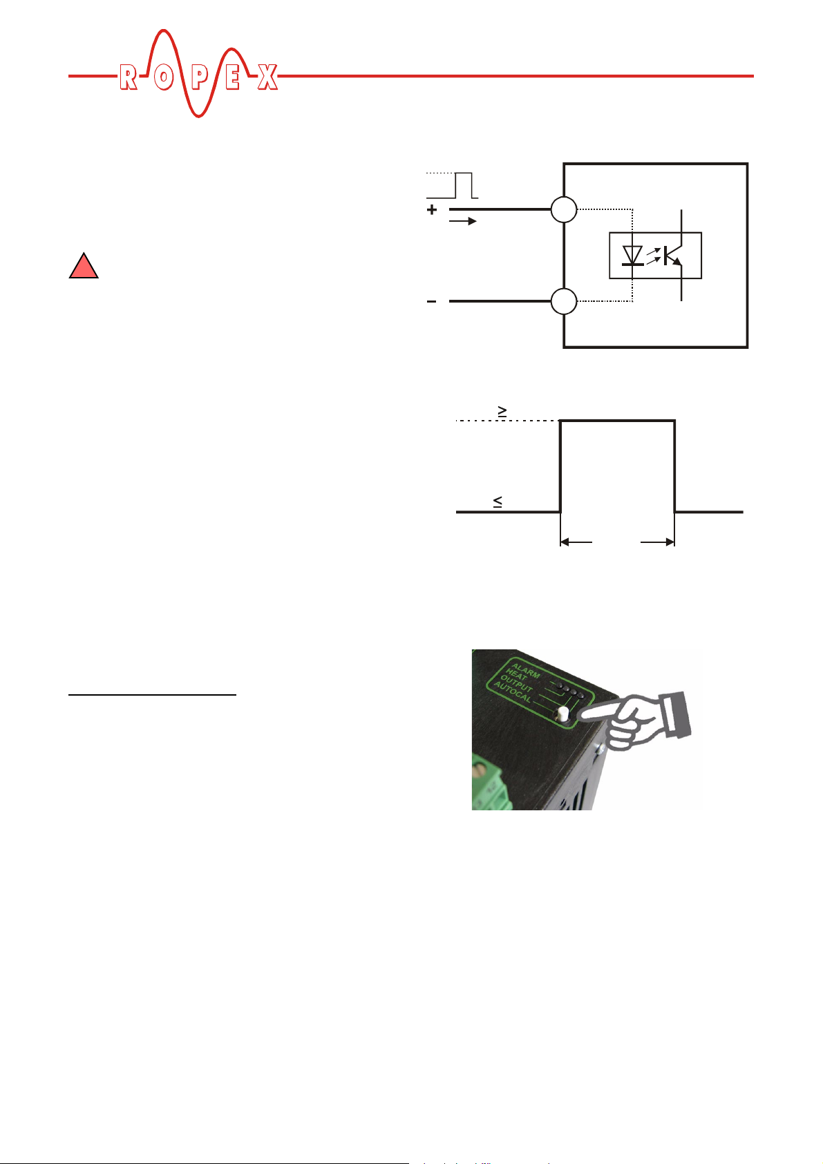
9.5 "START" signal (HEAT)
• By means of a 24 VDC signal at terminals 12+13
24VDC
START
(HEAT)
max. 6mA
GND
12
RES- 403
13
HIGH: 12VDC
START
(HEAT)
LOW: 2VDC
or
• By means of a control contact at terminals 15+18
max.
5mA
18
START
(HEAT)
with
contact
15
RES- 403
0V
When the "START" signal is activated, the controllerinternal set/actual comparison is enabled and the heatsealing band is heated up to the SET temperature. It
remains at this temperature until the signal is deactivated.
The "HEAT" LED on the front panel of the RES-403 is
lit continuously for the duration of the heating phase.
The "START" signal can be activated in two ways:
RES-403 Page 27
The "START" signal is disabled as long as the
!
AUTOCAL function is executing
("AUTOCAL" LED lit, "HEAT" LED blinks).
The terminals 15+18 are not potenial-free and
!
might have the potential of the secondary
voltage of the impulse transformer. For the terminals of the control contact touch voltage protection
must be installed. External grounding is not
allowed. If this warning is ignored, the controller
will be damaged by frame currents.
The set point that is selected for the heatsealing temperature must be greater than 40 °C. If not, the heatsealing band will not be heated up ("HEAT" LED
blinks).
Page 28

Controller functions
The alarm output is switched if the "START" signal is
activated while an alarm signal is indicating error codes
104…106, 111…114, 211, 302 or 303 (up to September 2005: error codes 8…12) (ª section 9.12
"Error messages" on page 31). The heatsealing band is
no longer heated up.
9.6 Measuring impulse duration (as of October 2005)
The length of the measuring impulses generated by the
controller can be set with the parameter. It may be
necessary to set a measuring impulse that is longer
than the default 1.7 ms for certain applications
(ª ROPEX Application Report).
This parameter can only be set by means of
!
the ROPEX visualization software
(ª section 9.10 "Diagnostic interface/visualization
software (as of October 2005)" on page 30).
9.7 Automatic phase angle compensation (AUTOCOMP) (as of October 2005)
If the interval between the two "AUTOCAL" functions is
longer than 2.0 s, "AUTOCAL" is executed normally
again the second time.
AUTOCAL
signal
24VDC
0
Function
AUTOCAL
0
"AUTOCAL"
LED
lit
off
"HEAT"
LED
lit
<2.0s
t
AUTOCOMP
t
t
It may be necessary to compensate the phase angle
displacement between the U
signals for special heatsealing applications (ª ROPEX
Application Report). The "AUTOCOMP" function is
provided for this purpose. It is executed whenever the
"AUTOCAL" function (ª section 9.12 "Error
messages" on page 31) is run twice in quick
succession. The interval between the end of the first
"AUTOCAL" function and the start of the second
"AUTOCAL" must be shorter than 2.0 s. The second
"AUTOCAL" function only takes around 2.0 s and
incorporates the "AUTOCOMP" function.
and IR measuring
R
off
The "HEAT" LED blinks repeatedly when the "AUTOCOMP" function is executed and the actual value
output (terminals 17+14) is set to 0…3°C (i.e. app.
0 VDC).
The "AUTOCOMP" function must be
!
activated in the ROPEX visualization
software (ª section 9.10 "Diagnostic interface/
visualization software (as of October 2005)" on
page 30) (default setting: AUTOCOMP off).
t
Page 28 RES-403
Page 29

Controller functions
9.8 Temperature diagnosis (as of October 2005)
An additional temperature diagnosis can be activated in
the ROPEX visualization software (ª section 9.10
"Diagnostic interface/visualization software (as of
October 2005)" on page 30). The RES-403 checks
whether the ACTUAL temperature is within a settable
tolerance band ("OK" window) on either side of the SET
temperature. The lower ( ) and upper
∆ϑ
( ) tolerance band limits are configured in the
upper
factory to -10 K and +10 K. These values can be set
independently of one another in the ROPEX visualization software.
If the actual temperature is inside the specified tolerance band when the "START" signal is activated, the
temperature diagnosis is activated as well. If the
ACTUAL temperature leaves the tolerance band, the
corresponding error code (307 or 308) is indicated and
the alarm relay is switched (ª section 9.12 "Error messages" on page 31).
Set+∆ϑ
Set+∆ϑ
upper
Set
lower
∆ϑ
lower
Actual value
tolerance band limit is exceeded, the temperature diagnosis is not activated until the parameterized delay
time has elapsed. The temperature diagnosis function
can thus be explicitly deactivated, e.g. if the temperature drops temporarily owing to the closure of the
sealing jaws.
The values that can be set in the ROPEX
!
visualization software for the upper and
lower tolerance band and the delay time are identical to those for the "Temperature OK" signal
(MOD 46).
9.9 Heatup timeout
(as of October 2005)
An additional heatup timeout can be activated in the
ROPEX visualization software (ª section 9.10 "Diagnostic interface/visualization software (as of October
2005)" on page 30).
This timeout starts when the START signal is activated.
The RES-403 then monitors the time required for the
ACTUAL temperature to reach 95% of the SET temperature. If this time is longer than the parameterized
time, the corresponding error code (304) is indicated
and the alarm relay is switched (ª section 9.12 "Error
messages" on page 31).
Time
Alarm
307
If the temperature diagnosis is not activated by the time
the "START" signal is deactivated (i.e. if the ACTUAL
temperature does not exceed the upper or lower
tolerance band limit), the corresponding error code
(309, 310) is indicated and the alarm relay is switched.
An additional delay time (0…9.9s) can be set in the
ROPEX visualization software. The first time the lower
Actual value
Set
95% of Set
Timeout
Time
Heatup time Alarm
304
RES-403 Page 29
Page 30

Controller functions
9.10 Diagnostic interface/visualization software (as of October 2005)
An interface with a 6-pole Western socket is provided
for systemdiagnostics and process visualization. This
interface allows a data connection to be set up to the
ROPEX visualization software using the ROPEX communication interface CI-USB-1.
DIAG
0
1
9
2
8
3
7
4
6
5
Only a ROPEX comunication interface is
!
allowed to be connected to the diagnostic
interface. Connecting another device (e.g. a
telephone cable) could result in malfunctions or
damage to the controller.
2. Blinks slowly (1 Hz)
The system configuration is incorrect and the zero
calibration (AUTOCAL function) was unsuccessful
(ª section 8.11 "Controller configuration" on
page 18). It corresponds to error codes 110…114
(up to September 2005: error codes 10…12).
3. Lit continuously:
This indicates that a fault is preventing the controller
from being started (error codes 101…103, 107, 108,
201…203, 307, 308, 801, 9xx; up to September
2005: error codes 1…7).
As a rule, it refers to an external wiring fault.
B.) Alarm relay (relay contact terminals 5+6):
This contact is set in the factory as follows:
• OPEN in operating states A.1) and A.2), but closed
if a "START" signal is activated in one of these
states.
• CLOSED in operating state A.3)
If the alarm relay is configured opposite to the factory
setting (ª section 8.11.3 "Configuration of the alarm
relay" on page 20), these states are reversed.
The ROPEX visualization software is described in a
separate document.
9.11 System monitoring/alarm output
To increase operating safety and to avoid faulty heatsealing, this controller incorporates special hardware
and software features that facilitate selective fault
detection and diagnosis. Both the external wiring and
the internal system are monitored.
These features assist the operator in identifying the
cause of abnormal operations.
A system fault is reported or differentiated by means of
the following indications.
A.) Red "ALARM" LED on the controller
three states:
1. Blinks fast (4Hz)
The AUTOCAL function should be executed (error
codes 104…106, 211, 302, 303; up to September
2005: error codes 8+9).
C.) Error code output via the 0…10 VDC analog
output (terminals 14+15):
Since a temperature indication is no longer necessary
if a fault occurs, the analog output is used to display
error messages in the event of an alarm.
13 voltage levels (up to September 2005: 12 voltage
levels) are offered for this purpose in the 0…10VDC
range, each of which is assigned an error code
(ª section 9.12 "Error messages" on page 31).
If a state that requires AUTOCAL occurs – or if the controller configuration is not correct – (error codes
104…106, 111…114, 211, 302, 303; up to September
2005: error codes 8…12), the signal at the analog
output jumps back and forth at 1Hz between the
voltage value which corresponds to this error and the
end of the scale (10 VDC, i.e. 300°C or 500°C). If the
"START" signal is activated in one of these states, the
voltage value does not change any more.
Selective fault detection and indication can thus be
implemented simply and inexpensively using the
analog input of a PLC with a corresponding error message (ª section 9.12 "Error messages" on page 31).
Page 30 RES-403
Page 31

Controller functions
An alarm can only be reset by switching the
!
controller off and then on again.
Invalid alarm signals may appear when the
!
controller is switched off owing to the undefined operating state. This must be taken into
account when they are evaluated by the higherlevel controller (e.g. a PLC) in order to avoid false
alarms.
9.12 Error messages
The table below shows how the analog voltage values
correspond with the faults that have occurred. It also
describes the fault and the required corrective action.
The error messages are listed in two separate tables for
controllers "up to September 2005" and "as of October
2005". The block diagram in section 9.13 "Fault areas
and causes" on page 36 permits each fault to be
cleared quickly and efficiently.
13 voltage levels for fault diagnostics appear at the
actual value output of all controllers manufactured as of
October 2005. The error messages are differentiated
even more finely in the controller. The error codes
described below can be displayed with the ROPEX
visualization software (ª section 9.10 "Diagnostic
interface/visualization software (as of October 2005)"
on page 30) to facilitate troubleshooting.
If the actual value output is evaluated in order
!
to identify an error message - in the higherlevel controller, for instance - the tolerance window
must be adjusted to prevent it from being incorrectly interpreted. Please note the tolerances of the
actual value output (ªªªª section 6 "Technical data"
on page 9).
RES-403 Page 31
Page 32

Action if machine
already operating,
HS band not chang.
c
Fault area
Fault area e
Fault area dk
Fault area fgh
Controller functions
Check
(loose contact)
Check power supply
Run RESET
Replace controller
Replace controller
Replace controller
Replace controller
Replace controller
plug-in jumper
Action
STATUS
for first time
if machine started
Cause
(factory set.)
of alarm relay
c
Fault area
signal missing
R
I
e
Fault area
signal missing
R
U
d
Fault area
signals missing
R
and I
R
U
fgh
Fault area
Temperature step, down
(loose contact)
Temperature step, up
Temperature too low/high
Replace controller
Int. faut, contr. defective
Check
plug-in jumper
output wrong
Plug-in jumper for alarm
Check
power supply
(ª section 9.8)
Frequency fluctuation,
inadmissible line frequency
Closed
Run RESET
Replace controller
Replace controller
Replace controller
Replace controller
(ª section 9.9)
Heatup time too long
Triac defective
Int. faut, contr. defective
Int. faut, contr. defective
Int. faut, contr. defective
LED
Error messages as of October 2005
Part 1 of 3:
Page 32 RES-403
ALARM
Tem p .
Temp.
Act. value
Error
500°C
300°C
output;
[°C]
[°C]
Voltage [V]
code
33
20
0.66
(101)
1
66
40
1.33
(102)
2
100
60
2.00
(103)
3
(107)
(108)
133
80
2.66
(307)
4
(308)
(309)
Lit
uously
contin-
(310)
(201)
166
100
3.33
(202)
5
(203)
200
120
4.00
(304)
6
(901)
(913)
(914)
233
140
4.66
(915)
7
(916)
(917)
(918)
Page 33

Controller functions
Action if machine
already operating,
HS band not chang.
fgh
Fault area
---
(loose contact)
Action
STATUS
if machine started
Cause
of alarm relay
ij
for first time
signals incorrect,
R
I
impulse-transformer
incorrect specification of
(factory set.)
of transformer,
Check specification
Fault area
signals
R
incorrect,
and/or I
R
impulse-transformer
incorrect specification of
U
Open
Warning:
impulse-transformer
Temperature too low,
(voltage value
AUTOCAL wasn’t per-
at actual
value output
incorrect specification of
Fault:
Closed
Run AUTOCAL,
signals incorrect,
R
U
Run AUTOCAL
formed, loose contact,
fgh
and/or
(loose contact)
fault area
temperature too high,
formed, loose contact,
ambient temp. fluctuates
then no longer
AUTOCAL wasn’t per-
changes)
Run AUTOCAL
Data error
ambient temp. fluctuates
LED
ALARM
[°C]
Tem p .
500°C
[°C]
Tem p .
300°C
alarm LED blinks; alarm relay is open). When the "START" signal is activated, the warning changes to a fault
output;
Volt. [V]
Act. value
(actual value output no longer jumps back and forth, see bold italic values; alarm LED lit continuously; alarm relay is closed.
NOTE: The specified error messages are initially output as warnings (actual value output jumps back and forth between two values;
code
Error
¯266«
ª500®
¯160«
ª300®
¯5.33«
ª 10 ®
(104)
(105)
Part 2 of 3: Error messages as of October 2005
RES-403 Page 33
fast
(4Hz)
Blinks
Warning:
¯300«
ª500®
¯180«
ª300®
¯6.00«
ª 10 ®
(106)
8
Lit
Fault:
¯333«
¯200«
¯6.66«
uously
contin-
ª500®
ª300®
ª 10 ®
(302)
¯366«
¯220«
¯7.33«
ª500®
ª300®
ª 10 ®
(303)
¯400«
¯240«
¯8.00«
ª500®
ª300®
ª 10 ®
(211)
9
Page 34

Controller functions
Action if machine
already operating,
Action
if machine started
Cause
HS band not chang.
for first time
---
j,
Fehlerbereich
signal incorrect,
R
I
Konfiguration prüfen
calibration not possible
---
i,
Fehlerbereich
signal incorrect,
R
U
Konfiguration prüfen
calibration not possible
---
ij,
Fehlerbereich
Konfiguration prüfen
signals incorrect,
R
and I
calibration not possible
R
U
Temperature fluctuates,
Ext. calibration
temperature too high,
calibration not possible
calibration not possible
Ext. calibration
temperature fluctuates
calibration not possible
Part 3 of 3: Error messages as of October 2005
¯366«
¯220«
¯7.33«
(112)
11
ª500®
ª300®
ª 10 ®
Warning:
Open
Warning:
¯400«
¯240«
¯8.00«
STATUS
(factory set.)
of alarm relay
LED
ALARM
[°C]
Temp.
500°C
Tem p .
300°C
alarm LED blinks; alarm relay is open). When the "START" signal is activated, the warning changes to a fault
Act. value
Error
output;
(actual value output no longer jumps back and forth, see bold italic values; alarm LED lit continuously; alarm relay is closed).
NOTE: The specified error messages are initially output as warnings (actual value output jumps back and forth between two values;
[°C]
Volt. [V]
code
¯333«
¯200«
¯6.66«
ª500®
ª300®
ª 10 ®
(111)
10
Blinks
(113)
12
ª500®
ª300®
ª 10 ®
Fault:
Closed
at actual
(voltage value
Lit
Fault:
(1Hz)
slowly
(114)
value output
contin-
¯433«
¯260«
¯8.66«
(115)
changes)
then no longer
uously
ª500®
ª300®
ª 10 ®
(116)
13
Page 34 RES-403
Page 35

Controller functions
c
e
dk
fgh
fgh
---
---
---
---
Fault area
Action if machine
already operating,
HS-band not chang.
c
Action
for first time
Fault area
if machine started
Cause
signal missing
R
I
Fault area
Fault area e Fault area
signal missing
R
U
Fault areas
(loose contact)
Fault areas
d
fgh
(loose contact)
Fault areas
signals missing
R
and I
U
Temperature step
R
Frequency fluctuation,
Run RESET
Check power supply
Run RESET
Check power supply
Internal fault
inadmissible line frequency
Replace controller
Replace controller
Internal fault,
controller defective
signal
R
and/or I
R
U
Fault areas
j,
Run AUTOCAL
Run AUTOCAL
incorrect
Data error
Fault area
signal incorrect,
R
I
i,
Fault area
check configuration
signal incorrect,
R
U
calibration not possible
ij,
Fault areas
signals incorrect,
R
and I
R
U
check configuration
calibration not possible
check configuration
calibration not possible
signal
¯333«
¯200«
¯6.66«
at analog
(voltage value
Blinks
ª500®
ª300®
ª 10 ®
10
until "START"
does not close
ª500®
ª300®
ª 10 ®
output then
¯365«
¯220«
¯7.33«
slowly
11
no longer
ª500®
ª300®
ª 10 ®
(1Hz)
changes)
¯400«
ª500®
¯240«
ª300®
¯8.00«
ª 10 ®
12
133
80
2.66
4
Lit
Closed
Continuously
166
200
100
120
3.33
4.00
5
6
233
140
4.66
7
STATUS
(factory set.)
of alarm relay
LED
ALARM
Error messages up to September 2005
33
66
40
1.33
2
100
60
2.00
3
Tem p .
Tem p .
Act. value
Error
[°C]
500°C
[°C]
300°C
output ;
Voltage [V]
code
20
0.66
1
¯266«
¯160«
¯5.33«
Open,
fast
(4Hz)
Blinks
¯300«
ª500®
¯180«
ª300®
¯6.00«
ª 10 ®
8
9
RES-403 Page 35
Page 36

9.13 Fault areas and causes
1229
5
Controller functions
6
3
Temperature
4
8
1
The table below explains the possible fault causes.
Fault area Explanation Possible causes
Load circuit interrupted after U
pickoff point
- Wire break, heatsealing band break
R
- Contact to heatsealing band defective
UR
IR
controller
HARDWARE
8
7
c
PEX-W2/-W3 current transformer
signal interrupted
Primary circuit interrupted
measuring wires from current transformer interrupted
- I
R
- Wire break, triac in controller defective
- Primary winding of impulse transformer interrupted
d
Secondary circuit interrupted
before U
pickoff point
R
- Wire break
- Secondary winding of impulse transformer interrupted
9
45
I2
8
32
U2
1
7
U
e
f
g
h
i
Page 36 RES-403
signal missing
R
Partial short-circuit (delta R)
Parallel circuit interrupted
Total short-circuit
U
signal incorrect
R
- Measuring wires interrupted
- Heatsealing band partially bypassed by conducting part
(clamp, opposite heatsealing bar etc.)
- Wire break, heatsealing band break
- Contact to heatsealing band defective
- Heatsealing band installed incorrectly, insulation at
heatsealing bar ends missing or incorrectly installed
- Conducting part bypasses heatsealing band completely
- Up to September 2005: DIP switches 1 - 3 configured
incorrectly (U
- As of October 2005: U
from 0.4…120VAC
range)
2
outside permissible range
2
Page 37

Factory settings
Fault area Explanation Possible causes
- Up to September 2005: DIP switches 4 + 5 configured
j
signal incorrect
I
R
incorrectly (I
- As of October 2005: I
from 30…500A
range)
2
outside permissible range
2
Turns through PEX-W2/-W3
current transformer incorrect
- Check number of turns (two or more turns required for
currents < 30 A)
- Hardware fault (replace controller)
k
Internal controller fault
- Plug-in jumper for alarm output not connected or
incorrectly connected
10 Factory settings
The RESISTRON temperature controller RES-403 is
configured in the factory as follows:
DIP switches
F
O
for
secondary voltage
and current I
U
2
2
(up to September
2005)
F
3
2
4
1
O
N
=6…60VAC
U
2
I
=30…100A
2
DIP switches: 2 ON
5
1, 3, 4, 5 OFF
These switches are automatically set by
the AUTORANGE function on all
controllers manufactured as of October
2005.
Rotary coding switch
for
heatsealing band alloy
and
temperature range
Plug-in jumper
for
alarm relay
Automatic phase
angle compensation
(AUTOCOMP)
[X]
Heatsealing band alloy: Alloy A20
Temperature range: 300°C
Maximum temperature: 300°C
SWITCH POS.
0
1
0
1
9
2
8
3
7
4
6
5
4
5
8
300°C
9
Rotary coding switch: "0" position
Cobtact closes by alarm
SWITCH POS.
0
1
0
1
9
2
8
3
7
4
6
5
4
5
8
300°C
9
AUTOCOMP: OFF
RES-403 Page 37
Page 38

Maintenance
Measuring impuse
duration
[X]
„Temp. OK“ signal
(as of October 2005:
With MOD 46 only)
[X]
Temperature
diagnosis
[X]
Heatup timeout
[X]
[X] As of October 2005:
With ROPEX visualization software only.
Measuring impulse length: 1,7ms
Tolerance band: -10 K…+10K
Temperature diagnosis: OFF
Heatup timeout: OFF
11 Maintenance
The controller requires no special maintenance.
Regular inspection and/or tightening of the terminals –
including the terminals for the winding connections on
the impulse transformer – is recommended. Dust deposits on the controller can be removed with dry compressed air.
Page 38 RES-403
Page 39

How to order
12 How to order
Contr. RES - 403 / . . . VAC
Modification MOD . . (optional, if required)
Please indicate the article numbers of the controller and the required modifications
(optional) in all orders,
115: Power supply 115 VAC, Art. No. 740301
230: Power supply 230 VAC, Art. No. 740302
400: Power supply 400 VAC, Art. No. 740303
Scope of supply: Controller includes connector plug-in
parts (without current transformer)
e.g.
01: MOD 01, Art. No. 800001 (Amplifier for low voltage)
26: MOD 26, Art. No. 800026 (Booster connection)
40: MOD 40, Art. No. 800040 ("Temperature OK" signal)
e.g. RES-403/400 VAC + MOD 26
(controller for 400 VAC power supply with booster connection)
Art. No. 740303 + 800026 must be ordered
Current transformer PEX-W3
Art. No. 885105
Line filter LF- . . 480
06: Continuous current 6 A, 480VAC, Art. No. 885500
35: Continuous current 35 A, 480VAC, Art. No. 885506
Impulse transformer
See ROPEX Application Report
for design and ordering information
Communiction interface CI-USB-1
Art. No. 885650
Potentiometer PD- .
3: For 300°C range, Art. No. 881103
5: For 500°C range, Art. No. 881105
Scope of supply: Potentiometer with digital dial
Temp. meter ATR- .
3: 300°C range, Art. No. 882130
5: 500°C range, Art. No. 882150
RES-403 Page 39
Page 40

Booster B- . . . 400
For more accessories: ª"Accessories" leaflet
How to order
075: Max. pulse load 75A, 400VAC, Art. No. 885301
100: Max. pulse load 100 A, 400VAC, Art. No. 885304
Page 40 RES-403
Page 41

Index
13 Index
A
Accessories 6
Actual value output 25
Alarm output 30
Alarm relay 10
Alloy 19
Ambient temperature 10
Analog temperature meter 6
Application 4
Application Report 11
AUTOCAL 6
AUTOCOMP 28
Automatic phase angle compensation 28
Automatic zero calibration 6
AUTOTUNE 6
, 20
, 22
, 14, 18
, 21, 26
, 21, 26
B
Booster 7, 16, 40
Burning in the heatsealing band 20
, 22
C
Circuit breaker 13
CI-USB-1 7
Communication interface 7
Controller configuration 18
Controls 23
Current transformer 14
, 30, 39
, 30, 39
, 39
Impulse transformer 7
Installation 10
Installation procedure 11
Installation regulations 11
, 11
, 13, 39
L
Line filter 7, 13, 14, 39
Line frequency 6
Line voltage 9
, 9
M
Maintenance 38
Measuring impulse duration 28
Modifications 7
MODs 7
, 16, 17, 39
, 16, 17, 39
O
Overheating of heatsealing band 6
P
PEX-W2/-W3 3
PEX-W3 14
Phase angle compensation 28
Potentiometer 6
Power dissipation 10
Power supply 13
Principle of operation 5
, 39
, 24, 39
, 39
D
Degree of protection 10
Diagnostic interface 30
Digital temperature meter 6
Dimensions 11
DIP switches 18
E
Error messages 31
External switching amplifier 7
F
Factory settings 37
Fault areas 36
Fault diagnosis 6
H
HEAT 21, 27
Heatsealing band type 9
Heatup timeout 29
How to order 39
I
Impulse heatsealing method 4
, 16
R
Replacing the heatsealing band 21, 22
S
Secondary current I218
Secondary voltage U
Set point potentiometer 6
Set point selection 9
Signal „Temperatur erreicht“ 8
"START" signal 21
Startup 18
System diagnostics 30
System monitoring 30
2
, 24
, 27
18
, 24
T
TCR 3, 20
Technical data 9
Temperature coefficient 3
Temperature control 4
Temperature diagnosis 29
Temperature indication 25
Temperature indicator 25
Temperature meter 6
Temperature OK signal 17
, 20
, 39
RES-403 Page 41
Page 42

Index
Temperature range 9, 19
Temperature reached signal 8
Temperature setting 24
Transformer 3
Type of construction 9
, 7, 13, 39
, 17
V
View of the controller 18
Visualization software 30
W
Wiring 11, 13
Wiring diagram 15
, 16
Page 42 RES-403
 Loading...