

Page 1

Page 2

Page 3

TM24H4O
TM30H4O
TM36H4O
Page 4
In line with the company’s policy of continual product improvement, the aesthetic and dimensional
characteristics, technical data and accessories of this appliance may be changed without notice.
CONTENTS
Conformity And Range
The Instructions Before Use
Name of Parts
Technical Data
GENERAL
INFORMATION
Outdoor Unit Working Temperature Range
Electrical Connections
Installing The Outdoor Unit
Bleeding
Maintenance
Installation Dimension Diagram
INSTALLER
Check After Installation
GENERAL INFORMATION
1
2
3
4
4
5
7
7
8
8
9
The products in this manual may be different with the rea one, according to different models, l
some models have displayer and some models without displayer, the position and shape of
the displayer please refer to the real one.
This appliance is not intended for use by persons (including children) with reduced physical,
sensory or mental capabilities, or lack of experience and knowledge, unless they have been
given supervision or instruction concerning use of the appliance by a person responsible for
their safety.
Children should be supervised to ensure that they do not play with the appliance.
Page 5
Explanation of Symbols
Indicates a hazardous situation that, if not avoided, will
DANGER
WARNING
CAUTION
N OTIC E
result in death or serious injury.
Indicates a hazardous situation that, if not avoided, could
result in death or serious injury.
Indicates a hazardous situation that, if not avoided, may
result in minor or moderate injury.
Indicates important but not hazard-related information,
used to indicate risk of property damage.
Indicates a hazard that would be assigned a signal word
WARNING or CAUTION.
CONFORMITY AND RANGE
This appliance can be used by children aged from 8 years and above and persons with reduced physical,sensory
or mental capabilities or lack of experience and knowledge if they have been given supervision or instruction
concerning use of the appliance in a safe way and understand the hazards involved.
Children shall not play with the appliance.
Cleaning and user maintenance shall not be made by children without supervision.
Please read this owner's manual carefully before operating the unit and keep it carefully for consultation.
Instructions for installation and use of this product are provided by the manufacturer.
Only use the air conditioner as instructed in this booklet. These instructions are not intended to
cover every possible condition and situation. As with any electrical household appliance, common sense
and caution are therefore always recommended for installation, operation and maintenance.
GENERAL INFORMATION
1
Page 6

THE INSTRUCTIONS BEFORE USE GENERAL INFORMATION
WARNING
When having a burning smell or
★ ★
smoke,please turn off the power
supply and contact with the service center.
If the abnormity still exists,the unit
may be damaged,and may cause
electric shock or fire.
Power must adopts the special
★
circuit to prevent fire.
Otherwise, it can cause electric
shock or fire.
★ ★
Otherwise,the accumulated dusts
may cause overheating or fire.
The power supply must adopt the
special circuit that with air switch
protection and assure it has enough capacity.The unit will be turned
on or off according to your requirement automatically,please do not
turn on or turn off the unit frequently,otherwise disadvantage effect
may be caused to the unit.
Disconnect the power supply if
long putting the air conditioner
out of use.
Never cut off or damage power
★
cables and control wires. If the
power cable and signal control
wire were damaged, change
them by professional.
Never damage the electric wire
or use the electric wire which is
not appointed.
Otherwise,it will cause overheating
or fire.
When cleaning,it is necessary
★ ★
to stop driving and turn off the
power supply.
Cut off power supply
Otherwise,it may cause electric
shock or damage.
Please note whether the insta-
★ ★
lled stand is firm enough or not.
Rated voltage of this air conditioner 208/230V, 60Hz, The compressor will vibrate sharply if the
voltage is too low, resappointed.
amage to refrigerating system.
Electrical component are easy to
damage if the voltage is too high.
Don't step on the top of the
outdoor unit or place something
on it.
Don't attempt to repair the air
★
conditioner by yourself.
The wrong repair will lead to an
electric shock or fire,so you should
contact the service center to repair.
Earthing: The unit must be reli-
★
ably earthed.The earthing cable
shall be connected to the special earthing device in the construction.
If it is damaged, it may lead to the
fall of the unit and cause the injury.
As falling off the outdoor unit can be
dangerous.
2
Page 7

NAME OF PARTS GENERAL INFORMATION
TM24H4O TM30H4O
WARNING
Be sure to cut off the power supply before cleaning the air conditioner; otherwise electric
shock might happen.
Wetting of air conditioner may cause the risk of electric shock. Make sure not to wash
your air conditioner in any case.
Volatile liquids such as thinner or gasoline will cause damage to the appearance of air
conditioner. (Only use soft dry cloth moist cloth clean the air conditioner cabinet).
This product must not be disposed together with the domestic waste.
This product has to be disposed at an authorized place for recycling of electrical and
electronic appliances.
The temperature of refrigerant circuit will be high,please keep the interconnection cable
away from the copper tube.
OUTDOOR UNIT
No. Description
1 Air outlet grille
2 Valve
Note: The above figures are only intended to a simple
diagram of the appliance and may not correspond to the
appearance of the units that have been purchased.
、
TM36H4O
、
1
2
70+2
TM30H4O
TM36H4O
WARNING
If the supply cord is damaged, it must be replaced by the manufacturer or its service agent or a similarly
qualified person in order to avoid a hazard.
Be sure to cut off the power supply before cleaning the air conditioner; otherwise electric shock might happen.
Wetting of air conditioner may cause the risk of electric shock. Make sure not to wash your air conditioner in
any case.
Volatile liquids such as thinner or gasoline will cause damage to the appearance of air conditioner. (Only use
soft dry cloth moist cloth clean the air conditioner cabinet).
Do not dispose this product as unsorted municipal waste. Collection of such waste separately for special
treatment is necessary.
The temperature of refrigerant circuit will be high, please keep the interconnection cable away from the copper
tube.
1
OUTDOOR UNIT
No. Description
1 Air outlet grille
2 Valve
Note: The above figures are only intended to be a simple
diagram of the appliance and may not correspond to
the appearance of the units that have been purchased.
3
2
Page 8

TECHNICAL DATA GENERAL INFORMATION
MODE
Electrical data
Electricity supply
Fuse or air switch
Minimum power cord section
Size and clearance
L
P
L
P
H
H
TM24H4O
208/230V,60HZ
35
3.3
920
380
790
A
mm
mm
mm
mm
TECHNICAL DATA GENERAL INFORMATION
MODE
Electrical data
Electricity supply
Fuse or air switch
Minimum power cord section
Size and clearance
L
P
L
P
H
H
TM30H4O
208/230V,60HZ
30
3.3
920
370
787
A
mm
mm
mm
mm
2
2
TECHNICAL DATA GENERAL INFORMATION
MODE
Electrical data
Electricity supply
Fuse or air switch
Minimum power cord section
Size and clearance
L
P
L
P
H
H
TM36H4O
208/230V,60HZ
35
3.3
1016
362
1103
A
mm
mm
mm
mm
OUTDOOR UNIT WORKING TEMPERATURE RANGE GENERAL INFORMATION
Maximum cooling
Maximum heating
Outdoor side DB/WB(°F
118.4(48)/-
80.6(27)/-
/℃)
2
4
Page 9

ELECTRICAL CONNECTIONS INSTALLER
TM24H4O
TM30H4O
TM36H4O
1. Remove the handle at the right side plate of the outdoor
unit (one screw).
3. Fix power connection wire by wire clamp.
4. Ensure wire has been fixed well.
5. Install the handle.
An all-pole disconnection switch having a contact
separation of at least 3mm in all pole should be
connected in fixed wiring.
The connection pipes and the connectiong wirings
of the unit A and unit B must be corresponding to
each other respective.
Note: the above figures are only intended to be a simple
diagram of the appliance and may not correspond to the
appearance of the units that have been purchased.
TM24H4O
2. Remove the cable clamp, connect the power con
-nection cable with the terminal at the row of conn
-ection and fix the connection. The fitting line distr
-ibuting must be consistent with the indoor unit.
terminal of line bank.
Wiring should meet that of indoor unit.
Wrong wire connection may cause malfunction of
some electric components.After fixing cable, ensure
that leads between connection to fixed point have
some space.
The appliance shall be installed in accordance with
national wiring regulations.
L1
yellowgreen
L2L1
L2
POWER
L1 L2
Power cord
N(1)
2
white
(blue)
black
red
(brown)
INDOOR UNIT A
To unit A
3
green
yellow-
( )
green
connecting
cable
To unit B
connecting
cable
N(1)
2
white
(blue)
black
red
(brown)
INDOOR UNIT B
To unit C
connecting
cable
To the power supply
3
green
yellow-
( )
green
white
(blue)
N(1)
2
3
green
red
black
(brown)
yellow-
( )
green
INDOOR UNIT C
5
Page 10

ELECTRICAL CONNECTIONS INSTALLER
X
T
N
(
1
)
(
1
)
X
T
N
(
X
X
T
1
2
X
T
N
(
1
)
P
O
W
E
R
L
1
L
L
1
2
2
3
2
N
(
1
3
1
)
2
(
1
)
2
N
(
1
)
2
3
TM30H4O
OUTDO OR UNIT
4
)
1
P
E
INDO OR UN IT D
3
P
E
2
L
2
3
E
P
2
)
INDO OR UN IT A
2
T
E
P
(
N
INDOO R UNIT B
3
3
3
N
E
P
3
N
INDO OR UN IT C
TM36H4O
X
L
1
L
1
P
O
T
L
2
2
L
E
R
W
1
T
X
3
)
1
(
N
2
E
P
3
2
(
N
)
1
INDOOR UNIT A
2
T
X
2
N
)
1
(
E
P
2
N
)
1
(
INDOOR UNIT B
OU TDOOR UNIT
3
E
P
3
INDOOR UNIT C
5
T
3
3
X
1
(
N
)
2
E
P
1
(
N
)
2
INDOOR UNIT E
3
E
P
3
4
X
3
T
1
(
N
)
2
E
P
1
(
N
)
2
INDOOR UNIT D
X
3
T
N
)
1
(
2
3
2
(
1
N
)
6
Page 11

INSTALLING THE OUTDOOR UNIT INSTALLER
Location
Use bolts to secure the unit to a flat, solid floor.
When mounting the unit on a wall or the roof, make
sure the support is firmly secured so that it cannot
move in the event of intense vibrations or a strong
wind.
Do not install the outdoor unit in pits or air vents
●
Installing the pipes
Use suitable connecting pipes and equipment for
the refrigerant R410A.
Models(m) 18Kx2 28Kx4
Max. connection pipe length
Max. connection pipe length
(Simple one indoor unit)
24Kx2 24Kx3
20 70
201060
10
20
20
Caution: Installation Must be Performed in
Accordance with the NEC/CEC by Authorized
Personnel Only.
Install the drain fitting and the drain hose
(for model with heat pump only)
Condensation is produced and flows from the outdoor unit when the appliance is operating in the
heating mode. In order not to disturb neighbours
and to respect the environment,install a drain fitting
and a drain hose to channel the condensate water.
Install the drain fitting and rubber washer on the
outdoor unit chassis and connect a drain hose to it
as shown in the figure.
Models(m) 30Kx4
Max. connection pipe length
Max. connection pipe length
(Simple one indoor unit)
36Kx5 42Kx5
70
25
752575
25
The refrigerant pipes must not exceed the maximum
heights 10m(18Kx2&24Kx2&24Kx3&28Kx4&30KX4
&36KX5&42KX5).
Wrap all the refrigerant pipes and joints.
Tighten the connections using two wrenches working in opposite directions.
BLEEDING INSTALLER
Humid air left inside the refrigerant circuit can cause compressor malfunction. After having connected the indoor
and outdoor units, bleed the air and humidity from the
refrigerant circuit using a vacuum pump.
(1) Unscrew and remove the caps from the 2-way and 3 way valves.
(2) Unscrew and remove the cap from the service valve.
(3) Connect the vacuum pump hose to the service valve.
(4) Operate the vacuum pump for 10-15 minutes until an
absolute vacuum of 10 mm Hg has been reached.
(5) With the vacuum pump still in operation, close the
low-pressure knob on the vacuum pump coupling.
Stop the vacuum pump.
(6) Open the 2-way valve by 1/4 turn and then close it
after 10 seconds. Check all the joints for leaks using
liquid soap or an electronic leak device.
(7) Turn the body of the 2-way and 3-way valves. Discon nect the vacuum pump hose.
(8) Replace and tighten all the caps on the valves.
Vacuum pump Vacuum pump
Diameter (mm)
Φ9.52
Φ16
Φ12
Φ19
Twisting moment (N.m)
15-20Φ6
35-40
60-65
45-50
70-75
30 36 42K unit need to be installed the indoor unit
conversion joint
Vacuum pump
(2)Turn
(8) Secure
2-way valve
(6) Open by 1/4 turn
(7)Turn to open fully
alve cap
V
(2)Turn
(8) Secure
Connect to the
indoor unit
Service
inlet
(2)Turn
(8) Secure
INDOOR
Refrigerant fluid di
UNIT
3-way valve
(7)Turn to open fully
Valve cap
rection of fiow
6
Page 12

MAINTENANCE INSTALLER
Use suitable instruments for the refrigerant R410A.
Do not use any other refrigerant than R410A.
●
Do not use mineral oils to clean the unit.
INSTALLATION DIMENSION DIAGRAM INSTALLER
The installation must be done by trained and qualified service personnel with reliability according to this
manual.
Contact service center before installation to avoid the malfunction due to unprofessional installation.
When picking up and moving the units, you must be guidedby trained and qualified person.
Ensure that the recommende dspace is left around the appliance.
TM24H4O
TM30H4O
TM36H4O
or above
30c m
Space to the cover
or above
200 cm
(Air outlet side)
50c
Space to the cover
50c
m
or more
Space to the cover
m
or more
30cm
(Air inlet side)
50c m
Space to the wall
or above
or above
or above
30c m
Space to the cover
or above
200 cm
(Air outlet side)
30c m
or a bove
(Air inlet side)
50c m
Spa ce t o the w all
or a bove
7
Page 13

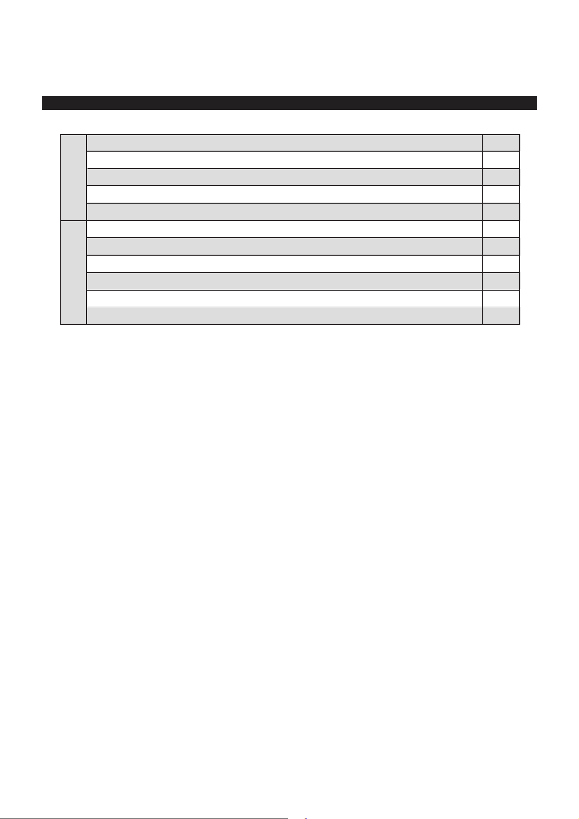
CHECK AFTER INSTALLATION INSTALLER
Check Items
Is the installation reliable?
Has the gas leakage been checked?
Is the thermal insulation of the unit
sufficient?
Is the drainage smooth?
Does the power supply voltage accord
with the rated voltage specified on the
nameplate?
Are the lines and pipelines correctly
installed?
Has the unit been safely grounded?
Problems Owing to Improper Installation
The unit may drop, vibrate or make noises
May cause unsatisfactory cooling (heating)
effect
May cause condensation and water dropping
May cause condensation and water dropping
The unit may bread down or the components
may be burned out
The unit may bread down or the components
may be burned out
Risk of electrical leakage
Are the models of lines in conformity
with requirements?
Are there any obstacles near the air
inlet and outlet of the indoor and outdoor units?
Have the length of refrigerating pipe
and refrigerant charge amount been
recorded?
The unit may bread down or the components
may be burned out
The unit may bread down or the components
may be burned out
It is not easy to decide the charge amount
of refrigerant.
8
Page 14

Page 15

Page 16

66129924603
 Loading...