

Page 1

ATTENTION
For the Rail Set with OT Splice, this task should be performed by no fewer than two people.
For the Rail Set with OT Splice, make sure the Joint part is adequately supported during the
mountin
g p
rocess.
Disassembly method of the Bracket
①
Loosen the Bracket screw and
rotate the Fastener to remove the
bracket.
Cleaning
Be aware that direct contact with water, wiping the product with paint thinner or other
solvent, or cleaning it with chemicals could cause malfunction, discoloration or distortion.
If the product becomes dirty, clean it by wiping with a clean, soft dry cloth.
Disposal of packing materials
Do not leave packing materials at the installation site.
Separate combustible cardboard from noncombustible waste.
Observe the local waste separation regulations when disposing of the materials.
Motorized Curtain Tracks
PROGRESS 50 Rail Set
Thank you for purchasing TOSO products. To ensure safe use of this
product, please read the following thoroughly and keep this manual
stored.
Guide for Distributors and Installation Contractors
This manual contains information for a user to safely operate this product.
Please provide this manual to a customer.
INDEX
Caution
Product view and part names
Cleaning
Disposal of Packing Materials
Installation and DisassemblyMethod
Instruction Manual
Page 2
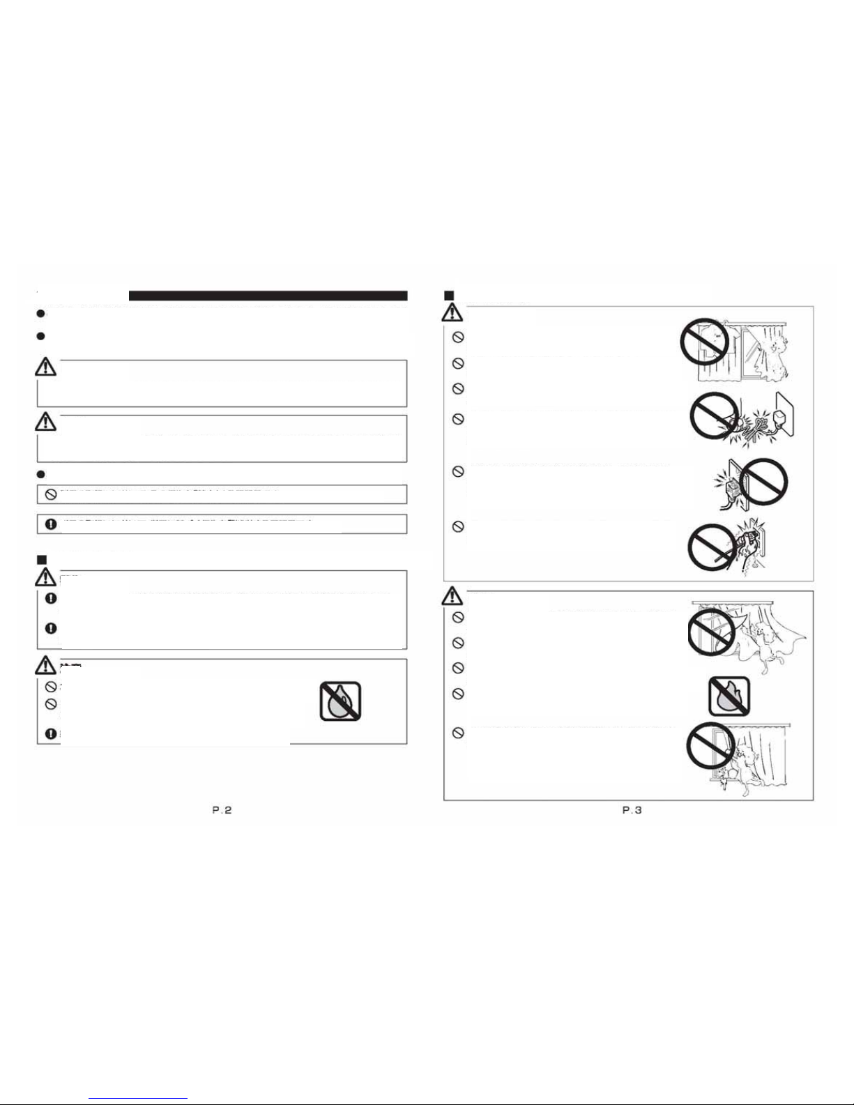
CAUTION
This manual contains cautions and instructions for safe use of the product.
Please read it carefully before use and ensure appropriate use.
This document illustrates the dangers of using this product without taking necessary
precautions. Please refer to below symbols for different types of safety points.
CAUTION
CAUTION
CAUTION
ATTENTION
ATTENTION
ATTENTION
Illustrates when misused, there are dangers of serious injuries or possible
fatal accidents.
Illustrates when misused, there are dangers of casualties or possible
phy
sical damage of the product.
This document illustrates safety points to be kept using below symbols.
Illustrates specific conducts which are prohibited.
Illustrates specific guidelines which are enforced.
Precautions upon installing the product (Please read before installation.)
Check the foundation base and strength of the material before installing this
product. If not installed properly to the foundation base, there are dangers of it
falling.
Install a product as instructed with necessary quantity of brackets. If not
the product may fall.
This product is intended for indoor use. Please do not use it
for exterior purpose.
Locations subject to high temperatures and high humidity,
or areas where water may leak, should be avoided.
Make sure to install a product horizontally.
Safety in Use (Please read thoroughly)
Do not hang anything on this product or do
not hang down. This may cause
accident.
Power source for this product is AC100V〜240V.
Do not use any other power supply.
This product supports our designated switch only.
Do not use any other switch.
Avoid any actions that may damage the power
cord or plug. Using damaged components may
result in electric shock, short circuits, or fire.
Clean power plugs at regular intervals. Plugs
exposed to moisture or to excessive dust may lead
to insulation failures or cause fires.
Avoid handling power plugs with wet hands.
Doing so may result in electric shock.
When there is strong wind, please either close the
window or have the curtain completely open.
Please do not dismantle the mechanical assembly nor
lubricate the moving parts of this product. This will ensure
physical damage or malfunction of the product.
To avoid breakage and malfunction, do not disassemble
this product.
Please do not use it by open flames.
Around the area where the screen is to open and
close, please remember to clear all objects which
may break when placed around the screen.
Page 3
ATTENTION
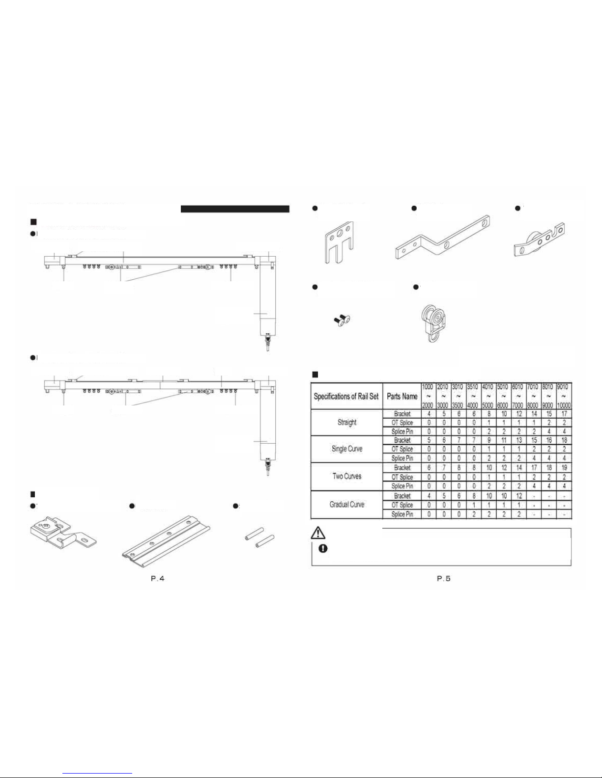
Product view and parts names
Product view and parts names
Rail Set (Without OT Splice )
End side Pulley
Stop
Ceiling Single Bracket M2
Pilot Roller
Pilot Roller
Track
Motor side Pulley
Motor side Pulley
Noiseless Roller
Noiseless Roller
End side Pulley
Stop
Ceiling Single Bracket M2 OT Splice
Motor Set
(sold separately)
Motor Set
(sold separately)
Rail Set (With OT Splice )
Attached Parts
Ceiling Single Bracket M2
OT Splice
Splice Pin
Joint Plate
X 1 pc *
Master Roller Arm
X 1 pc *
Pilot Roller Plate
with Wheel
X 1 pc *
Pilot Roller fixation Screw
X 2 pcs *
Noiseless Roller
10 pcs / m *
*For the Rail Set without a Joint,
all parts are fitted to the Rail Set.
The number containing of attached parts
Fixing screws are not supplied for the Bracket. Select the appropriate
screws suitable for the material of the base.
Page 4
ATTENTION
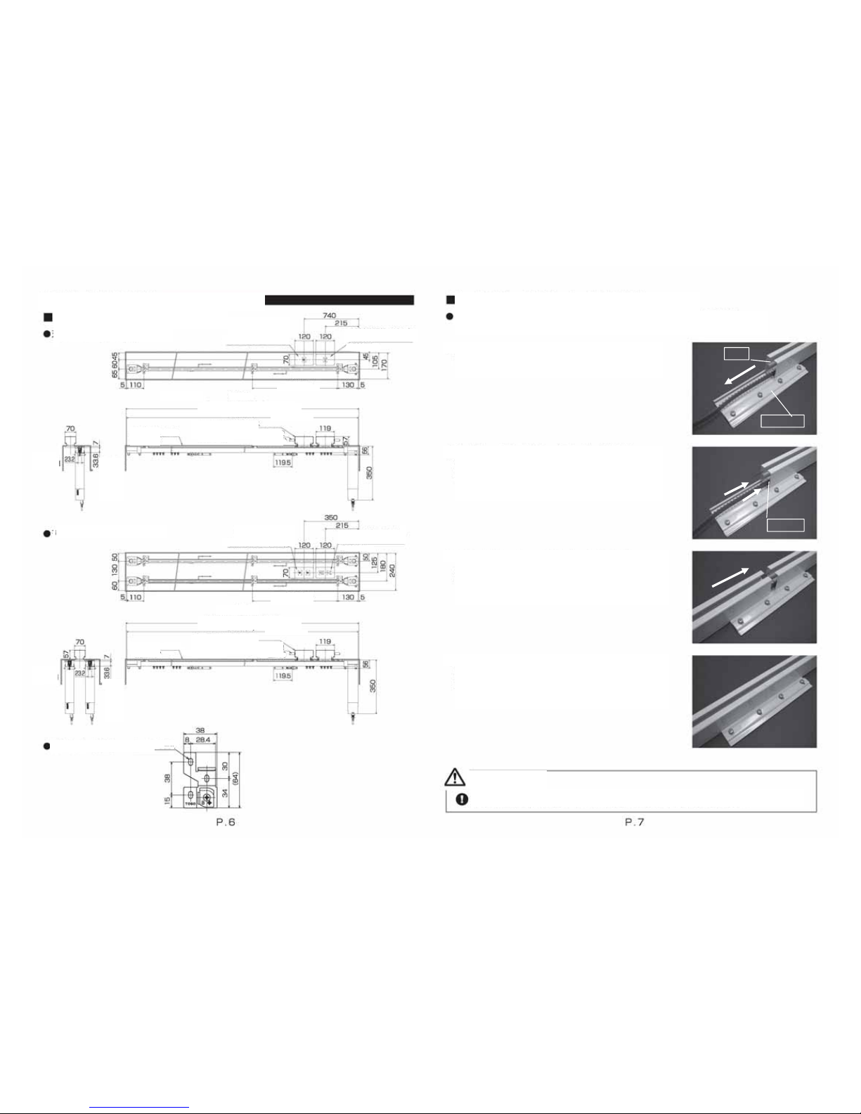
Installation and Disassembly Method
Installation Dimensions & Diagram
Ceiling Single Attachment
Ceiling Double Attachment
<Window side>
For one Modular plate
For two Modular plate
<Window side>
Outlet with the ground
(Separate work)
900 mm or less
<Room side>
<Room side>
900 mm or less
Outlet with the ground
(Separate work)
Window
side
Window
side
Room
side
Room
side
Box width = Product length (L) + 10mm
Box width = Product length (L) + 10mm
Product length (L)
Product length (L)
Switch box for one switch box
(Separate work)
Switch box for one switch box
(Separate work)
Piping, wiring
(Separate work)
Piping, wiring
(
Separate work
)
Curtain box
(Separate work)
Curtain box
(Separate work)
Bracket Dimension
-
How to assemble the Track (with OT Splice).
For the Rail Set with OT Splice, join the Track by the procedure described
below before fitting.
Loosen the OT Splice Screw and insert by sliding
along the Track groove.
Inset the Splice Pin into the opening of a Track.
(If insertion is difficult, tap with a wooden hammer
or similar tool.)
Inset the other Track into the OT Splice.
(If insertion is difficult, cover the Pulley with a cloth
and tap with a wooden hammer or similar tool.)
Position the Track so that the joint section is at the
center of the OT Splice, then tighten the screws of
the OT Splice.
①
②
③
④
Check to confirm that the OT Splice is securely attached to the Track.
Splice Pin
OT Splice
Track
Page 5
ATTENTION
⑤
⑥
②
①
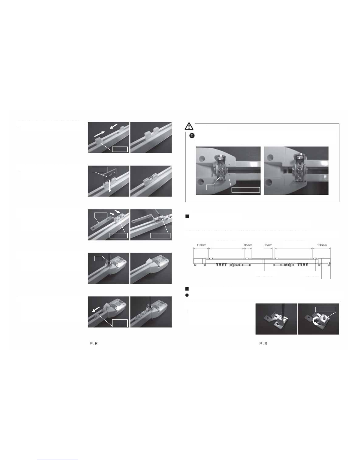
When securing the Stop into position, fit in such a way that the convex portion of
the Stop fits into the concave portion of the Pulley. Align carefully; an improper fit
ma
y
cause the Stop to fall off.
Location of Bracket
Refer to chart below, determine the locations of the Brackets.
For the Rail Set with OT Splice, fit Brackets to both sides of the OT Splice.
Pilot Roller PlateFixation Screw
M R Arm
Joint Plate
Pilot Roller
Fix Master Roller Arm and Pilot
Roller Plate with Wheel with the
Pilot Roller attachment screw.
Use the Joint Plate to join the Pilot
Rollers.
Place the Pilot Rollers end to end.
⑦
○
×
Stop
The concave portion
within 900 mm on
either side
within 900 mm on
either side
Use a screwdriver to loosen the
Stop screw, then remove the Stop.
⑧
Stop
OT Splice Bracket
⑨
①
Insert Noiseless Rollers and secure
the Stop into place.
(Two-way draw, insert the same
number of Noiseless Rollers from
the Pulley at both ends.)
Installation method of the bracket
After attaching the Brackets to the product body, fit the Brackets to the mounting surface.
Loosen the Bracket screw and
rotate the Fastener.
Noiseless
Roller
The fastener
Page 6
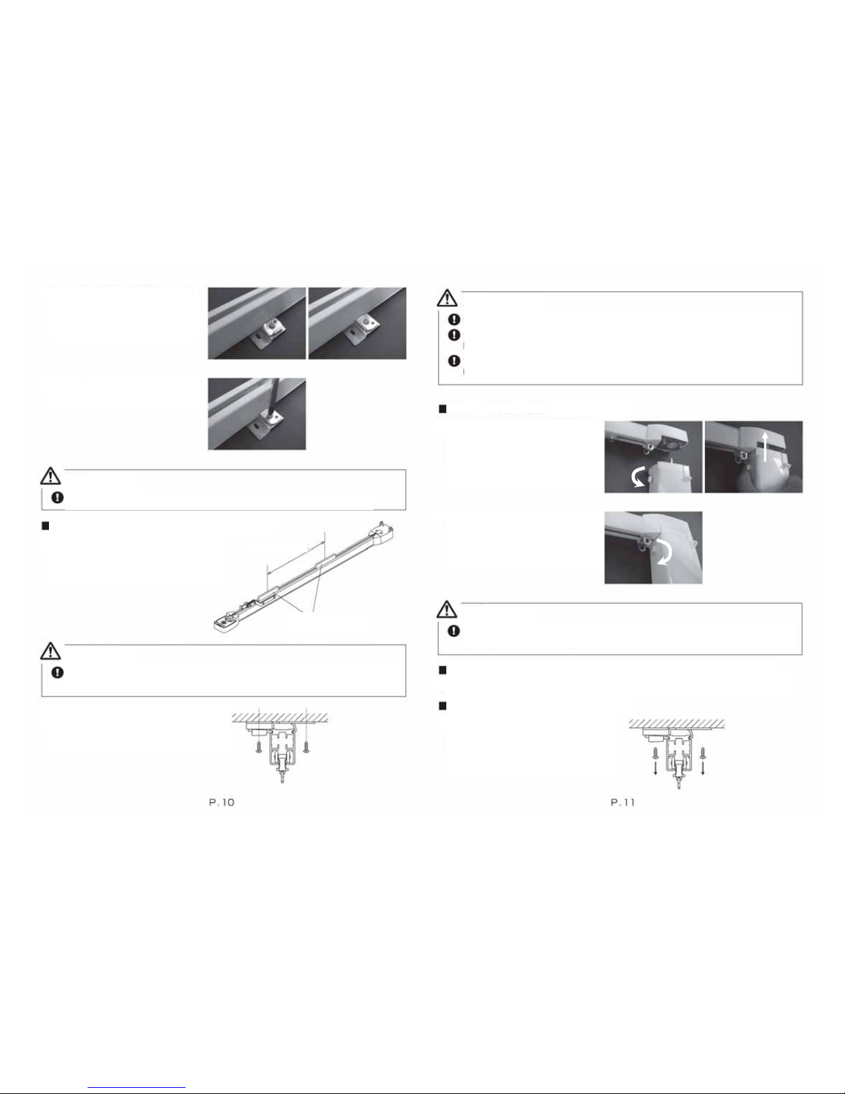
Insert by sliding along the Track
groove, Nip the groove of the
Track with the Fastener.
②
Be sure to use four fixing screws or more for each bracket. Using too few screws
may cause the Product to fall off at some point.
For the Rail Set with OT Splice, make sure the Joint part is adequately supported
during the mounting process. The Product may fall off .
For the Rail Set with OT Splice, this task should be performed by no fewer than two people.
ATTENTION
Tighten the screw to ensure firm
attachment.
③
Installation method of the Moto
r
Loosen the Motor mounting screws,
then insert the Motor into the Motor
side Pulley while keeping the Motor
mounting screws in place.
①
ATTENTION
Check to confirm that the Brackets are securely attached to the Track.
Insert cardboard pads in the Rail groove
at 1m intervals.
(Use the cardboard pads used for
packaging.)
Installation method of the product body
①
Tighten the Motor mounting screw,
and fix the Motor surely.
②
Within 1m in equality
ATTENTION
①
Check to confirm that the Motor is securely attached to the Track. (Pull down on
the Motor to confirm that it is securely mounted.)
Disassembly method of the Motor
While supporting the Track, remove
the mounting screws for the Bracket
and remove the Rail set.
Disassembly method of the Rail Set
Loosen the Motor mounting screws, and remove the Motor while pulling to keep the
mounting screws clear.
①
cardboard pads
ATTENTION
To keep the Belt from coming off, lift the Track only after inserting the
cardboard
p
ads.
Lift the Track and mount the product with
the mounting screws.
②
 Loading...