

TOSO Mytec 01 Loop Double Type, Mytec 01 Loop Link Type, Mytec 01 Loop Link Double Type Instruction Manual
Page 1
No. R−120021E
Instruction Manual
Double Type/Link Type/Link Double Type
INDEX
RollerBlind
Mytec 01 Loop
Thank you for purchasing TOSO products. To ensure safe use of this product,
please read the following thoroughly and keep this manual stored.
Guide for Distributors and Installation Contractors
This manual contains information for a user to safely operate this product.
Please provide this manual to a customer.
First edition
■ Caution ・・・・・・・・・・・・・・・・・・・・・・・・・・・・・・・・・・・・・・・・・・・・・ 2
■ Product View and Part Names・・・・・・・・・・・・・・・・・・・・・・・・・・・・・・ 4
■ Installation Type ・・・・・・・・・・・・・・・・・・・・・・・・・・・・・・・・・・・・・・・ 6
■ Installation and Detachment of a Double Type・・・・・・・・・・・・・・・・・・・ 6
■ Installation and Detachment of a Link Type・・・・・・・・・・・・・・・・・・・・・ 8
■ Installation and Detachment of a Link Double Type・・・・・・・・・・・・・・・11
■ How to Operate・・・・・・・・・・・・・・・・・・・・・・・・・・・・・・・・・・・・・・・・15
■ How to Adjust the Screen Operation Force and the Ascent S peed ・・・・・・16
■ Fixing Improper Rolled up Scree n ・・・・・・・・・・・・・・・・・・・・・・・・・18
■ Troubleshooting・・・・・・・・・・・・・・・・・・・・・・・・・・・・・・・・・・・・19
■ Cleaning・・・・・・・・・・・・・・・・・・・・・・・・・・・・・・・・・・・・・・・・・・・・19
Page 2
Caution
* This manual contains cautions and instructions for safe use of the product.
Please read it carefully before using to ensure appropriate use.
●
This document illustrates the dangers of using this product without taking necessary
precautions. Please refer to the symbols below for different types of safety points.
●
This document illustrates safety points to be followed using the symbols below.
Illustrates specific actions which are prohibited.
Illustrates specific guidelines which must be followed.
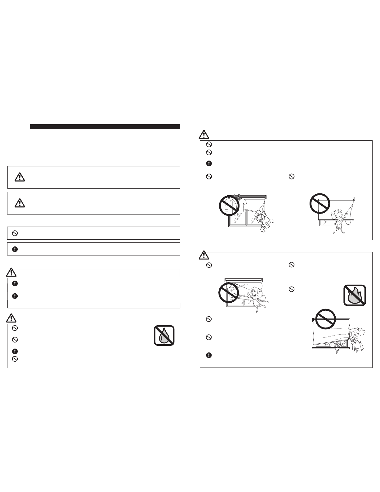
Caution
■ Precautions upon installing the product (Please read before installation.)
Check the foundation base and strength of the material before installing this product.
If not installed properly to the foundation base, there are dangers of it falling.
Install this product as instructed with the necessary quantity of brackets. Otherwise
the product may fall.
Warning
Warning
Caution
Illustrates that if this product is misused, there are dangers of
serious injuries or possible fatal accidents.
Illustrates that if this product is misused, there are dangers of
casualties or possible physical damage of the product.
P. 2
This product is intended for indoor use. Please do not use it for outdoor
purposes.
Locations subject to high temperatures and high humidity, or areas
where water may leak, should be avoided.
Make sure to install this product horizontally.
Do not grab the set bar to carry or lift this product. It may cause damage
to the product.
When there is a strong wind, either
close the window or have the Screen
completely rolled up.
Please do not dismantle the mechanical
assembly nor lubricate the moving parts
of this product. This will ensure physical
damage or malfunction of the product.
Please do not use it by
open flames.
■ Safety in Use (Please read thoroughly.)
Please do not hang from or pull on
this product. This may damage the
product or cause it to fall down.
Please do not operate the product
abrup tly or with unreasona ble force.
This may cause the product to fall down
or break.
Please do not let children play with the cord or chain.
Please do not wrap the cord or chain around you, or allow it to get caught on
something, because this may result in an accident.
When not operating the product, tie the cord and chain at a height that is out of
reach of small children.
P. 3
Warning
Caution
Be sure to grasp the pull cord or the ball chain to operate
the blind. Do not operate it by grasping the screen, roller
pipe or weight bar.
Do not place an object that is liable to break or an object
that is likely to interfere with the operation of the product,
inside the range of the opening and closing operation.
Use the product within the specified height range. If you
use it outside this range, the screen may fall down or break.
Page 3
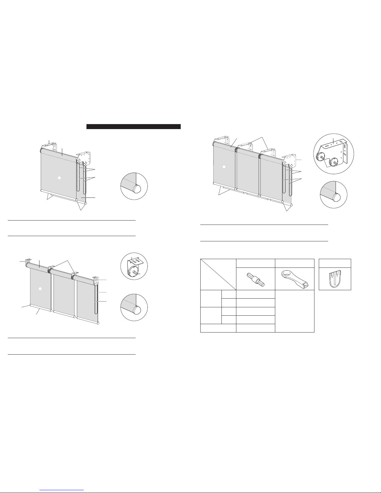
* The figure shows an one-sided
operation (right).
Double Bracket
Roller Pipe
Screen
1)
2)
3)
Weight Bar
Weight Bar Cap
Ball Chain
4)
5)
6)
Ball Chain Connector
7)
P. 4
■ Double Type
■ Link Type
<Wrapping Type>
<Wrapping Type>
Component
*The figure shows a right operation.
* Regarding the size of Side Holder and Link Bracket differs depending on the size of product and the
specifications of the screen.
Side Holder
Roller Pipe
Screen
1)
2)
3)
Weight Bar
Weight Bar Cap
Metal Ball Chain
4)
5)
6)
Ball Chain Connector
Link Bracket
Link Joint Pin
7)
8)
9)
Component
Product View and Part Names
3)
4)
6)
7)
9)
8)
5)
1)
1)
2)
3)
4)
7)
6)
3)
5)
2)
1)
8)
■ Accessories
■Optional Parts
P. 5
Link Joint Pin *1 Winder *2
*1 Used with a link type or a link double type.
*2 Keep carefully together with the instruction manual.
Side Holder Cover
* Used only with a link type.
■ Link Double Type
<Wrapping Type>
Double Bracket
Roller Pipe
Screen
1)
2)
3)
Weight Bar
Weight Bar Cap
Metal Ball Chain
4)
5)
6)
Ball Chain Connector
Link Double Bracket
Link Joint Pin
7)
8)
9)
Component
*The figure shows a right operation.
Component
Product Width
[mm]
Link Type
1 piece
2 pieces
2 pieces
4 pieces
ー
1 piece
Double Type
Link Double
Type
2-unit
3-unit
2-unit
3-unit
3)
4)
7)
6)
9)
5)
1)
8)
8)
2)
Page 4
P. 6
Installation Type
Installation and Detachment of a Double Type
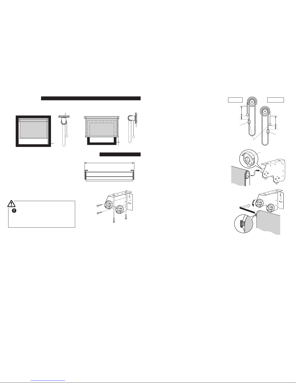
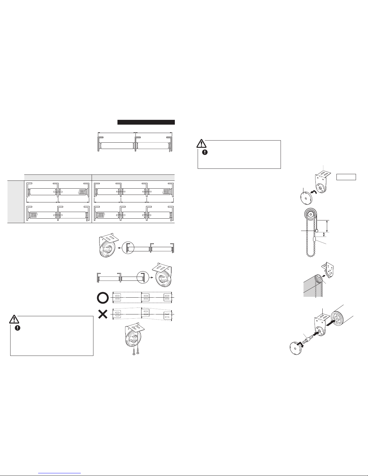
(1)Determine the installation locations of the
brackets so that the distance between the
brackets is the same as the width of the product that you ordered.
(2)Mount Double Brackets with screws.
(3)Install the screen.
* The method of lowering the roll screen differs depending upon whether
it is installed on the window side or the room side.
* The figure shows an
one-sided operation (right).
Use fixing screws that are suitable for
the strength and the material of the wall
or window frame to which the brackets
are to be fixed.
Caution
< Ceiling Attachment>
Install inside of a window frame.
<Wall Attachment>
Install on a wall or outside of a window frame.
Window
frame
Wall Attachment
Ceiling
Attachment
Product Width
Window
frame
Wall
Ceiling
P. 7
2)Insert the dowel (transparent) at the end of
the screen into Side Holder on the chain
side.
* Do not install the both screens at once.
* The position of Side Holder on the chain side
differs depending upon the operating position.
3) Install the black knob on the roll screen body
onto Side Holder on the opposite side the
chain as the red part can be seen at the front.
Once the screen is correctly in place, turn the
dial in the “CLOSE” direction until it clicks.
* Install the screens one at a time, and check to
see if they are parallel to each other.
1) Pull down the screen 5 to 10 cm, then set the
chain as the position of Chain Connector is
located on the rear side, then attach Chain
Connector is about 3 cm below Bottom Bar.
The direction of the chain which of the screen
installed on the room side is the opposite of
the above.
About 3cm
Chain
Connector
5-10cm
About 3cm
5-10cm
Chain
Connector
Bottom Bar
Side Holder on the
chain side
After inserting the dowel,
rotate the dial.
(4)Finally, open and close the screen two or three
times, and check their operation.
(5)How to remove the screen
1) Pull down the screen 5 and 10 cm and stop
it.
2) Rotate the dial of Side Holder on the opposite
side the chain until it stops in the “OPEN”
direction.
3)Remove a roll screen body slowly with both
hands. Also, take care that the chain does
not drop.
* Do not remove the both screens at once.
Room side Window side
Page 5
P. 8
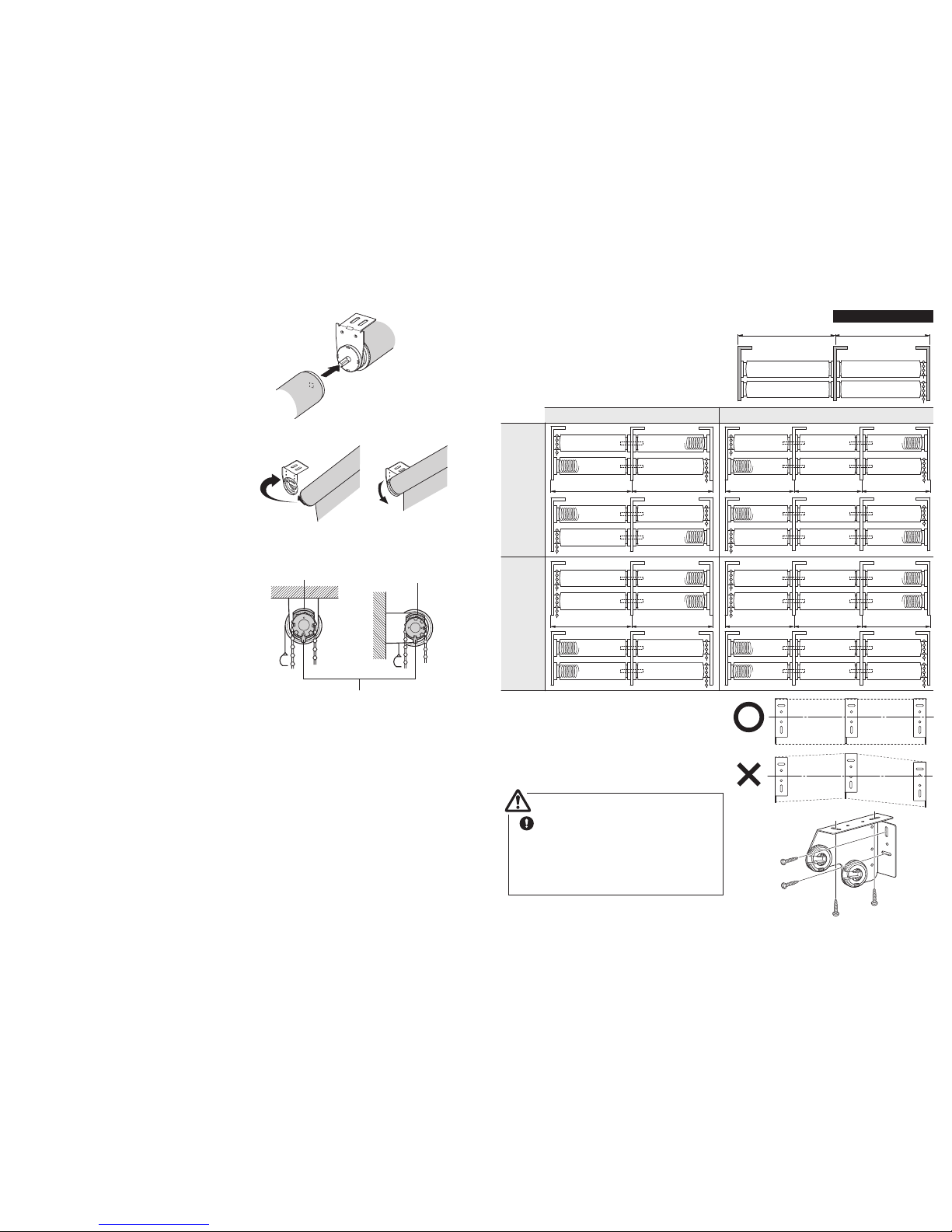
(1)Determine the installation locations of the
brackets so that the distance between the
brackets is the same as the width of the product
that you ordered. The direction of each Link
Bracket is shown below.
* The illustration applies to a ceiling attachment. In the
case of a wall attachment type, install the brackets
on the wall using the same procedure.
(2)Mount End Side Brackets with screws.
If you install the brackets while they are bent,
the screens are liable to move sluggishly or
drop off.
Installation and Detachment of a Link Type
One
Side
Operation
2 Units Link 3 Units Link
W2 W1 W2W3 W1
* For right operation, install the brackets on the left
side as the part shown at right.
* For left operation, install the brackets on the right
side as the part shown at right.
<Right operation >
<Left operation>
Use fixing screws that are suitable for
the strength and the material of the wall
or window frame to which the brackets
are to be fixed.
Be sure to install each Side Holder
using at least two fixing screws.
Caution
W2 W1
P. 9
(3)Install the screen.
* The illustration applies to a ceiling-attachment type
(right operation).
Install the screen from the chain side.
Use the following sequence otherwise
you will be unable to install the screen.
Caution
2) Pull down the screen 5 to 10 cm, then set the
chain as the position of Chain Connector is
located on the rear side, then attach Chain
Connector is about 3 cm below Bottom Bar.
3)Insert the dowel (transparent) on the end of
the screen into Side Holder (right side).
* For left operation, insert the dowel into Side
Holder on the left side.
4) While holding the screen, insert Link Joint Pin
into Link Bracket, and then pass it through the
hole in the roll screen body side. Once you
have inserted Link Joint Pin to the rear, install
the cover while rotating it.
* After installing the cover, check to see if it has
been tightened securely.
1)Remove the cover of each Link Bracket
(other than Side Holders at both ends) on
the side opposite the chain.
Dowel
(transparent)
About 3cm
Chain
Connector
5-10cm
Link Bracket
Cover
Link Bracket
Link Joint Pin
Chain side
Bottom
Bar
Page 6
P.10
5) Install the screen on the opposite side the
chain. Fit the hole in the roll screen body
over Link Joint Pin protruding from Link
Bracket.
* In the case of three links, repeat the work of
steps 4) and 5).
* Install the screens as of they are the same height.
6) Install the black knob on the roll screen body to
Side Holder (left side) to ensure that the red
part is visible at the front. Once the screen is
correctly in place, turn the dial in the “CLOSE”
direction until it clicks.
7)
Set Ball Chain cover at the top.
*
Push the tab on the ball chain cover to the side
opposite the screen, and while keeping it pressed,
turn the cover through 90°.
<Ceiling Attachment> <Wall Attachment>
Ball chain cover
Ball chain cover
(4)Finally, open and close the screen two or three
times, and check their operation.
(5)How to remove the screen
1) Pull down the screen 5 and 10 cm and stop
it.
2) Rotate the dial of Side Holder on the opposite side the chain until it stops in the “OPEN”
direction.
3) Remove a roll screen body slowly with both
hands. Remove the cover and Link Joint Pin
of the link section, and then remove the
screen, while taking care that neither the
screen nor the chain drops.
Push this tab to the opposite side
the screen, and while keeping it pressed,
turn the cover through 90°.
P. 11
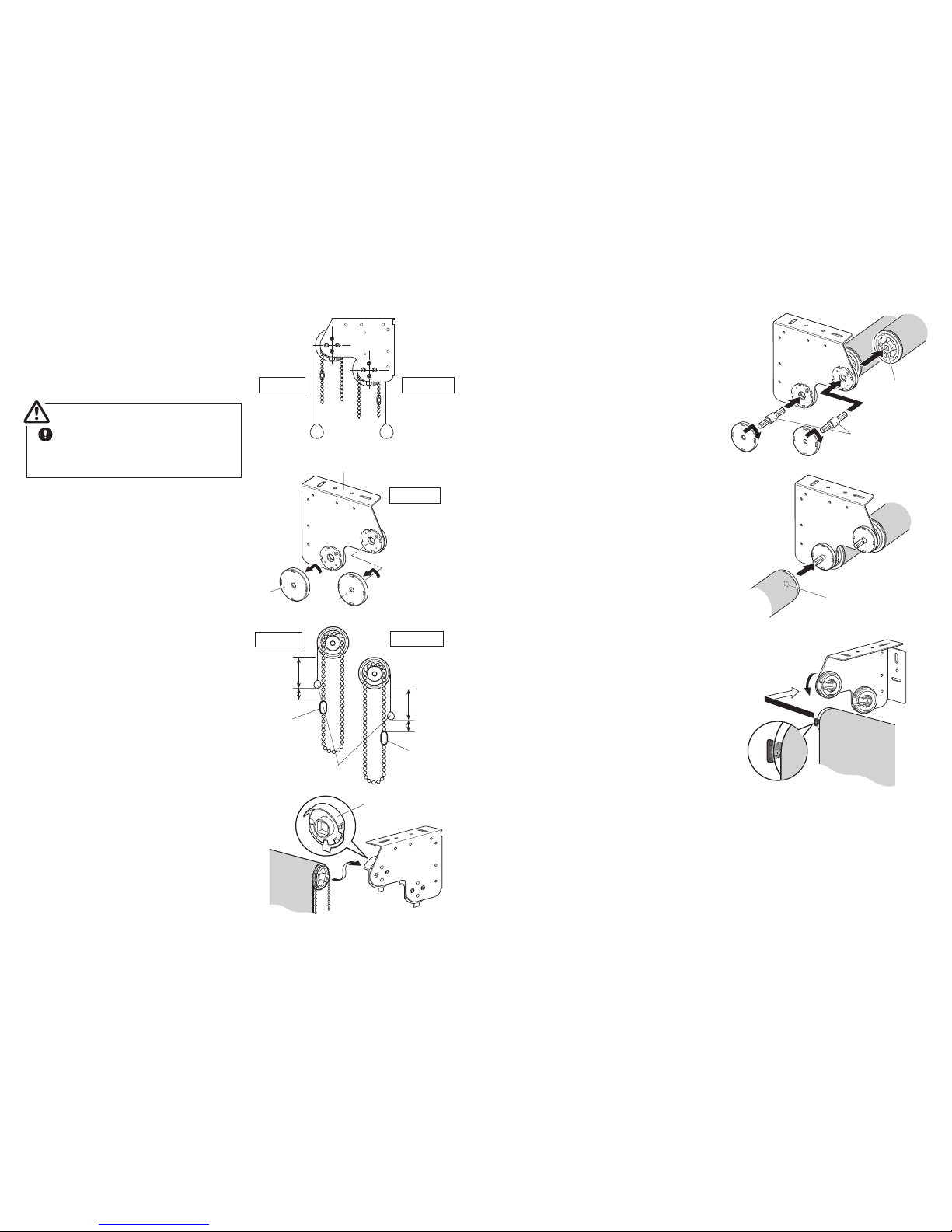
(1)Determine the installation locations of the
brackets so that the distance between the
brackets is the same as the width of the product
that you ordered. The direction of each Link
Bracket is shown below.
(2)Mount End Side Brackets with screws.
If you install the brackets while they are bent,
the screens are liable to move sluggishly or
drop off.
Installation and Detachment of a Link Double Type
One
Side
Operation
Both
Sides
Operation
2 Units Link 3 Units Link
W2 W1
Use fixing screws that are suitable for
the strength and the material of the wall
or window frame to which the brackets
are to be fixed.
Be sure to install each Side Holder
using at least two fixing screws.
Caution
Wall Attachment
Ceiling
Attachment
W2 W1 W2W3 W1
W2 W1 W2W3 W1
Page 7
P.12
(3)Install the screen.
* The method of lowering the roll screen on the
window side differs from that of the roll screen on
the room side.
* The figure shows an
one-sided operation (right).
Install the screen from the chain side.
Use the following sequence otherwise
you will be unable to install the screen.
Caution
1)Remove the cover of each Link Double
Bracket (other than Side Brackets at both
ends) on both the chain side and the side
opposite it.
Link Double Bracket
2) Pull down the screen 5 to 10 cm, then set the
chain as the position of Chain Connector is
located on the rear side, then attach Chain
Connector is about 3 cm below Bottom Bar.
The direction of the chain which of the
screen installed on the room side is the
opposite of the above.
3)Insert the dowel (transparent) at the end of
the screen into Side Holder on the chain
side.
* Do not install some screens at once.
* The position of Side Holder on the chain side
differs depending upon the operating position.
5-10cm
About 3cm
Chain
Connector
Chain
Connector
About 3cm
5-10cm
Cover
Room side
Room side
Window side
Window side
Chain side
Side Holder on the
chain side
Bottom Bar
P.13
4) While holding the screen, insert Link Joint Pin
into Link Bracket, and then pass it through
the hole in the roll screen body side. Once
you have inserted Link Joint Pin to the rear,
install the cover while rotating it.
* After installing the cover, check to see if it has
been tightened securely.
* Do not install some screens at once.
Insert Link Joint
Pin into the hole.
5)Remove the screen on the side opposite the
chain. Fit the hole in the roll screen body
over Link Joint Pin protruding from Link
Double Bracket.
* In the case of three links, repeat the work of
steps 4) and 5).
* Install the screens as of they are the same height.
6) Install the black knob on the roll screen body
onto Side Holder on the opposite side the
chain as the red part can be seen at the front.
Once the screen is correctly in place, turn the
dial in the “CLOSE” direction until it clicks.
* Check to see if Roller Pipes are parallel to
each other.
(4) Finally, open and close the screen two or three
times, and check their operation.
After inserting the dowel,
rotate the dial.
Link Joint Pin
Insert Link Joint Pin.
Page 8
P.14
(5)How to remove the screen
1) Pull down the screen 5 and 10 cm and stop
it.
2) Rotate the dial of Side Holder on the opposite side the chain until it stops in the
“OPEN” direction.
3) Remove a roll screen body slowly with both
hands. Remove the cover and Link Joint Pin
of the link section, and then remove the
screen, while taking care that neither the
screen nor the chain drops.
* Remove the screens one at a time.
P.15
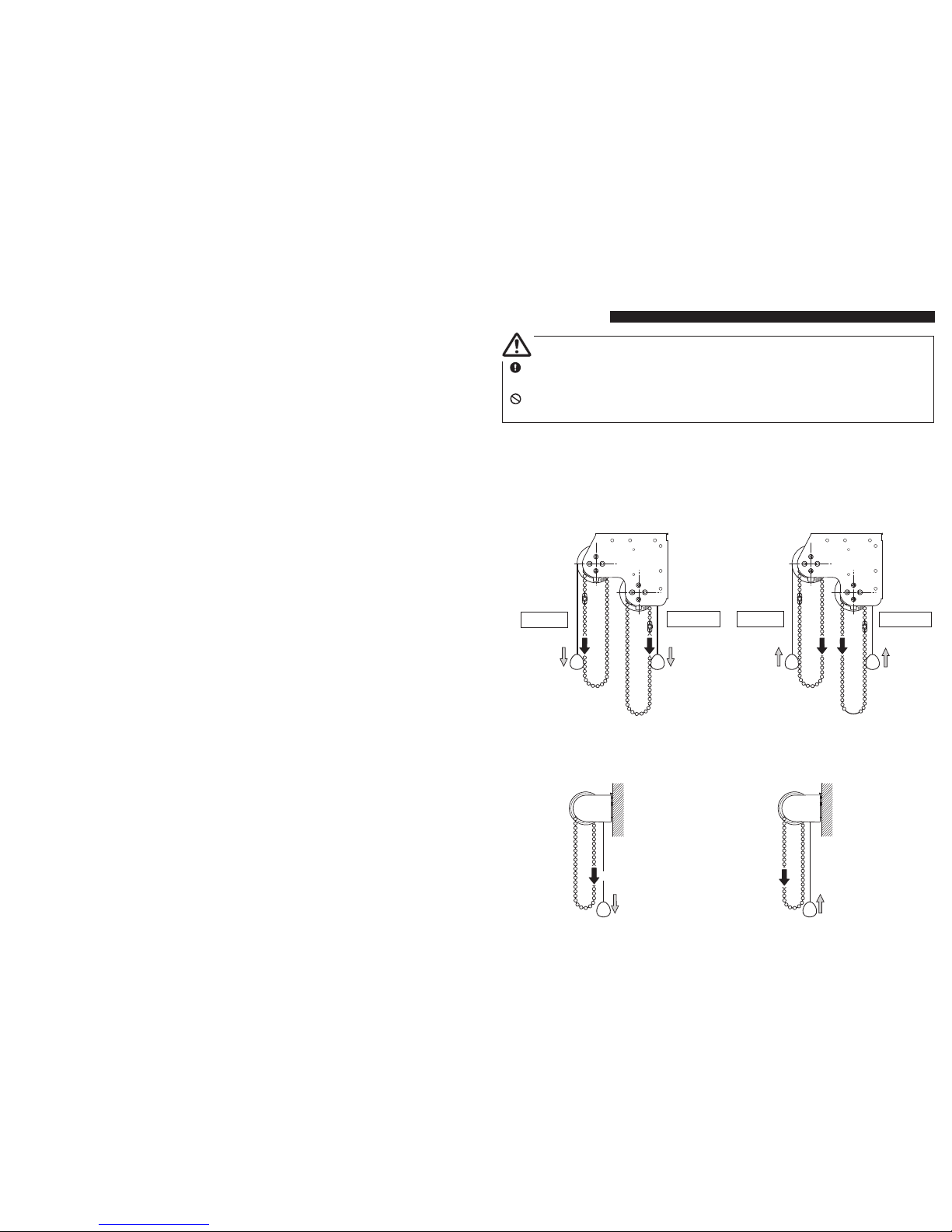
<Link Type>
■ How to close a screen
●
Pull the back side of Ball Chain downward.
■ How to open a screen
●
Pull the front side of Ball Chain downward.
How to Operate
<Installation and Detachment of a Double Type / Link Double Type>
Caution
Make sure to pull Ball Chain slowly when using the product. If Ball Chain is pulled quickly,
the product may not roll up properly.
Please do not hang from Screen or Ball Chain. The product may fall down.
■ How to close a screen
●
To lower the screen on the room side, pull
down the front Ball Chain.
●
To lower the screen on the window side,
pull down the rear Ball Chain.
■ How to open a screen
●
To raise the screen on the room side, pull
down the rear Ball Chain.
●
To raise the screen on the window side, pull
down the front Ball Chain.
Room side
Window side
Room side
Window side
Pull
Pull
Pull Pull Pull
Pull
Page 9
P.16
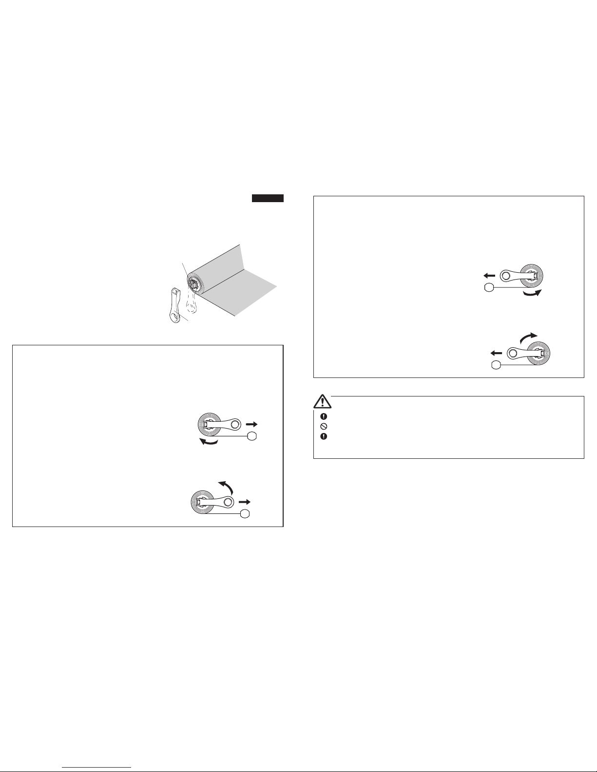
How to Adjust the Screen Operation Force and the Ascent Speed
■ Lighter roll up
●
Turn Winder 1-2 times clockwise while pulling
Winder as directed and unlocking the speed.
<Link type right operation>
<Double type (window side screen) right operation>
<Link double type (window side screen) right operation>
<Double type (room side screen) left operation>
<Link double type (room side screen) left operation>
(1)Remove the screen.
* To remove the screen, refer to the removal method
that corresponds to the specifications of the screen.
(2)Align Winder (provided with the blind) with the
black knob on the screen that you removed. In
the case of the following product types, carry
out adjustment according to the types.
* In the case of a link type / double link type, adjust
the screen on the side opposite the chain.
Winder
Black knob
While pulling
Tur n
clockwise
■ Heavier roll up
●
Turn Winder 1-2 times counter- clockwise while
pulling Winder as directed and unlocking the
speed.
While pulling
Tur n
counter- clockwise
P.17
■ Lighter roll up
●
Turn Winder 1-2 times counter- clockwise while
pulling Winder as directed and unlocking the
speed.
(3)To install the screen, refer to the installation method that corresponds to the specifications
of the screen
While pulling
Tur n
counter- clockwise
■ Heavier roll up
●
Turn Winder 1-2 times clockwise while pulling
Winder as directed and unlocking the speed.
While pulling
Tur n
clockwise
Winder does not turn if not pulled to unlock direction as illustrated.
Do not turn more than twice at once.
Hold Winder securely especially while pulling to unlock direction. If Winder is released
while pulled to unlock direction, Roller Pipe blows off Winder, and it may cause
accidents or injuries.
Caution
<Link type left operation>
<Double type (window side screen) left operation>
<Link double type (window side screen) left operation>
<Double type (room side screen) right operation>
<Link double type (room side screen) right operation>
Page 10
P.18
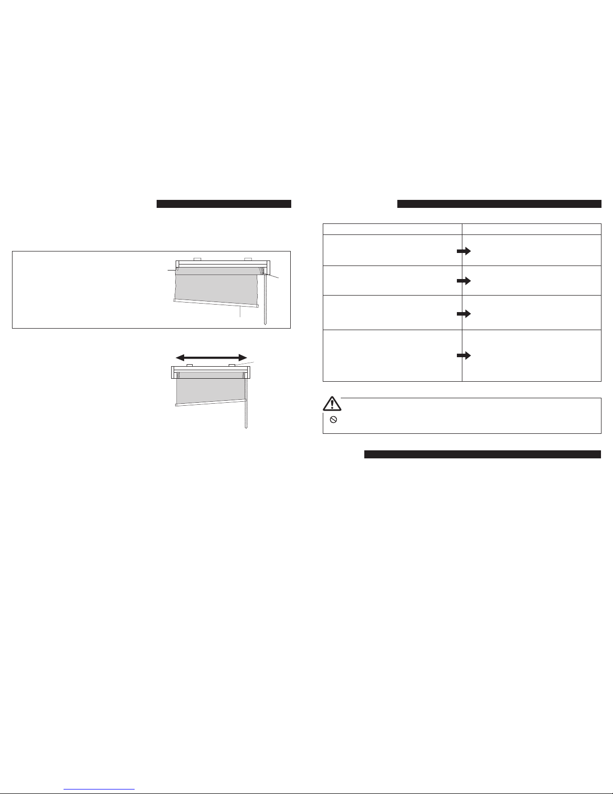
Fixing Improper Rolled up Screen
●
When a screen is not rolled up properly, it may cause damages to the screen or the product.
TOSO Roller Blinds are inspected and adjusted to operate properly when delivered, however
if a roller blind rolls improperly, follow below instruction.
<What is Improper Rolling?>
1) Screen edge is misaligned.
2) Screen edge touches a side holder.
3) Weight Bar is not horizontal.
■ How to fix improper rolling?
(1) Make sure a product is installed correctly.
1) Is a product installed horizontally?
2) Are Brackets placed at correct at position?
* Reinstall the product if it is not installed properly.
(2)Slowly operate Ball Chain and pull down the
screen to the bottom, then once again roll up
the screen.
(3)Repeat the instruction (2) for 2-3 times.
1) Install horizontally
1)
3)
2)
2)
Brackets are
placed in
correct
positions
(Refer to P.6,
P.8 and
P.11.)
Troubleshooting
Cleaning
●
For regular care, dust with a feather duster or a hand mop.
●
To avoid discoloration, avoid cleaning the screen with water or using it in a location
susceptible to splashing water.
Do not disassemble or modify the mechanism inside Roller Pipe.
Caution
Phenomenon Actions
●
When the screen does not stop at the
desired height, and rolls down.
●
When the screen does not stop at the
desired height, and rolls up.
●
When Ball Chain is pulled, it does not
operate smoothly with an unusual noise, or
does not operate at all.
●
When the screen does not descend
●
Repeatedly carry out the adjustment
described in “Lighter roll up” on P.16 or
P.17.
●
Repeatedly carry out the adjustment
described in “Heavier roll up” on P.16 or
P.17.
●
It is likely that the position of Ball Chain
Cover is incorrect. Carry out the procedure set out on P.10.
●
It is likely that this is because the dial of
Side Holder is not fully in the “CLOSE”
condition.
Turn the dial in the “CLOSE” direction
until it stops completely.
P.19
 Loading...