

TOSO Design Blind 50 Drum Type, Design Blind 35 Drum Type, Design Blind 50T Drum Type, Design Blind 35T Drum Type Instruction Manual

I−08091601
INDEX
Caution ...................................................................................................................... 2
Product View and Part Names ................................................................................ 4
Installation and Detaching....................................................................................... 5
Operation Methods ................................................................................................. 8
Changing Operation Position .................................................................................. 9
Troubleshooting...................................................................................................... 12
Maintenance Sticker.............................................................................................. 13
Cleaning ................................................................................................................. 14
Instruction Manual
Design Blind
Guide for Distributors and Installation Contractors
This manual contains information for a user to safely operate this product.
Please provide this manual to a customer.
No.I − 08091601
Thank you for purchasing TOSO products. To ensure safe use of this product,
please read the following thoroughly and keep this manual stored.
Design Blind 50/50T Drum Type
Design Blind 35/35T Drum Type
Warning
P. 2 P. 3
Japan Blind Industry
Association
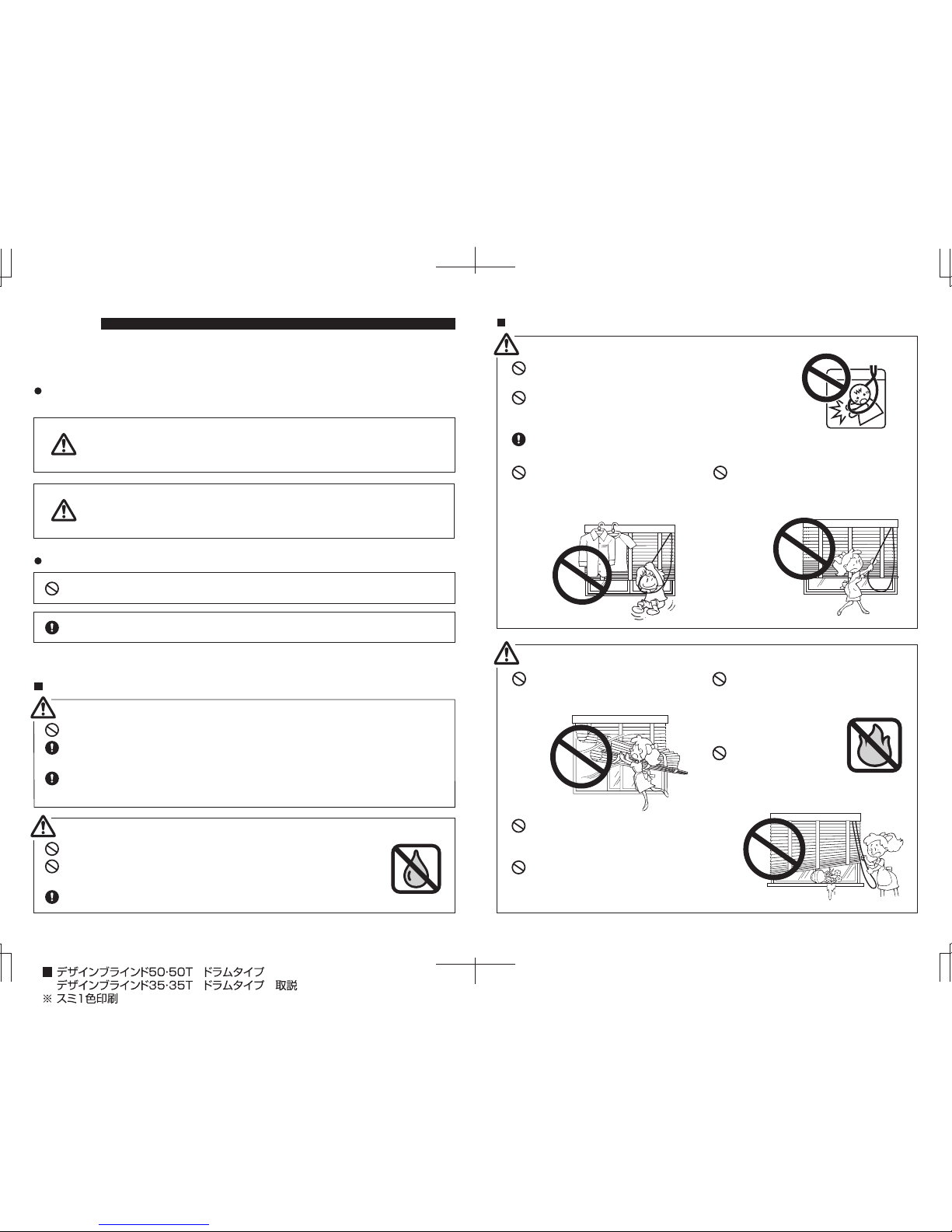
Please keep the cord or the chain where children cannot
reach.
Please avoid actions which may result in the cord or the
chain entangling the body or becoming hooked onto
something. This may cause an accident.
When not in use, please take the cord and put away the
handling cord by wrapping it around the safety hook.
Please do not hang from or pull on
this product. This may damage the
product or cause it to fall down.
Please do not operate the product with
sudden or forceful motion. This may
damage the product or cause it to fall
down.
Safety During Use (Please read thoroughly)
Caution
When there is strong wind, please
either close the window or have the
Slat completely opened up.
Please do not dismantle the
mechanical assembly or lubricate the
moving parts of this product.
Physical damage or
malfunction of the
product will occur.
Please do not use this
product around open
flames.
Please remember to always use the Operation
Cord when operating this product. Please do
not attempt to move the Slat or Bottom Rail
directly.
Please do not place any fragile objects or
objects that may interfere with operation near
the screen.
CAUTION
∗ This manual contains cautions and instructions for safe use of the product.
Please read it carefully before using to ensure appropriate use.
This document illustrates the dangers of using this product without taking necessary
precautions. Please refer to the symbols below for different types of safety points.
This document illustrates safety points to be followed using the symbols below.
Illustrates that if this product is misused, there are dangers of serious
injuries or possible fatal accidents.
Illustrates that if this product is misused, there are dangers of
casualties or possible physical damage of the product.
Illustrates specific actions which are prohibited.
Illustrates specific guidelines which must be followed.
Screws provided are for xylem only. Do not use on materials other than xylem.
Check the foundation base and strength of the material before installing this product. If
not installed properly to the foundation base, there are dangers of it falling.
Install this product as instructed with the necessary quantity of brackets. Otherwise the
product may fall.
Warning
Caution
This product is intended for indoor use. Please do not use it for outdoor purposes.
Locations subject to high temperatures and high humidity, or areas where
water may leak, should be avoided.
Make sure to install this product horizontally.
Precautions upon installing the product (Please read before installation.)
Warning
Caution
P. 4 P. 5
Product View and Part Names Installation and Detaching
<Design Blind 50T/Design Blind 35T>
(Valance/Ladder Tape)
Bottom Rail
Bracket
Head Rail
Slat
Ladder Tape
Operation Cord
Valance
Maintenance
Sticker
Bottom Rail
Bracket
Head Rail
Slat
Ladder Cord
Operation
Cord
Valance
Maintenance
Sticker
<Design Blind 50/Design Blind 35>
(Valance/Ladder Cord)
Product Weight
Components Parts
Components
Name
Safety TasselBracket
Fixing Screw
(round head Ø3.5 x 20)
1
400−1200
1210−2400
2
3
4
6
Product Width
(mm)
Wood 50 mm Wood 35 mm Leather Taste Fabric Aluminum
8.5 kg 8.7 kg 7.9 kg 6.6 kg 5 kg
Product Width 1,800 mm x Product Height 1,830 mm
Screws provided are for xylem only. Do not use on materials other than xylem.
Be sure to attach the brackets securely to the foundation base.
Caution
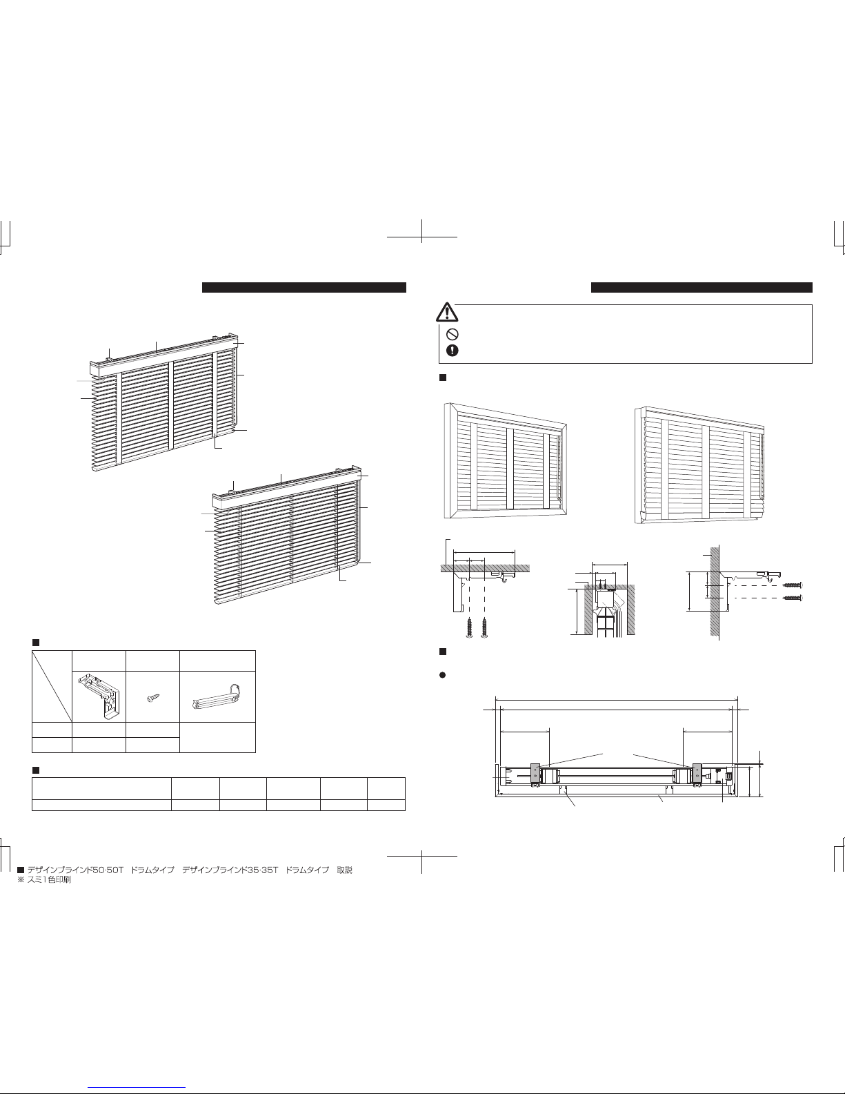
Installation Method Brackets can be installed on a ceiling or a surface.
Bracket Position
<When the product width is 500mm or less>
Install the brackets within 50-80mm of the edges of the Head Rail.
<Ceiling Attachment> <Front Attachment>
Attaching surface
Attaching surface
(When a curtain box is attached)
69.5
18 17
Box height
70
1718
10
120
Attaching surface
(mm)
(mm)
15.5
14.545
(mm)
Valance width
Product width (W)
Gear Box
Valance Holder
Bracket
Valance
115 115
15
15
94
87
2
Head Rail

P. 6 P. 7
Bracket installation
Follow the illustrations for "Installation Method" on p.5 and use the included bracket
fixing screws to install the brackets.
<When the product width is 510mm or more>
Install the brackets within 50-80mm of the edges of the Head Rail.
If there are three brackets, be sure to install them at intervals that are as equally spaced as
possible.
Install so that the extended flange on the
Head Rail touches the back plate of the
brackets as shown in the illustration to
the right.
If installed incorrectly, the product may
fall.
After installing the main unit, make sure the main unit is secured to the brackets. If the
installing is insufficient, the bracket release button will be pressed in.
Caution
Installing the main unit
With the slats in the stacked position, latch
the temporary stopper hook onto the Head
Rail.
Push the Head Rail in until it clicks into place.
Installing the Valance
∗ If the optional "Valance Joint Fixtures" are specified, the Valance installing procedure will vary.
When removing the product from the brackets, be sure to support it with your hand.
Caution
Latch the protrusion on the lower portion of
the Head Rail onto the hook on the bottom of
the Valance Holder.
While holding in the button on the lower
portion of the Valance Holder, push in on the
Head Rail and latch the hook on the upper
portion of the Valance Holder onto the upper
portion of the Head Rail.
When the Valance is installed onto the Head Rail, do not move the Valance position.
Before adjusting the position, first remove the Valance and then re-mount.
Warning
Latch the protrusion on the lower portion of
the Head Rail onto the hook on the bottom of
the Valance Holder.
When using a Back Valance
Valance width
Product width (W)
According to the number of the ladder tapes,
the intervals are evently distributed.
Gear Box
Valance Holder
Valance Holder
Bracket
Valance
140 140
15
15
94
87
2
Latch onto the
temporary
stopper hook
Push in and up
Head Rail
Correct attachment
Incorrect attachment
Back plate of
the bracket
Extended flange
on the Head Rail
Pull forward
While pressing
the release
button
Head Rail
Uninstalling the main unit
With the slats in the stacked position, grasp
the main unit and pull the Head Rail forward
while pressing the bracket release button.
Remove the main unit from the temporary
stopper hook.
Latch the protrusion on the lower
portion of the release Head Rail
onto the hook on the bottom of
the Valance Holder.
Latch the hook on the upper portion of the Valance
Holder onto the upper portion of the Head Rail.
Hold in the button on the lower
portion of the Valance Holder
Head Rail
Head Rail
Attaching surface
Attaching surface

∗ Cannot be attached on the same position as
the brackets.
While holding in the button on the lower
portion of the Valance Holder, push in on the
Head Rail and latch the hook on the upper
portion of the Valance Holder onto the upper
portion of the Head Rail.
When the Valance is installed onto the Head Rail, do not move the Valance position.
Before adjusting the position, first remove the Valance and then re-mount.
Warning
Operation Methods
Tassel and safety hook mounting
This Safety Tassel is a part for preventing
unexpected accidents such as the Operation
Cord becoming wrapped around the neck or
body of a child.
Attach the Safety Tassel to the Operation Cord
using the included ring and tie the Operation
Cord in a place where children cannot reach.
Adjusting the angle of the slats
Raising and lowering the blind
Pull down on section A of the Operation Cord and the blinds will pull down.
Pull down on section B of the Operation Cord and the blinds will pull up.
Pull on section A or B of the
Operation Cord
to adjust.
∗ The stopper will engage if the bottom rail hits an obstacle
while the slats are being lowered. Remove the obstacle and
pull on section B of the
Operation Cord
to release the stopper.
∗ When the slats reach the lowest position the stopper will
engage. This is to prevent the raising/lowering tape from
being wound in the wrong direction and is not a defect.
∗ If the
Operation Cord
is pulled forcefully when the stopper has
engaged, damage to the product will occur.
P. 8 P. 9
Changing Operation position
When changing the left-right operation be sure not to hurt yourself with the end and
cut out of the head rail or with the slats.
Caution
Follow the below steps to change the left operation to the right, right operation to the left.
In the stacked position, remove the main unit.
∗ Will be easy to remove by using needle-nose
pliers, etc. to push in the resin portion.
Remove the Head Cap on the opposite side of
the Head Rail in the same manner.
∗ Be sure the Shaft does not come out of the
drum portion.
<When changing right operation to left operation>
Operation Cord
Ring
Safety Tassel
Head Rail
Gear Box
Loosen the screw
Remove
the Shaft
Gear Box
Remove the Gear Box
Push in on the resin in the hole
on the bottom portion
Head Cap
A
B
Remove the screws in the part connecting the
Shaft and the Gear Box inside of Head Rail,
then remove the Shaft and Gear Box. Push in
the resin portion on the bottom of the Head
Rail while sliding the Gear Box out of the Head
Rail.

Remove the Gear Box cover from the Gear
Box taken from the Head Rail.
∗ The latches are easier to remove if removing
the bottom one then the upper one. Remove
the two pulley drums from the main Gear
Box unit. Insert the Operation Cord into the
groove of the pulley and wrap it around the
back.
∗ When removing the Gear Box, the pulley
drums may come off. Be sure to not lose
them.
Gear Box
Remove the
Gear Box Cover
Remove the Cord Guide
Roller from Gear Box
Latch (Up)
Latch (Down)
P. 10 P. 11
Place the Operation Cord in the specified
position and attach as illustrated.
Reattach the Cord Guide Roller at the rear hole
and attach the Gear Box Cover.
Attach the Cord
Guide Roller
Attach the
Gear Box Cover
Insert the Gear Box on the opposite side of the Head Rail. Confirm that the Shaft is inserted
into the Gear Box, and secure with the screw. Finally, attach the Head Cap to the opposite side
of the Head Rail.
∗ When attaching the Gear Box/Head Cap to the Head Rail, push in until they click into place.
Insert the Shaft and
secure with the screw
Attach the
Head Cap
Attach the
Gear Box
Head Rail

P. 12 P. 13
Troubleshooting Maintenance Sticker
Example
Phenomenon Cause Solution
Screen doesn't
move
Remove the obstacle, raise the screen
a bit and it will move.
There is an obstacle
blocking the bottom rail.
Head Rail
Operation Cord
Your purchased product has an affixed maintenance sticker showing information related to the
product. Please refer to this maintenance sticker when inquiring about the product or for
repairs.
Shows the shipping date.
Shows the product specifications.
Product name
Installation height
Slat code Product
width
Product
height
Operation
position

P. 14
Cleaning
Remove dust by wiping with a hand mop or dry cloth.
If the blinds become dirty, wet a cloth and tightly wring, then lightly wipe the blinds.
 Loading...