

Toslink 14524 User Manual
1

CONTENTS
SAFETY WARNINGS AND GUIDELINES ....................................................................................................................................... 4
INTRODUCTION ................................................................................................................................................................................................ 5
FEATURES .............................................................................................................................................................................................................. 6
PACKAGE CONTENTS ................................................................................................................................................................................. 6
PRODUCT OVERVIEW ................................................................................................................................................................................. 7
Front Panel ..................................................................................................................................................................................................... 7
Rear Panel ....................................................................................................................................................................................................... 7
Keypad Controllers ............................................................................................................................................................................... 10
IR Remote Control ................................................................................................................................................................................. 12
LOCATION PLANNING ............................................................................................................................................................................. 13
CABLE PREPARATION ............................................................................................................................................................................... 14
Ethernet Cables ....................................................................................................................................................................................... 14
Speaker Wires ........................................................................................................................................................................................... 15
RCA Cables ................................................................................................................................................................................................... 15
3.5mm TRS Cables .................................................................................................................................................................................. 16
Mini Toslink® Cable ............................................................................................................................................................................... 16
Trigger Cables ........................................................................................................................................................................................... 16
RS232 Serial Cable ................................................................................................................................................................................. 17
IR Emitters .................................................................................................................................................................................................... 17
INSTALLATION ................................................................................................................................................................................................ 18
Test Installation ....................................................................................................................................................................................... 18
Connecting Multiple Multizone Controllers .................................................................................................................. 18
Connecting the Wallplate Keypad Controllers ........................................................................................................... 19
Connecting External Amplifiers ............................................................................................................................................... 20
Connecting the Speaker Wires ................................................................................................................................................. 20
2

Connecting Analog RCA Source Devices ......................................................................................................................... 21
Connecting Analog 3.5mm Source Device ...................................................................................................................... 21
Connecting a Digital Optical (S/PDIF) Source Device .......................................................................................... 21
Connecting a Digital Audio Source Device ................................................................................................................... 22
Connecting the Triggers ................................................................................................................................................................. 22
Connecting IR Emitters .................................................................................................................................................................... 22
Connecting a Computer Using RS232 ................................................................................................................................ 23
Connecting Power ............................................................................................................................................................................... 23
Test Operation ......................................................................................................................................................................................... 23
Final Installation ..................................................................................................................................................................................... 25
RS232 SERIAL CONTROL ........................................................................................................................................................................ 26
SPECIFICATIONS ........................................................................................................................................................................................... 32
REGULATORY COMPLIANCE ............................................................................................................................................................. 33
Notice for FCC ......................................................................................................................................................................................... 33
Notice for Industry Canada .......................................................................................................................................................... 34
3

SAFETY WARNINGS AND GUIDELINES
This device is intended for indoor use only.
Do not expose this device to water or moisture of any kind. Do not place drinks or
other containers with moisture on or near the device. If moisture does get in or on
the device, immediately unplug it from the power outlet and allow it to fully dry
before reapplying power.
Do not touch the device, the power cord, or any other connected cables with wet
hands.
Do not expose this device to excessively high temperatures. Do not place it in, on,
or near heat sources, such as a fireplace, stove, radiator, etc. Do not leave it in direct
sunlight.
This device ventilates excessive heat through the slots and openings in the case. Do
not block or cover these openings. Ensure that the device is in an open area where
it can get sufficient airflow to keep from overheating.
Do not place or install this device in an area where it can be exposed to excessive
amounts of dust, humidity, oil, smoke, or combustible vapors.
Prior to operation, check the unit and power cord for physical damage. Do not use if
physical damage has occurred.
Take care to prevent damage to the power cord. Do not allow it to become
crimped, pinched, walked on, or become tangled with other cords. Ensure that the
power cord does not present a tripping hazard.
Before plugging the unit into a power outlet, ensure that the outlet provides the
same type and level of power required by the device.
This device uses a grounded power cord and requires a ground connection for safe
operation. Ensure that the power source has a proper ground connection. Do not
modify the plug or use a "cheater" plug to bypass the ground connection.
Ensure that power is turned off and disconnected before making any electrical
connections.
4

Disconnect the unit from the power source when replacing the fuse. Replace the
fuse only with the same type.
Unplug this device from the power source when not in use.
Never unplug the unit by pulling on the power cord. Always grasp the connector
head or adapter body.
Remove the batteries from the controller if it will go unused for a lengthy period of
time.
Clean using a soft, dry cloth only. Do not use chemical cleaners, solvents, or
detergents. For stubborn deposits, moisten the cloth with warm water.
This device has no user serviceable parts. Do not attempt to open, service, or
modify this device.
INTRODUCTION
Thank you for purchasing this Multizone Home Audio Controller and Amplifier Kit!
This device is a full function audio system, which combines the functions of a preamplifier,
a full 6x4 audio matrix, and four 70 watt power amplifiers for driving speakers in up to four
separate zones. Additionally, up to three multizone amplifiers, including the 10761 6x6 50-
watt model, can be combined to provide full signal switching and amplification to up to 16
different speaker zones!
For best results, please read and understand this manual thoroughly before installation,
paying particular attention to the safety warnings and guidelines. Keep this manual in a
safe place for future reference.
5

FEATURES
Two pairs of analog stereo RCA inputs
One analog 3.5mm TRS stereo input
One combination analog 3.5mm TRS/digital optical Mini Toslink® stereo input
Two RJ45 digital inputs for use with audio source devices, such as the model 13358
Multizone Source Keypad
Four separate stereo 70-watts per channel into 4-ohms audio amplifiers
Each amplifier can be bridged to produce 140-watts into an 8-ohm load
Can be expanded with up to two additional 6x4 or 6x6 multizone controllers
PA override feature to broadcast to all zones
12-volt triggers for each zone
Includes IR remote control and four remote keypad controllers
Includes rack mount ears for installation into a standard 19" equipment rack
PACKAGE CONTENTS
After receiving the product, please inventory the contents to ensure you have all the
proper parts, as listed below.
1x 6x4 multizone home audio controller/amplifier
4x Keypad controllers
1x Keypad in-wall hub connection plate
1x Infrared remote control
1x Expansion ribbon cable
1x Rack mounting kit
1x AC power cord (IEC 60320 C13 to NEMA 5-15)
1x User's manual
6
PRODUCT OVERVIEW
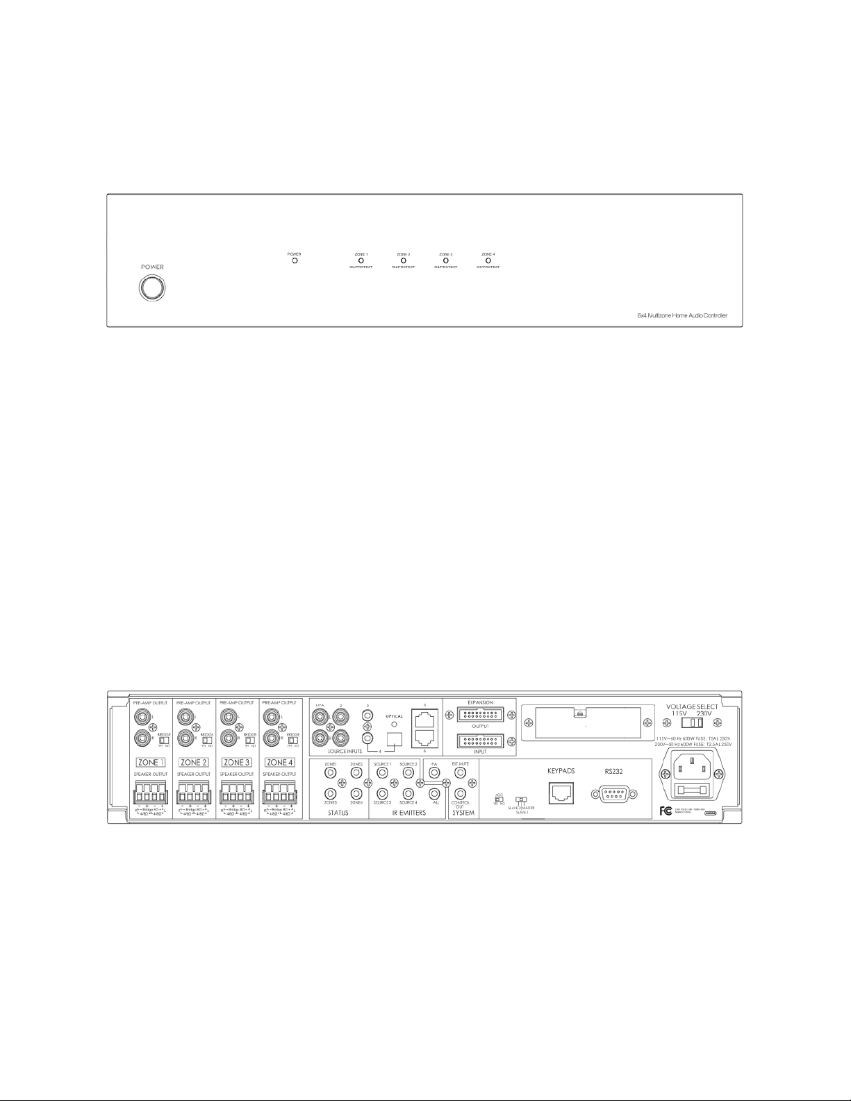
Front Panel
1. Power Button: Depress the power button to turn the controller/amplifier on or off.
Note that when the controller is powered on, each individual zone will remain in
standby until its keypad is activated.
2. Power LED Indicator: This LED is off when the controller is powered off and
illuminates red when power is applied.
3. Zone Status LED Indicators: These multicolor LEDs illuminate blue whenever the
individual zone keypad is activated. If the amplifier is driven into distortion, the
audio signal will cut off and the LED will change color to red, indicating that you
should immediately reduce the volume level using the zone keypad.
Rear Panel
4. Preamp Outputs: Each of these four stereo pairs of RCA jacks is used to connect to a
dedicated power amplifier, instead of using the built-in amplifier.
5. Bridge Switch: Each of these slide switches is used to switch the zone between
Stereo and Bridged Mono mode. In Stereo mode you can connect 4-ohm or 8-ohm
speakers, but in Bridged Mono mode you can only connect an 8-ohm load.
7

6. Speaker Output: Each of these removable Euroblock terminal blocks is used to
connect a pair of speakers in Stereo mode or a single speaker in Bridged Mono
mode.
7. Source Input 1: This analog stereo RCA pair is used to connect to the line level
output of an audio device, such as a CD player. When a 12VDC trigger signal is
detected on the
8. Source Input 2: This analog stereo RCA pair is used to connect to the line level
output of an audio device, such as a CD player.
9. Source Input 3: This analog stereo 3.5mm TRS jack is used to connect to the line
level output of an audio device, such as a CD player, or the headphone output of a
mobile device.
10. Source Input 4: This 3.5mm TRS jack can be used as an analog stereo audio input or
as a digital optical S/PDIF (Mini Toslink®) input. Instead of requiring a physical switch
to change modes, the controller will automatically detect the type of signal and
adjust itself accordingly.
11. Source Inputs 5 and 6: Each of these RJ45 Ethernet jacks is used to connect to a
digital audio source, such as the model 13358 Multizone Source Keypad, using Cat5e
or Cat6 cables.
12. Zone Status: Each of these 3.5mm TS jacks provides a constant 12VDC signal output
System PA
input, the audio on this input is broadcast to all zones.
whenever the corresponding zone is active. This 12-volt signal can be used as a
trigger for motorized devices, such as projector screens, curtains, lights, etc.
13. IR Emitters: Each of these 3.5mm TS jacks is used to connect to an infrared emitter,
which can repeat an IR control signal sent from a remote keypad to control each
source device. The IR repeater function supports single-band IR signals only (those
in the 38kHz range). The ALL jack repeats the IR control signals for all source devices
to a single IR emitter.
14. System PA: This 3.5mm TS jack is used to connect to a 12VDC trigger source. When a
signal is present on this input, the audio from Source Input 1 is broadcast to all
zones.
8

15. System Mute In: This 3.5mm TS jack is used to connect to a 12VDC trigger source.
When a signal is present on this input, the audio output is muted for all zones.
16. System Control Out: Similar to the Zone Status jacks, this 3.5mm TS jack provides a
constant 12VDC signal output whenever any zone is active. This 12-volt signal can be
used as a trigger for motorized devices, such as projector screens, curtains, lights,
etc.
17. Expansion Input and Output: These two ribbon cable connectors are used to
connect to up to two additional 6x4 (14524) or 6x6 (10761) controllers to create up
to 16 distinct zones. Use the included ribbon cable to connect the output of one
controller to the input of the second. A third Controller can then be connected to
the output of the second.
18. AGC Switch: This slide switch controls whether Automatic Gain Control is active or
not. The automatic gain ensures that all the inputs are at the same overall volume
level.
19. Master/Slave Switch: This slide switch determines the functional assignment of this
particular controller in a multi-controller setup. Up to three controllers can be
connected, one of which must be designated the Master, with the other two being
Slave 1 and Slave 2.
20. Keypads Jack: This RJ45 Ethernet jack is used to connect the controller to the
Keypad In-wall Hub Connection Plate, which in turn connects to each individual wall
plate keypad. Use Cat5e or Cat6 Ethernet cable wired to the TIA/EIA-T568B
standard. Ethernet cables are not included.
21. RS232 Port: This DB9 (DE9) female port is used to connect to a PC to provide
automated control of the system. A full reference to the RS232 codes needed to
control the system can be found in the
22. Voltage Select Switch: This slide switch sets the base input voltage to 115V or 230V.
The plastic cover must be removed before the switch position can be changed,
which ensures that the voltage switch cannot be accidentally set to the wrong
position. Make sure the voltage selector switch is set to the correct voltage range
RS232 Serial Control
section of this manual.
before plugging the unit into a power outlet. The fuse should be replaced with the
appropriate type and size whenever the input voltage level is changed.
9
23. AC Power Input Socket/Fuse Holder: This combination power socket and fuse
holder uses the familiar IEC 60320 C14 style and connects using a power cord with a
C13 plug. The fuse is a 250V, 600 watt T5AL type for 115V use and a T2.5AL type for
230V use. Always change the fuse whenever the input voltage is changed.
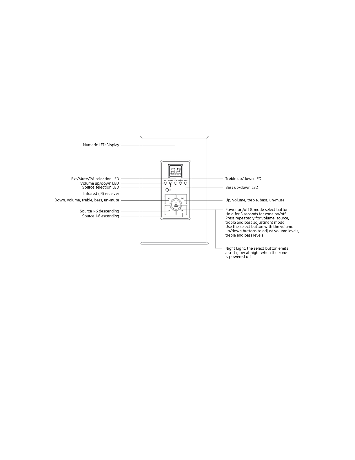
Keypad Controllers
24. LED Display: The digital LED display shows the number of the source device, as well
as the volume, treble, and bass levels.
25. Vol. LED: When illuminated, this LED indicates that the Numeric LED is displaying
the volume level. Use the Up and Down buttons to increase and decrease the
volume level.
26. Source LED: When illuminated, this LED indicates that the Numeric LED is displaying
the source selection.
27. Ext. LED: When illuminated, this LED indicates that the Mute function is enabled or
that a PA broadcast is in progress.
10

28. Treble Mode LED: When illuminated, this LED indicates that the Numeric LED is
displaying the treble level. Use the Up and Down buttons to increase and decrease
the treble level.
29. Bass Mode LED: When illuminated, this LED indicates that the Numeric LED is
displaying the bass level. Use the Up and Down buttons to increase and decrease
the bass level.
30. Infrared (IR) Receiver: The IR "eye" receives the infrared remote control signals.
Signals sent from the included remote control are used to control the wallplate
keypad, while signals from other remote controls are sent back to the Master
Controller, which distributes the signals to the source device via an external IR
emitter (not included).
31. Up Button: Use this button to increase the volume, treble, or bass levels, depending
on which mode is selected. If the zone is muted, pressing this button will unmute it.
32. Down Button: Use this button to decrease the volume, treble, or bass levels,
depending on which mode is selected. If the zone is muted, pressing this button will
unmute it.
33. Previous Source Button: Use this button to cycle backwards through the list of
available sources. For example, if source 4 is currently selected, pressing this button
will change to source 3.
34. Next Source Button: Use this button to cycle forward through the list of available
sources. For example, if source 4 is currently selected, pressing this button will
change to source 1.
35. Select/Power Button: Press and hold this button for about 3 seconds to turn the
zone on or off. When the zone is on, pressing the button will cycle through the
available adjustment modes.
11
 Loading...