


USER MANUAL
TOSIBOX® Lock 100
TOSIBOX
TOSIBOX
TOSIBOX
TOSIBOX
®
Lock 150
®
Lock 200
®
Lock 500
®
Key
1
Version 1.9

TABLE OF CONTENTS
2
1. Regulatory information 4
1.1 TOSIBOX® Lock intended use 4
1.2 Important notice for wireless operation of TOSIBOX® Lock 5
1.3 Safety and hazards 5
1. Informations réglementaires 6
1.1 Utilisation prévue de TOSIBOX® Lock 6
1.2 Avis important concernant le Fonctionnement
sans fil du TOSIBOX® Lock 6
1.3 Sécurité et dangers 7
2. Overview to TOSIBOX® Key and Locks 8
2.1 TOSIBOX® Key 6
2.2 TOSIBOX
®
Locks 9
3. Getting started 16
4. TOSIBOX
®
Lock instructions 17
4.1.1 Deploying Lock in “Lock Mode” 17
4.1.2 Deploying Lock in “Client Mode” 18
4.2 Connecting Locks 19
4.3 Updating the Lock Software 19
4.4 USB Modem settings for the Lock 20
4.5 Internal modem settings for Lock 500i 20
4.6 WLAN settings for Lock 100, Lock 150 and Lock 500 20
4.7 Key connection settings for the Lock 20
4.8 Advanced settings for the Lock 21
4.9 Internet connection priorities 21
4.10 PoE 21
4.11 Service Port 21
4.12 Mounting instructions 24
4.13 Input powering options 26
4.14 Lock 500 - Digital In/Out port with 24V DC out 28
4.15 Lock 500 - Software configurable I/O 28
4.16 Lock 500 - Digital I/O SMS alert 30
5. TOSIBOX® Key instructions 30
5.1 Taking Master Key into use 32
5.2 Renaming and using devices 34
5.3 Adding extra Keys 36
5.4 Remote matching of extra Keys 41
5.5 PUK code for the Key 41
6. TOSIBOX® Mobile Client installation 42
6.1 Mobile Client for Android Devices 42
6.2 Mobile Client for iPhones and iPads 47
7. Troubleshooting 52
7. Dépannage 52
8. Maintenance instructions 53
8. Consignes d’entretien 53
9. Technical data 54
10. Limited Warranty 64
11. Legal Notices 65
11. Mentions légales 65
12. Declarations 66

3
®
Congratulations for choosing TOSIBOX
solution! It consists of modular components
that offer unlimited expandability and flexibility. All products are compatible with
each other as well as internet connection, operator, and device agnostic. The system
works both in internal and external networks.
• TOSIBOX
• TOSIBOX
®
Key is a client used to access the network.
®
Lock is a router with firewall sharing access to devices.
In physical matching, the Key is inserted to the Lock’s USB port. The devices exchange
their security certificates (and public keys). This trust relationship is the basis for all
communication happening afterwards.
®
TOSIBOX
creates direct VPN tunnel between the physical devices. Only trusted
devices can access the network.
®
TOSIBOX
is globally audited, patented and performs at the highest security levels
in the industry. The technology is based on two-factor authentication, automatic
security updates and the latest encryption technology.
TECHNICAL SUPPORT
support@tosibox.com
FINLAND
+358 44 744 0065
Business hours:
from 8 am till 4 pm Mon – Fri (UTC+2)
GLOBAL
+358 44 738 1778
Business hours:
from 8 am till 4 pm Mon – Fri (UTC+2)
TOSIBOX HELPDESK
http://www.tosibox.com/support
HMI
TOSIBOX
Mobile
Client
®
VPN tunnel
®
TOSIBOX
Key
®
through Internet
TOSIBOX
Lock
Firewall
PLC
Camera
PC

1. REGULATORY INFORMATION
4
1.1 TOSIBOX® LOCK INTENDED USE
The Lock is used for controlling other devices remotely over the
Internet via a VPN connection. To be installed into a DIN rail, inside
a cabinet with the controlled devices. Alternatively, the Lock may
be standing on its rubber feet on a table or a shelf. The product
conformity with the requirements is guaranteed only when using
the antennas supplied with the product. The use of other antennas
will void the conformity and is not allowed.
Lock 100/150: Office and residential environment
geographical area within a radius of 20 km from the centre of
Ny-Ålesund, Svalbard, Norway.
Lock 200: Office, residential and light industrial environment
Lock 500: Office, residential and light industrial environment
geographical area within a radius of 20 km from the centre of
Ny-Ålesund, Svalbard, Norway.
Norway: Use of this radio equipment (Wi-Fi) is not allowed in the
Norway: Use of this radio equipment (Wi-Fi) is not allowed in the
1.2 IMPORTANT NOTICE FOR WIRELESS OPERATION
OF TOSIBOX® LOCK
Because of the nature of wireless communications, transmission
and reception of data can never be guaranteed. Data may be
delayed, corrupted (i.e., have errors) or be totally lost. Although
significant delays or losses of data are rare when wireless devices
are used in a normal manner with a well-constructed network,
TOSIBOX® Lock with cellular modem should not be used in situations
where failure to transmit or receive data could result in damage of
any kind to the user or any other party, including but not limited to
personal injury, death, or loss of property.
Tosibox Oy and its affiliates accept no responsibility for damages
of any kind resulting from delays or errors in data transmitted or
received using TOSIBOX
of the TOSIBOX® Lock with cellular modem to transmit or receive
such data.
®
Lock with cellular modem, or for failure

1.3 SAFETY AND HAZARDS
At least 20 cm separation distance between the antennas and
persons must be maintained at all times.
Do not operate your Lock with internal or external cellular modem:
• In areas where blasting is in progress
• Where explosive atmospheres may be present including refuelling
points, fuel depots, and chemical plants
• Near medical equipment, life support equipment, or any equipment
which may be susceptible to any form of radio interference. In
such areas, the Lock and the cellular modem MUST BE POWERED
OFF. Otherwise, the cellular modem can transmit signals that could
interfere with this equipment.
• In an aircraft, the Lock and the cellular modem MUST BE POWERED
OFF. Otherwise, the Lock and the cellular modem can transmit
signals that could interfere with various onboard systems and
may be dangerous to the operation of the aircraft or disrupt the
cellular network. Use of a cellular phone in an aircraft is illegal in
some jurisdictions. Failure to observe this instruction may lead to
suspension or denial of cellular telephone services to the offender,
or legal action or both. Some airlines may permit the use of cellular
phones while the aircraft is on the ground and the door is open. The
Lock and the cellular modem may be used normally at this time.
5

1. INFORMATIONS RÉGLEMENTAIRE
6
1.1 DOMAINE D’APPLICATION DU TOSIBOX® LOCK
Le Lock permet de contrôler des équipements distants à travers
Internet en créant une connexion VPN. Il peut être installé sur un rail
DIN dans une armoire à côté des équipements à contrôler. Il peut aussi
être posé sur ses patins en caoutchouc sur une table ou une étagère.
La conformité des caractéristiques de l’équipement est seulement
garantie avec l’installation des antennes livrées. L’utilisation d’autre
antenne annulera la conformité et n’est pas autorisée.
Lock 100/150 : environnement de bureau et résidentiel
Norvège : l’utilisation radio (Wi-Fi) de cet équipement n’est pas
autorisée dans une zone géographique située dans un rayon de
20 km à partir du centre de Ny-Ålesund, Svalbard, Norvège.
Lock 200 : environnement de bureau, résidentiel et industriel léger
Lock 500 : environnement de bureau, résidentiel et industriel léger
Norvège : l’utilisation radio (Wi-Fi) de cet équipement n’est pas
autorisée dans une zone géographique située dans un rayon de
20 km à partir du centre de Ny-Ålesund, Svalbard, Norvège.
1.2 INFORMATION IMPORTANTE POUR L’UTILISATION
DU RÉSEAU SANS FIL DU TOSIBOX® LOCK
En raison de la nature des communications sans fils, les données
transmises et reçues ne peuvent être garanties. Les données peuvent
être retardées, corrompues (avoir des erreurs) ou être complètement
perdues. Bien que les pertes ou les retards de données soient rares
lorsque les équipements sont utilisés dans des conditions normales
dans des réseaux construits avec les règles de l’art, le TOSIBOX® Lock
avec un modem cellulaire ne devrait pas être utilisé dans les cas où
les erreurs de transmission ou de réception de données pourraient
entrainer des dommages de quelque nature que ce soit pour
l’utilisateur ou pour une tierce partie, incluant mais ne limitant pas les
blessures physiques, la mort ou la perte de jouissance.
Tosibox Oy et ses filiales ne pourront être tenues pour responsables
des dommages de quelque nature que ce soit résultant de retards
ou d’erreurs dans les données transmises ou reçues en utilisant
un TOSIBOX
par l’équipement TOSIBOX® Lock avec modem cellulaire lors de
transmission ou réception de ces données.
®
Lock avec modem cellulaire ou des problèmes créés

1.3 SÉCURITÉ ET DANGERS
Une distance minimale de 20 cm entre les antennes et les personnes
doit être respectée à tout moment.
N’utilisez pas votre Lock avec un modem cellulaire interne ou externe :
• Dans les zones des explosions sont est en cours
• Où des atmosphères explosives peuvent être présentes, y compris
des points de ravitaillement en carburant, des dépôts de carburant
et des usines chimiques
• À proximité d’équipements médicaux, d’équipements de survie, ou
de tout équipement susceptible de subir toute forme d’interférence
radio. Dans ces zones, le Lock et le modem cellulaire DOIVENT ÊTRE
ÉTEINTS, sous peine d’émission de signaux par le modem cellulaire
susceptibles d’interférer avec ces équipements.
• Le Lock et le modem cellulaire DOIVENT ÊTRE ÉTEINTS dans un avion.
Le Lock et le modem cellulaire sont susceptibles de transmettre
des signaux pouvant brouiller les systèmes de embarqués pouvant
nuire au bon fonctionnement de l’appareil ou interférer avec les
réseaux radio. L’utilisation d’un téléphone cellulaire dans un avion
est illégale dans certaines juridictions. Le non-respect de cette règle
peut entraîner la suspension ou le refus des services de téléphonie
cellulaire pour le contrevenant, ou des poursuites judiciaires, ou les
deux. Certaines compagnies aériennes peuvent autoriser l’utilisation
de téléphones cellulaires lorsque l’avion est au sol et que la porte
est ouverte. Le Lock et le modem cellulaire peuvent être utilisés
normalement à ce moment.
7

2. OVERVIEW TO TOSIBOX® KEY AND LOCKS
2.1 TOSIBOX® KEY
TOSIBOX® Key is an intelligent USB-connected device that
contains a secure cryptoprocessor. The Key is used to establish
a secure connection to the Lock. All TOSIBOX® Keys and Locks are
interoperable.
SUB KEY
An additional Key that has restricted access rights.
BACKUP KEY
A duplicated backup copy of the Key. All matched Keys and Locks
are automatically synchronized between the original Key and the
Backup Key.
8
Key user interface (installed from the Key device). In the image you can see
TOSIBOX® Lock devices which are matched with the TOSIBOX® Key and the
network devices connected to each TOSIBOX® Lock.

2.2 TOSIBOX® LOCK
TOSIBOX® Lock is a device that accepts remote connections from
matched Keys and creates private and secure access to connected
network devices. The network devices that are connected to the
Lock´s LAN port are automatically found. The Lock automatically
distributes IP addresses for the Keys, Sub Keys and the network
devices connected to LAN port(s) of the Lock. The Lock can also
control network devices with fixed IP addresses.
Lock settings can be changed via service port, encrypted TOSIBOX
VPN connection local network
®
9
Lock 100/150
SUB LOCK
A Sub Lock is a Lock that has been converted to Sub Lock mode.
When connecting two Locks to each other, one must be in Sub Lock
mode of operation.
Lock 200
Lock 500/500i
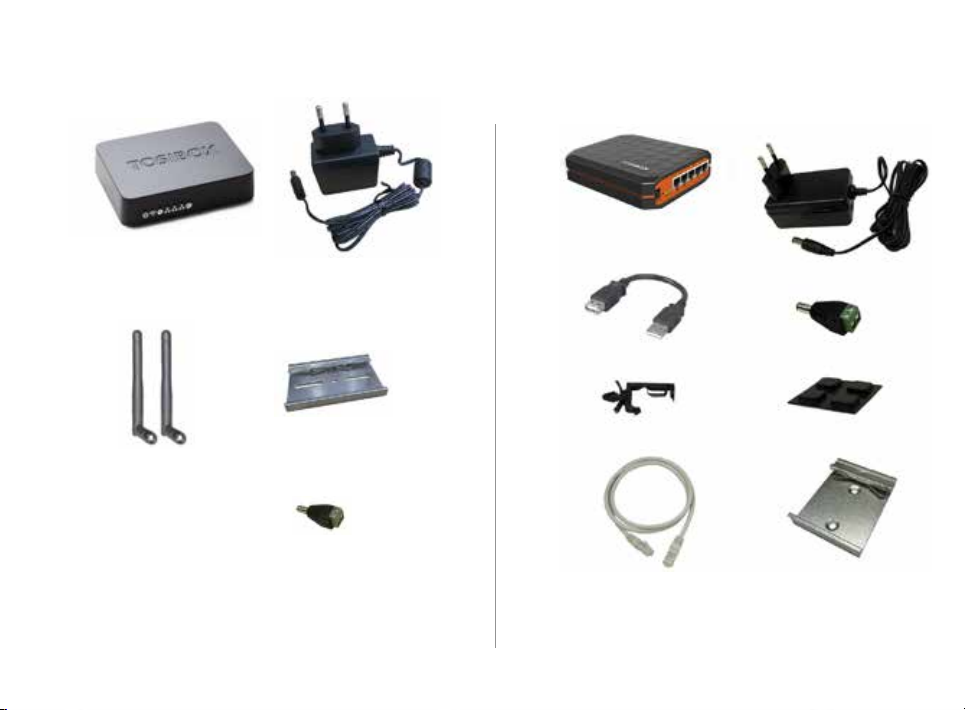
LOCK 100/150 CONTENT
TOSIBOX® Lock 100/150
AC Adapter*
10
LOCK 200 CONTENT
TOSIBOX® Lock 200
AC Adapter*
DIN Rail Bracket
Antennas (2)
DC Feed Plug
* AC Adapter model is subject to change according to the market area.
USB Cable
Cable Saddle
Ethernet Cable
* AC Adapter model is subject to change according to the market area.
DC Feed Plug
Rubber Feet
DIN Rail Bracket

11
LOCK 500/500i CONTENT LOCK 500 POWER SOURCE KIT CONTENT
TOSIBOX® Lock 500/500i
(LTE ports only in Lock 500i)
LTE Antennas*
(only Lock 500i)
Ethernet Cable
WiFi Antennas
AC Power Source*
DC Conversion Cable
Digital I/O
Connector
*) Antenna model is subject to change according to the market area.
Power
Connector
SIM Card
Slot Cover
*) AC Adapter model is subject to change according to the market area.
MODEL WIFI LTE POWER KIT WIFI ANT LTE ANT
TBL5iA x x x x
TBL5iAPS x x x x x
TBL5iB x x x x
TBL5iBPS x x x x x
TBL5iC x x x x
TBL5iCPS x x x x x
AC Plug Adapters

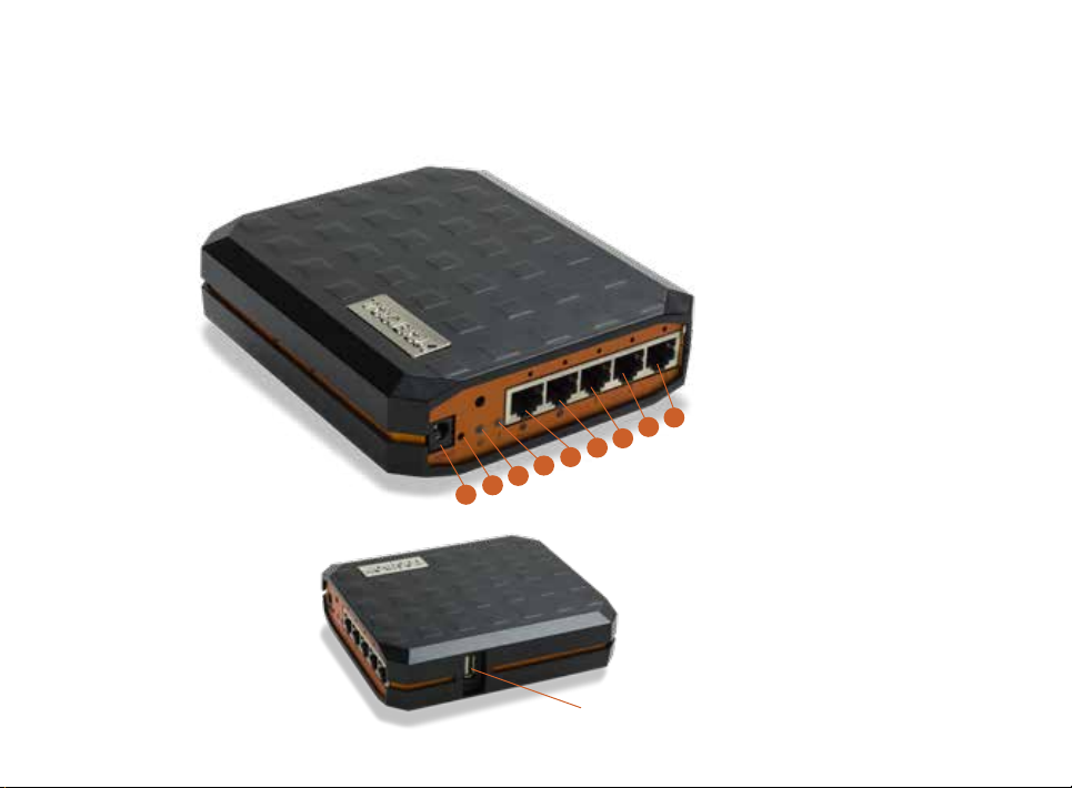
LOCK CONNECTIONS
12
LOCK 100/150
WLAN antenna ports
1. 2. 3. 4. 5. 6. 7. 8.
10. 11. 12. 13. 14. 15.
9.
1. USB Port for matching
and USB Modem
2. WAN Port
3. LAN1 Port
4. LAN2 Port
5. LAN3 Port
6. Service port
7. Reset button (not in use)
8. DC Power Input
Led indicators:
9. Power
10. WLAN
11. Service
12. LAN3
13. LAN2
14. LAN1
15. WAN
LOCK 200
13
1. DC Power Input
2. Reset button (not in use)
3. Power led indicator
9.
8.
7.
6.
5.
4.
3.
2.
1.
4. Info led indicator
5. WAN Port
6. Service Port
7. LAN1 Port
8. LAN2 Port
9. LAN3 Port
USB Port for matching and USB
Modem
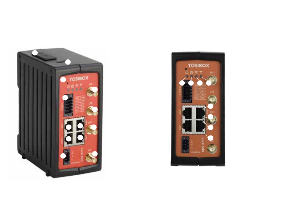
LOCK 500/500i
14
1.
2.
3.
4.
6.
5.
8.
7.
9.
* LAN3 Port can be configured as a Service Port
1. SIM card slot
2. USB Port for matching
and USB Modem
3. Reset button for Service
Port activation only
4. Digital I/O -Connection
10.
14.
15.
16.
17.
LED indicators:
14. Power
15. Internet
16. WiFi
17. LTE
Ethernet Connections:
11.
6. WAN Port
7. LAN3 Port*
5. LAN2 Port
12.
8. LAN1 Port
9. Power Connection
13.
10. WiFi Antenna Port 1
18.
19.
Ethernet Port Leds:
18. LAN2
20.
21.
19. WAN
20. LAN3
21. LAN1
11. LTE Antenna Port 2
(Lock 500i only)
12. WiFi Antenna Port 2
13. LTE Antenna Port 1
(Lock 500i only)

LOCK USER INTERFACE
15
Status bar shows
general information.
Locks and Keys
Green: Connected
Red: Disconnected
Remotely controlled
devices
Green: Connected
Red: Disconnected
Details of the remotely
controlled devices
Login using “admin”
user.
Password can be
found on the bottom of
the Lock

3. GETTING STARTED
THE FIRST DEPLOYMENT
1. Make sure the Lock is powered before
proceeding to matching the Key with the Lock.
Insert the Key into the USB port of the Lock.
When the LED on the Key turns off, the matching
is complete (approximately 10 seconds). Remove
the Key from the Lock. You can also match
additional Locks to the same Key.
2 - 3. Connect the Lock to your network according to
your use case. Remember to make sure that the
Lock has a working internet connection.
4. Connect the Key to your computer and install the
Key software. Follow the section ”Deploying the
Key”.
5. Secure TOSIBOX
be used for controlling and monitoring devices
remotely.
®
connection is now ready to
1.
3.
5.
16
2.
4.

4. TOSIBOX® LOCK INSTRUCTIONS
17
4.1.1 DEPLOYING LOCK IN “LOCK MODE”
HMI
®
TOSIBOX
Lock
Firewall
TOSIBOX
Mobile
Client
VPN tunnel
®
TOSIBOX
Key
®
through Internet
With its factory default settings, the Lock is connected to the
Internet via its WAN port or a USB modem which can be connected
to the USB port of the Lock. In this mode, the Lock creates its
own protected local network for the connected devices. In this
configuration, only devices that are connected to the Lock by cable
or via WLAN access point are accessible with the Key.
Note:
• See “USB Modem settings for the Lock” (page 18) to connect a USB modem to
the Lock’s USB port.
• If the Lock is connected to a DHCP enabled network via any of its LAN ports
(LAN1, LAN2 or LAN3) the Lock’s own LAN functionality can be restored by
resolving any DHCP conflicts by removing improper LAN connections to the
Lock.
CONNECTING NETWORK DEVICES TO THE LOCK
A) Connecting device(s) that use dynamic IP addresses (DHCP)
Devices with a DHCP client enabled will automatically connect to the
Lock. Plug the device(s) into the Lock’s LAN port(s) and go!
B) Connecting device(s) with Fixed IP addresses by configuring
the DEVICE to the LOCK:
PLC
Camera
PC
1. Before connecting device to Lock, connect to device per device
manufacturer’s instructions on your PC and assign a new static
IP address to device(s) from the Lock’s IP range printed on
the bottom label of the Lock. Do not add same IP address. We
recommend adding the next IP sequential address ABOVE the IP
address on the lock, and so forth for each additional device. (*Note:
Lock’s IP and netmask address can also be found in the service port
at Network > LAN)
2. Plug the device(s) into the Lock’s LAN port(s) and go!
C) Connecting device(s) with Fixed IP addresses by configuring
the LOCK to the DEVICE:
1. Get the device(s’) IP address(es) and netmask.
2. Connect your PC to the Lock’s service port and log in following the
step 1 on page 17 “Updating the Lock software”.
3. Go to Network->LAN and change the IP address in the “IPv4
address” field to the next IP address above the IP address of
the device (step 1). Also check that the “IPv4 netmask” field
corresponds to the netmask set on the device and change it if
necessary.
4. Plug the device(s) into the Lock’s LAN port(s) and go!
5. ADVANCED/ENTERPRISE USERS ONLY: Go to Network>LAN DHCP
SERVER and set the “Start” value so that it’s higher than all used
static addresses. Set the limit value to a suitable value so that it
covers the rest of the unused addresses in the LAN range. For
example, the range 192.168.5.50 – 192.168.5.254 contains 205
addresses so the “Start” value would be 50 and the “Limit”value
would be 205.

18
4.1.2 DEPLOYING LOCK IN “CLIENT MODE”
Client mode can be used for connecting the Lock to an existing
network (e.g. an office network). In this mode, the Lock joins the
network like any other device (e.g. a PC) and provides remote
users with access to other devices in the same network. The Lock
will obtain its address from the DHCP, so the local network needs
to have a working DHCP server that allocated IP addresses.
A) Connecting network devices in Client Mode
1. Log into the Lock’s web user interface as admin and open the LAN
settings by clicking Network > LAN.
2. Change the LAN interface protocol field to “DHCP Client”. Click the
“Switch Protocol” button and click “Save”.
3. Plug in a cable from the local network into one of the Lock’s LAN
ports and go!
PC
TOSIBOX
Key
VPN tunnel
®
through Internet
Note:
• Do not connect Internet to the Lock’s WAN Port or a USB modem to the USB
port. Doing so will automatically deactivate the Client Mode and revert the
Lock’s LAN settings back to factory defaults.
• Do no connect the controlled devices to any LAN port.
• The Lock will scan the entire LAN network for connected devices and will
grant device access to any user with a matched Key. Please keep this in
mind when considering network and information security.
• In cases where access rights need to be restricted, switch on MAC/IP
Filtering (under Advanced Settings) or set up the Lock in its factory default
configuration.
• In this mode, the Lock’s inbuilt firewall does not protect the devices in the
LAN network.
• Client Mode is deactivated from the Lock’s web user interface
PC
Server
Router
L
A
N
PC/Laptop
TOSIBOX
Lock
Printer
®

4.2 CONNECTING LOCKS
With TOSIBOX® Locks one can connect machines in separate
places so that the connection between them is permanently and
automatically on. One example is a real-time protected connection
between home and office. This is made with a Lock/Sub Lock
solution (see accompanying image Connecting Locks). To Lock 100
and Lock 150 can be connected to up to 10 Sub Locks, to Lock 200
and Lock 500 can be connected to up to 50 Sub Locks.
First match the Key to all the Locks to be connected as described
in section “Instructions for TOSIBOX
CONNECTING LOCKS
1. Insert a matched Key to the USB port of the computer.
2. Choose ”Devices” from the Key user menu and ”Connect Locks”
from the drop down menu.
3. Choose the Locks that you want to connect together and choose
”Next”.
4. Choose the Lock that you want to attach the Sub Locks. The other
Locks will be changed to Sub Lock operating mode.
5. Confirm the selection > Save > matching is ready.
Note: The connections will come into effect when the Locks have
access to the Internet.
The Sub Lock ends of the connection in the picture do not have
their own DHCP service. If the connection between the Lock and
the Sub Lock is interrupted, the network devices connected with
the Sub Lock can no longer connect to the Internet and each other.
®
Key and Lock setup”.
19
Lock
Sub Lock Sub Lock Sub Lock
Sublock Sublock Sublock
4.3 UPDATING THE LOCK SOFTWARE
1. a. Connect the computer to the service port of the Lock with
an ethernet cable. First check that you have access to the
Internet via the service port. Open an internet browser and type
http://172.17.17.17 into the address field to access the Lock user
interface. Do not type “www” before the “http://” in the address.
b. Alternatively you can also log in remotely. When the connection
between the Key and the Lock is active, double click the Lock symbol
in the Key user interface.
2. Log in using “admin” for the user ID. The default admin password is
visible on the bottom of the Lock.

20
3. Choose “Settings” > “Software update”. If there is a software
update available for the Lock, you can start the update by clicking
the “Start software update” button.
4. Wait until the update has been downloaded and installed. Do not
interrupt the power of the Lock during the software update
process. The update is complete when the software gives a notice
“Software updated successfully”.
Automatic software updates are activated as a default setting.
You can select the time when the automatic update of the released
software is allowed. You can deactivate the automatic software
update from the Lock user interface.
Choose “Settings” > “Software update” > uncheck the box “Autoupdate enabled”.
4.4 USB MODEM SETTINGS FOR THE LOCK
You can connect the Lock to the Internet with a USB Modem. For
information on supported modems go to:
http://www.tosibox.com/support.
1. Log in as admin user, select “Network” > “USB Modem”.
2. Either use the Automatic APN setting or fill in the APN and if
necessary the PIN field according to the SIM card settings. For APN
settings information, please contact your mobile operator.
3. Confirm the selection > Save.
4. Connect a Tosibox supported USB Modem to the USB port of the
Lock.
4.5 INTERNAL MODEM SETTINGS FOR LOCK 500I
You can connect the Lock to the Internet with an internal Modem.
Before inserting or removing the SIM card(s), disconnect the Lock
power supply.
1. Log in as admin user, select “Network” > “Internal Modem”
2. Either use the Automatic APN setting or fill in the APN and if necessary
the PIN field according to the SIM card settings. For APN settings
information, please contact your mobile operator.
3. Confirm the selection > Save.
4.6 WLAN SETTINGS FOR LOCK 100, LOCK 150
AND LOCK 500
On Lock 100, Lock 150 and Lock 500 you can configure the WLAN as
Client (providing Internet access for the Lock) or as Access Point
(providing access to Lock LAN and Internet for wireless devices). For
detailed set-up instructions visit http://www.tosibox.com/support.
4.7 KEY CONNECTION SETTINGS FOR THE LOCK
You can change the Key connection type from Layer 3 -routed
(default) to Layer 2 -bridged (“Connection type” > “Layer 2-bridged”).
On Layer 2 connections you can allow connections from Lock to Key.
Log into the Lock as admin, select “Settings” > “Keys and Locks” >
remove selection “Deny access towards client”
For more details on Layer 2 and Layer 3 connections visit
http://www.tosibox.com/support.

21
4.8 ADVANCED SETTINGS FOR THE LOCK
On the Advanced settings page you can configure LAN and Internet
access restrictions and security related settings.
1. Log in as admin
2. Choose “Settings” > “Advanced settings”
3. Confirm changes > Save
4.9 INTERNET CONNECTION PRIORITIES
Several alternative Internet connections can be used by the Lock:
1. WAN
2. USB modem
3. WLAN (Lock 100, Lock 150 and Lock 500 only)
4. Internal modem (Lock 500i only)
One of the available connections can be selected as a main
connection and the other connections can be set as backup
connections. In the event that the main connection is interrupted,
the connection is automatically shifted to preselected backup
connections according to the priority setting (eg. WAN port > USB
Modem). The connection is switched back to the main connection
once it is available again.
4.10 POE
(LOCK 200 ONLY)
The “PoE out” port supports PoE output, with auto detection
feature. This means you can connect laptops and other non-PoE
devices without damaging them. The PoE on “PoE out” outputs
approximately 2V below input voltage and supports up to 0.58A (So
e.g. 24V PSU will provide 22V/0.58A output to the “PoE out” port).
The device accepts powering from the power jack or from the “PoE
in” port (passive PoE)
1. DC power jack (5.5mm outside and 2mm inside diameter, female
center pin positive) accepts 8-27V DC +/-10%
2. The “PoE in” port accepts passive Power over Ethernet 8-27V DC
+/-10%
Under maximum load, the power consumption of this device is 7W.
4.11 SERVICE PORT
On Lock 100, Lock 150 and Lock 200 a dedicated Service Port is
available. On Lock 500, LAN3 port can be configured as Service
port by pressing the reset button for 3 seconds when there is
no cable in LAN3. When completed, the Internet status LED will
blink for three seconds. Lock Management Interface can then be
accessed by entering http://172.17.17.17 on the address bar of
your browser. Assigning the port back to LAN range can be done
following the same procedure or by restarting the device.

22
4.12 MOUNTING INSTRUCTIONS
LOCK 100/150 QUICK INSTALLATION TO DIN RAIL
The bottom of the Lock has integrated hooks that allow a quick
installation to DIN rail with the LAN/WAN ports facing upwards.
LOCK 100/150 SECURE INSTALLATION TO DIN RAIL
For environment where a more robust installation method is
needed or another installation orientation is wanted, the Lock
can be installed to DIN rail with the clip and screws included in
Lock 100/150 with DIN rail bracket
the sales package. There are M4 threaded mounting holes on the
bottom of the equipment. The screws shall be placed through the
bottom sticker which has the hole locations indicated. Use only the
screws included in the sales package. Using longer screws pose
a risk of damaging the device internal electronics. More versatile
installation options to DIN rail, such as angle brackets are available
from an authorized TOSIBOX® reseller as an accessory.
LOCK 100/150 WALL MOUNTING
The bottom of the Lock has two keyhole shaped openings that allow
the Lock to be installed on the wall with countersunk screws.
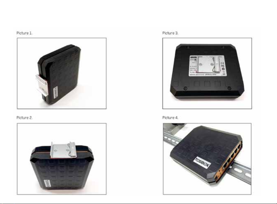
LOCK 200 INSTALLATION TO DIN RAIL
The Lock can be installed to DIN rail with the clip and screws
included in the sales package. There are M3 threaded mounting
holes on three sides of the equipment. For attachment on either of
the narrow sides, the screws with length of 10 mm shall be used.
For attachment on the bottom of the Lock, the screws with length
of 6mm shall be used. The screws shall be placed through the
bottom sticker which has the hole locations indicated.
See pictures 1 - 4 for the mounting options.
23

24
LOCK 200 USING THE RUBBER FEET
Rubber feet included in the sales package can be installed in the
bottom of the Lock for more convenient installation horizontally
e.g. on a table.
See picture 5 and 6 for the mounting.
Picture 5.
Picture 6.
LOCK 500 INSTALLATION ON THE TABLE
The Lock can be placed standing vertically on its rubber feet. There
are vent holes on both sides of the device, designed to provide
cooling air passing through the device. Allow enough free space,
minimum of 25mm around the Lock to ensure the free flow of
cooling air.
Make sure there is no risk of the device falling aside as this
would block the cooling air flow through the vent holes. Have all
the cables secured in such a way that they cannot make the Lock
fall aside and routed as far away from the antennas as possible.
Position the antennas in orthogonal pattern, i.e. in such a way that
they form 90 degrees angle between each other.
Observe the gender of the antenna connectors to make sure each
antenna is fitted into the correct antenna port. To achieve the
maximum radio performance, follow the antenna pattern shown in
Picture 7.
Avoid installing the Lock close to other high-power radio
transmitters as they may affect the performance of the Lock. Also
avoid installing the Lock close to any sensitive devices that may be
affected by the antenna signals emitted by the radio transmitter
of the Lock. In case of unwanted disturbance, relocate the cables
and/or the Lock in a place where the devices do not disturb each
other.

25
LOCK 500 INSTALLATION TO DIN RAIL
The Lock can be installed to DIN rail by using the integrated DIN rail
bracket located in the backside of the device. Follow the sequence
shown in picture 7.
Removal is the reverse of installation. There are vent holes on both
sides of the device, designed to provide cooling air passing thru
the device. Allow enough free space, minimum of 25mm around
the Lock to ensure the free flow of cooling air. Route and secure
all cables as far away from the antennas as possible. Position the
antennas in orthogonal pattern, i.e. in such a way that they form
90 degrees angle between each other. Observe the gender of the
antenna connectors to make sure each antenna is fitted into the
correct antenna port.
To achieve the maximum radio performance, follow the
antenna pattern shown in Picture 7. Installing the Lock inside
of metal cabinet may result in the degradation or loss of radio
performance. In such case have the antennas installed outside of
the cabinet using coaxial RF extension cables, available at your
local specialized dealer or service technician.
Avoid installing the Lock close to other high-power radio
transmitters as they may affect the performance of the Lock. Also
avoid installing the Lock close to any sensitive devices that may be
affected by the antenna signals emitted by the radio transmitter
of the Lock. In case of unwanted disturbance, relocate the cables
and/or the Lock in a place where the devices do not disturb each
other.
Picture 7.
1. Place the DIN-rail
bracket slider under
the lower edge of the
DIN rail.
Picture 8. Lock 500i installed
to DIN rail. See the antenna
directions.
2. Push the Lock
upwards until the
slider travel is in
the end
3. Push the upper
edge of Lock parallel
to the wall
4. Slide the Lock
down and check that
the DIN rail bracket
has a firm grip of the
DIN rail

26
4.13 INPUT POWERING OPTIONS
LOCK 100/150
Use the AC adapter included in the sales package. Alternatively,
in case the operating voltage of 8-30V DC (absolute value) is
available from an external power source, a DC input plug included
in the sales package can be used. Connect the stripped wires by
tightening the screws with a flat blade screwdriver. Follow the
polarity marking in the plug.
LOCK 200
Use the AC adapter included in the sales package. Alternatively, in
case the operating voltage of 8-27V DC +/-10% is available from
an external power source, a DC input plug included in the sales
package can be used. Connect the stripped wires by tightening the
screws with a flat blade screwdriver. Follow the polarity marking
in the plug.
To secure the input power cable from being accidentally pulled
away from the power input jack, the use of the cable saddle is
recommended. The cable saddle is included in the sales package
and it is locked in place by inserting it into the 4mm diameter hole
in the front panel. Loop the power cable around the frame and
snap the jaw closed.

27
LOCK 500
A power source with voltage of 12-48V DC +/-20% is required
to operate the Lock. The power input port is equipped with a
removable plug-in connector included in the sales package.
Remove the connector if needed and connect the stripped power
wires by tightening the wire connector screws with a flat blade
screwdriver.
A device frame connection is available at the power input
port. It is recommended to wire this connection to the installation
cabinet protective earth potential with as short cable as possible.
This will enhance the immunity of the equipment against conducted
and radiated RF disturbance, as well as against electrical
transients that may be propagated by the ethernet cables. Use
+ and - terminals to power the device. Follow the polarity and
grounding symbols in the front panel.
Make sure the connector is completely plugged in and secure the
connector into the Lock frame by tightening the locking screws
with a flat blade screwdriver. The wires with a cross-section of up
2
to 1.5mm
length of the conductor is 6 mm.
The Lock is equipped with a 2 Amp internal fuse. In case of a device
malfunction, the fuse is blown to protect the power circuitry. The
fuse cannot be replaced by the user. In case of a blown internal
fuse, do not open the device. Instead, contact your local Tosibox
distributor for service.
(AWG 16) can be used with the connector. The stripping
LOCK 500*PS
In addition to the powering options for Lock 500, an AC adapter
included in the Lock500*PS-version sales package may be used.
The AC adapter is supplied with interchangeable plugs that makes
it possible to connect to different electrical outlets. Select and
fit the plug that complies with your local requirements. The AC
adapter DC output connector is coaxial. Therefore, a conversion
cable is necessary to convert from coaxial DC connector to
stripped wires required by the Lock power input connector. The
conversion cable is included in the Lock500*PS-version sales
package. Follow the same procedure as with Lock 500 powering
options.

28
4.14 LOCK 500 - DIGITAL IN/OUT PORT WITH
24V DC OUT
The Digital I/O port is equipped with a removable plug-in connector
included in the TOSIBOX Lock 500 sales package. Remove the
connector if needed and in case of a solid wire simply insert
the stripped signal wire to the correct port opening. In case a
flexible wire is used, press the release button with a flat blade
screwdriver to open the locking springs and insert the wire.
Follow the signal symbols in the front panel and connect all needed
signals. Make sure the connector is completely plugged in and
secure the connector into the Lock frame by tightening the locking
screws with a flat blade screwdriver. The wires with a crosssection of up to 1.5mm2 (AWG 16) can be used with the connector.
The stripping length of the conductor is 10mm. The wire is
released from the connector by pushing the corresponding release
button with a flat blade screwdriver.
4.15 LOCK 500 - SOFTWARE CONFIGURABLE I/O
The Digital I/O state information and configuration can be
accessed from Settings -> Digital I/O menu. For signal physical
properties, please refer to section I/O specifications at the end of
this manual.
Input port roles can be selected from:
Not selected – no action based on port state
Allow Internet connection – when port voltage is set high, Lock
allows Internet connections. When port voltage is set low, there
is no Internet access and the Lock visibility is “offline” for all Keys
matched with it.
Prevent Internet connection – when port is set high, Lock
prevents Internet connection and the Lock visibility is “offline” for
all Keys matched with it. When port voltage is low, Internet access
is allowed.
Allow VPN connections – when port voltage is set high, Lock allows
incoming VPN connections from matched Keys. When port voltage
is low, VPN connections are not allowed and the Lock visibility is
“offline” for all Keys matched with it.
Prevent VPN connections – when port is set high, VPN connections
are not allowed and the Lock visibility is “offline” for all Keys
matched with it. When port voltage is low, Lock allows incoming
VPN connections from matched Keys.

Output port roles can be selected from:
Not selected – no action based on port state
Internet connection OK – when Lock detects Internet connection
to be OK, the port voltage is set high. If the Internet connection is
not OK, the port voltage is set low.
Internet connection failed - when Lock detects there is no Internet
connection, the port voltage is set high. If the Internet connection
is OK, the port voltage is set low.
29
VPN connection active – when Lock detects active VPN
connection(s) from matched Keys, the port voltage is set high.
When there are no active VPN connections, the port voltage is set
low.
VPN connection inactive – When there are no active VPN
connections the port voltage is set high. When Lock detects active
VPN connection(s) from matched Keys, the port voltage is set low.

30
4.16 LOCK 500 - DIGITAL I/O SMS ALERT
In order for the SMS alert feature to work, make sure to use a SIM
card that supports sending SMS messages.
SMS alert feature can be activated on Digital I/O settings by
selecting “Send SMS” for “Input port 1 role” and/or “Input port
2 role”. After this, more settings for the SMS alert feature will
become visible.
The following settings need to be defined for input port 1 or input
port 2 or both:
Input port ≤X≥ SMS action
Select the trigger (high / low) for SMS sending: “Send message when
input ≤X≥ is high” or ”Send message when input ≤X≥ is low”
Input port ≤X≥ SMS message
Define the message to be sent. Concatenated SMS is not supported
so the maximum length of a message is 160 characters (western
alphabet). If using non-western alphabet, the limit is 70 characters.
Input port ≤X≥ SMS phone numbers
Enter phone number(s) to send the message to. Only one number per
input field is allowed. More phone numbers can be added by adding a
new input field.
Input port ≤X≥ SMS send limit
Determines how many messages per minute will be sent. “0” stands
for no limit. Use this feature when the I/O may switch high-low several
times and you do not want to send SMS for each state change.
Any message sent will be sent to all numbers defined in “Input port ≤X≥
SMS phone numbers”
Input port ≤X≥ SMS target modem
Currently only internal modem is supported. In case there are two
SIMs inserted, the SMS will be sent from the active SIM at the time
of the alarm.
Both I/O ports have SMS settings independent of each other.

Sending an SMS will happen in 1-10 seconds of the trigger. In case
the SIM subscription does not support sending SMS, the messages
will not be sent.
Once the SMS has been sent by the Lock 500, the time to get it
delivered to the destination is dependent on the Operator used.
Some subscriptions need the Message Service Center number
defined to be able to send SMS messages. This can be set in
“Internal Modem “ settings where ”SMS center number” can be
defined. The number should be defined in international format (e.g.
“+358…”
Note that the setting can be defined separately for both SIM slots.
31

5. TOSIBOX® KEY INSTRUCTIONS
32
5.1 TAKING MASTER KEY INTO USE
1. Insert the matched Key into the USB port of your computer. You
should notice an auto play window open up on your desktop. If not,
double click the executable file located in the Key’s folder (Setup_
Tosibox.exe). If your computer asks whether you want to allow
Tosibox to make changes to your computer click yes.
2. The Key software will ask for a password that you can enter if you
wish (recommended). By entering a password, you can prevent the
unauthorized use of the Key. Store the password safely. Also pay
attention to PUK code instructions on section 6.5.
3. The Key software opens up a window that shows the Locks that
have been matched to the Key. Connect the Key with the wanted
Lock by clicking the Lock’s “Connect” icon.
4. The Key info dialogue shows the status of the connection between
the Key and Lock.
The Key is now ready to be used
The Lock symbol displays a different colour according to the
operating status of the Lock:
• Red = The Lock is not connected to the Internet.
• Yellow = The Lock is connected to the Internet, but the Key doesn’t
have a remote connection to the Lock.
• Green = The Lock is connected to the Internet and the Key has a
remote connection to the Lock.
The Key symbol located in the computer’s task bar displays
different colours according to the operating status of the Key:
• Red = The Lock is not connected to the Internet.
• Yellow = The Key is connected to the Internet, but not to any found
Locks.
• Green = The Lock is connected to the Internet and the Key has a
remote connection to the Lock.
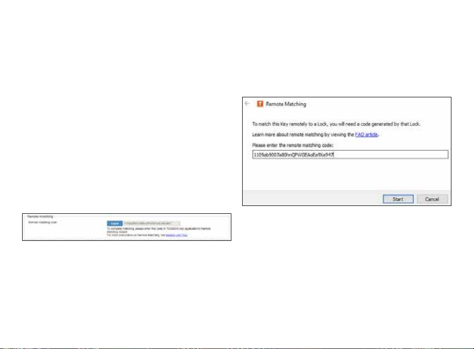
REMOTE MATCHING
Remote Matching is an alternative way to match the first master
Key to a new Lock, Central Lock, or Virtual Central Lock. In Remote
Matching, the Key does not have to be physically connected to a
Lock, but it uses a unique, cryptographic code instead. This can
be useful e.g. if the Lock needs to be reset and the master Key is
not available in the same place. With Virtual Central Lock, remote
matching is the only way to match it with a master Key.
The process is initiated by generating the remote matching code
on the Lock that shall be matched, which enables remote matching
on the Lock with that code only. Then, the remote matching wizard
is opened on the master Key software and the code is entered
there. This completes the process and the devices will establish
a trust relationship over the Internet. The Lock appears on the
master Key similarly as after physical matching.
Note: make sure to keep the code safe when transferring it to the
master Key as anybody who knows the code can match the Lock
and connect to it. If the code gets lost, deactivate remote matching
on the Lock’s web user interface and start it again by generating
a new code.
33
Currently Remote Matching is supported on following Lock
products:
• Lock 500/Lock 500i
• Lock 150
• Virtual Central Lock with SW 2.2.0 or later
• Central Lock with SW 2.3.0 or later
• Lock 100 and Lock 200 with SW 3.3.0 or later
• You will also need TOSIBOX
®
Key SW v2.15.0 or later to complete the
matching process. Both the Lock and the Key need to be connected
to the Internet for the feature to work.
Required Steps to Perform Remote Matching
1. Log in as admin on Lock or (Virtual) Central Lock
2. Go to Settings > Keys & Locks click Generate button under Remote
Matching title
3. Start Key SW on a PC/Mac
4. Open Devices > Remote Matching
5. Enter the code in the wizard and click Start
If both devices are online, the process completes after a few
seconds and the Lock is now matched with the Key.
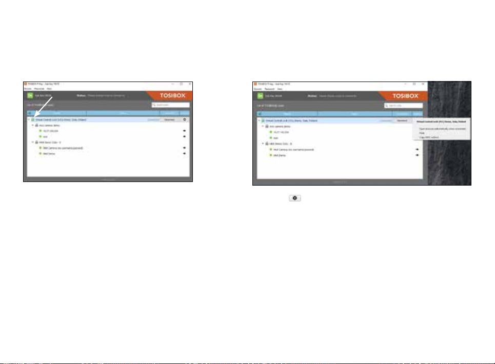
5.2 RENAMING AND USING DEVICES
34
This is the start window for the Key user interface.
You can open the Lock user interface by double
clicking the Lock icon on the left side of the window.
By clicking an extra menu opens.
1. Click “Open browser automatically when connected” to have the
Lock user interface launch automatically when the Key connects to
the Lock.
2. Selecting “Show all details” allows you to view all the details of the
connected device.
3. Click “Rename” to rename the selected Lock. The Lock names are
global so a Lock’s name change will be reflected on all locks and
Keys. Only Master and Back-up Keys can rename Locks.
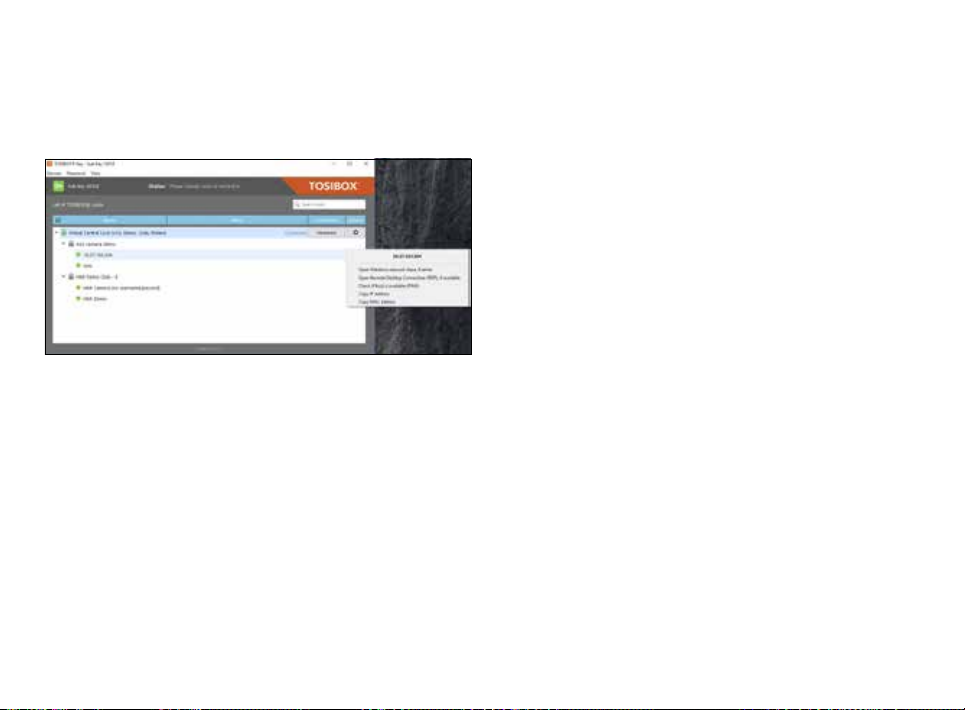
1. You can open the browser user interface of the controlled device
in “Open with browser (http)”.
2. You can connect to network sharing in “Open windows network
share”.
3. You can open the remote desktop connection in “Open Remote
Desktop Connection (RDP), if available”.
4. You can check the functionality of the controlled device with PING
command in “Check if host available (PING)”.
35

36
5.3 ADDING EXTRA KEYS
Additional Keys can be matched with a Lock.
1. Insert a previously matched Key into the USB port of your
computer.
2. Insert a new Key to another USB port of the computer.
3. Wait until ”New Key” window opens.
4. If you are adding a Sub Key, follow the steps 1-4 ADDING SUB KEY.
If you are adding a Backup Key, follow the steps 1-4 ADDING
BACKUP KEY.
ADDING TOSIBOX® SOFTKEY
To activate SoftKey on a PC or Mac, you will need:
1. SoftKey license for the master Key – please contact our sales to
purchase one
2. Key SW v3.0.0 or later both on the master Key and the client
computer – see download instructions here
Also, to connect to Locks with SoftKey, the software on the
Lock needs to support SoftKeys. SoftKey is supported by these
versions:
1. Lock 100 and Lock 200: SW v3.3.0 onwards
2. Central Lock and Virtual Central Lock: SW v2.3.0 onwards
3. Lock 500 / Lock 500i: all versions
4. Lock 150: all versions
ACTIVATION
The activation process has five steps as outlined below:
1. On master Key: generate activation code:
Go to Devices > Manage Keys > Add Key, and add a new Key of type
“SoftKey” and give it a name.
2. An activation code will be generated, send it over to the end user
who shall activate and use the SoftKey client.

37
3. On client computer: activate SoftKey: Make sure TOSIBOX® Key
software v3.0.0 or later is installed on the PC. Start the software.
Activate the SoftKey by choosing Devices > Activate SoftKey and
enter the activation code.
4. On Master Key: Confirm SoftKey. Confirm the activation from the
pop-up dialog.
5. Define access rights for the new SoftKey by following the wizard.
The SoftKey is now ready to be used and can connect to the Locks
where access was granted in step 5.

ADDING SUB KEY
38
1. When a new Key is
turned into a Sub Key,
choose ”Sub Key”,
provide a descriptive
name for it, and click
”Next”. A Sub Key is able
to connect to chosen
Locks but it has no
rights to create new
Keys.
3. Confirm the selection
by pressing ”Save”.
Matching of the extra
Key is now complete.
2. Select the Lock(s)/Sub
Lock(s) to which you
want to grant access
for the extra Key and
choose ”Next”.
4. The extra Keys can be removed in the Lock user
interface by clicking Settings > Keys and Locks
(admin only).

ADDING BACKUP KEY
39
1. Choose ”Backup Key”
and press ”Next”.
All Keys and Locks
are automatically
2. Confirm by pressing
”Save”.
3. The Backup Key is now
synchronized between
the Backup Keys.
created. Press ”Close” button to exit the feature.
4. The Backup Keys can be managed later in the Key user interface
under ”Manage Keys”. Important: This feature creates a Backup Key
with equal user rights. Later, when the new locations are deployed
by the other Key, the access rights are automatically copied to both
Keys.

EXTRA KEY USE CASE
40
Key Subkey
Sub Key

41
5.4 REMOTE MATCHING OF EXTRA KEYS
This feature is only available for Keys that have already been
matched locally.
1. Insert the Key into the USB port of the computer and wait for the
2. Choose ”Manage Keys” from the “Devices” menu in the user
3. Choose the extra Keys to which you want to add new Locks and
4. Choose the Locks to which you want to add to the extra Keys and
5. A list of targeted Locks is displayed. Confirm the choises and click
6. Matching of the extra Keys is now complete. Press “Finish” button
®
TOSIBOX
Key application to start.
interface and open the “Sub Keys” tab.
press the ”Match...” button.
press the ”Next” button.
“Save”.
to exit the wizard.
5.5 PUK CODE FOR THE KEY
1. In the event that a wrong Key password has been entered six
consecutive times, the Key will be locked. To unlock the Key a
personal unlocking code, PUK is needed. The PUK code is delivered
with the Key. Store it safely.
2. Go to the ”Password” menu in the Key software and choose
”Change password using PUK code...”.
3. Enter the PUK code into the ”PUK-code” field.
4. Enter a new password into the ”New password” field.
5. Confirm your password by typing it once more into the “New
password (again)” field.
6. Choose ”OK”.
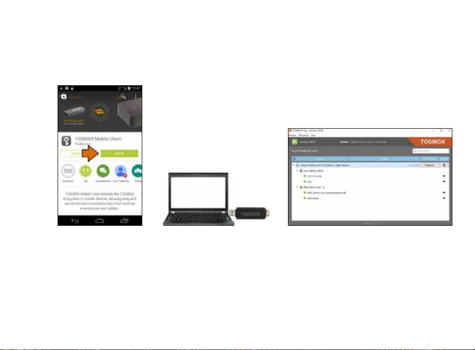
6. TOSIBOX® MOBILE CLIENT INSTALLATION
6.1 MOBILE CLIENT FOR ANDROID DEVICES
42
1. Download and install the
TOSIBOX® Mobile Client
from the Google Play
store.
2. Open the TOSIBOX® Key software
by plugging a matched Key into
the USB port of your computer.
3. Go to the software menu and select
Devices > Manage Keys.

43
4. Select the mobile clients tab and click
Add new...
5. Enter the name of your mobile device and
click Next.
6. Select the Locks that you would like to
access through your mobile device and
click Next.

44
7. Open the TOSIBOX®
Mobile Client on your
device.
8. Tap the screen to start
matching.
9. Scan the QR code displayed on your
computer or enter the matching code
where prompted on your device.
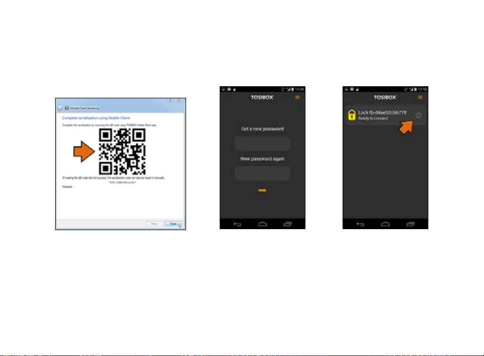
45
10. Click Finish once the matching is
complete.
11. Create a password for
the mobile client.
12. Connect to a Lock by
selecting its on/off icon.
46
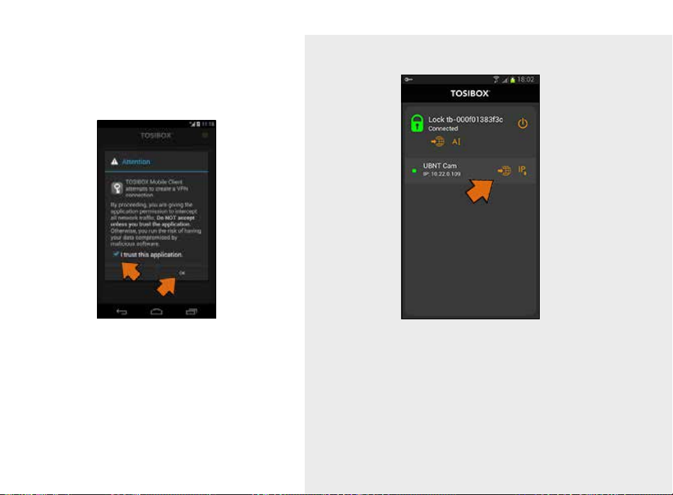
13. Check the I trust this
application dialogue box
and click OK.
14. Now your mobile client is matched and can connect to the selected Locks
and devices connected to them.
You can open network devices through your web browser (if available)
by clicking the the appropriate globe icon. Note: If your network device
does not have a web interface (HTTP / HTTPS), you can use a third party
application to make the connection. You can find third party applications
from the Google Play store. You can copy the network device IP address to
the device’s clipboard by clicking the IP button. Doing so will allow you to
paste the IP address to a third party application.
6.2 MOBILE CLIENT FOR IPHONES AND IPADS
47
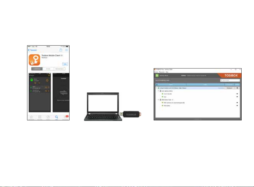
1. Download and install the
TOSIBOX® Mobile Client
from the App Store.
2. Open the TOSIBOX® Key software
by plugging a matched Key into
the USB port of your computer.
3. Go the software menu and select Devices
> Manage Keys.

48
4. Select the Mobile Clients tab and click
Add new...
5. Enter the name of your mobile device and
click Next.
6. Select the Locks that you would like to
access through your mobile device and
click Next.

49
iOS
7. Open the TOSIBOX®
Mobile Client on your
device.
iOS
8. Tap the screen to start
matching.
9. Scan the QR code displayed on your
computer or enter the matching code
where prompted on your device.

50
10. Click Finish once the the matching is
complete.
11. Create a password for
the mobile client.
12. Connect to a Lock by
selecting its on/off icon.
51
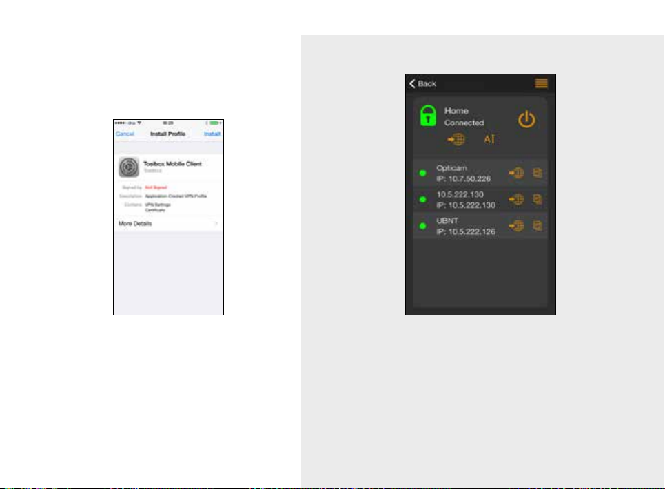
13. On the first time when
connecting to a Lock, the
user needs to authorize
the installation of the
VPN profile by entering
the device passcode.
14. Now your mobile client is matched and can connect to the selected Locks and
devices connected to them.
You can open network devices through your web browser (if available)
by clicking the the appropriate globe icon. Note: If your network device
does not have a web interface (HTTP / HTTPS), you can use a third party
application to make the connection. You can find third party applications
from the App Store. You can copy the network device IP address to the
device’s clipboard by clicking the IP button. Doing so will allow you to paste
the IP address to a third party application.

7. TROUBLESHOOTING
The TOSIBOX® Key software cannot be installed:
• Check whether your computer has an operating system supported
by TOSIBOX®: Windows 10, Windows 8/8.1 (32/64 bit), Windows 7
(32/64 bit), Windows Vista (32/64 bit), Windows XP (SP3), Windows
Server 2003, Windows Server 2008, Mac OS X 10.9 Mavericks or
more recent (Intel 64-bit)
• Restart the computer and plug in the Key.
The Key’s connection window does not show the connections:
• The computer is not connected to the Internet.
• The Key is not matched with the Lock.
• The Lock does not have an internet connection or is not connected
to the AC adapter.
The Lock connection in the window remains yellow:
• The Key has found a Lock, but VPN has not yet been established.
Device connections or the Lock connection in the window remains
red:
• Make sure the controlled devices are connected to the Lock.
• If connected wirelessly (Lock 100, Lock 150, Lock 500), use the
ethernet service port to log in to the Lock. Check that the wireless
connection is enabled and that the Lock and the controlled device
have the same password and encryption settings.
• Make sure the controlled device has a DHCP-service. If not, add the
device in the device list of the Lock and specify the IP address of the
device .
Visit http://www.tosibox.com/support for more instructions.
52
7. DÉPANNAGE
Le logiciel pour la TOSIBOX® Key ne peut être installé
• Vérifiez que votre ordinateur dispose d’un système d’exploitation pris en
charge par TOSIBOX®: Windows 10, Windows 8 / 8.1 (32/64 bits), Windows
7 (32/64 bits), Windows Vista (32/64 bits), Windows XP (SP3) , Windows
Server 2003, Windows Server 2008, Mavericks Mac OS X 10.9 ou plus
récent (Intel 64 bits)
Redémarrez l’ordinateur et branchez la Key.
La fenêtre de connexion de la Key ne montre pas les connexions :
• L’ordinateur n’est pas connecté à Internet.
• La Key n’est pas associée au Lock.
• Le Lock ne dispose pas d’une connexion Internet ou n’est pas sous tension.
La connexion du Lock dans la fenêtre reste jaune :
• La Key a trouvé un Lock, mais le VPN n’a pas encore été établi.
Les connexions au périphérique ou la connexion de LOCK dans la fenêtre
reste rouge :
• Assurez-vous que les appareils contrôlés sont connectés au Lock.
• Si vous êtes connecté via un réseau sans fil (Lock 100, Lock 150, Lock 500),
connectez-vous au Lock par le port de service Ethernet. Vérifiez que la
connexion sans fil est activée et que le Lock utilise le bon mot de passe et les
mêmes paramètres de cryptage de l’appareil supervisant le réseau sans fil.
Assurez-vous que l’appareil supervisant le réseau sans fil dispose d’un
service DHCP. Sinon, ajoutez le LOCK à la liste des périphériques et
spécifiez son adresse IP.
Pour plus d’instructions, visitez : http://www.tosibox.com/support

53
8. MAINTENANCE INSTRUCTIONS
TOSIBOX® devices should be treated with care. By observing the
following instructions you can enjoy the maximum performance of
the devices and ensure full warranty coverage.
• Keep the devices dry. Protect the devices from precipitation, moisture
and liquids as they can cause corrosion to electronic circuits. The
devices are intended for indoor use only. Do not use them in wet
environment or outdoors.
• Protect the devices from dirt and dust. When necessary, clean
the devices with a soft, dry cloth. Do not use chemicals, solvents,
detergents or pressurized air.
• Protect the devices from heat. High temperatures can damage plastic
parts and shorten the life of the electronics.
• Protect the devices from cold. Low temperatures can make them
more susceptible to breakage. Let the device’s temperature stabilize
properly before deploying them into the network..
• Protect the devices from mechanical shocks. Do not shake, knock or
drop the devices.
• Do not paint the devices.
• Do not cover the devices or install them on top of each other. This can
cause overheating. Allow enough free space around the devices to
ensure the free flow of cooling air.
• Do not open the devices. There are no serviceable parts inside the
devices. If the devices malfunction or need servicing, contact an
authorized service facility.
• After the service life of the devices is over, do not
throw them into domestic waste. Instead, take them
to an authorized waste electronics collection facility.
8. CONSIGNES D’ENTRETIEN
Les équipements TOSIBOX® doivent être traités avec précaution. En observant les
instructions suivantes, vous profiterez de leurs performances maximales et aurez
l’assurance d’avoir une garantie optimale.
• Gardez les appareils au sec. Pour éviter des risques de corrosion des circuits
électroniques, protégez les équipements des précipitations, de l’humidité et des
liquides. Les appareils sont conçus pour une utilisation en intérieur uniquement.
Ne les utilisez pas dans un environnement humide ou à l’extérieur.
• Protégez les appareils de la saleté et de la poussière. Si nécessaire, nettoyez les
appareils avec un chiffon doux et sec. N’utilisez pas de produits chimiques, de
solvants, de détergents ou d’air comprimé.
• Protégez les appareils de la chaleur. Les températures élevées peuvent
endommager les parties en plastique et raccourcir la durée de vie des
composants électroniques.
• Protégez les appareils du froid. Les basses températures peuvent les
rendre plus sensibles à la casse. Avant leur installation, laissez-les revenir à
température ambiante.
• Protégez les appareils des chocs mécaniques. Ne les secouez pas, ne les
frappez pas et ne les laissez pas tomber les appareils.
• Ne peignez pas les appareils.
• Ne couvrez pas les appareils et ne les empilez pas les uns sur les autres sous
peine de provoquer une surchauffe. Assurez-vous d’assez d’espace libre autour
des appareils pour leur refroidissement par libre circulation d’air.
• N’ouvrez pas les appareils. Aucune réparation ne peut être effectuée par vous-
même. Si les équipements ne fonctionnent pas correctement ou nécessitent une
réparation, contactez un centre de réparation agréé.
• Après leurs utilisations, ne les jetez pas mais ramenez-les
dans un centre de collecte de déchets électroniques.

9. TECHNICAL DATA
TOSIBOX® LOCK 100
Ports
• 1x USB 2.0, type A, 500 mA maximum load allowed
• 1 x RJ-45 WAN conn., 10/100 Mb/s, auto-negotiation (MDI / MDI-X)
• 3 x RJ-45 LAN conn., 10/100 Mb/s, auto-negotiation (MDI / MDI-X)
• 1 x RJ-45 Service conn., 10/100 Mb/s, auto-negotiation (MDI / MDI-X)
WAN connection features
• Independent of operating systems
• Works in all Internet connections (operator independent)
• Firewall friendly
• Works with dynamic, static and private IP addresses
• Built-in firewall, NAT
• Up to 10 concurrent VPN connections
• VPN throughput up to 6 Mb/s (BF-CBC 128 bit)
Physical properties
• 132 mm x 99 mm x 35.5 mm / 5.2” x 3.9”x 1.4” (L x W x H)
• Weight 365 g / 1.31 lbs (net weight article)
• Operating temperature -25 °C … +70 °C / -13 °F … 158 °F
• Oparating humidity 20 - 80% RH, non condensing
• Storage temperature -40 °C … +70 °C / -40 °F … 158 °F
• Cast aluminium casing
• IP protection class: IP20
• Maximum operating altitude 2000 m / 6562 ft
• Overvoltage category I
54
USB modem options
• TB4GM2EU, TB4GM2AU, for 3rd party options,
please see: http://www.tosibox.com/support
WLAN
• IEEE 802.11 b/g/n, max. 150 Mbps
• WEP, WPA-PSK, WPA2-PSK, WPA-PSK/WPA2-PSK Mixed, WPA-EAP,
WPA2-EAP TKIP/AES encryption
• Frequency 2.412 – 2.462 GHz, 11 channels
• Output power 20 dBm max
Powering requirements
• 8-30V DC (absolute value), 7.2W max, reverse polarity protected
TOSIBOX® LOCK 100 POWER SOURCE
• Model ATS00ST-W120E
• Operating temperature: 0 °C … +40 °C / 32°F… 104 °F
• Operating humidity: 20 - 80% non-condensing
• Storage temperature: -20 °C … +60 °C / -4°F… 140 °F
• Storage humidity: 10 - 90% non-condensing

TOSIBOX® LOCK 150
Ports
• 1x USB 2.0, type A, 500 mA maximum load allowed
• 1 x RJ-45 WAN conn., 10/100 Mb/s, auto-negotiation (MDI / MDI-X)
• 3 x RJ-45 LAN conn., 10/100 Mb/s, auto-negotiation (MDI / MDI-X)
• 1 x RJ-45 Service conn., 10/100 Mb/s, auto-negotiation (MDI / MDI-X)
WAN connection features
• Independent of operating systems
• Works in all Internet connections (operator independent)
• Firewall friendly
• Works with dynamic, static and private IP addresses
• Built-in firewall, NAT
• Up to 10 concurrent VPN connections
• VPN throughput up to 10 Mb/s (BF-CBC 128 bit)
Physical properties
• 132 mm x 99 mm x 35.5 mm / 5.2” x 3.9”x 1.4” (L x W x H)
• Weight 365 g / 1.31 lbs (net weight article)
• Operating temperature: -20 °C … +55 °C / -4 °F … 131 °F
• Oparating humidity 20 - 80% RH, non condensing
• Storage temperature -40 °C … +70 °C / -40 °F … 158 °F
• Cast aluminium casing
• IP protection class: IP20
• Maximum operating altitude 2000 m / 6562 ft
• Overvoltage category I
55
USB modem options
• TB4GM2EU, TB4GM2AU
WLAN
• IEEE 802.11 b/g/n, max. 150 Mbps
• WEP, WPA-PSK, WPA2-PSK, WPA-PSK/WPA2-PSK Mixed, WPA-EAP, WPA2-EAP
TKIP/AES encryption
• Frequency 2.412 – 2.462 GHz, 11 channels
• Output power 18 dBm max
Powering requirements
• 10-30 V DC +/- 10% (absolute value), 7.2W max, reverse polarity protected
TOSIBOX® LOCK 150 POWER SOURCE
• Model ATS024T-W240V
• Operating temperature: 0 °C … +70 °C / 32°F… 158 °F @ 375mA / 9W load
• Operating humidity: 20 - 80% non-condensing
• Storage temperature: -20 °C … +70 °C / -4°F… 158 °F
• Storage humidity: 10 - 90% non-condensing

TOSIBOX® LOCK 200
Ports
• 1x USB 2.0, type A, 500 mA maximum load allowed
• 1 x RJ-45 WAN conn., 10/100 Mb/s, auto-negotiation (MDI / MDI-X)
• 3 x RJ-45 LAN conn., 10/100 Mb/s, auto-negotiation (MDI / MDI-X)
• 1 x RJ-45 Service conn., 10/100 Mb/s, auto-negotiation (MDI / MDI-X)
WAN connection features
• Independent of operating systems
• Works in all Internet connections (operator independent)
• Firewall friendly
• Works with dynamic, static and private IP addresses
• Built-in firewall, NAT
• Up to 50 concurrent VPN connections
• VPN throughput up to 15 Mb/s (BF-CBC 128 bit)
Physical properties
• 140 mm x 36 mm x 125 mm / 5.51” x 1.42” x 4.92” (L x W x H)
• Weight 530 g / 1.17 lbs
• Operating temperature --20 °C … +50 °C / -4 °F … +122 °F
• Operating humidity 20 – 80% RH, non condensing
• Storage temperature -40 °C … +70 °C / -40 °F … +158 °F
• Cast aluminium casing
• IP protection class: IP20
• Maximum operating altitude 2000 m / 6562 ft
• Overvoltage category I
56
USB modem options
• TB4GM2EU, TB4GM2AU, for 3rd party options, please see:
http://www.tosibox.com/support
Powering requirements
• 8-27V DC +/-10%, 7.0W max, reverse polarity protected

TOSIBOX® LOCK 500
Ports
• 1x USB 2.0, type A, 500 mA maximum load allowed
• 1 x RJ-45 WAN connection, 10/100 Mb/s, auto-negotiation (MDI / MDI-X)
• 3 x RJ-45 LAN connection, 10/100 Mb/s, auto-negotiation (MDI / MDI-X)
• LAN3 can be assigned as Service connection, 10/100 Mb/s, auto-negotiation
(MDI / MDI-X)
• Ethernet port isolation: 1500 Vrms 1 minute (when connected to protective
ground)
WAN connection features
• Independent of operating systems
• Works in all Internet connections (operator independent)
• Supports HTTP proxy servers with and without authentication
• Firewall friendly
• Works with dynamic, static and private IP addresses
• Built-in firewall, NAT
• Up to 50 concurrent VPN connections
• VPN throughput up to 70 Mb/s (BF-CBC 128 bit)
57
Physical properties
• 110 mm x 58 mm x 127 mm / 4.33” x 2.28” x 5.0” (L x W x H)
• Weight 495 g / 1.09 lbs (TBL5*) / 505g / 1.11 lb (TBL5i*)
• Operating temperature -20 °C … +60 °C / -4 °F … +140 °F
• Operating humidity up to 96% RH, non-condensing
• Storage temperature -40 °C … +70 °C / -40 °F … +158 °F
• Cast aluminium casing
• IP protection class: IP20
• Maximum operating altitude 2000 m / 6562 ft
• Overvoltage category I
USB modem options
• TB4GM2EU, TB4GM2AU

TOSIBOX® LOCK 500
Internal modem connection features
TBL5iA*
• Region: EMEA
• LTE Cat-6
• Up to 300 Mbps DL, 50 Mbps UL
• Frequency Bands (4G LTE): B1, B2, B3, B4, B5, B7, B12, B13, B20, B25, B26,
B29, B41
• Supported technology (HSPA+, UMTS) Bands: B1, B2, B3, B4, B5, B8
• Dual SIM
LTE frequency band support
Band Frequency (Tx) Frequency (Rx)
Band 1 1920–1980 MHz 2110–2170 MHz
Band 2 1850–1910 MHz 1930–1990 MHz
Band 3 1710–1785 1805–1880 MHz
Band 4 1710–1755 2110–2155 MHz
Band 5 824–849 MHz 869–894 MHz
Band 7 2500–2570 MHz 2620–2690 MHz
Band 8 880–915 MHz 925–960 MHz
Band 12 699–716 MHz 729–746 MHz
Band 13 777–787 MHz 746–756 MHz
Band 20 832–862 MHz 791–821 MHz
Band 25 1850–1915 MHz 1930–1995 MHz
Band 26 814–849 MHz 859–894 MHz
Band 29 n/a 717–728 MHz
Band 41 2496–2690 MHz (TDD)
• For bandwidth support details, see 3GPP TS 36.521-1 v11.3.0, table 5.4.2.1-1
58
WCDMA frequency bands support
Band Frequency (Tx) Frequency (Rx)
Band1 1920–1980MHz 2110–2170MHz
Band2 1850–1910MHz 1930–1990MHz
Band3 1710–1785MHz 1805–1880MHz
Band4 1710–1755MHz 2110–2155MHz
Band5 824–849MHz 869–894MHz
Band8 880–915MHz 925–960MHz
Conducted TX (Transmit) Power tolerances
Parameter Cond. tr. p. Notes
LTE
LTE Band 1, 3, 5, 8, 18,
19,21,28,39 +23 dBm +- 1 dB
LTE Band 7, 38, 40, 41 +22 dBm +- 1 dB
UMTS
Band 1 (IMT 2100 12.2 kbps)
Band 5 (UMTS 850 12.2 kbps)
Band 6 (UMTS 850 12.2 kbps) +23 dBm +- 1 dB Connectorized (Class 3)
Band 8 (UMTS 900 12.2 kbps)
Band 9 (UMTS 1700 12.2 kbps)
Band 19 (UMTS 850 12.2 kbps)
TD-SCDMA frequency band
Band 39 +23 dBm +- 1 dB

TOSIBOX® LOCK 500
Internal modem connection features
TBL5iB*
• Region: APAC
• LTE Cat-6
• Up to 300 Mbps DL, 50 Mbps UL
• Frequency Bands (4G LTE): B1, B3, B5, B7, B8, B18, B19, B21, B28, B38, B39,
B40, B41
• Supported technology 1 (HSPA+, UMTS) Bands: B1, B5, B6, B8, B9, B19
• Supported technology 2 (TD-SCDMA) Band 39
• Dual SIM
LTE frequency band support
Band Frequency (Tx) Frequency (Rx)
Band 1 1920–1980 MHz 2110–2170 MHz
Band 3 1710–1785 1805–1880 MHz
Band 5 824–849 MHz 869–894 MHz
Band 7 2500–2570 MHz 2620–2690 MHz
Band 8 880–915 MHz 925–960 MHz
Band 18 815–830 MHz 860–875 MHz
Band 19 830–845 MHz 875–890 MHz
Band 21 1447.9–1462.9 MHz 1495.9–1510.9 MHz
Band 28 703–748 MHz 758–803 MHz
Band 38 2570–2620 MHz (TDD)
Band 39 1880–1920 MHz (TDD)
Band 40 2300–2400 MHz (TDD)
Band 41 2496–2690 MHz (TDD)
• For bandwidth support details, see 3GPP TS 36.521-1 v11.3.0, table 5.4.2.1-1
59
WCDMA frequency bands support
Band Frequency (Tx) Frequency (Rx)
Band 1 1920–1980 MHz 2110–2170 MHz
Band 5 824–849 MHz 869–894 MHz
Band 6 830–840 MHz 875–885 MHz
Band 8 880–915 MHz 925–960 MHz
Band 9 1749.9–1784.9 MHz 1844.9–1879.9 MHz
Band 19 830–845 MHz 875–890 MHz
TD-SCDMA frequency band
Band 39 1880–1920 MHz

TOSIBOX® LOCK 500
Conducted TX (Transmit) Power tolerances
Parameter Cond. tr. p. Notes
LTE
LTE Band 1, 3, 5, 8, 18,
19,21,28,39 +23 dBm +- 1 dB
LTE Band 7, 38, 40, 41 +22 dBm +- 1 dB
UMTS
Band 1 (IMT 2100 12.2 kbps)
Band 5 (UMTS 850 12.2 kbps)
Band 6 (UMTS 850 12.2 kbps) +23 dBm +- 1 dB Connectorized (Class 3)
Band 8 (UMTS 900 12.2 kbps)
Band 9 (UMTS 1700 12.2 kbps)
Band 19 (UMTS 850 12.2 kbps)
TD-SCDMA
Band 39 +23 dBm +- 1 dB
60
WLAN
• IEEE 802.11 b/g/n, max. 150 Mbps
• WEP, WPA-PSK, WPA2-PSK, WPA-PSK/WPA2-PSK Mixed, WPA-EAP, WPA2-EAP
TKIP/AES encryption
• Frequency 2.412 – 2.462 GHz, 11 channels
• Output power 20 dBm max
I/O Specification
• 2 x digital inputs, galvanic isolation, current limited to 5mA, voltage 0 - 32V
nominal, input voltage of 0-5V is interpreted as ‘0’, input voltage over 12V is
interpreted as ‘1’
• 2 x digital outputs, type: transistor sourcing, output voltage 24V DC +/- 5%
nominal
• 1 x 24V DC out: 24V DC +/- 5% nominal, always active, non-configurable
• Total combined maximum current output for digital outputs and 24V DC out is
limited to 50mA
• Software Configurable I/O state
Powering requirements
• 12-48V DC +/-20%, 10.0W max, reverse polarity protected

TOSIBOX® LOCK 500
Internal modem connection features
TBL5iC*
• Region: US/CAN
• LTE Cat-6
• Up to 300 Mbps DL, 50 Mbps UL
• Frequency Bands (4G LTE): B1, B2, B3, B4, B5, B7, B12, B13, B20, B25, B26,
B29, B41
• Supported technology (HSPA+, UMTS) Bands: B1, B2, B3, B4, B5, B8
• Dual SIM
LTE frequency band support
Band Frequency (Tx) Frequency (Rx)
Band 1 1920–1980 MHz 2110–2170 MHz
Band 2 1850–1910 MHz 1930–1990 MHz
Band 3 1710–1785 1805–1880 MHz
Band 4 1710–1755 2110–2155 MHz
Band 5 824–849 MHz 869–894 MHz
Band 7 2500–2570 MHz 2620–2690 MHz
Band 8 880–915 MHz 925–960 MHz
Band 12 699–716 MHz 729–746 MHz
Band 13 777–787 MHz 746–756 MHz
Band 20 832–862 MHz 791–821 MHz
Band 25 1850–1915 MHz 1930–1995 MHz
Band 26 814–849 MHz 859–894 MHz
Band 29 n/a 717–728 MHz
Band 41 2496–2690 MHz (TDD)
• For bandwidth support details, see 3GPP TS 36.521-1 v11.3.0, table 5.4.2.1-1
61
WCDMA frequency bands support
Band Frequency (Tx) Frequency (Rx)
Band1 1920–1980MHz 2110–2170MHz
Band2 1850–1910MHz 1930–1990MHz
Band3 1710–1785MHz 1805–1880MHz
Band4 1710–1755MHz 2110–2155MHz
Band5 824–849MHz 869–894MHz
Band8 880–915MHz 925–960MHz
Conducted TX (Transmit) Power tolerances
Parameter Cond. tr. p. Notes
LTE
LTE Band 1, 3, 5, 8, 18,
19,21,28,39 +23 dBm +- 1 dB
LTE Band 7, 38, 40, 41 +22 dBm +- 1 dB
UMTS
Band 1 (IMT 2100 12.2 kbps)
Band 5 (UMTS 850 12.2 kbps)
Band 6 (UMTS 850 12.2 kbps) +23 dBm +- 1 dB Connectorized (Class 3)
Band 8 (UMTS 900 12.2 kbps)
Band 9 (UMTS 1700 12.2 kbps)
Band 19 (UMTS 850 12.2 kbps)
TD-SCDMA frequency band
Band 39 +23 dBm +- 1 dB

62
TOSIBOX® POWER SOURCE SPECIFICATION
Product Power model Input Frequency
TBL1EU ATS00ST-W120E 100-240 V AC 47-63 Hz 12 V 0.6 A 7.2 W 0 °C … +40 °C /
TBL1AU/
TBL2AU/
ATS018T-W240V 100-240 V AC 50-60 Hz 24 V 0.8 A 19.2 W 0 °C … +40 °C /
UK/US
TBL15 ATS018T-W240V 100-240 V AC 50-60 Hz 24 V 0.8 A 19.2 W 0 °C … +40 °C /
TBL15 ATS024T-W240V 100-240 V AC 50-60 Hz 24 V 1 A 24 W -20 °C … +70 °C /
TBL2EU SAW30-240
0800G A
ATS018T-W240V 100-240 V AC 50-60 Hz 24 V 0.8 A 19.2 W 0 °C … +40 °C /
UK/US
TBL5 ATS018T-W240V 100-240 V AC 50-60 Hz 24 V 0.8 A 19.2 W 0 °C … +40 °C /
100-240 V AC 50-60 Hz 24 V 0.8 A 19.2 W -30 °C … +50 °C /
Output VOutput AOutput
max
Operating
temperature
32°F… 104 °F
32°F… 104 °F
32°F… 104 °F
-4°F… 158 °F
-22 °F … 112 °F
32°F… 104 °F
32°F… 104 °F
Operating
humidity
20% - 80% RH -20 °C … +60 °C /
20% - 80% RH -20 °C … +60 °C /
20% - 80% RH -20 °C … +60 °C /
20% - 80% RH -20 °C … +80 °C /
5% - 95% RH -10 °C … +70 °C /
20% - 80% RH -20 °C … +60 °C /
20% - 80% RH -20 °C … +60 °C /
Storage
temperature
-4°F… 140 °F
-4°F… 140 °F
-4°F… 140 °F
-4°F… 176 °F
14°F… 158 °F
-4°F… 140 °F
-4°F… 140 °F
Storage
humidity
10% - 90% RH
10% - 90% RH
10% - 90% RH
10% - 90% RH
10% - 90% RH
10% - 90% RH
10% - 90% RH

TOSIBOX® KEY
• 2048 bit RSA key in the cryptographic module
• 4 GB or larger flash memory storage for TOSIBOX
settings
• USB 2.0 interface, type A
• Standard CSP/PKCS#11
Supported operating systems:
• Windows 10
• Windows 8/8.1 (32/64 bit)
• Windows 7 (32/64 bit)
• Windows Vista (32/64 bit)
• Windows XP (SP3)
• Windows Server 2003
• Windows Server 2008
• Mac OS X 10.9 Mavericks or more recent (Intel 64-bit)
Physical properties
• 83 mm x 22 mm x 10 mm / 3.27” x 0.87” x 0.39” (L x W x H)
• Weight 27 g / 0.06 lbs
• Casing aluminium + plastic
• Operating temperature 0 °C … +70 °C / +32 °F … +158 °F
• Storage temperature -20 °C … +80 °C / -4 °F … +176 °F
®
Key software and
63

10. LIMITED WARRANTY
64
Subject to the exclusions set forth below, Tosibox Oy will repair or
replace, at its option without charge, any TOSIBOX® product which
fails due to a defect in material or workmanship within Two Years
following the initial consumer purchase.
This warranty does not apply to water damage, abuse or misuse of
unauthorized accessories, unauthorized service or modification or
altered products.
This warranty does not include the cost of labor for removal or
re-installation of the product.
ANY IMPLIED WARRANTIES, INCLUDING, WITHOUT LIMITATION THE
IMPLIED WARRANTIES OF MERCHANTABILITY AND FITNESS FOR A
PARTICULAR PURPOSE, SHALL BE LIMITED AS SET FORTH HEREIN
AND TO THE DURATION OF THE LIMITED WARRANTY, OTHERWISE
THE REPAIR OR REPLACEMENT AS PROVIDED UNDER THIS
EXPRESS LIMITED WARRANTY IS THE EXCLUSIVE REMEDY OF THE
CONSUMER AND IS PROVIDED IN LIEU OF ALL OTHER WARRANTIES,
EXPRESS OR IMPLIED. IN NO EVENT SHALL TOSIBOX OY BE LIABLE,
WHETHER IN CONTRACT OR TORT (INCLUDING BUT NOT LIMITED
TO NEGLIGENCE, GROSS NEGLIGENCE, BODILY INJURY, PROPERTY
DAMAGE AND DEATH) FOR DAMAGES IN EXCESS OF THE PURCHASE
PRICE OF THE PRODUCT OR ACCESSORY, OR FOR ANY INDIRECT,
INCIDENTAL, SPECIAL OR CONSEQUENTIAL DAMAGES OF ANY KIND,
OR LOSS OF REVENUE OR PROFITS, LOSS OF BUSINESS, LOSS OF
INFORMATION OR DATA OR OTHER FINANCIAL LOSS ARISING OUT
OF OR IN CONNECTION WITH THE ABILITY OR INABILITY TO USE
THE PRODUCTS OR ACCESSORIES TO THE FULL EXTENT THESE
DAMAGES MAY BE DISCLAIMED BY LAW.
The complete information about Tosibox Terms and Conditions is
available at www.tosibox.com/warranty
For Product Purchased in the USA:
Performance of any obligation under this warranty may be
obtained by returning the warranted product, prepaid freight,
along with proof of purchase to:
Tosibox, Inc.
7778 McGinnis Ferry Road
Suite 301
Suwanee, GA 30024
This warranty gives you specific legal rights, and you may also
have other rights, which vary from state to state.
Note: The above warranty applies only to merchandise purchased
in the United States of America or any of the territories or
possessions thereof, or from a U.S. Military exchange.
For Product Purchased in Canada:
Performance of any obligation under this warranty may be
obtained by returning the warranted product, along with proof of
purchase, to your place of purchase in Canada.
This warranty gives you specified legal rights. Additional warranty
rights may be provided by law in some within Canada

65
11. LEGAL NOTICES
© 2019 Tosibox Oy. All rights reserved.
Reproduction, distribution or storage of part or all of the content
of this document without the prior written permission of Tosibox
is prohibited.
Because of continuous product development, Tosibox reserves the
right to change and improve any product mentioned herein without
prior notice.
Tosibox shall not take responsibility of any loss of information
or income or any special, incidential, consequential or indirect
damages.
The contents of this document are provided ”as is”. No warranties
of any kind, either express or implied, including, but not limited
to, the implied warranties of merchantability and fitness for a
particular purpose, are made in relation to the accuracy, reliability
or contents of this document. Tosibox reserves the right to revise
this document or withdraw it at any time wihout prior notice.
Tosibox products contain technology that is based on open source
software. When requested by the customer, Tosibox will deliver
more detailed information from the parts that the licenses require.
Source code requests can be submitted to:
sourcecode.request@tosibox.com
Tosibox Oy
Teknologiantie 12 A
90590 OULU, FINLAND
11. MENTIONS LÉGALES
© 2019 Tosibox Oy. Tous les droits sont réservés.
La reproduction, la distribution ou le stockage de tout ou partie
du contenu de ce document sans l’autorisation écrite préalable de
Tosibox est interdite.
En raison du développement continu du produit, Tosibox se réserve
le droit de modifier et d’améliorer tous produits mentionnés dans
le présent document sans préavis.
Tosibox ne pourra être tenu responsable de toutes les pertes
d’informations ou de revenus ou autres dommages, indirects ou
consécutifs.
Aucune garantie sous quelque forme que ce soit, explicite ou
implicite, y compris, mais sans y limiter les garanties implicites
d’aptitude à la commercialisation, à l’adéquation à un usage
particulier, n’est donnée en ce qui concerne l’exactitude, la fiabilité
ou le contenu de ce document.
Tosibox se réserve le droit de réviser ce document ou de le retirer
à tout moment sans préavis.
Les produits Tosibox contiennent une technologie basée sur un
logiciel open source. À la demande du client, Tosibox fournira des
informations plus détaillées sur les composants requis par les
licences. Les demandes de code source peuvent être envoyées à :
sourcecode.request@tosibox.com
Tosibox Oy
Teknologiantie 12 A
90590 OULU, FINLANDE

12. DECLARATIONS
66
TOSIBOX® LOCK 100
EU DECLARATION OF CONFORMITY
Hereby, Tosibox Oy declares that the radio equipment type Lock
100 is in compliance with Directive 2014/53/EU.
The full text of the EU declaration of conformity is available at the
following internet address:
www.tosibox.com/documentation-and-downloads
FEDERAL COMMUNICATION COMMISSION INTERFERENCE
STATEMENT
This device complies with FCC part 15 of the FCC rules. Operation
is subject to the following two conditions: (1) This device may
not cause harmful interference, and (2) this device must accept
any interference received, including interference that may cause
undesired operation.
FCC Caution: Any changes or modifications not expressly
approved by the party responsible for compliance could void the
user´s authority to operate this equipment.
FCC ID: 2AHCNLOCK100
TOSIBOX® LOCK 200
EU DECLARATION OF CONFORMITY
Hereby, Tosibox Oy declares that the radio equipment type Lock
200 is in compliance with Directives 2014/35/EU and 2014/30/EU.
The full text of the EU declaration of conformity is available at the
following internet address:
www.tosibox.com/documentation-and-downloads
UL DECLARATION OF CONFORMITY
This device is UL listed in USA and Canada with UL file number
E474664.
R

67
TOSIBOX® LOCK 150
EU DECLARATION OF CONFORMITY
Hereby, Tosibox Oy declares that the radio equipment type Lock
150 is in compliance with Directive 2014/53/EU.
The full text of the EU declaration of conformity is available at the
following internet address:
www.tosibox.com/documentation-and-downloads/
UL DECLARATION OF CONFORMITY
This device is UL listed in USA and Canada with UL file number
E507259.
R
E507259
FEDERAL COMMUNICATION COMMISSION INTERFERENCE
STATEMENT
This device complies with FCC part 15 of the FCC rules. Operation
is subject to the following two conditions: (1) This device may
not cause harmful interference, and (2) this device must accept
any interference received, including interference that may cause
undesired operation.
FCC Caution: Any changes or modifications not expressly approved
by the party responsible for compliance could void the user´s
authority to operate this equipment.
This equipment should be installed and operated with a minimum
distance of 20 cm between the antenna and the user or
bystanders.
FCC ID: 2AHCN-LOCK150
IC: 25009-LOCK150

TOSIBOX® LOCK 150
INDUSTRY CANADA STATEMENT
This device complies with Industry Canada license-exempt RSS
standard(s). Operation is subject to the following two conditions:
(1) this device may not cause interference, and (2) this device
must accept any interference, including interference that may
cause undesired operation of the device.
This radio transmitter IC: 25009-LOCK150 has been approved
by ISED to operate with the antenna types listed below with the
maximum permissible gain indicated. Antenna types not included in
this list, having a gain greater than the maximum gain indicated for
that type, are strictly prohibited for use with this device.
Lock 150: Wi-Fi monopole antenna max peak gain 2.0 dBi.
Under ISED regulations, this radio transmitter may only operate
using an antenna of a type and maximum (or lesser) gain approved
for the transmitter by ISED. To reduce potential radio interference
to other users, the antenna type and its gain should be so chosen
that the equivalent isotropically radiated power (e.i.r.p.) is not
more than that necessary for successful communication!
This equipment should be installed and operated with a minimum
distance of 20 cm between the antenna and the user or
bystanders.
68
Le présent appareil est conforme aux CNR d’Industrie Canada
applicables aux appareils radio exempts de licence. L’exploitation
est autorisée aux deux conditions suivantes : (1) l’appareil ne doit
pas produire de brouillage, et (2) l’utilisateur de l’appareil doit
accepter tout brouillage radioélectrique subi, même si le brouillage
est susceptible d’en compromettre le fonctionnement.
Le CI émetteur radio: 25009-LOCK150 a été approuvé par ISED
pour fonctionner avec les types d’antennes énumérés ci-dessous
avec le gain maximal admissible indiqué. Les types d’antenne non
inclus dans cette liste, ayant un gain supérieur au gain maximal
indiqué pour ce type, sont strictement interdits d’utilisation avec
cet appareil.
Lock 150: gain de crête maximum de l’antenne monopôle Wi-Fi de
2,0 dBi.
Selon les réglementations ISED, cet émetteur radio ne peut
fonctionner qu’avec une antenne d’un type et d’un gain maximal (ou
inférieur) approuvé pour l’émetteur par ISED. Afin de réduire les
interférences radio potentielles avec d’autres utilisateurs, le type
d’antenne et son gain doivent être choisis de manière à ce que la
puissance rayonnée isotrope équivalente (par exemple) ne soit pas
supérieure à celle nécessaire pour une bonne communication!
Cet équipement doit être installé et utilisé avec une distance
minimale de 20 cm entre l’antenne et l’utilisateur ou des tiers.

69
TOSIBOX® LOCK 500
EU DECLARATION OF CONFORMITY
Hereby, Tosibox Oy declares that the radio equipment type Lock
500 is in compliance with Directive 2014/53/EU.
The full text of the EU declaration of conformity is available at the
following internet address:
www.tosibox.com/documentation-and-downloads
UL DECLARATION OF CONFORMITY
This device is UL listed in USA and Canada with UL file number
E497243.
R
FEDERAL COMMUNICATION COMMISSION INTERFERENCE
STATEMENT
This device complies with FCC part 15 of the FCC rules. Operation
is subject to the following two conditions: (1) This device may
not cause harmful interference, and (2) this device must accept
any interference received, including interference that may cause
undesired operation.
FCC Caution: Any changes or modifications not expressly approved
by the party responsible for compliance could void the user´s
authority to operate this equipment.
Lock 500 Lock 500iC
FCC ID: 2AHCNLOCK500I FCC ID: 2AHCNLOCK500I
IC: 25009-LOCK500IC Contains FCC ID: N7NEM7455
IC: 25009-LOCK500IC
Contains IC: 2417C-EM7455
This radio device has been tested to operate with the external
antenna types listed below with the maximum permissible gain
and required antenna impedance for each antenna type indicated.
Antenna types not included in this list, having a gain greater than
the maximum gain indicated for that type, are strictly prohibited
for use with this device.
Lock 500: Wi-Fi monopole antenna, 50 ohm, max peak gain 2.0 dBi.
Lock 500iC: Wi-Fi monopole antenna, 50 ohm, max peak gain 2.0
dBi, LTE dipole antenna, 50 ohm, max peak gain 3.0 dBi.

TOSIBOX® LOCK 500
INDUSTRY CANADA STATEMENT
This device complies with Industry Canada license-exempt RSS
standard(s). Operation is subject to the following two conditions:
(1) this device may not cause interference, and (2) this device
must accept any interference, including interference that may
cause undesired operation of the device.
This radio transmitter IC: 25009-LOCK500IC has been approved
by ISED to operate with the antenna types listed below with the
maximum permissible gain indicated. Antenna types not included in
this list, having a gain greater than the maximum gain indicated for
that type, are strictly prohibited for use with this device.
Lock 500: Wi-Fi monopole antenna, 50 ohm, max peak gain 2.0 dBi.
Lock 500iC: Wi-Fi monopole antenna, 50 ohm, max peak gain 2.0
dBi, LTE dipole antenna, 50 ohm, max peak gain 3.0 dBi.
Under ISED regulations, this radio transmitter may only operate
using an antenna of a type and maximum (or lesser) gain approved
for the transmitter by ISED. To reduce potential radio interference
to other users, the antenna type and its gain should be so chosen
that the equivalent isotropically radiated power (e.i.r.p.) is not
more than that necessary for successful communication!
This equipment should be installed and operated with a minimum
distance of 20 cm between the antenna and the user or
bystanders.
70
Le présent appareil est conforme aux CNR d’Industrie Canada
applicables aux appareils radio exempts de licence. L’exploitation
est autorisée aux deux conditions suivantes : (1) l’appareil ne doit
pas produire de brouillage, et (2) l’utilisateur de l’appareil doit
accepter tout brouillage radioélectrique subi, même si le brouillage
est susceptible d’en compromettre le fonctionnement.
Le CI émetteur radio: 25009-LOCK500IC a été approuvé par ISED
pour fonctionner avec les types d’antennes énumérés ci-dessous
avec le gain maximal admissible indiqué. Les types d’antenne non
inclus dans cette liste, ayant un gain supérieur au gain maximal
indiqué pour ce type, sont strictement interdits d’utilisation avec
cet appareil.
Lock 500: antenne monopôle Wi-Fi, 50 ohm, gain de crête maximal
de 2,0 dBi.
Lock 500iC: antenne monopôle Wi-Fi, 50 ohm, gain de crête
maximum 2,0 dBi, antenne dipôle LTE, 50 ohm, gain de crête
maximal 3,0 dBi.
Selon les réglementations ISED, cet émetteur radio ne peut
fonctionner qu’avec une antenne d’un type et d’un gain maximal (ou
inférieur) approuvé pour l’émetteur par ISED. Afin de réduire les
interférences radio potentielles avec d’autres utilisateurs, le type
d’antenne et son gain doivent être choisis de manière à ce que la
puissance rayonnée isotrope équivalente (par exemple) ne soit pas
supérieure à celle nécessaire pour une bonne communication!
Cet équipement doit être installé et utilisé avec une distance
minimale de 20 cm entre l’antenne et l’utilisateur ou des tiers.

71
Teknologiantie 12A
FIN-90590 Oulu
www.tosibox.com
Copyright © Tosibox Oy 2019
 Loading...