


Lock 200 & Key 200
Table of Contents
User Manual v1.2
1

Table of ConTenTs
Table of Contents
1. TOSIBOX® overview 3
1.1 Lock connections
2. TOSIBOX® glossary 5
3. TOSIBOX
®
Key, Lock, User interfaces,
mobile clients overview 6
3.1 TOSIBOX® Key
3.2 TOSIBOX® Lock
3.3 User Interface – Lock
4. TOSIBOX® Key and Lock serialization 9
5. TOSIBOX
5.1 Deploying the Lock
5.3 updating the Lock software
5.4 USB Modem settings for the lock
5.5 Key connection settings for the Lock
5.6 Advanced settings for the Lock
5.7 Internet connection priorities
5.8 PoE
5.9 Mounting instructions
5.10 Input powering options
®
Lock 10
6. TOSIBOX® Key 19
6.1 Taking the Master Key into use
6.2 Renaming and using devices
6.3 Adding extra Keys
6.4 Remote serialization of extra keys
6.5 PUK code for the Key
7. Mobile Client 27
7.1 Mobile Client for Android Devices
7.2 Mobile Client for iPhones and iPads
9. Troubleshooting 37
10. Maintenance instructions
37
11. Technical data
11.1 TOSIBOX® Lock 200
11.2 TOSIBOX® Key 200
38
12. Limited Warranty 40
13. PATENTS
14. Legal Notices
15. Declarations
15.1 Declaration of conformity
15.2 Federal Communication Commission Interference
42
42
43
Statement
2

1. TosIboX® overvIew
Table of Contents
Tosibox was born from the idea that secure remote access
doesn’t have to be complicated, expensive or timeconsuming.
TOSIBOX
®
offers a new, automatic way to establish a
remote connection easily, quickly and securely. TOSIBOX®
is the world’s only remote access device with the patented
Plug & GoTM technology.
The solution consists of Key and Lock devices that are
taken into use by serializing the Key physically using the
USB port of the Lock.
TOSIBOX
®
Locks and Keys that have been serialized
to each other will discover each other over the Internet
and on separate local networks regardless of how they
are connected to the Internet. This allows the control of
network devices in the Lock’s LAN network.
Tosibox delivers fast and easy remote access to your
machines and devices anywhere you can establish a
network connection.
FINLAND
http://help.tosibox.com (suomeksi)
+358 44 744 0065
support@tosibox.com
Opening hours:
from 8 am till 4 pm Mon – Fri (UTC+2 time zone)
SWEDEN
http://help.tosibox.com (English)
+46406688059
support@tosibox.com
Opening hours:
from 8 am till 4 pm Mon – Fri (UTC+2 time zone)
GERMANY
Tosibox Service & Support Center
http://help.tosibox.com (Deutsch)
+49 618 2948 4255
support.dach@tosibox.com
Kettelerstraße 3
63512 Hainburg
Germany
3

1.1 LOCK CONNECTIONS
Table of Contents
LAN3 Port
LAN2 Port
LAN1 Port
Service port
WAN Port
Reset Button (Not
used)
DC Power Input
USB Port (for
serialization and USBModem)
4
2. TosIboX® glossary
Key
An intelligent USB-connected device that contains a secure
cryptoprocessor. The Key is used to establish a secure
connection to the Lock.
Sub Key
An additional Key that has restricted access rights.
Backup Key
A duplicated backup copy of the Key. All serializations and
rights are automatically synchronized between the original
Key and the Backup Key.
Lock
device that accepts remote connections from serialized
Keys and creates private and secure access to connected
network devices. The network devices that are connected
to the Lock´s LAN port are automatically found. The Lock
automatically distributes IP addresses for the Keys, Sub
Keys and the network devices connected to LAN port(s) of
the Lock. The Lock can also control network devices with
xed IP addresses.
Sub Lock
A Lock that has been converted to Sub Lock mode of
operation. When connecting two Locks to each other, one
must be in Sub Lock mode of operation.
DHCP-server
A network device or software that distributes IP addresses
to other devices in a network.
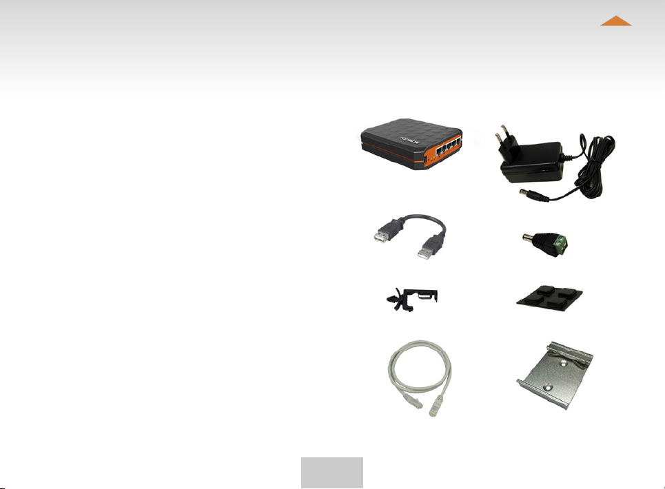
Lock 200 sales package content
TOSIBOX® Lock 200
USB Cable
Cable Saddle
Ethernet Cable
DIN Rail Bracket
Table of Contents
AC Adapter
DC Feed Plug
Rubber Feet
5

Table of Contents
3. TosIboX® Key, loCK, User InTerfaCes, mobIle ClIenTs overvIew
3.1 TOSIBOX® KEY
An intelligent USB-connected device that contains a secure
cryptoprocessor. The Key is used to establish a connection
with the Lock.
Key user interface*
*Key user interface (installed from the Key device). In the image on the
right you’ll notice TOSIBOX
TOSIBOX® Key and the network devices connected to them.
®
Lock devices that are serialized for the
6

3.2 TOSIBOX® LOCK
TOSIBOX® Lock is a device that accepts remote
connections from serialized Keys and provides access to
connected network devices. For more information, please
see glossary (page 5).
*Web user interface of the Lock. The Lock settings can be
changed via:
Service port•
Encrypted TOSIBOX•
•
Local network
Web user interface for the Lock*
®
VPN connection
Table of Contents
7

3.3 USER INTERFACE – LOCK
Table of Contents
Locks and Keys
Green: Connected
Red: Disconnected
Remotely controlled
devices
Green: Connected
Red: Disconnected
Details of the
remotely controlled
devices
8
Status bar shows
general information.
Login using
“admin” user.
Passwords can
be found on the
bottom of the Lock

4. TosIboX® Key and loCK serIalIzaTIon
The instructions below can be further claried
by seeing the accompanying diagram on the
following page.
1. Connect the TOSIBOX
Lock and wait for 2 minutes. Serialize the
Key to the Lock by inserting the Key into
the USB port of the Lock. When the LED
on the Key stops blinking, the serialization
is complete (approximately 10 seconds).
Remove the Key from the Lock. You can
also serialize additional Locks to the same
Key. After the rst Key is serialized to the
Lock, the subsequent Keys (Sub Keys) are
serialized with a computer. See section
”Multiple Keys, p.20”. Please see the
accompanying image on the next page.
2 - 3. Connect the Lock to your network
according to your use case. See section
Deploying the Lock (p.11.). Remember
to make sure that the Lock has a working
internet connection.
4. Connect the Key to your computer and
install the Key software. Follow the section
”Deploying the Key”.
5. The TOSIBOX
®
to be used to control and monitor remote
devices.
®
AC adapter to the
connection is now ready
Table of Contents
9

5. TosIboX® loCK
5.1 DEPLOYING THE LOCK
Table of Contents
With its factory default settings, the Lock is connected to
the Internet via its WAN port or a USB modem that can
be connected to the USB port of the Lock. In this mode,
the Lock creates its own protected local network for the
connected devices. Only devices that are connected to the
Lock by cable are accessible with the Key.
Notes:
See “USB modem for the Lock” (p.35) to connect a USB
modem to the Lock’s USB port.
If the Lock is connected to a DHCP enabled network via any of its •
LAN ports (LAN1, LAN2 or LAN3), the Lock’s own LAN functionality
will be lost and an error will result. LAN functionality can be restored
by resolving any DHCP conicts by removing improper LAN
connections to the Lock.
CONNECTING NETWORK DEVICES TO THE LOCK
A) Connecting network devices that use dynamic IP
addresses (DHCP)
Network devices with a DHCP client enabled will
automatically connect to the Lock. Simply plug them in and
go.
B) Connecting network devices with static IP addresses:
Assign static IP addresses to devices (from the Lock’s static IP range).1.
Go to Network > LAN and see the IP address of the Lock from 2.
”IPv4 address”. Check also that the network mask in ”IPv4
netmask” is set to 255.255.255.192.
Go to the settings of the network device. Enter an unused IP 3.
address into the device that falls within the Lock’s static IP range.
This can be found on the default (front) page of the Lock’s web user
interface.
10

Table of Contents
4. Go to the Lock’s web user interface and click “Scan for LAN
Devices”. The Lock will automatically locate all devices that match
the Lock’s IP range.
C) Conguring a Lock’s static IP address to match an
existing network
Make a note of the IP address and netmask of each controlled 1.
network device.
Select an unused address that falls within the IP address range 2.
utilized by the network devices. Go to the Lock’s settings by clicking
Network > LAN. Set the Lock’s IP address eld to “IPv4 address”
and the netmask eld to “IPv4 netmask” and leave the gateway
broadcast elds empty.
Go to Network > DHCP and set the “Start” value so that it’s higher 3.
than all used static addresses. Set the limit value to a suitable value
so that it covers the rest of the unused address in the LAN range.
For example, the range 192.168.5.50 – 192.168.5.254 contains 205
addresses so the value would be 205.
CONNECTING THE LOCK TO AN EXISTING NETWORK
IN CLIENT MODE
Client mode can be used for connecting the Lock to an
existing network (e.g. an ofce network). In this mode, the
Lock joins the network like any other device (e.g. a PC) and
provides remote users with access to other devices in the
same network. The Lock will obtain its address from the
DHCP, so the local network needs to have a working DHCP
server that allocates IP addresses.
Setting the Lock to client mode:
Log into the Lock’s web user interface as admin and open the LAN 1.
settings by clicking Network > LAN.
Change the LAN interface protocol eld to “DHCP client”. Click the 2.
“Switch protocol” button and click “Save”.
Connect a cable from the local network to one of the Lock’s LAN 3.
ports (e.g. LAN3).
Notice in client mode:
Do not connect the Internet to the Lock’s WAN Port or a USB •
modem to the USB port. Doing so will automatically deactivate
the client mode and revert the Lock’s LAN settings back to factory
defaults.
•
Do not connect any LAN port directly to the Internet.
Do not connect the controlled devices to the Lock’s LAN ports.•
The Lock will scan the entire LAN network for connected devices and •
will grant device access to any user with a serialized Key. Please keep
this in mind when considering network and information security.
•
In cases where access rights need to be restricted, switch on MAC/
IP ltering (under Advanced settings) or set up the Lock in its factory
default conguration.
•
In this mode, the Lock’s inbuilt rewall does not protect the devices
in the LAN network.
11
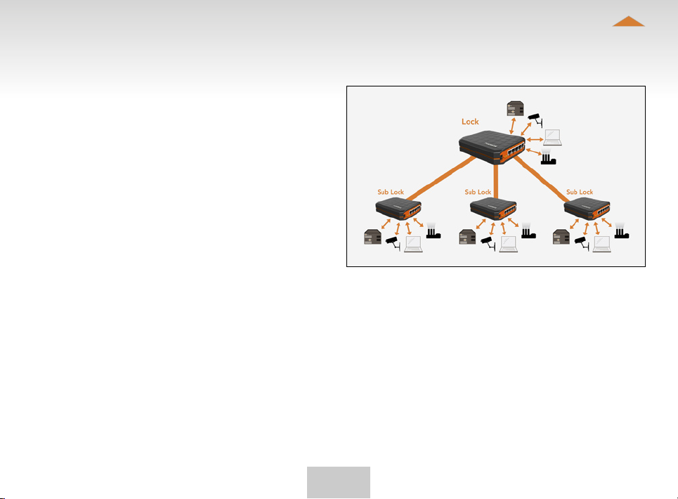
5.2 CONNECTING LOCKS
With TOSIBOX® Locks one can connect machines in
separate places so that the connection between them is
permanently and automatically on. One example is a real-
time protected connection between home and ofce. This
is made with a Lock/Sub Lock solution (see accompanying
image Connecting Locks). Up to 10 Sub Locks can be
connected to one Lock.
First serialize the Key to all the Locks to be connected
as described in section “TOSIBOX
serialization”.
Connecting Locks
Insert a serialized Key to the USB port of the computer.1.
Choose ”Devices” from the Key user menu and ”Connect Locks” 2.
from the drop down menu.
Choose the Locks that you want to connect together and choose 3.
”Next”.
Choose the Lock that you want to attach the Sub Locks. The other 4.
Locks will be changed to Sub Lock operating mode.
Conrm the selection > Save > serializing is ready. 5.
Note: The connections will come into effect when the
Locks have access to the Internet.
The Sub Lock ends of the connection in the picture do not
have their own DHCP service. If the connection between
the Lock and the Sub Lock is interrupted, the network
devices connected with the Sub Lock can no longer
connect to the Internet and each other.
®
Lock and Key
Table of Contents
12

Table of Contents
5.3 UPDATING THE LOCK SOFTWARE
Connect the computer to the service port of the Lock with 1.
an ethernet cable. First check that you have access to the
Internet via the service port. Open an internet browser and type
http://172.17.17.17 or http://service.tosibox into the address eld
to access the Lock user interface.
Do not type “www” before the “http://” in either address.
Alternatively you can also log in remotely using the ³admin² user
ID. When the connection between the Key and the Lock is active,
double click the Lock symbol in the Key user interface. Log in using
“admin” for the user ID. The admin password is visible on the
bottom of the Lock.
Choose “Settings” > “Software update”. If there is a software 2.
update available for the Lock, you can start the update by clicking
the “Start software update” button.
Wait until the update has been downloaded and installed. Do not 3.
interrupt the power of the Lock during the software update process.
The update is complete when the software gives a notice “Software
updated successfully”.
Automatic software updates are activated as a default
setting. You can select the time when the automatic update
of the released software is allowed. You can deactivate the
automatic software update from the Lock user interface.
Choose “Settings” > “Software update” > uncheck the box
“Auto-update enabled”.
5.4 USB MODEM SETTINGS FOR THE LOCK
You can connect the Lock to the Internet with a USB
Modem. For information on supported modems go to:
http://help.tosibox.com
Log in as admin user, select “Network” > “USB Modem”.4.
Fill in the APN and if necessary the PIN eld according to the SIM 5.
card settings. For APN settings information, please contact your
mobile operator.
Conrm the selection > Save.6.
Connect a Tosibox supported USB Modem to the USB port of the 7.
Lock.
5.5 KEY CONNECTION SETTINGS FOR THE LOCK
You can allow connections from Lock to Key. Log into the
Lock as admin,
select “Settings” > “Keys and Locks” > remove selection
“Deny access towards client” You can change the Key
connection type from Layer 3 -routed to
Layer 2 -bridged (“Connection type” > “Layer 2 -bridged”).
13

Table of Contents
5.6 ADVANCED SETTINGS FOR THE LOCK
On the Advanced settings page you can congure LAN
and Internet access restrictions and security related
settings.
Log in as admin8.
Choose “Settings” > “Advanced settings”9.
Conrm changes > Save 10.
5.7 INTERNET CONNECTION PRIORITIES
Several alternative internet connections can be used by the
Lock. One of the available connections can be selected as
a main connection and the other connections can be set as
backup connections. In the event that the main connection
is interrupted, the connection is automatically shifted to
preselected backup connections according to the priority
setting (eg. WAN port --> USB Modem).
5.8 PoE
The “PoE out” port supports PoE output, with auto
detection feature. This means you can connect laptops
and other non-PoE devices without damaging them. The
PoE on “PoE out” outputs approximately 2V below input
voltage and supports up to 0.58A (So e.g. 24V PSU will
provide 22V/0.58A output to the “PoE out” port).
The device accepts powering from the power jack or from
the “PoE in” port (passive PoE)
DC power jack (5.5mm outside and 2mm inside diameter, female •
center pin positive) accepts 8-27V DC +/-10%
•
The “PoE in” port accepts passive Power over Ethernet 8-27V DC
+/-10%
Under maximum load, the power consumption of this
device is 7W.
14

5.9 MOUNTING INSTRUCTIONS
Installation to DIN rail
The Lock can be installed to DIN rail with the clip and
screws included in the sales package. There are M3
grooved mounting holes on three sides of the equipment.
For attachment on either of the narrow sides, the screws
with length of 10 mm shall be used. For attachment on the
bottom of the Lock, the screws with length of 6mm shall
be used. The screws shall be placed through the bottom
sticker which has the hole locations indicated.
Please see pictures 1 - 4 for the mounting options.
Table of Contents
Picture 1.
Picture 2. Picture 3.
15

Picture 4.
Table of Contents
Using the rubber feet
Rubber feet included in the sales package can be installed
in the bottom of the Lock for more convenient installation
horizontally e.g. on a table.
Please see picture 5 and 6 for the mounting.
Picture 5.
Picture 6.
16

5.10 INPUT POWERING OPTIONS
Using the DC input plug
In case the operating voltage of 8-27V DC +/-10% is
available from an external power source with only stripped
wires, a DC input plug included in the sales package can
be used. The polarity marking in the plug shall be observed
and use of the cable saddle is recommended.
Please see picture 7 for the mounting.
Using the cable saddle
To secure the input power cable from being accidentally
pulled away from the power input jack, a cable saddle is
included in the sales package. The cable saddle is locked
in place by inserting it into the 4mm diameter hole in the
front panel.
Please see picture 8 for the mounting.
Table of Contents
17

Picture 7.
Picture 8.
Table of Contents
18

6. TosIboX® Key
Table of Contents
6.1 TAKING THE MASTER KEY INTO USE
Insert the serialized Key into the USB port of your computer. You 1.
should notice an auto play window open up on your desktop. If
not, double click the executable le located in the Key’s folder
(Setup_Tosibox.exe). If your computer asks whether you want to
allow Tosibox to make changes to your computer click yes.
The Key software will ask for a password that you can enter if you 2.
wish (recommended). By entering a password, you can prevent the
unauthorized use of the Key. Store the password safely.
The Key software opens up a window that shows the Locks that 3.
have been serialized to the Key. Connect the Key with the wanted
Lock by clicking the Lock’s “Connect” icon.
The Key info dialogue shows the status of the connection between 4.
the Key and Lock.
The Key is now ready to be used
The Lock symbol displays a different colour according to
the operating status of the Lock:
Red = The Lock is connected to the Internet and the Key has a •
remote connection to the Lock.
•
Yellow = The Lock is connected to the Internet, but the Key doesn’t
have a remote connection to the Lock.
•
Green = The Lock is not connected to the Internet.
The Key symbol located in the computer’s task bar
displays different colours according to the operating
status of the Key:
Red = The Key is not connected to the Internet.•
Yellow = The Key is connected to the Internet, but not to any found •
Locks.
•
Green = The Key is connected to at least one Lock.
19

1. DEPLOYING THE KEY
2. SETTING THE PASSWORD
Table of Contents
3. KEY USER INTERFACE
20

KEY USER INTERFACE
Picture 1.
Picture 3.
Double click to open
Lock user interface
Table of Contents
Picture 2.
21

Table of Contents
6.2 RENAMING AND USING DEVICES
Picture 1.
This is the start window for the Key user interface. You can
open the Lock user interface by double clicking the Lock
icon on the left side of the window.
Picture 2.
By clicking an extra menu opens.
Click “Open browser automatically when connected” to have the 1.
Lock user interface launch automatically when the Key connects
to the Lock.
Selecting “Show all details” allows you to view all the details of 2.
the connected device.
Click “Rename device” to rename the selected device. Lock 3.
names are Key specic, so a Lock’s name change will be reected
only with the Key that was used to change it.
Picture 3.
You can open the browser user interface of the controlled device 1.
in “Open with browser (http)”.
You can connect to network sharing in “Open windows network 2.
share”.
You can open the remote desktop connection in “Open Remote 3.
Desktop Connection (RDP), if available”.
You can check the functionality of the controlled device with PING 4.
command in “Check if host available (PING)”.
6.3 ADDING EXTRA KEYS
Additional Keys can be serialized to a Lock.
Insert a previously serialized Key into the USB of your computer.1.
Insert a new Key to another USB port of the computer. 2.
Picture 1.
Wait until ”New Key” window opens.3.
If you are adding a sub key, do next the steps 1-4 ADDING SUB 4.
KEY.
If you are adding a backup key, do the steps 1-4 ADDING BACKUP
KEY.
22

ADDING SUB KEY
Table of Contents
When a new Key is 1.
turned into a Sub Key,
choose ”Sub Key”,
provide a descriptive
name for it, and click
”Next”. A Sub Key
is able to connect to
chosen Locks but it has
no rights to serialize new
Keys.
Conrm the selection 3.
by pressing ”Save”.
Serialization for the extra
Key is now complete.
Select the Lock(s)/Sub 2.
Lock(s) to which you
want to serialize the
extra Key and choose
”Next”.
Serializations of additional keys can be removed 4.
in the Lock user interface by clicking “Edit Tosibox
devices” (admin only).
23

ADDING BACKUP KEY
Table of Contents
Choose ”Backup Key” 1.
and press ”Next”. All
serializations and user
rights are automatically
synchronized between
the Backup Keys.
The Backup Key is now 3.
created. Press ”Close”
button to exit the
feature.
Conrm by pressing 2.
”Save”.
The Backup Keys can be managed later in the Key user interface 4.
under ”Manage Keys”. Important: This feature creates a Backup
Key with equal user rights. Later, when the new locations are
deployed by the other Key, the access rights are automatically
copied to both Keys.
24

EXTRA KEY USE CASE
Table of Contents
25

Table of Contents
6.4 REMOTE SERIALIZATION OF EXTRA KEYS
This feature is only available for Keys that have already
been serialized locally.
Insert the Key into the USB port of the computer and wait for the 1.
TOSIBOX® Key application to start.
Choose ”Manage Keys” from the “Devices” menu in the user 2.
interface and open the “Sub Keys” tab.
Choose the extra Keys to which you want to serialize new Locks and 3.
press the ”Serialize...” button.
Choose the Locks to which you want to serialize the extra Keys and 4.
press the ”Next” button.
A list of targeted Locks is displayed. Conrm serialization and click 5.
“Save”.
Serialization of the extra Keys is now complete. Press “Finish” 6.
button to exit the wizard.
6.5 PUK CODE FOR THE KEY
In the event that a wrong Key password has been entered six 1.
consecutive times, the Key will be locked. To unlock the Key a
personal unlocking code, PUK is needed. The PUK code is delivered
with the Key. Store it safely.
Go to the ”Password” menu in the Key software and choose 2.
”Change password using PUK code...”.
Enter the PUK code into the ”PUK-code” eld.3.
Enter a new password into the ”New password” eld.4.
Conrm your password by typing it once more into the “New 5.
password (again)” eld.
Choose ”OK”.6.
26

7. mobIle ClIenT
7.1 MOBILE CLIENT FOR ANDROID DEVICES
Table of Contents
1. Download and install
the TOSIBOX® Mobile
Client from the Google
Play store.
2. Open the TOSIBOX® Key
software by plugging a
serialized Key into the USB
port of your computer.
27
3. Go the software menu and select
Devices > Manage Keys.

Table of Contents
4. Select the mobile clients tab and click
Add new...
5. Enter the name of your mobile
device and click Next.
28
6. Select the Locks that you would
like to access through your mobile
device and click Next.

Table of Contents
7. Open the TOSIBOX®
Mobile Client on your
device.
8. Tap the screen to start
serialization.
29
9. Scan the QR code displayed on your
computer or enter the serialization
code where prompted on your
device.

Table of Contents
10. Click Finish once the the serialization
is complete.
11. Create a password for
the mobile client.
30
12. Connect to a Lock by
selecting its on/off
icon.

Table of Contents
Table of Contents
13. Check the I trust this
application dialogue
box and click OK.
Congratulations! You’re done! Now your mobile client is serialized and can
connect to the selected Locks and devices connected to them.
You can open network devices through your web browser (if available)
by clicking the the appropriate globe icon. Note: If your network device
does not have a web interface (HTTP / HTTPS), you can use a third party
application to make the connection. You can nd third party applications
from the Google Play store or App Store. You can copy the network device
IP address to the device’s clipboard by clicking the IP button. Doing so will
allow you to paste the IP address to a third party application.
31
31

7.2 MOBILE CLIENT FOR IPHONES AND IPADS
Table of Contents
1. Download and
install the TOSIBOX®
Mobile Client from
the App Store.
2. Open the TOSIBOX® Key
software by plugging a
serialized Key into the USB
port of your computer.
32
3. Go the software menu and select
Devices > Manage Keys.

Table of Contents
4. Select the Mobile Clients tab and click
Add new...
5. Enter the name of your mobile
device and click Next.
33
6. Select the Locks that you would
like to access through your mobile
device and click Next.

Table of Contents
iOS
7. Open the TOSIBOX®
Mobile Client on
your device.
iOS
8. Tap the screen to
start serialization.
34
9. Scan the QR code displayed on your
computer or enter the serialization
code where prompted on your
device.

Table of Contents
10. Click Finish once the the serialization
is complete.
11. Create a password
for the mobile client.
35
12. Connect to a Lock by
selecting its on/off
icon.

Table of Contents
Table of Contents
13. On the rst time
when connecting
to a Lock, the user
needs to authorize
the installation of
the VPN prole by
entering the device
passcode.
Congratulations! You’re done! Now your mobile client is serialized and can
connect to the selected Locks and devices connected to them.
You can open network devices through your web browser (if available)
by clicking the the appropriate globe icon. Note: If your network device
does not have a web interface (HTTP / HTTPS), you can use a third party
application to make the connection. You can nd third party applications
from the Google Play store or App Store. You can copy the network device
IP address to the device’s clipboard by clicking the IP button. Doing so will
allow you to paste the IP address to a third party application.
36
36

9. TroUbleshooTIng
Table of Contents
10. maInTenanCe InsTrUCTIons
The Key software cannot be installed:
Check whether your computer has an operating system supported •
by TOSIBOX®: Windows XP/SP3, Windows Vista, Windows 7,
Windows 8, Windows 10, Windows 8.1 and Mac Leopard 10.5 or
more recent version.
•
Restart the computer and reattach the Key.
The Key’s connection window does not show the
connections:
The computer is not connected to the Internet.•
The Key is not serialized to the Lock.•
The Lock does not have an internet connection or is not connected •
to the AC adapter.
The Lock connection in the window remains yellow:
The Key has found a Lock, but VPN has not yet been established.•
Device connections or the Lock connection in the window
remains red:
Make sure the controlled devices are connected to the Lock.•
If connected wirelessly, use the ethernet service port to log in to •
the Lock. Check that the wireless connection is enabled and that
the Lock and the controlled device have the same password and
encryption settings.
•
Make sure the controlled device has a DHCP-service. If not, add the
device in the device list of the Lock and specify the IP address of the
device .
Go to http://help.tosibox.com for more instructions.
TOSIBOX® devices should be treated with care. By
observing the following instructions you can enjoy the
maximum performance of the devices and ensure full
warranty coverage.
Keep the devices dry. Protect the devices from precipitation, •
moisture and liquids. They can cause corrosion to electronic circuits.
The devices are intended for indoor use only. Do not use them in
wet locations or outdoors.
•
Protect the devices from dirt and dust. When necessary, clean
the devices with a soft, dry cloth. Do not use chemicals, solvents,
detergents or pressurized air.
•
Protect the devices from heat. High temperatures can damage
plastic parts and shorten the life of the electronics.
•
Protect the devices from cold. Low temperatures can make them
more susceptible to breakage. Let the device’s temperature stabilize
long enough before deploying them into the network..
•
Protect the devices from mechanical shocks. Do not shake, knock or
drop the devices.
•
Do not paint the devices.
Do not cover the devices or install them on top of each other. This •
can cause overheating. Allow enough free space around the devices
to ensure the free ow of cooling air.
•
Do not open the devices. There are no serviceable parts inside the
devices. If the devices malfunction or need servicing, contact an
authorized service facility.
•
After the service life of the devices is over, do not throw them
into domestic waste. Instead, take them to an authorized waste
electronics collection facility.
37

11. TeChnICal daTa
Table of Contents
11.1 TOSIBOX® LOCK 200
Ports:
1 x USB 2.0, type A•
1 x RJ-45 WAN connection, 10/100 Mb/s, auto-negotiation (MDI / •
MDI-X)
•
3 x RJ-45 LAN connection, 10/100 Mb/s, auto-negotiation (MDI /
MDI-X)
•
1 x RJ-45 Service connection, 10/100 Mb/s, auto-negotiation (MDI
/ MDI-X)
Connections:
DC input power jack 5.5/2.1mm, 8-27V DC +/-10%, reverse polarity •
protected
•
PoE input 8-27V DC +/-10% (WAN port), PoE output (LAN3 port,
580 mA max)
•
The product must be powered by limited energy according to
chapter 9.4 of IEC / UL 61010-1 3rd edition
•
DIN rail mounting bracket M3 threads on three sides
Maximum power consumption is 7 W•
WAN connection features:
Independent of operating systems•
Works in all Internet connections (operator independent)•
Firewall friendly•
Works with dynamic, static and private IP addresses•
Built-in rewall, NAT•
Up to 50 concurrent VPN connections•
VPN throughput up to 15 Mb/s•
Mobile connection features:
Supported 3G/4G USB modems: Huawei E3372, E3276, E392, E372, •
E3531, E3131, E353, E367, E160, E169, E173, E176, E180, E1552,
Tosibox 3G modem
•
Automatic network recovery that recovers from most mobile
operator and modem problems
Included accessories
USB extension cable•
Ethernet cable•
AC adapter: Input 100 – 240V AC, 50/60Hz, Output 24.0V DC, 0.8A•
DIN rail mounting bracket•
Cable saddle•
DC input plug•
Physical properties
140 mm (L) x 36 mm (W) x 125 mm (H)•
Weight 0.53 kg•
Operating temperature -20 °C … +50 °C•
Operating humidity 20 – 80% RH, non condensing•
Maximum operating altitude 10000 ft. / 3000 m•
Storage temperature -40 °C … +70 °C•
Overvoltage category I•
Cast aluminium casing•
IP protection class: IP20•
38

11.2 TOSIBOX® KEY 200
1024 bit RSA key in the cryptographic module•
4 GB or larger ash memory storage for Tosibox Key software and •
settings
•
USB 2.0 interface, type A
Standard CSP/PKCS#11•
Supported operating systems:
Windows 10, Windows 8/8.1 (32/64 bit), Windows 7 (32/64 bit), •
Windows Vista (32/64 bit)
•
Windows XP (SP3), Windows Server 2003
Mac OS X Leopard 10.5 or more recent (Intel)•
Physical properties
83 mm (L) x 22 mm (W) x 10 mm (H)•
Weight 29 g•
Casing aluminium + plastic•
Operating temperature 0 °C … +70 °C•
Storage temperature -20 °C … +85 °C•
Table of Contents
39

12. lImITed warranTy
(United States and Canada)
Subject to the exclusions set forth below, Tosibox Oy
will repair or replace, at its option without charge, any
TOSIBOX product which fails due to a defect in material
or workmanship within Two Years following the initial
consumer purchase.
This warranty does not apply to water damage, abuse or
misuse of unauthorized accessories, unauthorized service
or modication or altered products.
This warranty does not include the cost of labor for removal
or re-installation of the product.
Table of Contents
ANY IMPLIED WARRANTIES, INCLUDING, WITHOUT
LIMITATION THE IMPLIED WARRANTIES OF
MERCHANTABILITY AND FITNESS FOR A PARTICULAR
PURPOSE, SHALL BE LIMITED AS SET FORTH HEREIN
AND TO THE DURATION OF THE LIMITED WARRANTY,
OTHERWISE THE REPAIR OR REPLACEMENT AS
PROVIDED UNDER THIS EXPRESS LIMITED WARRANTY IS
THE EXCLUSIVE REMEDY OF THE CONSUMER AND IS
PROVIDED IN LIEU OF ALL OTHER WARRANTIES,
EXPRESS OR IMPLIED. IN NO EVENT SHALL TOSIBOX
OY BE LIABLE, WHETHER IN CONTRACT OR TORT
(INCLUDING BUT NOT LIMITED TO NEGLIGENCE,
GROSS NEGLIGENCE, BODILY INJURY, PROPERTY
DAMAGE AND DEATH) FOR DAMAGES IN EXCESS OF
THE PURCHASE PRICE OF THE PRODUCT
OR ACCESSORY, OR FOR ANY INDIRECT, INCIDENTAL,
SPECIAL OR CONSEQUENTIAL DAMAGES OF ANY KIND,
OR LOSS OF REVENUE OR PROFITS, LOSS OF BUSINESS,
LOSS OF INFORMATION OR DATA OR OTHER
FINANCIAL LOSS ARISING OUT OF OR IN CONNECTION
WITH THE ABILITY OR INABILITY TO USE THE PRODUCTS
OR ACCESSORIES TO THE FULL EXTENT THESE
DAMAGES MAY BE DISCLAIMED BY LAW.
40

13. PaTenTs
Table of Contents
14. legal noTICes
TOSIBOX® technology is internationally patented.
Patents AU2012260775, AU2013208840, JP5687388,
JP5657146, KR10-1392356, FI124237, FI123551,
FI124341, US8831020. Patents pending AU2013244872,
AU2012220456, BR1120130214430, BR1120130301406,
BR1120140249342, BR 11 2014 016909 8, EP13735938.6,
EP12788813.9, EP12748933.4, EP13772027.2, IN9022/
DELNP/2014, IN7185/CHENP/2013, 10104/CHENP/2013,
IN5910/CHENP/2014, JP2014-202978, JP2014-550741,
JP2015-503907, CA2869110, CA2860680, CA2826636,
CA2834147, CN201280025225.1, CN201280009926.6,
CN201380012759.5, CN201380018278.5, KR(PCT)102013-7034348, KR10-2014-7022279, KR10-20147031032, MX/A/2014/012002, MX/A/2014/008449,
MX/A/2013/013745, MX/A/2013/009651, FI20125022,
US14/119753, US14/370872, US14/390153,
RU2014141363, RU2014131719, RU2013141073,
RU2013156005.
© 2015 Tosibox Oy. All rights reserved.
Reproduction, distribution or storage of part or all of
the content of this document without the prior written
permission of Tosibox is prohibited.
Because of continuous product development, Tosibox
reserves the right to change and improve any product
mentioned herein without prior notice.
Tosibox shall not take responsibility of any loss of
information or income or any special, incidential,
consequential or indirect damages.
The contents of this document are provided ”as is”. No
warranties of any kind, either express or implied, including,
but not limited to, the implied warranties of merchantability
and tness for a particular purpose, are made in relation
to the accuracy, reliability or contents of this document.
Tosibox reserves the right to revise this document or
withdraw it at any time wihout prior notice.
Tosibox products contain technology that is based on
open source software. When requested by the customer,
Tosibox will deliver more detailed information from the
parts that the licenses require.Source code requests can be
submitted to:
sourcecode.request@tosibox.com or by mail:
Tosibox Oy
Elektroniikkatie 10
90590 OULU, FINLAND
42

15. deClaraTIons
Table of Contents
15.1 DECLARATION OF CONFORMITY
Hereby, Tosibox Oy declares that TOSIBOX® Lock is
in compliance with the essential requirements of the
European directives:
1999/5/EC, article 3.1 a) 3.1 b) and 3.2; R&TTE / EMC •
2011/65/EC; RoHS •
2006/95/EC; Low Voltage •
2009/125/EC; ErP (Regulation 287/2009/EC)•
In Oulu, Finland, 1.5.2015
Tosibox Oy
Tero Lepistö, CEO
15.2 FEDERAL COMMUNICATION COMMISSION INTERFERENCE STATEMENT
This device complies with FCC part 15 of the FCC rules.
Operation is subject to the following two conditions: (1)
This device may not cause harmful interference, and (2) this
device must accept any interference received, including
interference that may cause undesired operation.
FCC Caution: Any changes or modications not expressly
approved by the party responsible for compliance could
void the user´s authority to operate this equipment.
43
 Loading...