

Toshko SRX M5000, M5000 User Manual

DIGITAL VIDEO RECORDER
USER GUIDE
8/16 CHANNELS
VER M5-3.01
• Thank you for purchasing this Digital Video Recorder.
• Before using the Digital Video Recorder, please ensure that you read and
understand the User Guide.
• Please store the User Guide at an easily accessible location.
• Before connecting and installing any third party cameras, monitors, alarms and
computers, please refer to the appropriate instruction manual for proper operation.
1 DIGITAL VIDEO RECORDER
SAFETY PRECAUTIONS
CAUTION:
TO REDUCE THE RISK OF ELECTRIC SHOCK, DO NOT REMOVE COVER (OR BACK).
NO USER SERVICEABLE PARTS INSIDE. REFER SERVICING TO QUALIFIED
SERVICE PERSONNEL.
The lightning flash with arrowhead symbol, within an equilateral
triangle, is intended to alert the user to the presence of un insulated
“dangerous voltage” within the product’s enclosure that may be of
sufficient magnitude to constitute a risk of electric shock to persons.
The exclamation point within an equilateral triangle is intended to alert
the user to the presence of important operating and maintenance
(servicing) instructions in the literature accompanying the appliance.
WARNING:
TO PREVENT FIRE OR ELECTRIC SHOCK HAZARD,
DO NOT EXPOSE THIS APPLIANCE TO RAIN OR MOISTURE.

2 DIGITAL VIDEO RECORDER
Contents
■ Safety Precautions ……………………………………………………………………………………… 1
■ Contents ………………………………………………………………………………………………… 2
■ Disclaimer ……………………………………………………………………………………………… 4
■ Warning ………………………………………………………………………………………………… 4
■ Caution ………………………………………………………………………………………………… 6
■ Preventing Malfunction………………………………………………………………………………… 6
■ Package Contents……………………………………………………………………………………… 7
■ Controls
Front Panel ……………………………………………………………………………………… 8
Buttons …………………………………………………………………………………………… 8
Rear Panel Connectors ………………………………………………………………………… 10
Remote Controller ……………………………………………………………………………… 11
■ Installation & Connections …………………………………………………………………………… 12
Camera, Monitor, Microphone, Alarm sensor and Power cord
Alarm inputs and Alarm outs
Pan/Tilt/Zoom Connections
PC system requirement for NETWORK Connection
■ Quick Start ………………………………………………………………………………………………… 17
■ Live Viewing
Display Overview ………………………………………………………………………………… 19
Multiscreen Display and Sequencing…………………………………………………………… 20
Zooming ……………………………………………………………………………… 22
■ Operation
Main Menu Overview ……………………………………………………………………………… 23
Display Option ………………………………………………………………………………… 24
Camera Setup …………………………………………………………………………………… 26
Motion Recording ………………………………………………………………………………… 28
Normal Recording ………………………………………………………………………………… 30
Alarm Recording ………………………………………………………………………………… 32
Schedule Recording ……………………………………………………………………………… 36
Network Setup ……………………………………………………………………………… 39
System Setup ……………………………………………………………………………… 42
■ Pan/Tilt Zoom Control …………………………………………………………………………… 47

3 DIGITAL VIDEO RECORDER
■ Search/Playback …………………………………………………………………………… 50
Time Search ………………………………………………………………………………… 51
Log List Search ……………………………………………………………………………… 48
■ External Search …………………………………………………………………………… 52
■ Back up …………………………………………………………………………… 53
Built-in CD RW ……………………………………………………………………………… 53
External USB HDD …………………………………………………………………………… 56
FTP Server ……… ………………………………………………………………………… 58
USB Flash Memory(Snap shot) ………………………………………………………………… 59
Backup Range Setup … ………………………………………………………………… 60
■ Client Program …………………………………………………………………………… 61
Install ………………………………………………………………………………… 62
Features ……………………………………………………………………………… 65
DVR Control ……………………………………………………………………………… 76
Virtual DVR ……………………………………………………………………………… 100
■ Appendix
PSTN Modem ……………………………………………………………………………… 104
Web CMS … … … ……………………………………………………………………………… 111
View Only …… ……………………………………………………………………………… 114
AVI Converting …… ……………………………………………………………………………… 115
■ Specification ……………………………………………………………………………………… 117

4 DIGITAL VIDEO RECORDER
Disclaimer
z The information in this manual is believed to be accurate and reliable as of the date of
publication. The information contained herein is subject to change without notice. Revisions
or New editions to this publication may be issued to incorporate such change
z We makes no warranties for damages resulting from corrupted or lost data due to a mistaken
operation or malfunction of the Digital Video Recorder, the software, the hard drives, personal
computers, peripheral devices, or unapproved/unsupported devices.
Warning
z Do not cover the ventilation opening or slots on the outer casing. To prevent the appliance
from overheating, provide at least two inches of air space around the vent and the slots.
z Do not drop metallic parts through slots. This could permanently damage the Digital Video
Recorder. Immediately turn the DVR’s power off or unplug the power cord from the power
outlet. Contact a qualified service personnel authorized by your equipment distributor
z Do not attempt to disassemble or alter any part of the equipment that is not expressly
described in this guide. Disassembly or alteration may result in high voltage electrical shock.
Qualified service personnel authorized by your equipment distributor should conduct internal
inspections, alterations and repairs.
z Stop operating the equipment immediately if it emits smoke or noxious fumes. Failure to do
so may result in fire or electrical shock. Immediately turn the DVR’s power off, remove the
power cable from the power outlet. Confirm that smoke and fume emissions have ceased.
Please consult your DVR distributor.
z Stop operating the equipment if a heavy object is dropped or the casing is damaged. Do not
strike or shake. Failure to do so may result in fire or electrical shock. Immediately turn the
DVR’s power off or unplug the power cord from the power outlet. Please consult your DVR
distributor.
z Do not allow the equipment come into contact with, or become immersed in, water or other
liquids. Do not allow liquids to enter the interior. The DVR has not been waterproofed. If
the exterior comes into contact with liquids or salt air, wipe it dry with a soft, absorbent cloth.
In the event that the water or other foreign substances enter the interior, immediately turn the
DVR’s Power off or unplug the power cord from the power outlet. Continued use of the
equipment may result in fire or electrical shock. Please consult your DVR distributor.

5 DIGITAL VIDEO RECORDER
z Do not use substances containing alcohol, benzene, thinners or other flammable substances
to clean or maintain the equipment. The use of these substances may lead to fire. Use a
dry cloth on a regular periodic basis and wipe away the dust and dirt that collects on the
device. In dusty, humid or greasy environments, the dust that collects around the ventilation
or the slots on the outer casing over long periods of time may become saturated with
humidity and short-circuit, leading to fire.
z Do not cut, damage, alter or place heavy items on the power cord. Any of these actions
may cause an electrical short circuit, which may lead to fire or electrical shock.
z Do not handle the device or power cord if your hands are wet. Handling it with wet hands
may lead to electrical shock. When unplugging the cord, ensure that you hold the solid
portion of the plug. Pulling on the flexible portion of the cord may damage or expose the
wire and insulation, creating the potential for fires or electrical shocks.
z Use only the recommended power accessories. Use of power sources not expressly
recommended for this equipment may lead to overheating, distortion of the equipment, fire,
electrical shock or other hazards.
z Do not place the batteries near a heat source or expose them to direct flame or heat.
Neither should you immerse them in water. Such exposure may damage the batteries and
lead to the leakage of corrosive liquids, fire, electrical shock, explosion or serious injury.
z Do not attempt to disassemble, alter or apply heat to the batteries. There is serious risk of
injury due to an explosion. Immediately flush with water any area of the body, including the
eyes and mouth, or clothing that comes into contact with the inner contents of the battery. If
the eyes or mouth contact these substances, immediately flush with water and seek medical
assistance from a medical professional.
z Avoid dropping or subjecting the batteries to severe impacts that could damage the casings.
It could lead to leakage and injury.
z Do not short-circuit the battery terminals with metallic objects, such as key holders. It could
lead to overheating, burns and other injuries.
z The supplied power supply and power cord are designed for exclusive use with the Digital
Video Recorder. Do not use it with other products or batteries. There is a risk of fire and
other hazards.

6 DIGITAL VIDEO RECORDER
Caution
z Do not operate the appliance beyond its specified temperature, humidity or power source
ratings. Do not use the appliance in an extreme environment where there is high
temperature or high humidity. Use the device at temperatures within +0°C - +40°C (32°F -
104°F) and humidity below 90 %. The normal operating power source for this device is
100V-240V AC 50/60Hz.
Preventing Malfunction
z Avoid Strong Magnetic Fields. Never place the DVR in close Proximity to electric motors or
other equipment generating strong electromagnetic fields. Exposures to strong magnetic
fields may cause malfunctions or corrupt image data.
z Avoid Condensation Related Problems. Moving the equipment rapidly between hot and cold
temperatures may cause condensation (water droplets) to form on its external and internal
surfaces. You can avoid this by placing the equipment in an airtight, resalable plastic bag and
letting it adjust to temperature changes slowly before removing it from the bag.
z If Condensation forms inside the Digital Video Recorder. Stop using the equipment
immediately if you detect condensation. Continued use may damage the equipment. Remove
the power cord from the power outlet and wait until the moisture evaporates completely
before resuming use.
CAUTION “Risk of Explosion if Battery is replaced by an Incorrect Type. Dispose of Used
Batteries According to the Instructions.

7 DIGITAL VIDEO RECORDER
PACKAGE CONTENTS
Please check the package and contents for visible damage. If any components are damaged or
missing, do not attempt to use the unit, contact the supplier immediately. If the unit must be
returned, it must be shipped in the original packing box.
CONTENTS QUANTITY REMARK
DIGITAL VIDEO RECORDER 1 UNIT
CLIENT SOFTWARE CD 1
REMOTE CONTROLLER 1
Audio In Cable Connector 1 (8ch) or 2(16ch)
RS-422 Connector * 1
BATTERY (AAAsize) 2
POWER CORD 1
USER GUIDE 1
* This RS-422 is not a converter and it can be only used in this DVR.

8 DIGITAL VIDEO RECORDER
CONTROLS
Front Panel
Buttons
POWER button
y Press this button to turn the power on; press again to turn the power off.
The POWER LED (red) lights/goes off when the power is on/off.
Numeric Buttons
(1~16)
y These buttons have a number of functions to enter data and to make
selections. They are used to enter numerical data when prompted for the
password, to make channel/camera selection, to choose the day in
schedule option, and to enter alphabets to label each channel.
Mode Indicator
y Five LEDs display the status of the Digital Video Recorder. From the left,
Power (red), Recording (red), Scheduled Recording (green), Lock (green)
and Network (green).
Playback / Record
Control
y Used to Start and Stop Recording or Playback.
Shuttle Ring
y Used to control the playback speed, and to rewind or forward the image.
JOG Dial
y Used to forward or reverse the image during playback (field-by-field).

9 DIGITAL VIDEO RECORDER
Remote control
signal receiver.
y Do not block the receiver as the remote controller needs the line of sight to
the receiver.
y [DISPLAY] : Press this button to display the cameras in multi-screen mode
or to switch sequence function.
y [ZOOM]: Press this button to display zoom area box; press [ENTER]
to enlarge the image. Pressing cursors can move this zoom area.
Screen Control
Buttons
y [P/T/Z/FOCUS]: Press this button to control a PAN/TILT/ZOOM camera
via RS-485 connection.
y [SCHEDULE]: Press this button to make scheduled recording standby.
The SCHEDULE LED (green) lights/goes off when the schedule is on/off.
y [TIME SEARCH]: Press this button to display the Time Search menu.
y [LOG] : Press this button to display log list.
Press this button to display the Alarm Search menu.
y [REC] : Press this button to start recording.
Function Buttons
y [SHUTTLE HOLD]: This button retains the selected playback or reverse
playback speed.
It is also used for controlling Spot out while it’s Live viewing.
y [ENTER]: Press this button to save menu settings
y [CANCEL]: Press this button to exit menu without saving.
y [-, +] : To Decrease settings , To Increase settings
y [Direction STWX]: In Menu setup mode, used to move the cursor.
In Zoom mode, used to move the zoom area.
MENU Button
y [MENU]: Press this button to display the MAIN MENU screen.
y [BACKUP]: Press this button to begin making a backup copy of the hard
drive. If there is no peripheral recording device connected, this button cannot
be used.
Backup Button
y [EXT. SEARCH]: Press this button to start external HDD search.
LOCK Button
y Press this button to lock all units’ key buttons including the remote
controller. The LOCK LED (green) lights/goes off when the lock is on/off. To
release press it again and enter the administer password.
10 DIGITAL VIDEO RECORDER
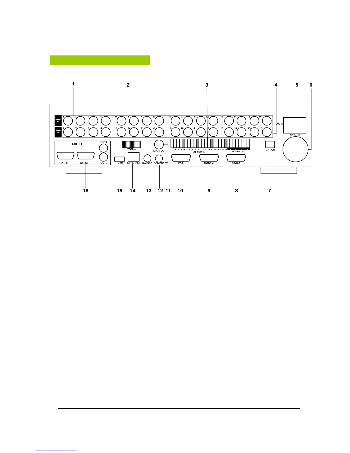
Rear Panel Connectors
1) Camera Inputs: BNC input connectors,
2) 75 Ohm Termination
3) ALARM IN/OUT: For connecting alarm inputs (1~16) and alarm out relays (1~4).
4) Camera Outputs: BNC output (looping) connectors.
5) AC power socket
6) Power Fan
7) Option: Not supported
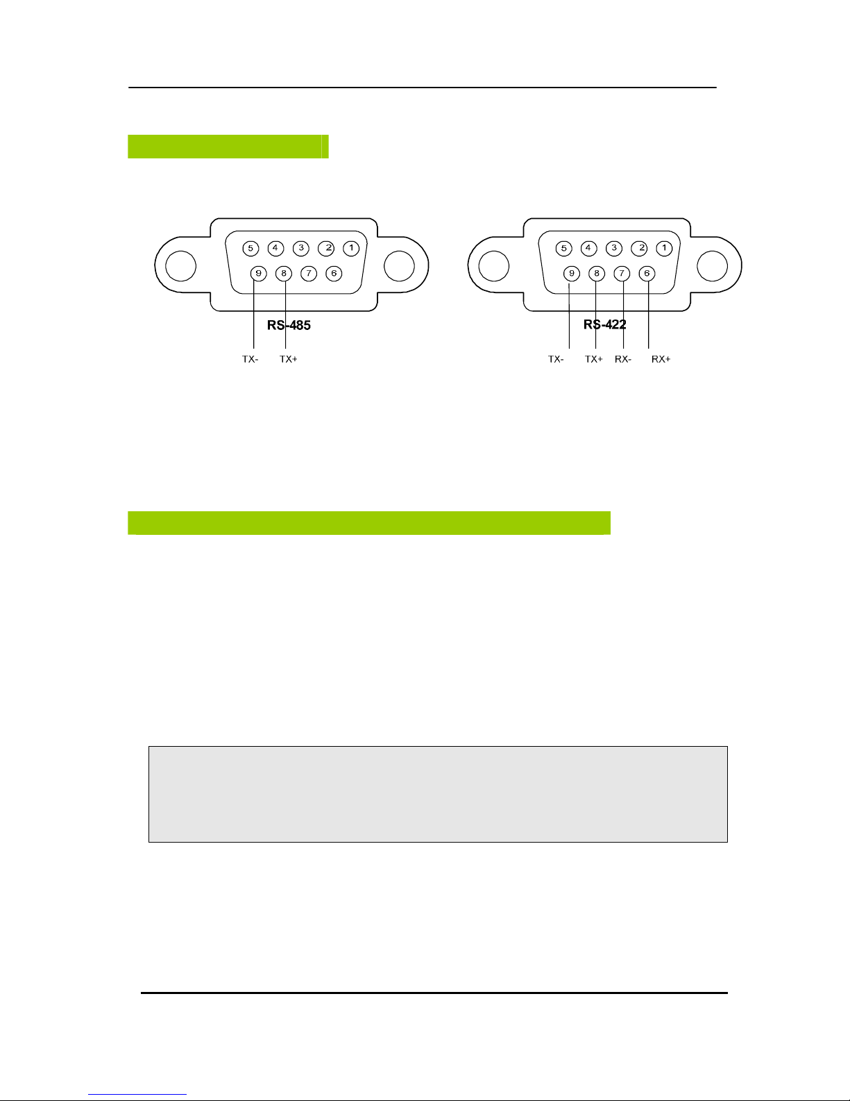
8) RS-485 [D-SUB 9PIN] Connector: For connecting to PTZ camera.
9) RS-232C [D-SUB 9PIN] : For connecting to External Modem.
10) VGA out connector
11) Spot out connector
12) Composite Monitor Output: BNC standard composite video output connector.
13) S-VHS Output: An S-VHS connector for separate luminance and chrominance (Y/C)
signals
14) RJ-45 Ethernet Port: For connecting to remote PC via Ethernet network.
15) USB 2.0 connector: For connecting USB compatible devices.
16) AUDIO Input (1~8, 9~16)/Output (2) connectors: RCA

11 DIGITAL VIDEO RECORDER
Remote Controller
STOP
PLAY
BACK UP
DVR ID
MENU
LOG
FAST FORWARD
DISPLAY MODE
SCHEDULE REC ON/OFF
ENTER
INFORMATION
EXT. SEARCH
REWIND
NUMBERS & ALPHABET
TIME SEARCH
ZOOM
STEP
RECORD
- BUTTON
+ BUTTON
PAN/TILT/ZOOM
12 DIGITAL VIDEO RECORDER
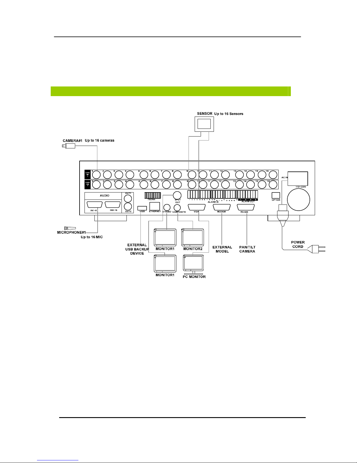
INSTALLATION & CONNECTIONS.
Camera, Monitor, Microphone, Alarm sensor and Power cord.
< Example of 16 ch DVR >
13 DIGITAL VIDEO RECORDER
RXA
RXB
RS-485
SLAVE
IN OUT
ALARM / DVR
-
DVR
++-
RS-232C
-
1 DOME 2
+
DATA2DATA1
J-BOX FRONT
DATA1
DATA2
DC 12V
Rx+Rx-Tx+Tx-
4ALARMINPUT
1 AUX OUTPUT
H
E
A
T
E
R
A
C
2
4
V
A
C
2
4
V
P
O
W
E
R
C
O
M
M
.
(
T
X
+
/
T
X
-
)
V
I
D
E
O
Tx+(DOME1+)
Tx-(DOME1 -)
DOME
CONTROLLER
TXB(TX-)
TXA(TX+)
RS-485
HALF DUPLEX MODE
J-BOX REAR
REAR
AWG # 24
BNC
BNC
MAIN MONITORSPOT MONITOR
KEYBOARD CONTROLLER
BNC
AC 24V
POWER POWER
AC 24V
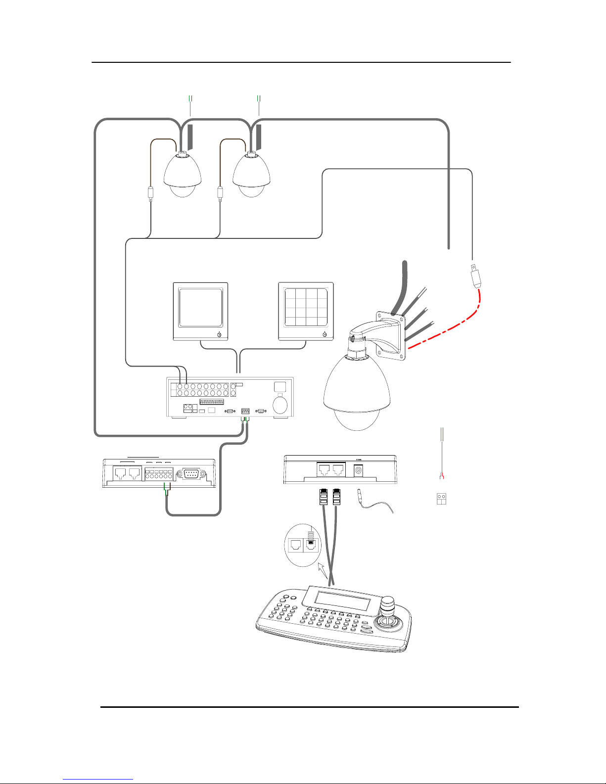
<Single DVR Configuration>
14 DIGITAL VIDEO RECORDER
+
1 DOME 2
-
RS-232C
-++
DVR
- ALARM / DVR
OUTIN
SLAVE
RS-485
Rx+Rx-Tx+Tx- Tx+Tx- Rx+Rx-
Camera 17~12( 15)
Camera 1~16
J-BOX REAR
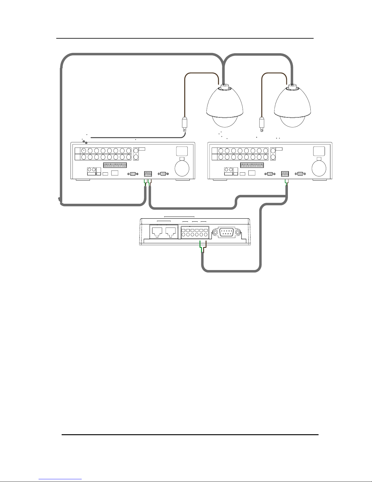
<Single User with 2 DVR Configurations>
15 DIGITAL VIDEO RECORDER
RS-485
SLAVE
IN OUT
ALARM / DVR
-
DVR
++-
J-BOX FRONT
DATA1
RS-232C
DATA2
-
1 DOME 2
+
DC 12V
DATA2DATA1
SW1
FGND AC- AC+
TXBTXARXBRXA
RXA
RXB
TXA
AC+
AC-
TXB
DATA1 DATA2
DC 12V
+
1 DOME 2
-
DATA2
RS-232C
DATA1
J-BOX FRONT
-++
DVR
-
ALARM / DVR
OUTIN
SLAVE
RS-485
Tx+Tx- Rx+Rx-Rx+Rx-Tx+Tx-
TO THE SLAVE CONTROLLER
TO THE NEXT SLAVE CONTROLLER
J-BOX REAR
REAR
SLAVE KEYBOARD CONTROLLER
SPOT MONITOR 2ND MAIN MONITOR
1ST MAIN MONITOR
POWER
AC 24VAC 24V
POWERPOWER
AC 24V
MASTER KEYBOARD CONTROLLER
BNC
AWG # 24
1AUXOUTPUT
4ALARMINPUT
VIDEO
Tx+(DOME1+)
Tx-(DOME1 -)
4ALARMINPUT
1 AUX OUT PUT
REAR
Camera 1~16 Camera 17~12( 15)
J-BOX REAR
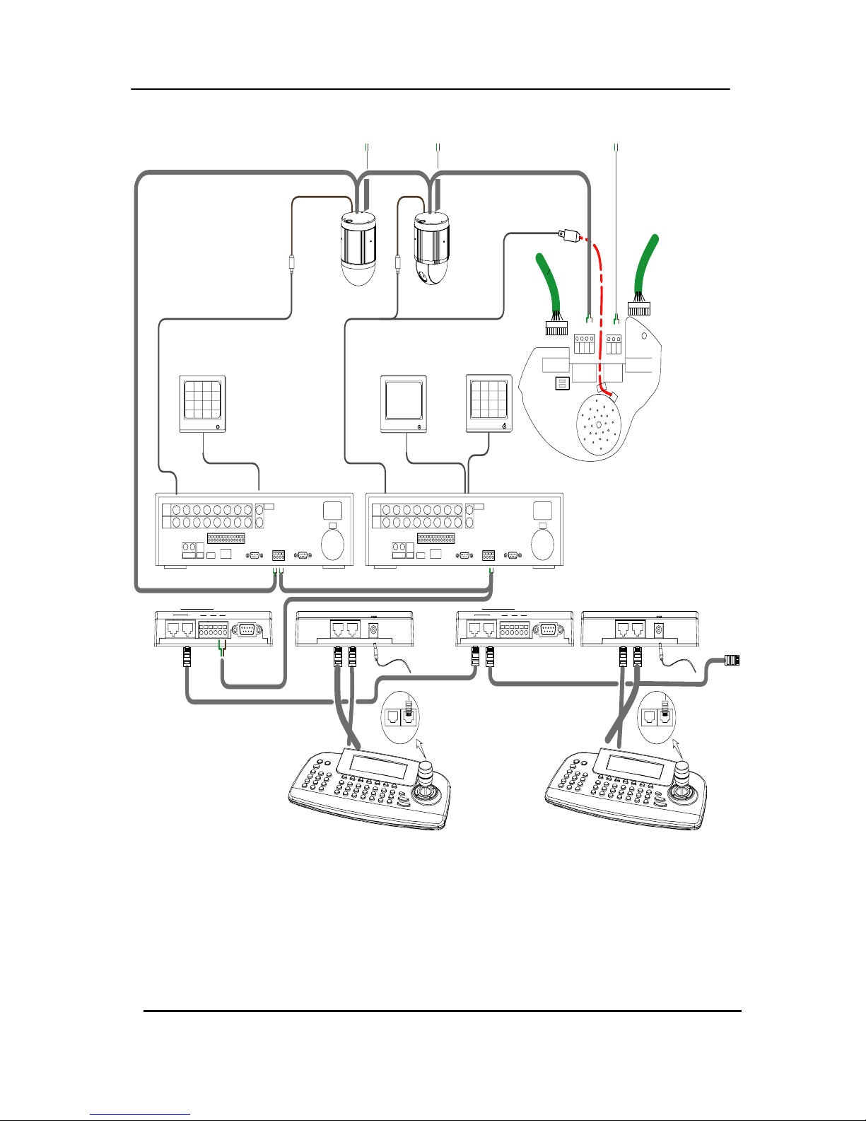
<Multiple Controller Keyboard Configuration>
16 DIGITAL VIDEO RECORDER
PTZ connections.
PC system requirement for Network connection.
(a) 500MHz CPU
(b) 128MB RAM
(c) 4MB Video Card
(d) Windows 98SE, 2000, ME
(e) Spare 10/100-BaseT Ethernet Port
(f) RJ-45 Network Cable
(g) CAT-5 UTP Cable for LAN (Crossover cable for direct connect to PC)
<Disclaimer>
The connection and remote viewing of the DVR may not be successful
on all PC’s due to the variety of PC’s internet connection settings.
Please contact the technical support for further assistance.
17 DIGITAL VIDEO RECORDER
QUICK START PAGE
The Factory Default password for the unit is “000000”
The Default password to run the CMS software is “0”
18 DIGITAL VIDEO RECORDER
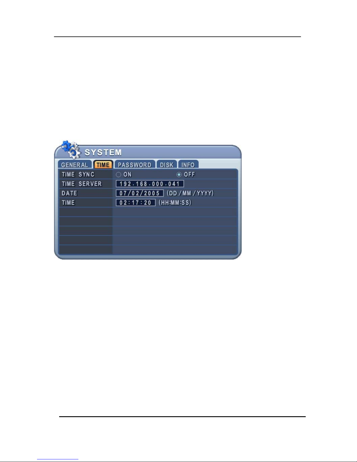
Time & Date Setting
When the DVR is powered on for the very first time, the time and date are set as default to January 1,
2006 Sunday 01:00:00. Before any other operation of the Digital Video Recorder, it is important to
setup the time and the date. Please refer to page 37 for setting the time and the date on the DVR.
Screen Position Adjustment
The screen position is adjustable during live view or playback. Use the directional buttons
to adjust the screen position to best fit the monitor.
19 DIGITAL VIDEO RECORDER
LIVE VIEWING
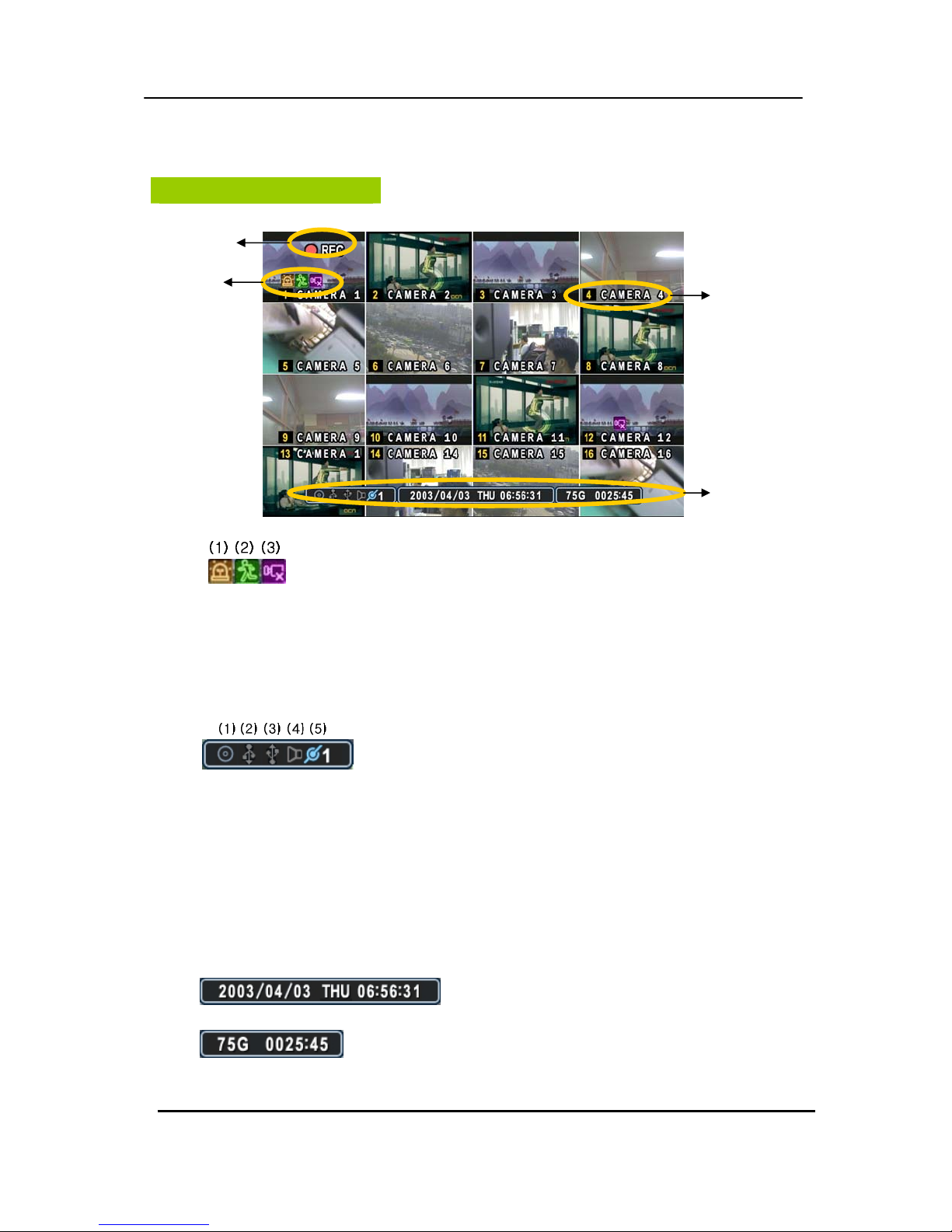
Display Overview
1.
(1) Indicate Alarm In terminal is triggered by an alarm sensor. To disappear, press
[CANCEL] button.
(2) Indicate Motion detected. To disappear, press [CANCEL] button.
(3) Indicate Video Loss during Recording. To disappear, press [CANCEL] button.
2.
(1) Indicate Built-in CD R/W is connected. It’s changed to blue color while it’s doing backup.
(2) Indicate an USB Device is connected on Front panel. It’s changed to blue color while
it’s doing backup.
(3) Indicate an USB Device is connected on Rear panel. It’s changed to blue color while
it’s doing backup.
(4) Indicate Audio Data is stored the selected time during playback and turn to blue color.
(5) It shows Number of Client, which is connected to Network.(MAX:10)
3. : Displays Month, Year, Time and Date.
4. : Displays available HDD space and estimated remaining recording
time.
Recording Mode
Event Indicator
Status
Camera No and Title

20 DIGITAL VIDEO RECORDER
Multiscreen Display and Sequencing
1. Full Screen Display.
Select any camera for Full screen display by pressing the Number button of the
desired camera.
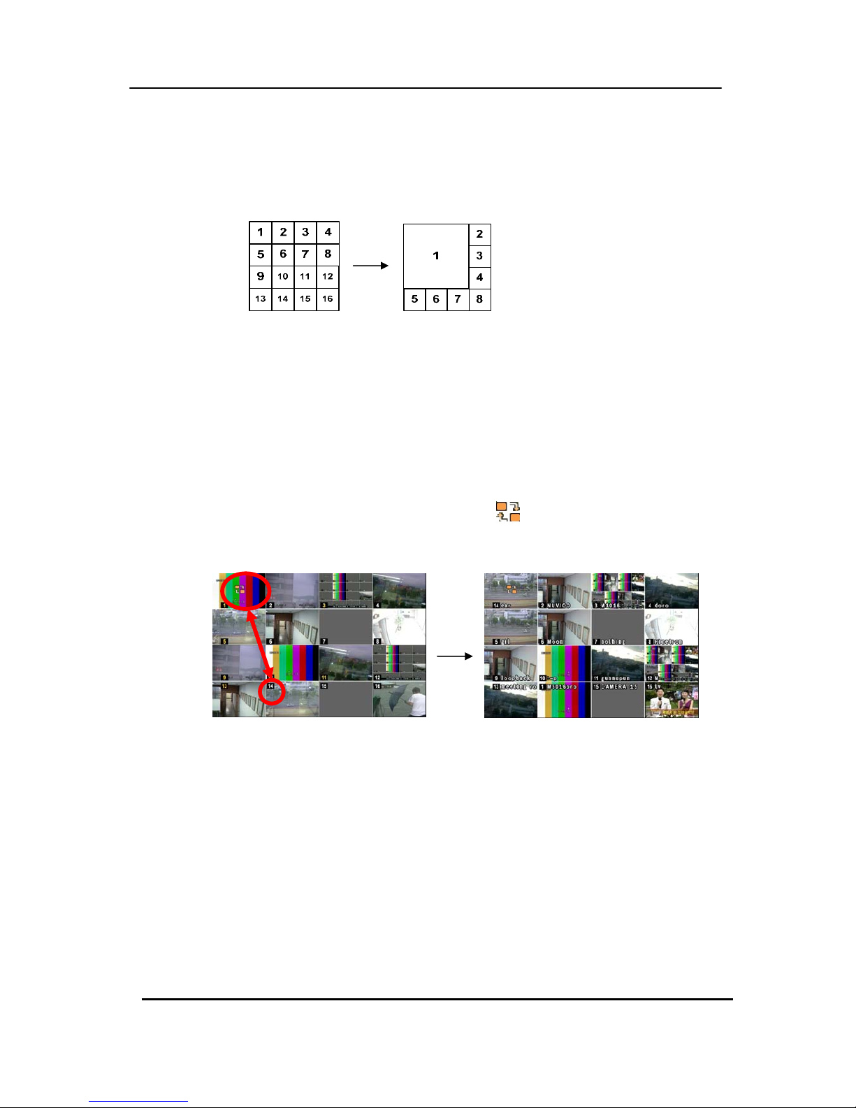
2. Multiscreen Display and Sequencing Display.
Press [DISPLAY] buttons to activate the multiscreen display. It is changed the order
as shown below among your choice of SPLIT MODE. While in 16-way screen display,
press [DISPLAY] buttons for 1second to begin full screen sequencing. The sequence
mode and dwell times are programmable. For detailed information about configuring
those, see “Sequence Setup”. If the sequence mode is not activated, it moves to
Quad mode instead of Sequencing.
21 DIGITAL VIDEO RECORDER
3. Quick button for multi screen Display.
1) Press F1 button on the remote controller + <Number>
For example, press F1 button then number 8.
The eight channel view mode will be displayed.
<Note> 6,4,8,10,13 split mode must be checked on <Spit mode> to use this
function.
2) Repositioning
It is possible to reposition the camera from the bigger window with the one from a
smaller one. It is used on 6,7,8,9,10, 13,16 split mode
① Press F2 button on the remote controller.
Mark will be displayed.
② Press Numeric button you wish to switching display.
③ Press [Enter] button to exit here with saving changes.
Press [Cancel] to exit without change.
Press [Menu] button to rearrange.
22 DIGITAL VIDEO RECORDER
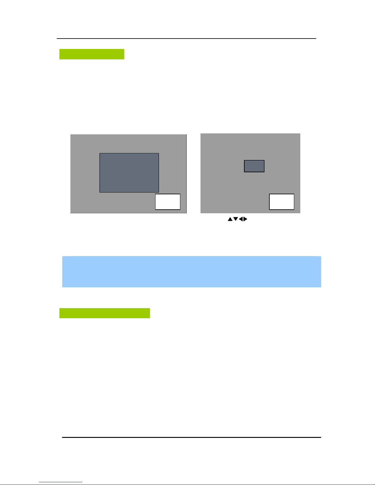
Zooming
During live view mode or playback, it is possible to zoom into a section of the screen to get a
close-up view of the screen.
1. To activate the digital zoom, select the full screen display of the camera you wish to
zoom.
2. Then press the [ZOOM] button. Zoom area box pops up, as shown below.
3. Move the box to the desired position using Direction [
] buttons.
4. Press [+] button to enlarge the image. Press [ - ] button to zoom out the image.
5. Press [CANCEL] button to return normal mode.
<Note>
If the Zoom button is pressed while in a multiscreen display, zoom operation is not
activated.
Spot Monitor
In addition to the Main Monitor, attaching a Spot Monitor enables user to monitor specific
channels independently form the main monitor
y Press [Spot] button on the remote controller or Shuttle hold button on front, then press
number button you wish watch as full screen.
y Press [Spot] button twice to auto switch cameras. Sequence interval can be set from the
Sequential Setup.
y When an alarm has been triggered, that specific channel will go into Full Screen.
x 2 x 8
23 DIGITAL VIDEO RECORDER
OPERATION
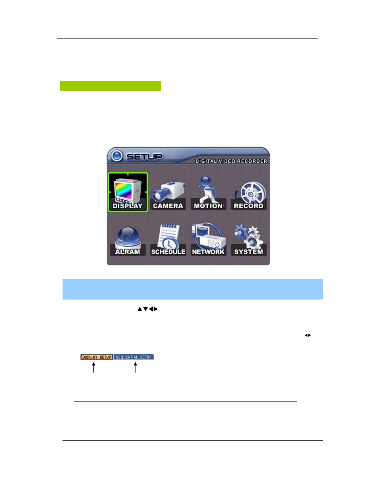
Main Menu Overview
When the DVR is powered on, Live Viewing screen will appear after initialization about 30sec.
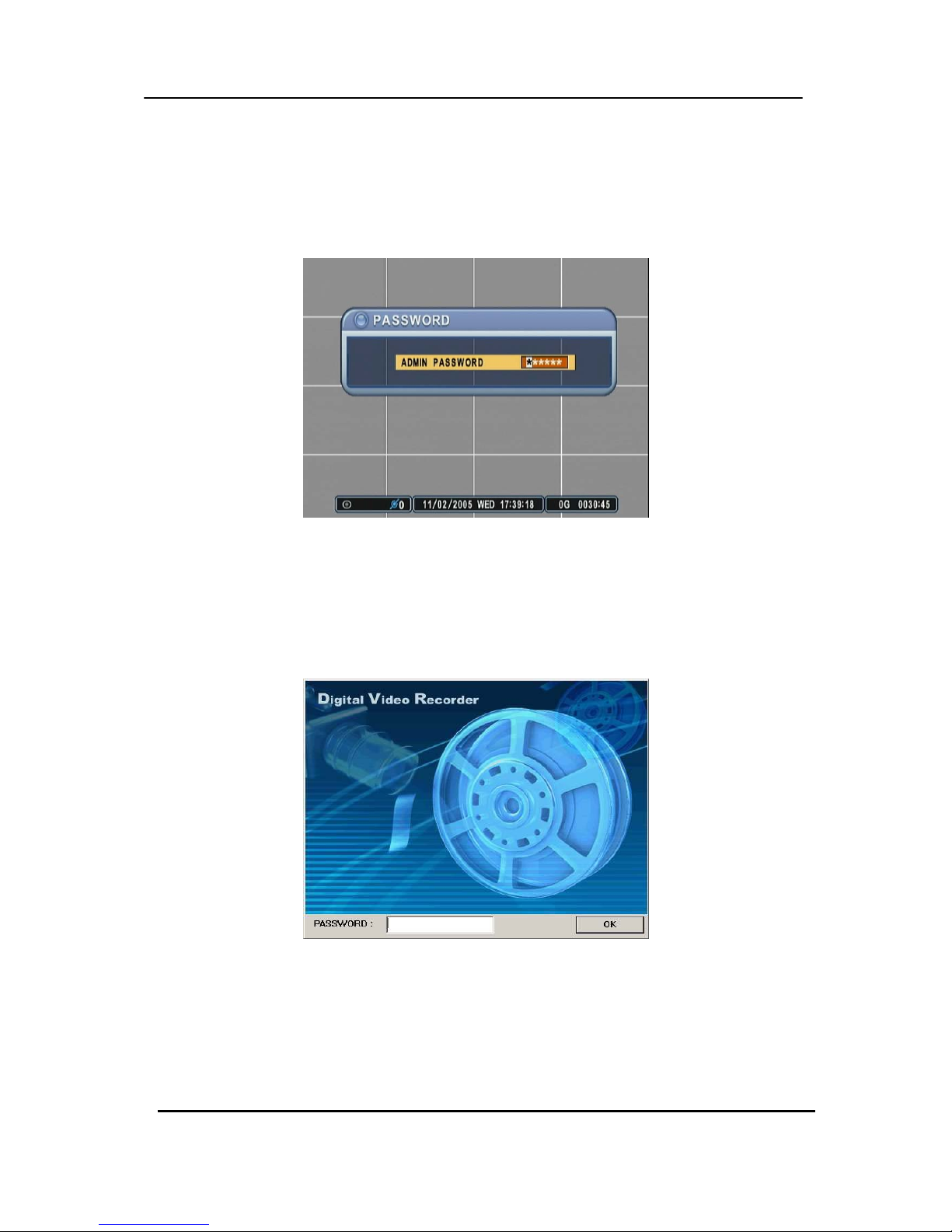
Press [MENU] button to access the main menu. An Admin Password Box will appear. Enter
the password using Numeric buttons. Default password is ‘000000’. Main Menu appears after
proper password entered, shown as below.
<Note> Factory default Admin/user password is [000000]. It is recommended to change the
“PASSWORD” when you install the DVR. Refer to [System Setup].
1.
Use Direction buttons [ ] to select the desired menu. Items selected in the menu are
represented in color.
2. Press [ENTER] button to select the menu and display Sub-Menu. Use Left/ Right buttons [
] to
select on TAP menu.
Selected items changed into [ORANGE] color.
* It is automatically saved changes when you move between TAP menus.
3. Press [CANCEL] to exit a menu without changes.
Press [ENTER] button to exit a menu with saving changes.
Selected Not selected
24 DIGITAL VIDEO RECORDER
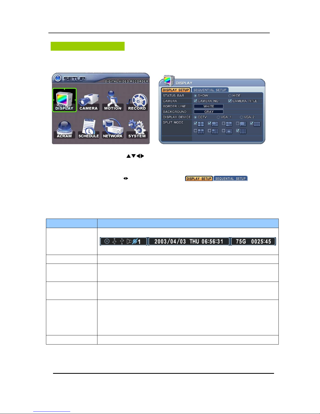
Display Option
1. DISPLAY SETUP
1. Use Direction buttons [ ] to select “DISPLAY” menu. Then, press [ENTER] button
to display “DISPLAY SETUP”.
2. Use Left/Right buttons [
] to select on TAP menu ( ). Selected
items changed [ORANGE] color..
3. Use Down [T] button to specify.
4. Use [-, +] button to change the values
ITEM ADJUSTMENT
STATUS BAR
y Select “Show” or “Hide” below status bar on Main Monitor.
CAMERA
y Select On-Screen-Display information for Camera Number and Title.
BORDER LINE
y Select Board Line between cameras.
[WHITE Æ GRAY Æ DARK GRAY Æ BLACK]
BACKGROUND
y Select Background color on NO VIDEO status.
[GRAY Æ DARK GRAY Æ BLACK Æ BLUE Æ WHITE]
DISPLAY DEVICE
ySelect On-Screen-Display coordinates on Monitor.
- CCTV Monitor: Video out through Composite and VGA
- VGA 1 Monitor: Video out through VGA only. Specific resolution for this DVR.
- VGA 2 Monitor: Video out through VGA only. 800*600 resolutions.
SPLIT MODE y Select Split mode while for manual switching
5. Save changes and exit the menu, press [ENTER] button.
Exit the menu without making changes, press [CANCEL] button.
25 DIGITAL VIDEO RECORDER
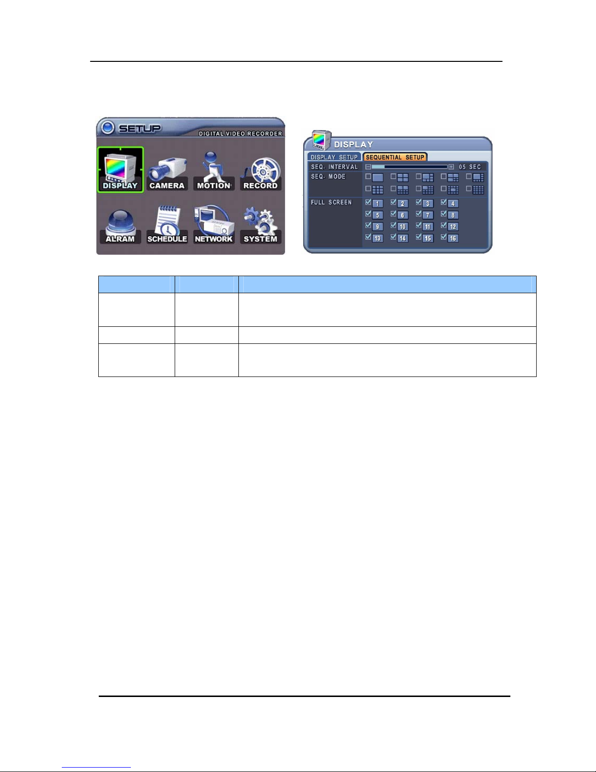
2. SEQUENTIAL SETUP (Auto Sequence)
ITEM DEFAULT ADJUSTMENT
SEQ.
INTERVAL
5 Sec y Specify the dwell time of each camera or Muliscreen mode is
displayed. Use [-, +] button : [1 second ~ 30 second]
SEQ. MODE None y Select desired sequence mode to switching.
FULL SCREEN
ALL y Select the cameras to be included or excluded from the automatic
sequencing.
26 DIGITAL VIDEO RECORDER
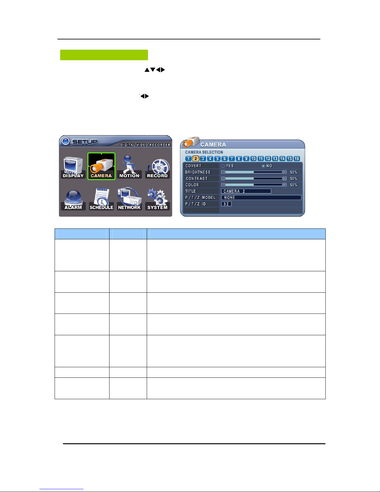
Camera Setup
1. Use Direction buttons [ ] to select “CAMERA” menu. Then, press [ENTER] button to
display “CAMERA”.
2. Use Left/Right buttons [
] or Number button to select the Camera you wish to configure.
3. Use Down [T] button to move specified menu and use Left/Right buttons [WX] to
select other item.
4. Use [-, +] button to change the value.
ITEM DEFAULT ADJUSTMENT
COVERT
No y If the Covert Mode is “YES”. Selected camera is invisible from
all live displays, playback and Network while continuing to record.
Covert cameras are viewable after change into “NO” .
BRIGHTNESS
50% y The brightness of each camera can be adjusted by pressing [-,+]
buttons.
CONTRAST
50% y The contrast of each camera can be adjusted by pressing [-,+]
buttons.
COLOR
50% y The color of each camera can be adjusted by pressing [-,+]
buttons.
CAMERA TITLE
None y A combination of 12 digits and alphabets can be entered to label
each camera. Press appropriate Numeric button to type camera
title. It’s up to 12 characters. See Next chart.
P/T/Z MODEL None y Select P/TZ camera model to control.
P/T/Z ID
Camera No y Select appropriated channel for the PTZ camera. Camera ID
means Camera address.
5. Save changes and exit the menu, press [ENTER] button.
Exit the menu without making changes, press [CANCEL] button.
27 DIGITAL VIDEO RECORDER
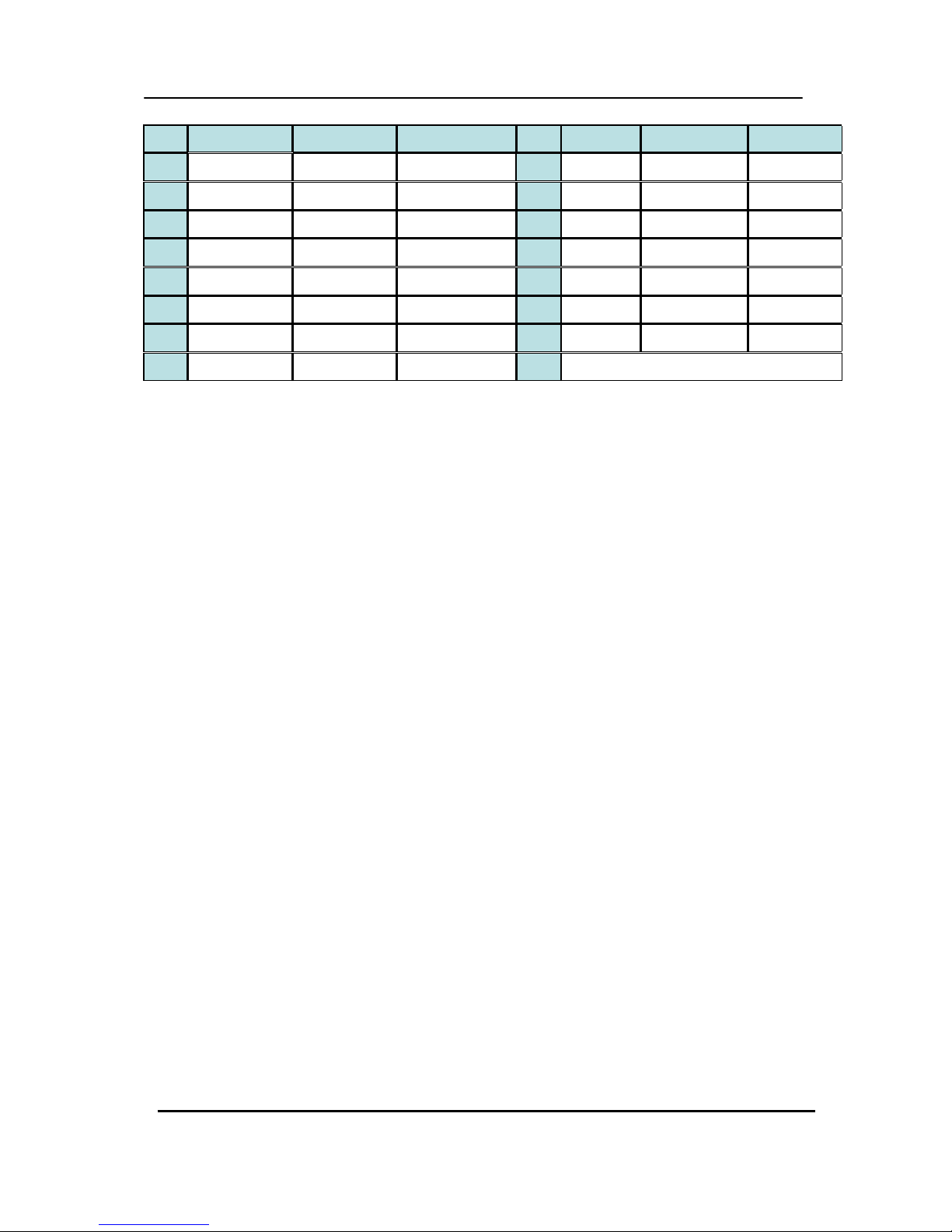
No 1st Press 2nd Press 3rd Press No 1st 2nd 3rd
1 A B 1 9 Q R 9
2 C D 2 10/0 S T 10
3 E F 3 11 U V 11
4 G H 4 12 W X
5 I J 5 13 Y Z
6 K L 6 14 . @
7 M N 7 15 - _
8 O P 8 16 SPACE
<Number button to insert characters >
28 DIGITAL VIDEO RECORDER
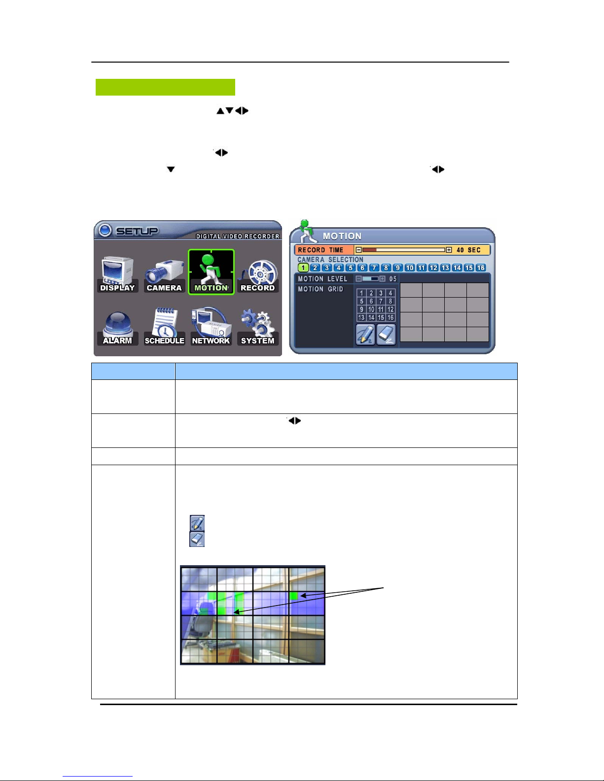
Motion Recording
1. Use Direction buttons [ ] to select “MOTION” menu. Then, press [ENTER] button to
display “MOTION”.
2. Use Left/Right buttons [
] or Number button to select the Camera you wish to configure.
3. Use Down [
] button to move specified menu and use Left/Right buttons [ ] to select other
item.
4. Use [-, +] button to change the value.
ITEM ADJUSTMENT
RECORD TIME
y Determines the duration of recording when motion is detected.
[20SEC ~ 240SEC]
CAMERA
SECTION
y Use Left/Right buttons [
] or Number button to select the Camera you wish
to configure.
MOTION LEVEL y Level 1: Low sensitivity~ Level 20: High sensitivity.
MOTION GRID
y Use this menu to setup Zones for the motion detection The screen shown
below will overlay the current video image.
y It is divided into 16 Grid and selected by Number button.
y : Select All.
y : : Clear All.
y Motion detected zones will be changed to GREEN Color.
y It is also possible to select smaller motion grids for more precise motion
detection by using CMS.
Motion Detected zones

29 DIGITAL VIDEO RECORDER
5. Save changes and exit the menu, press [ENTER] button. Then go “RECORD” Menu.
6. Select “ON” or “OFF” to Enable or Disable motion detection on a per camera, as
shown below.
7.
Press the REC button, then Motion recording starts according to configured Recording
Quality, Frame Rate when Motion detected. It will be back to stand-by mode after
motion recording time is end. Camera does not record under normal conditions.
<Note> Motion Duration will be extended if there is another motion detection while
motion recording.
<Note> There may be cases when the recorder’s built-in motion detection function
does not operate properly due to the condition of the input video signal or
other factors.
<Note> It is recommended selection of at least 3 motion blocks to get more accurate
motion recording.
 Loading...