

Page 1

D4267042B
DU Series
Thank you for purchasing our product.
Before using this CMOS camera, please read through this instruction manual
carefully in order to use this product correctly and safely.
After reading, keep this instruction manual handy so that you can refer to,
whenever you need it.
CMOS Camera
Instruction Manual
Model
B/W Camera : DU1207MG
Color Camera : DU1207MCG / DU1207MCF
Information contained in this document is subject to change without prior notice.
Standard name might be trade mark of each company.
Copyright © 2017 TOSHIBA TELI CORPORATION, All rights reserved. http://www.toshiba-teli.co.jp/en/
Page 2

D4267042B
Contents
Contents ................................................................................................................................................. 1
Safety Precautions ................................................................................................................................. 3
General Handing ............................................................................................................................ 4
CASES FOR INDEMNITY (LIMITED WARRANTY) ...................................................................... 6
RESTRICTION FOR USE .............................................................................................................. 7
Notes on using this product ............................................................................................................ 8
Installation ............................................................................................................................................ 12
Specifications ....................................................................................................................................... 13
Overview ....................................................................................................................................... 13
Features ........................................................................................................................................ 13
Configuration ................................................................................................................................ 15
Connection .................................................................................................................................... 16
Connector Pin Assignment ........................................................................................................... 17
Outline Drawing ............................................................................................................................ 18
General Specifications .................................................................................................................. 19
LED Status .................................................................................................................................... 22
I/O Specification ............................................................................................................................ 23
Timing Specification ...................................................................................................................... 27
Typical Spectral Response ........................................................................................................... 29
Operating Ambient Conditions ...................................................................................................... 31
Functions .............................................................................................................................................. 33
Bootstrap Registers ...................................................................................................................... 35
DeviceControl ............................................................................................................................... 37
ImageFormatControl ..................................................................................................................... 38
Scalable ........................................................................................................................................ 42
Binning .......................................................................................................................................... 47
Decimation .................................................................................................................................... 52
Reverse ........................................................................................................................................ 57
PixelFormat ................................................................................................................................... 60
BayerProcessingMode ................................................................................................................. 66
TestPattern .................................................................................................................................... 69
AcquisitionControl ......................................................................................................................... 73
ImageBuffer .................................................................................................................................. 79
TriggerControl ............................................................................................................................... 84
ExposureTime ............................................................................................................................... 94
DigitalIOControl ............................................................................................................................ 98
AntiGlitch / AntiChattering........................................................................................................... 108
TimerControl ............................................................................................................................... 112
Gain ............................................................................................................................................ 117
BlackLevel .................................................................................................................................. 120
Gamma ....................................................................................................................................... 122
Hue/Saturation ............................................................................................................................ 124
Sharpness ................................................................................................................................... 128
BalanceRatio .............................................................................................................................. 130
ColorCorrectionMatrix ................................................................................................................. 135
ALCControl ................................................................................................................................. 139
LUTControl ................................................................................................................................. 143
UserSetControl ........................................................................................................................... 146
EventControl ............................................................................................................................... 151
FrameSynchronization ................................................................................................................ 154
LEDIndicatorLuminance ............................................................................................................. 156
DPCControl ................................................................................................................................. 158
Chunk.......................................................................................................................................... 162
SequentialShutterControl ........................................................................................................... 168
Appendix ............................................................................................................................................ 173
1 / 179
Copyright © 2017 TOSHIBA TELI CORPORATION, All rights reserved. http://www.toshiba-teli.co.jp/en/
Page 3

D4267042B
UserSetSave and UserSetQuickSave difference ....................................................................... 173
MultiFrame and Bulk function difference .................................................................................... 175
Warranty rules .................................................................................................................................... 178
Repair ................................................................................................................................................. 179
2 / 179
Copyright © 2017 TOSHIBA TELI CORPORATION, All rights reserved. http://www.toshiba-teli.co.jp/en/
Page 4
D4267042B
Safety Signs
Description
WARNING
Indicates a potentially hazardous situation that may result in death or serious
injury (*1) in the event of improper handling.
CAUTION
Indicates a potentially hazardous situation that may result in light to moderate
injuries (*2) or only in property damage (*3)in the event of improper handling.
Safety Symbols
Description
PROHIBITED
This sign indicates PROHIBITION (Do not).
The content of prohibition is shown by a picture or words beside the symbol.
MANDATORY
This sign indicates MANDATORY ACTION (You are required to do).
The content of action is shown by a picture or words beside the symbol.
Safety Precautions
Before using this product, read these safety precautions carefully. Important information is shown in this
Instruction Manual to protect users from bodily injuries and property damages, and to enable them to use the
product safely and correctly.
Please be sure to thoroughly understand the meanings of the following signs and symbols before reading the
main text that follow, and observe the instructions given herein.
[Definition of Safety Signs]
Notes *1:“Serious injury” refers to cases of loss of eyesight, wounds, burns (high or low temperature),
electric shock, broken bones, poisoning, etc., which leave after-effects or which require
hospitalization or a long period of outpatient treatment of cure.
*2: "Light to moderate injuries" refers to injuries, burns, electric shock etc. that do not require
hospitalization or long-term treatment.
*3: "Property damage" refers to cases of extensive damage involving damage to buildings,
equipment, farm animals, pet animals and other belongings.
[Explanation of Safety Symbols]
Copyright © 2017 TOSHIBA TELI CORPORATION, All rights reserved. http://www.toshiba-teli.co.jp/en/
3 / 179
Page 5
D4267042B
WARNING
Stop operation immediately when any abnormality or defect occurs.
If abnormal conditions are present, such as smoke, a burning smell, ingress of water or
foreign matter, or if the equipment is dropped or malfunctions, fire or electric shock may
result.
Be always sure to disconnect the power cable from the wall socket at once and contact
your dealer.
Unplug
Do not use the equipment in locations subject to water splashes.
Otherwise, fire or electric shock may result.
Do not get wet
Do not disassemble, repair, or modify the equipment.
Otherwise, fire or electric shock may result.
For internal repair, inspection, or cleaning, contact your sales representative.
Never pull apart
Do not place anything on the equipment.
If metallic objects, liquid, or other foreign matter enters the equipment, fire or electric
shock may result.
Avoid
Do not install the equipment in an unstable or inclined location or locations
subject to vibration or impact.
Otherwise, the equipment may topple over and cause personal injury.
Avoid
During an electrical storm, do not touch the power cable and the connection
cable.
Otherwise, an electric shock may result.
Do not touch
Instruction
Use the specified voltage.
Use of an unspecified voltage may result in fire or electric shock.
Do not be handled roughly, damaged, fabricated, bent forcefully, pulled, twisted,
bundled, placed under heavy objects or heated the power cable and the
connection cable.
Otherwise, fire or electric shock may result.
Avoid
General Handing
Copyright © 2017 TOSHIBA TELI CORPORATION, All rights reserved. http://www.toshiba-teli.co.jp/en/
4 / 179
Page 6
D4267042B
CAUTION
Observe the following when installing the equipment:
·Do not cover the equipment with a cloth, etc.
·Do not place the equipment in a narrow location where heat is likely to accumulate.
Otherwise, heat will accumulate inside the equipment, possibly resulting in a fire.
Instruction
Do not place the equipment in locations subject to high moisture, oil fumes,
steam, or dust.
Otherwise, fire or electric shock may result.
Avoid
Do not install the equipment in locations exposed to direct sunlight or humidity.
Otherwise, the internal temperature of the equipment will rise, which may cause a fire.
Avoid
Use only specified the power cable and the connection cables.
Otherwise, fire or electric shock may result.
Instruction
Do not give strong impact against the equipment.
It may cause the trouble.
Avoid
When performing connection, turn off power.
When connecting the power cable and the connection cable, turn off the equipment
power.
Otherwise, fire or electric shock may result.
Instruction
Do not expose its camera head to any intensive light (such as direct sunlight).
Otherwise, its inner image pickup device might get damaged.
Avoid
Avoid short-circuiting signal output.
Otherwise, a malfunction may occur.
Avoid
Avoid giving a strong shock against the camera body.
It might cause a breakdown or damage. If your camera is used in a system where its
connector is subjected to strong repetitive shocks, its connector is possible to break
down. If you intend to use your camera in such a situation, if possible, bundle and fix a
cable in the place near the camera, and do not transmit a shock to the connector.
Avoid
Contact your sales representative to request periodic inspection and cleaning
(every approx five years).
Accumulation of dust inside the equipment may result in fire or electric shock.
For inspection and cleaning costs, contact your sales representative.
Instruction
Copyright © 2017 TOSHIBA TELI CORPORATION, All rights reserved. http://www.toshiba-teli.co.jp/en/
5 / 179
Page 7

D4267042B
CASES FOR INDEMNITY (LIMITED WARRANTY)
We shall be exempted from taking responsibility and held harmless for damage or losses incurred by the user
in the following cases.
● In the case damage or losses are caused by natural disasters, such as an earthquake and thunder, fire, or
other acts of God, acts by a third party, deliberate or accidental misuse by the user, or use under extreme
operating conditions.
● In the case of indirect, additional, consequential damages (loss of business interests, suspension of
business activities) are incurred as result of malfunction or non-function of the equipment, we shall be
exempted from responsibility for such damages.
● In the case damage or losses are caused by failure to observe the information contained in the
instructions in this instruction manual and specifications.
● In the case damage or losses are caused by use contrary to the instructions in this instruction manual and
specifications.
● In the case damage or losses are caused by malfunction or other problems resulting from unintended use
of equipment or software etc. that are not specified.
● In the case damage or losses are caused by repair or modification conducted by the customer or any
unauthorized third party (such as an unauthorized service representative).
● Expenses we bear on this product shall be limited to the individual price of the product.
● The item that is not described in specifications of this product is out of the guarantee.
● The case of damages or losses which are caused by incorrect connection of the cable is out of the
guarantee.
6 / 179
Copyright © 2017 TOSHIBA TELI CORPORATION, All rights reserved. http://www.toshiba-teli.co.jp/en/
Page 8

D4267042B
RESTRICTION FOR USE
● Should the equipment be used in the following conditions or environments, give consideration to safety
measures and inform us of such usage:
1. Use of the equipment in the conditions or environment contrary to those specified, or use outdoors.
2. Use of the equipment in applications expected to cause potential hazard to people or property, which
require special safety measures to be adopted.
● This product can be used under diverse operating conditions. Determination of applicability of equipment or
devices concerned shall be determined after analysis or testing as necessary by the designer of such
equipment or devices, or personnel related to the specifications. Such designer or personnel shall assure
the performance and safety of the equipment or devices.
● This product is not designed or manufactured to be used for control of equipment directly concerned with
human life (*1) or equipment relating to maintenance of public services/functions involving factors of safety
(*2). Therefore, the product shall not be used for such applications.
(*1): Equipment directly concerned with human life refers to.
- Medical equipment such as life-support systems, equipment for operating theaters.
- Exhaust control equipment for exhaust gases such as toxic fumes or smoke.
- Equipment mandatory to be installed by various laws and regulations such as the Fire Act or Building
Standard Law
- Equipment related to the above
(*2): Equipment relating to maintenance of public services/functions involving factors of safety refers to.
- Traffic control systems for air transportation, railways, roads, or marine transportation
- Equipment for nuclear power generation
- Equipment related to the above
7 / 179
Copyright © 2017 TOSHIBA TELI CORPORATION, All rights reserved. http://www.toshiba-teli.co.jp/en/
Page 9

D4267042B
10mm or less
C-mount lens
Bottom of
the screw
8mm or less
Notes on using this product
● Handle carefully
Do not drop the equipment or allow it to be subject to strong impact or vibration, as such action may cause
malfunctions. Further, do not damage the connection cable, since this may cause wire breakage.
● Environmental operating conditions
Do not use the product in locations where the ambient temperature or humidity exceeds the specifications.
Otherwise, image quality may be degraded or internal components may be adversely affected. In particular,
do not use the product in areas exposed to direct sunlight. Moreover, during shooting under high
temperatures, vertical stripes or white spots (noise) may be produced, depending on the subject or camera
conditions (such as increased gain). However, such phenomena are not malfunctions.
● Check a combination with the lens
Depending on the lens and lighting you use, an image is reflected as a ghost in the imaging area. However,
this is not because of a fault of the camera.
In addition, depending on the lens you use, the performance of the camera may not be brought out fully due
to deterioration in resolution and brightness in the peripheral area, aberration and others.
Be sure to check a combination with the camera by using the lens and lightning you actually use.
When installing a lens in the camera, make sure carefully that it is not tilted.
In addition, use a mounting screw free from defects and dirt. Otherwise, the camera may be unable to be
removed.
Install a next lens; its dimension of protrusion from bottom of the screw is equal to or less than 8 mm. If a
lens does not stand to this condition, it might not be installed to this camera.
● Mounting to pedestal
Copyright © 2017 TOSHIBA TELI CORPORATION, All rights reserved. http://www.toshiba-teli.co.jp/en/
When mounting this product to a pedestal, make sure carefully that lens doesn’t touch with the pedestal.
8 / 179
Page 10

D4267042B
● Do not expose the camera's image-pickup-plane to sunlight or other intense light directly
Its inner CMOS sensor might be damaged.
● Occurrence of moiré
If you shoot thin stripe patterns, moiré patterns (interference fringes) may appear. This is not a malfunction.
● Occurrence of noise on the screen
If an intense magnetic or electromagnetic field is generated near the camera or connection cable, noise may
be generated on the screen. If this occurs, move the camera or the cable.
● Handling of the protective cap
If the camera is not in use, attach the lens cap to the camera to protect the image pickup surface.
● If the equipment is not to be used for a long duration
Turn off power to the camera for safety.
● Maintenance
Turn off power to the equipment and wipe it with a dry cloth.
If it becomes severely contaminated, gently wipe the affected areas with a soft cloth dampened with diluted
neutral detergent. Never use alcohol, benzene, thinner, or other chemicals because such chemicals may
damage or discolor the paint and indications.
If the image pickup surface becomes dusty, contaminated, or scratched, consult your sales representative.
9 / 179
Copyright © 2017 TOSHIBA TELI CORPORATION, All rights reserved. http://www.toshiba-teli.co.jp/en/
Page 11
D4267042B
Following information is only for EU-member states:
The use of the symbol indicates that this product may not be treated as household waste. By
ensuring this product is disposed of correctly, you will help prevent potential negative
consequences for the environment and human health, which could otherwise be caused by
inappropriate waste handling of this product. For more detailed information about the take-back
and recycling of this product, please contact your supplier where you purchased the product.
“This symbol is applicable for EU member states only”
This equipment has been tested and found to comply with the limits for a class A digital device,
pursuant to Part 15 of the FCC Rules.
These limits are designed to provide reasonable protection against harmful interference when the
equipment is operated in a commercial environment.
This equipment generates, uses, and can radiate radio frequency energy and, if not installed and
used in accordance with the instruction manual, may cause harmful interference to radio
communication.
Operation of this equipment in a residential area is likely to cause harmful interference in which case
the user will be required to correct the interference at his own expense.
Defective pixels
A CMOS image sensor is composed of photo sensor pixels in a square grid array. Due to
the characteristics of CMOS image sensors, over- or under-driving of the pixels results in
temporary white or black areas (as if these are noises) appearing on the screen. This
phenomenon which is not a defect is exacerbated under higher temperatures and long
exposure time.
Image shading
The brightness of the upper part of the screen may be different from that of the lower part. Note
that this is a characteristic of a CMOS image sensor and is not a fault.
● Disposal
When disposing of the camera, it may be necessary to disassemble it into separate parts, in accordance with
the laws and regulations of your country and/or municipality concerning environmental contamination.
[Phenomena specific to CMOS sensor]
Copyright © 2017 TOSHIBA TELI CORPORATION, All rights reserved. http://www.toshiba-teli.co.jp/en/
10 / 179
Page 12
D4267042B
环保使用期限标识,是根据电子信息产品污染控制管理办法以及,电子
信息产品污染控制标识要求(SJ/T11364-2014)、电子信息产品环保使用
期限通则,制定的适用于中国境内销售的电子信息产品的标识。
电子信息产品只要按照安全及使用说明内容,正常使用情况下,从生产
月期算起,在此期限内,产品中含有的有毒有害物质不致发生外泄或突
变,不致对环境造成严重污染或对其人身、财产造成严重损害。
产品正常使用后,要废弃在环保使用年限内或者刚到年限的产品时,请
根据国家标准采取适当的方法进行处置。
另外,此期限不同于质量/功能的保证期限。
The Mark and Information are applicable for People's Republic of
China only.
部件名称
有毒有害物质或元素
铅(Pb)
汞(Hg)
镉(Cd)
六价铬
(Cr(VI))
多溴联苯
(PBB)
多溴二苯醚
(PBDE)
相机本体
× ○ ○ ○ ○
○
本表格依据SJ/T 11364的规定编制
○:表示该有毒有害物质在该部件所有均质材料中的含量均在电子信息产品中有毒有害物质的
限量要求标准规定的限量要求(GB/T26572)以下
×:表示该有毒有害物质至少在该部件的某一均质材料中的含量超出电子信息产品中有毒有害
物质的限量要求标准规定的限量要求(GB/T26572)
This information is applicable for People's Republic of China only.
中华人民共和国
环保使用期限
ペーパーボード
纸板
Paper board
箱/箱子/Box
内部緩衝材料・袋
内部缓冲材料·袋
Internal buffer materials・Bag
10
<产品中有毒有害物质或元素的名称及含量>
リサイクルに関する情報(包装物)
有关再利用的信息(包装物)
Information on recycling of wrapping composition
Copyright © 2017 TOSHIBA TELI CORPORATION, All rights reserved. http://www.toshiba-teli.co.jp/en/
11 / 179
Page 13

D4267042B
Installation
Before using this product, you shall install application software to display image and control registers of
camera, and IP configuration tool for network setting.
You can download the SDK for our USB camera products (TeliCamSDK) from the Service & Support section
of our website.
User registration is necessary to use downloading service. Please make a user registration, or contact your
sales representative.
● TOSHIBA TELI CORPORATION Top Page
http://www.toshiba-teli.co.jp/en/
● Service & Support
https://www.toshiba-teli.co.jp/cgi/ss/en/service.cgi
Please refer to the TeliCamSDK startup guide, about Operation environment, Installation, and Setup.
12 / 179
Copyright © 2017 TOSHIBA TELI CORPORATION, All rights reserved. http://www.toshiba-teli.co.jp/en/
Page 14

D4267042B
Specifications
Overview
DU1207M series is an integrated-(one-body)-type camera that adopts a global shutter CMOS sensor. These
are DU1207MG (12M type1.1). Suffix [C] are attached to the color models. For video output and camera
control, the USB 3.0 interface standard is adopted for high transfer rate, and it is easy to integrate into
industrial equipment.
Features
● High frame rate
Supporting high frame rate, DU1207MG 32fps (Mono8), DU1207MCG/MCF 31fps (Bayer8).
● Global shutter
As it employs a global electronic shutter similar to a CCD image sensor, clear images of even fast-moving
object are obtainable with less blur.
● USB*3.0 interface
Video output and camera control are performed via the USB 3.0 standard interface. Data transfer is up to
5Gbps (Maximum) that enables to output uncompressed video data at high frame rate.
● USB3 Vision*
This product is based on USB3 Vision Ver.1.0.
● GenICam* Ver 2.3
This product is based on GenICam Generic Interface for Cameras Ver 2.3.
● IIDC2* Digital Camera Control Specification Ver.1.1.0
This product is based on IIDC2 Digital Camera Control Specification Ver.1.1.0.
13 / 179
Copyright © 2017 TOSHIBA TELI CORPORATION, All rights reserved. http://www.toshiba-teli.co.jp/en/
Page 15

D4267042B
● e-CON* Connector adoption
The e-CON connector adoption enables to assemble the cable easily without using special tools.
● Random Trigger Shutter
The Random Trigger Shutter function provides images in any timing by input of an external trigger signal.
Trigger control from PC is available as well.
● Scalable
Selectable video output area. This mode achieves higher frame rate by reducing vertical output area. And
reduces occupied data rate of USB bus by reducing horizontal output area.
● Binning
Pixel data is combined by vertical and horizontal. It achieves high frame rate.
● Decimation
Camera reads all effective areas at high speed by skipping lines.
● Color processing
Color models have built in color processing.
There are RGB, BGR, YUV 4:2:2, YUV 4:1:1, Bayer and Mono output modes. In addition, it produced an
image with restrained false color by adaptive filter interpolating 7 x 7 pixels.
●Dust-proof Glass
Dust-proof Glass is built in default.
Suffix [G] is attached to the model name of built-in Glass.
● IR-cut filter
Build-in IR-cut filter models are optional for color models.
Suffix [F] is attached to the model name of built-in IR-cut filter model.
● EU RoHS & Chinese ROHS
* USB is a unified standard established by USB-IF(USB Implementers Forum).
* USB3 Vision is a unified standard established by AIA (Automated Imaging Association).
* GeniCam is a registered trademark of EMVA (European Machine Vision Association).
* IIDC2 is a unified standard established by JIIA (Japan Industrial Association).
* e-CON (Easy & Economy connector) is a sensor connector that is normalized by the manufacturer of the
sensor, FA equipment and connector.
14 / 179
Copyright © 2017 TOSHIBA TELI CORPORATION, All rights reserved. http://www.toshiba-teli.co.jp/en/
Page 16

D4267042B
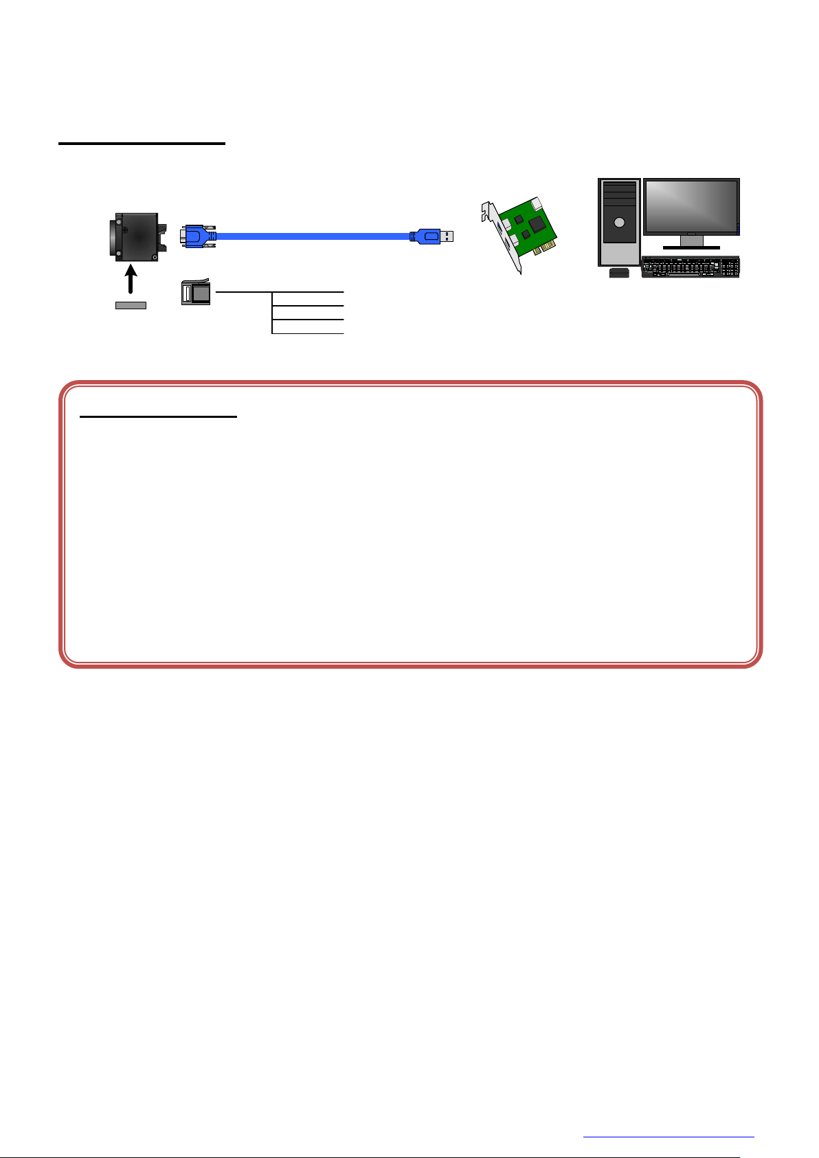
Configuration
The system configuration of this camera series is as follows;
This camera has no accessories, please prepare other equipment separately.
● Camera: This product.
● Camera mounting kit CPTC6M (*1): To fix a camera to a tripod; attach this to the bottom of the camera.
● USB3.0 Cable (*2): This cable is used to connect the camera to host PC. Please use
a USB3.0 cable of Standard A - Micro B. This product is able to
connect a USB cable equipped with screw lock mechanism.
Please use it as needed.
● USB3.0 Interface Card (*2): This is the interface card to connect to the camera. Usually this
card is installed to expansion slot of PC etc.
● e-CON Cable. (*2): This cable is used to input external trigger signal and output GPIO
signal.
We recommend using shielded cable, because there is likely to be
affected by the noise depending on the operating environment of
the camera.
*1: Optional part. Contact your sales representative for details of option units.
*2: Commercial items.
15 / 179
Copyright © 2017 TOSHIBA TELI CORPORATION, All rights reserved. http://www.toshiba-teli.co.jp/en/
Page 17
D4267042B
Camera
Host(PC etc.)
Camera mounting unit
CPTBU
Interface Card
Stream Packet →← Control Packet
USB3.0 Cable
(Mirco B) (Standard A)
1. Line2
2. Line1
3. GND
4. Line0
(e-CON)
e-CON Cable
Notes on Connection:
- Please confirm the power supply of the camera off when plugging in or pulling out the I/O Connector. It causes the
breakdown.
- If your camera is used in a system where its connectors are subjected to strong repetitive shocks, its connectors are
possible to break down. If you use your camera in such a situation, use an USB3.0 cable with a lock screw, and secure
the camera cable as close as possible to the camera body for avoid physical shock to the camera connector.
- About e-CON cable: In the case that electric-wire is long or thin, input and output voltage may not satisfy specifications
of the camera or your system by voltage drop. Please confirm wires’ specifications before use them.
- Los t packets may occur by an electrical characteristic of the transmission line of USB3.0. (USB3.0 Interface Card,
USB3.0 Cable, and USB3.0 HUB).
CPTC6M
Connection
Copyright © 2017 TOSHIBA TELI CORPORATION, All rights reserved. http://www.toshiba-teli.co.jp/en/
16 / 179
Page 18
D4267042B
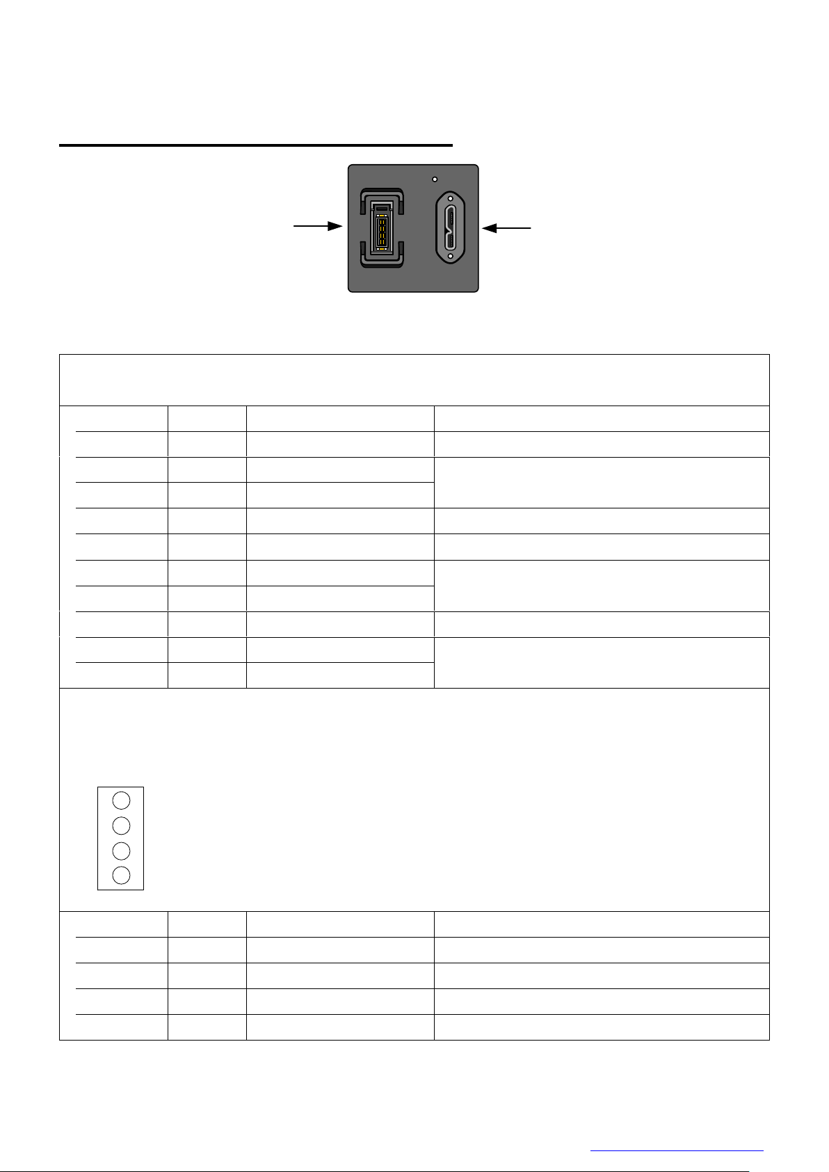
①
②
1. USB3.0 Interface Connector
Connector model: WMUR-10F6L1PH5N (WIN WIN PRECISION INDUSTRIAL)
Pin No.
I/O
Signal
Function
1 -
VBUS
Power
2 I/O
D-
USB2.0 differential pair
3 I/O
D+
4 -
NC
Not connected
5 -
GND
Ground for power return
6 O
SSTX-
SuperSpeed transmitter differential pair
7 O
SSTX+
8 -
GND_DRAIN
Ground for SuperSpeed signal return
9 I
SSRX-
SuperSpeed receiver differential pair
10 I SSRX+
2. I/O Connector
Connector (Camera side) 37204-62B3-004PL (Sumitomo 3M) or equivalent
Matching connector (Cable side) Connectors which conformed to e-CON
e.g. 37104 series (Sumitomo 3M), RITS 4P series (Tyco)
* Matching connector is not an accessory of this product.
Pin assignment
↑TOP
*Above figure is connector view from insert side.
Pin No.
I/O
Signal
Function
1 I/O
Line2
GPIO Input / Output
2 O
Line1
GPIO Output
3 -
GND
Ground
4 I
Line0
GPIO Input
1
2
3
4
Connector Pin Assignment
Rear View
Copyright © 2017 TOSHIBA TELI CORPORATION, All rights reserved. http://www.toshiba-teli.co.jp/en/
17 / 179
Page 19

D4267042B
Outline Drawing
18 / 179
Copyright © 2017 TOSHIBA TELI CORPORATION, All rights reserved. http://www.toshiba-teli.co.jp/en/
Page 20

D4267042B
Model Name
DU1207MG
Optical part
Optical glass
Imager
CMOS image sensor
Number of Video out pixels (H) × (V)
4096 x 3000
Optical Size
type1.1
Scanning area (H) × (V)[mm]
14.19 x 10.34
Pixel size (H) × (V)[μm]
3.45 ×3.45
Scan method
Progressive
Electronic shutter method
Global shutter
Aspect ratio
4 : 3
Sensitivity
860lx, F5.6, 1/32s
Minimum illuminance
2lx (F1.4, Gain +24dB, Video Level 50%)
Power supply
DC +5V5% (from USB connector)
Power consumption (*1)
4.0W (maximum)
Interface
USB 3.0 (Only SuperSpeed is supported)
Transmission speed
5Gbps (maximum)
Protocol
USB3 Vision
Image format
Mono8, Mono10, Mono12
Maximum Frame rate (*2)
Mono8
32 fps
Mono10, Mono12
16 fps
Dimensions
40 mm(W) x 40 mm (H) x 35 mm (D) (Not including protrusion)
Mass
90g
Lens mount
C-mount
Flange back
17.526mm
Camera body grounding: insulation status
Conductive between circuit GND and camera body
General Specifications
● B/W model
*1, *2 at the all pixel readout
Copyright © 2017 TOSHIBA TELI CORPORATION, All rights reserved. http://www.toshiba-teli.co.jp/en/
19 / 179
Page 21

D4267042B
Model Name
DU1207MCG
DU1207MCF
Optical Part
Optical glass
IR cut filter
Imager
CMOS image sensor
Number of Video out pixels (H) × (V)
4096 x 3000
Optical Size
Type 1.1
Scanning area (H) × (V)[mm]
14.19 x 10.34
Pixel size (H) × (V)[μm]
3.45 ×3.45
Scan method
Progressive
Electronic shutter method
Global shutter
Aspect ratio
4 : 3
Sensitivity
1150lx, F5.6, 1/31s
1425lx, F5.6, 1/31s
Minimum illuminance
3lx (F1.4, Gain +24dB, Video Level 50%)
Power supply
DC +5V5% (from USB connector)
Power consumption (*1)
4.5W (maximum)
Interface
USB 3.0 (Only SuperSpeed is supported)
Transmission speed
5Gbps (maximum)
Protocol
USB3 Vision
Image format
RGB, BGR, YUV422, YUV411, Bayer8, Bayer10, Bayer12, Mono8
Maximum Frame rate (*2)
Bayer8, Mono8
31 fps
YUV411
21 fps
YUV422
16 fps
Bayer10, Bayer12
16 fps
RGB, BGR
10 fps
Dimensions
40 mm(W) x 40 mm (H) x 35 mm (D) (Not including protrusion)
Mass
90g
Lens mount
C-mount
Flange back
17.526mm
Camera body grounding: insulation status
Conductive between circuit GND and camera body
● Color model
*1, *2 at the all pixel readout
Copyright © 2017 TOSHIBA TELI CORPORATION, All rights reserved. http://www.toshiba-teli.co.jp/en/
20 / 179
Page 22
D4267042B
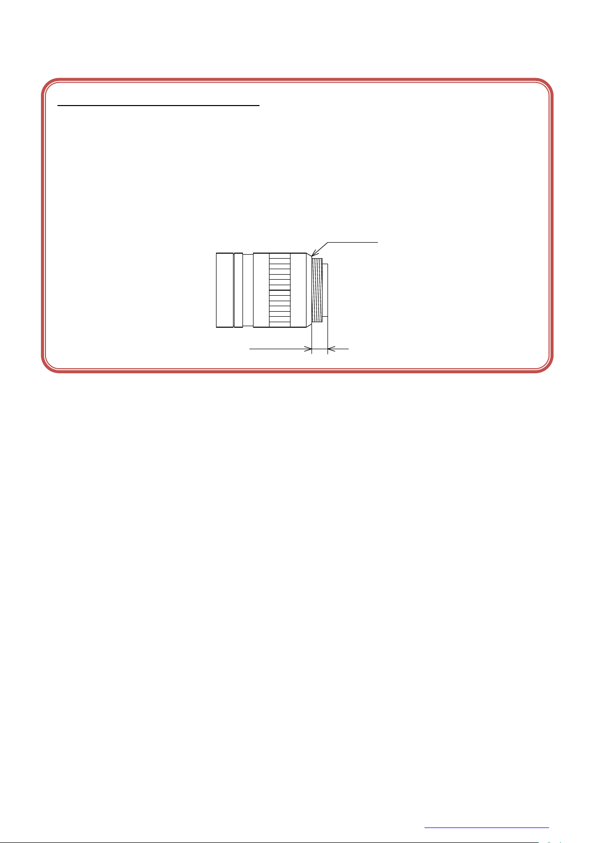
Notes on combination of C-mount lens:
- Depending on the lens you use, the performance of the camera may not be brought out fully due to the deterioration in
resolution and brightness in the peripheral area, occurrence of a ghost, aberration and others. When you check the
combination between the lens and camera, be sure to use the lens you actually use.
- In addition, use a mounting screw free from defects and dirt. Otherwise, the camera may be unable to be removed.
- As for the C-mount lens used combining this camera, the projection distance from bottom of the screw should use
8mm or less.
10mm or less
C-mount lens
Bottom of
the screw
8mm or less
21 / 179
Copyright © 2017 TOSHIBA TELI CORPORATION, All rights reserved. http://www.toshiba-teli.co.jp/en/
Page 23

D4267042B
Camera state
Lamp indication
No power
Off
Link detection in progress
Fast flash green (ON:20ms, OFF:60ms)
Connection Error
Flash alternate red / green
SuperSpeed connected, but no data being transferred
Flash green (ON: 200ms, OFF: 800ms)
SuperSpeed connected, waiting for trigger
Flash orange (ON: 200ms, OFF: 800ms)
Data being transferred
Fast flash green (ON:60ms, OFF:20ms)
Error during data transfer
Solid Red (Time period: 500ms)
Stand-by
Super slow flash orange (ON:200ms, OFF: 2800ms)
LED Status
Copyright © 2017 TOSHIBA TELI CORPORATION, All rights reserved. http://www.toshiba-teli.co.jp/en/
22 / 179
Page 24
D4267042B
Inside
DC3.3V
0V
10kΩ
Notes of external trigger signal:
Depending on cable length, cable kinds and input current of trigger input line, Random Trigger Shutter operation may not
satisfy timing specification or camera may not receive EXT_TRIG signal. Please confirm it before use.
Notes of input level:
Line0 and Line2 have different input level. Please use input level within the voltage described in this specification.
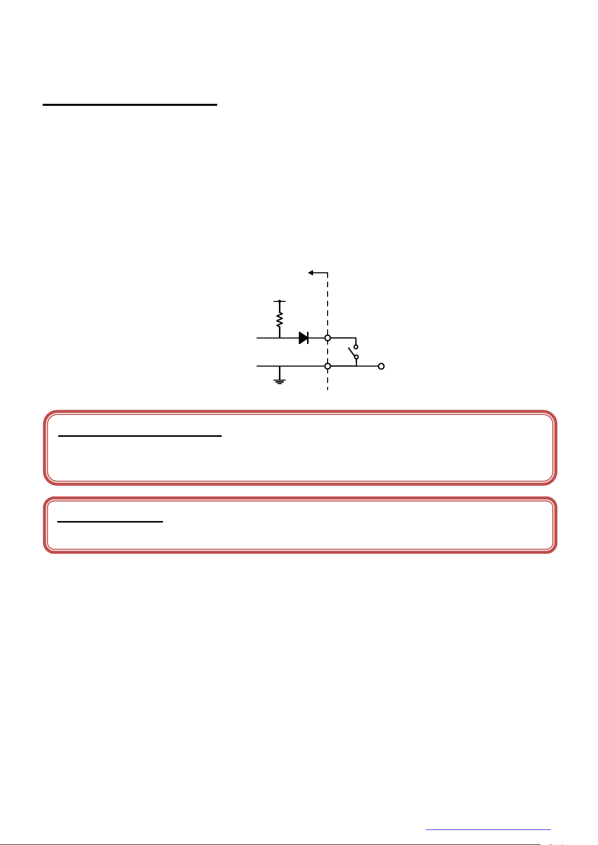
I/O Specification
● Signal Specification
- Line0 (GPIO Input, I/O connector : 4 pin)
Input Circuit : LVTTL
Level : Low 0 ~ 0.5V, High 2.0 ~ 24.0V
Polarity : High active / Low active (initial factory setting: Low active)
Pulse Width : Minimum 50μs
Input circuit diagram
Copyright © 2017 TOSHIBA TELI CORPORATION, All rights reserved. http://www.toshiba-teli.co.jp/en/
23 / 179
Page 25
D4267042B
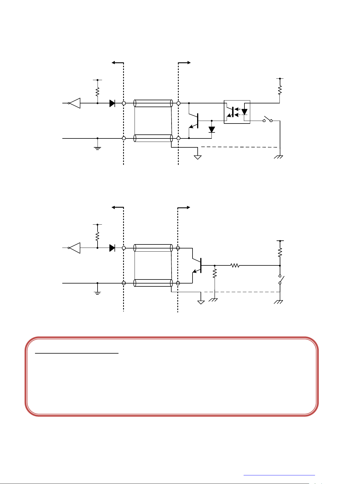
● External trigger input recommended circuit
CAMERA Inside
DC3.3V
10kΩ
4
3
Photocoupler
Camera
GND
Your
GND
Your system
Your
Secondary GND
Your
GND
Your system
Your
FRAME GND
DC3.3V
10kΩ
4
3
Camera
GND
CAMERA Inside
Notes of trigger input cable:
- The recognition of the trigger signal depends on the length, characteristic or driving current of the cable. Therefore
please confirm your system about those conditions.
- Pin 3 is conducted with camera frame.
Using shield cable, terminal processing of the shield is referred as above.
- Please confirm the EMC adaptability in whole of your system.
- Isolated I/F
- Non-Isolated I/F
Copyright © 2017 TOSHIBA TELI CORPORATION, All rights reserved. http://www.toshiba-teli.co.jp/en/
24 / 179
Page 26
D4267042B
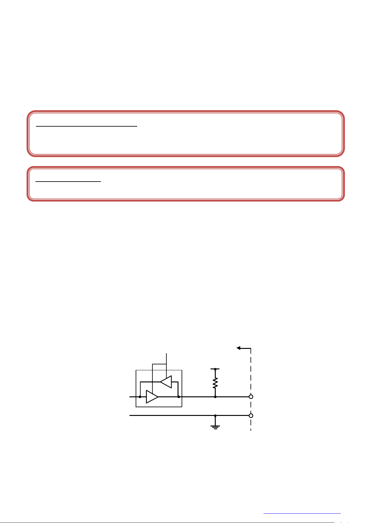
- Line2 (GPIO Input / Output, initial factory setting: Input, I/O connector : 1 pin)
Inside
DC5.0V
10kΩ
1
3
IOLineModeAll
Notes of external trigger signal:
Depending on cable length, cable kinds and input current of trigger input line, Random Trigger Shutter operation may not
satisfy timing specification or camera may not receive EXT_TRIG signal. Please confirm it before use.
Notes of input level:
Line0 and Line2 have different input level. Please use input level within the voltage described in this specification.
- Input signal specification
Level : Low 0 ~ 0.5V, High 4.0 ~ 5.0V
Polarity : High active / Low active (initial factory setting: Low active)
Pulse Width : Minimum 50μs
- Output signal specification
Output Circuit : 5V CMOS
Maximum Current : +/-32mA
Polarity : High active / Low active (initial factory setting: Low active)
Signal Source : TIMER0 ACTIVE
USER OUTPUT
EXPOSURE ACTIVE
FRAME ACTIVE
FRAME TRANSFER
FRAME TRIGGER WAIT
Input / Output circuit diagram
Copyright © 2017 TOSHIBA TELI CORPORATION, All rights reserved. http://www.toshiba-teli.co.jp/en/
25 / 179
Page 27

D4267042B
- Line1 (GPIO Output, I/O connector : 2 pin)
Output Circuit : 5V CMOS
Maximum Current : +/-32mA
Polarity : High active / Low active (initial factory setting: Low active)
Signal Source : TIMER0 ACTIVE
USER OUTPUT
EXPOSURE ACTIVE
FRAME ACTIVE
FRAME TRANSFER
FRAME TRIGGER WAIT
26 / 179
Copyright © 2017 TOSHIBA TELI CORPORATION, All rights reserved. http://www.toshiba-teli.co.jp/en/
Page 28
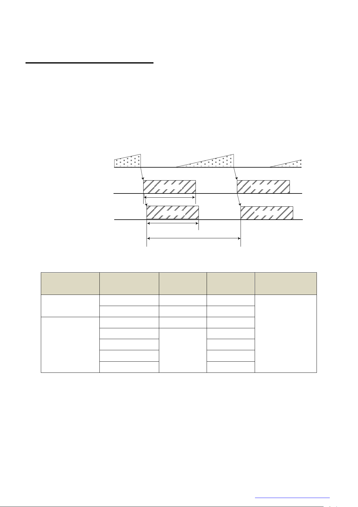
D4267042B
T1
Sensor Output
Exposure
Image Image
T3
T2
Image Image
USB Streaming
Model Name
format
T1
[ms]
T2
[ms]
T3
[s]
DU1207MG
Mono8
15.8
30.85
1/(Frame Rate setting)
Mono10, Mono12
22.0
61.83
DU1207MCG/CF
Bayer8, Mono8
15.8
30.85
YUV 4:1:1
22.0
46.28
YUV 4:2:2
61.83
Bayer10, Bayer12
61.83
RGB, BGR
92.57
Timing Specification
Image data outputs are transferred with USB bulk transfer. Timing numerical value below is described by
absolute prerequisite that camera can use transmission band without restriction of other device. When there
is other device on the same bus, the value described below is not guaranteed.
● In Manual Shutter mode
Copyright © 2017 TOSHIBA TELI CORPORATION, All rights reserved. http://www.toshiba-teli.co.jp/en/
27 / 179
Page 29

D4267042B
Image
USB Streaming
Exposure
TRIG_IN
T4
T2
Image
USB Streaming
Exposure
TRIG_IN
T4
T2
T5
Model Name
format
T4
[μs]
T5
[μs]
DU1207MG
Mono8
16.1
30.4
Mono10, Mono12
22.3
36.6
DU1207MCG/CF
Bayer8, Mono8
16.1
30.4
YUV 4:1:1
22.3
36.6
YUV 4:2:2
Bayer10, Bayer12
RGB, BGR
Notes of random trigger shutter mode:
- In the period when FRAME_TRIGGER_WAIT (GPIO signal) is inactive, user must not input external trigger signal to
this camera.
- When the interval of the input trigger signal is extremely short, or when the trigger signal is noisy, there is a possibility
of causing the malfunction. In this case, please input a proper trigger signal.
● In Random Trigger Shutter mode
Edge mode / Bulk mode (at all pixels readout)
Level mode (at all pixels readout)
* The value of T2 is the same as the value of normal shutter mode.
* T4 and T5 are typical value.
* In case that the Trigger mode is Level mode, exposure time is 14.26μs longer than trigger signal width due
to the CMOS sensor specifications.
Copyright © 2017 TOSHIBA TELI CORPORATION, All rights reserved. http://www.toshiba-teli.co.jp/en/
28 / 179
Page 30
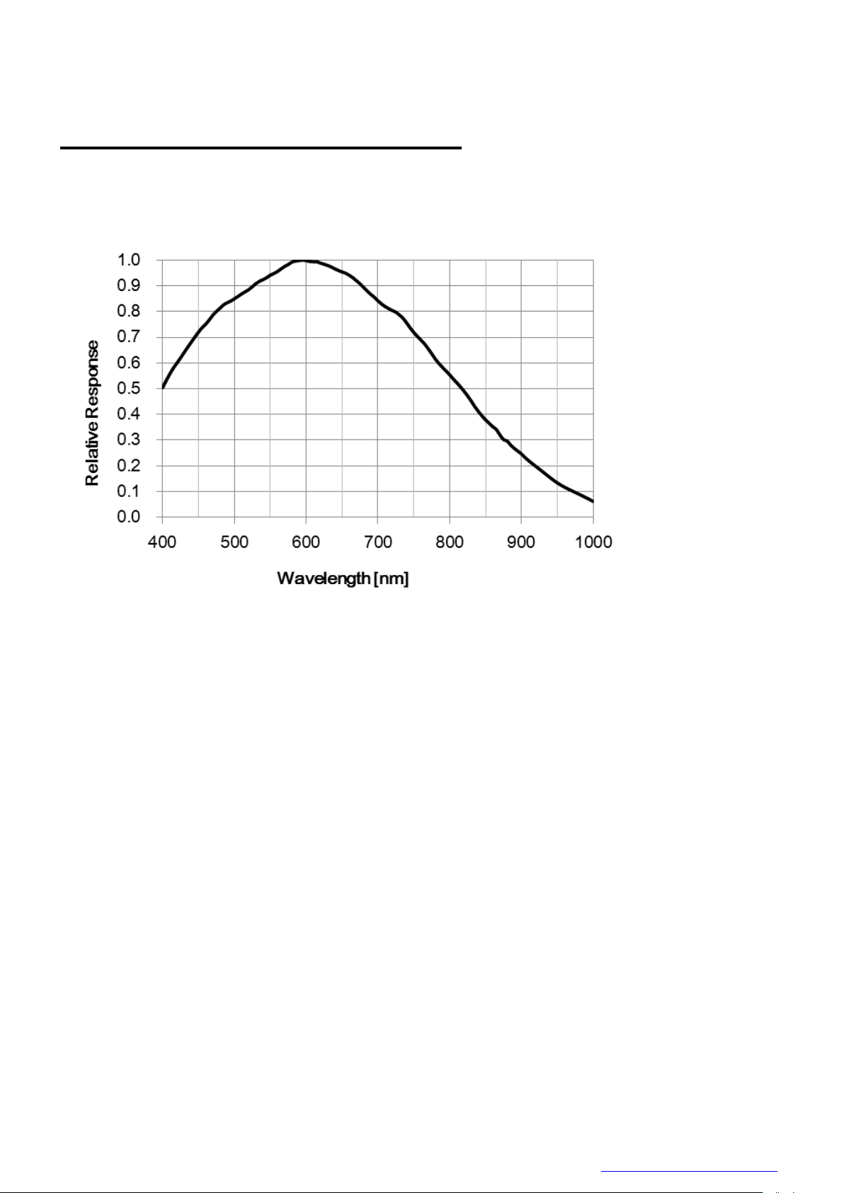
D4267042B
Typical Spectral Response
* The lens characteristics and light source characteristics is not reflected in table.
● DU1207MG
29 / 179
Copyright © 2017 TOSHIBA TELI CORPORATION, All rights reserved. http://www.toshiba-teli.co.jp/en/
Page 31

D4267042B
●DU1207MCG
R
G
B
R
G
B
●DU1207MCF
Copyright © 2017 TOSHIBA TELI CORPORATION, All rights reserved. http://www.toshiba-teli.co.jp/en/
30 / 179
Page 32

D4267042B
Notes on Heat Radiation:
The temperature of camera housing must be kept less than 65 °C.
Please provide sufficient heat radiation depending on your installation.
Operating Ambient Conditions
● Ambient conditions
- Performance Assurance
Temperature: 0°C ~ 40°C, Camera housing temperature: less than 55 °C
Humidity: 10% ~ 90% (no condensation)
- Operating Assurance
Temperature: -5°C to +45°C, Camera housing temperature: less than 65 °C
Humidity: 10% to 90% (no condensation)
- Storage Assurance
Temperature: -20°C to +60°C
Humidity: 90% or less (no condensation)
Copyright © 2017 TOSHIBA TELI CORPORATION, All rights reserved. http://www.toshiba-teli.co.jp/en/
31 / 179
Page 33

D4267042B
Notes on Conformity of the EMC:
The adaptability of the safety standard of this camera is assured in the condition of combination with the following parts:
- USB Cable USB3-KR1-A-MBS-030 (OKI Electric Cable Co., Ltd.)
- e-CON Cable 3.0m, Shield cable (Fabricated parts)
Parts:
- e-CON connector XN2A-1470 (OMRON Corporation)
- Shielded wire UL1533 (AWG28) (Hitachi cable, Ltd.)
Connection:
e-CON
1
2
3
4
BNC
GPIO(Line2)
GPIO(Line1)
GND
TRIG IN(Line0)
GPIO(Line2)
GPIO(Line1)
TRIG IN(Line0)
BNC
Please confirm the EMC adaptability when it combines with parts other than them.
● EMC Conditions
- EMI (Electro-Magnetic Interference): EN61000-6-3
FCC Part 15 Subpart B Class A
- EMS (Electro-Magnetic Susceptibility): EN61000-6-2
32 / 179
Copyright © 2017 TOSHIBA TELI CORPORATION, All rights reserved. http://www.toshiba-teli.co.jp/en/
Page 34

D4267042B
Category
Function
USB3 Vision
Bootstrap Registers
USB3 Vision standard registers
DeviceControl
DeviceControl
Device information
ImageFormatControl
ImageFormatSelector
Image format selection
Scalable
Scalable control
Binning
Binning control
Decimation
Decimation control
Reverse
Image flip
PixelFormat
Pixel format selection
BayerProcessingMode
BayerProcessingMode control
TestPattern
Test pattern control
AcquisitionControl
AcquisitionControl
Image stream start / stop
ImageBuffer
Image buffer control
TriggerControl
Trigger control
ExposureControl
Exposure time control
DigitalIOControl
DigitalIOControl
GPIO signal control
CounterAndTimerControl
TimerControl
Timer0Active signal control
AnalogControl
Gain
Gain control
BlackLevel
Black level control
Gamma
Gamma correction
Hue
Hue control
Saturation
Saturation control
BalanceRatio
Color gain (R, B)
BalanceWhiteAuto
Execute auto white balance once
ColorCorrectionMatrix
Color matrix correction
ALCControl
ALCControl
ALC control
LUTControl
LUTControl
LUT control
UserSetControl
UserSetControl
Load / Save user setting
EventControl
EventControl
Event packet control
VenderUniqueControl
FrameSynchronization
Frame synchronization control
LEDIndicatorLuminance
LED luminance control
AntiGlitch
AntiGlitch control
AntiChattering
AntiChattering control
DPCControl
DPCControl
Defect pixel correction control
SequentialShutterControl
SequentialShutterControl
Sequential shutter control
ChunkDataControl
Chunk
ChunkDataControl
Functions
This section introduces standard functions. DU1207M series provides following functions.
Copyright © 2017 TOSHIBA TELI CORPORATION, All rights reserved. http://www.toshiba-teli.co.jp/en/
33 / 179
Page 35

D4267042B
Features supported by each model are as follows.
Function
DU1207MG
DU1207MCG
DU1207MCF
Bootstrap Registers
○ ○ ○
DeviceControl
○ ○ ○
ImageFormatSelector
○ ○ ○
Scalable
○ ○ ○
Binning
○ ○ ○
Decimation
○ ○ ○
Reverse
○ ○ ○
PixelFormat
○ ○ ○
TestPattern
○ ○ ○
BayerProcessingMode
- ○ ○
AcquisitionControl
○ ○ ○
ImageBuffer
○ ○ ○
TriggerControl
○ ○ ○
ExposureControl
○ ○ ○
DigitalIOControl
○ ○ ○
TimerControl
○ ○ ○
Gain
○ ○ ○
BlackLevel
○ ○ ○
Gamma
○ ○ ○
Hue
- ○ ○
Saturation
- ○ ○
BalanceRatio
- ○ ○
BalanceWhiteAuto
- ○ ○
ColorCorrectionMatrix
- ○ ○
ALCControl
○ ○ ○
LUTControl
○ ○ ○
UserSetControl
○ ○ ○
EventControl
○ ○ ○
FrameSynchronization
○ ○ ○
LEDIndicatorLuminance
○ ○ ○
AntiGlitch
○ ○ ○
AntiChattering
○ ○ ○
DPCControl
○ ○ ○
SequentialShutterControl
○ ○ ○
Chunk
○ ○ ○
Details of each feature are described in following pages.
Copyright © 2017 TOSHIBA TELI CORPORATION, All rights reserved. http://www.toshiba-teli.co.jp/en/
34 / 179
Page 36

D4267042B
USB3 Vision ABRM
Register
Address
GenICam
Interface
Length
Byte / [bit]
Access
Description
ManufactureName
0x00004
String
64
R
Manufacturer name
ModelName
0x00044
String
64
R
Device model name
FamilyName
0x00084
String
64
R
Device family name
DeviceVersion
0x000C4
String
64
R
Device version
ManufacturerInfo
0x00104
String
64
R
Additional manufacturer specific information
SerialNumber
0x00144
String
64
R
Serial number of the device
UserDefinedName
0x00184
String
64
R/W
User defined name of the device.
SBRM Address
0x001D8
Integer 8 R
Start Address of the SBRM
Bootstrap Registers
This camera is based on USB3 Vision.
Please refer to USB3 Vision specification for details about Bootstrap Registers defined in USB3 Vision.
AIA (Automated Imaging Association) USB3 Vision Homepage.
http://www.visiononline.org/vision-standards-details.cfm?type=11
Followings are commonly used registers.
- UserDefinedName
UserDefinedName is used for assigning unique ID to the camera.
You can store an arbitrary string into non-volatile memory.
- StreamEnable
When StreamEnable bit is set. Camera starts to send image streaming.
TeliU3vSDK / TeliCamSDK require some setups on your application in opening and closing the stream
channel. Please refer to the library manual for details.
- EventEnable
When EventEnable bit is set. Camera is enabled to send event packets.
TeliU3vSDK / TeliCamSDK require some setups on your application in opening and closing the event
channel. Please refer to the library manual for details.
● Registers
Copyright © 2017 TOSHIBA TELI CORPORATION, All rights reserved. http://www.toshiba-teli.co.jp/en/
35 / 179
Page 37

D4267042B
USB3 Vision SBRM
Register
Address
GenICam
Interface
Length
Byte / [bit]
Access
Description
SIRMAddress
0x10020
Integer 8 R
Start Address of the SIRM
EIRMAddress
0x1002C
Integer 8 R
Start Address of the EIRM
IIDC2Address
0x10038
Integer 8 R
Start Address of the IIDC2
CurrentSpeed
0x10040
Integer
[3..0]
R
[0]: Low-Speed connection (not supported)
[1]: Full-Speed connection (not supported)
[2]: High-Speed connection
[3]: Super-Speed connection
USB3 Vision SIRM
Register
Address
GenICam
Interface
Length
Byte / [bit]
Access
Description
StreamEnable
0x20004
Integer
[0]
R/W
0: Disable data transfer of the streaming
1: Enable data transfer of the streaming
SIRequiredPayloadSize
0x20008
Integer 8 R
Minimum required payload size with current settings
SIRequiredLeaderSize
0x20010
Integer 4 R
Minimum required leader size
SIRequiredTrailerSize
0x20014
Integer 4 R
Minimum required trailer size
SIMaximumLeaderSize
0x20018
Integer 4 R
Maximum leader size
SIPayloadTransferSize
0x2001C
Integer 4 R
Expected Size of a single Payload Transfer
SIPayloadTransferCount
0x20020
Integer 4 R
Expected Number of Payload Transfers
SIPayloadFinalTransfer1Size
0x20024
Integer 4 R
Size of first final Payload transfer
SIPayloadFinalTransfer2Size
0x20028
Integer 4 R
Size of second final Payload transfer
SIMaximumTrailerSize
0x2002C
Integer 4 R
Maximum trailer size
USB3 Vision EIRM
Register
Address
GenICam
Interface
Length
Byte / [bit]
Access
Description
EventEnable
0x30000
Integer
[0]
R/W
0: Disable data transfer of the event
1: Enable data transfer of the event
● Note
DU series doesn’t support image transfer in High-Speed connection.
CurrentSpeed register could be used for showing the warning message on your application when
camera is connected to USB2.0 port.
Copyright © 2017 TOSHIBA TELI CORPORATION, All rights reserved. http://www.toshiba-teli.co.jp/en/
36 / 179
Page 38

D4267042B
Register
Address
GenICam
Interface
Length
Byte / [bit]
Access
Description
DeviceReset
0x20003C
Command
[0]
W
[1] Resets the device.
DeviceVendorName
0x200070
String
16
R
Same as ManufactureName in Bootstrap Registers
DeviceModelName
0x200090
String
16
R
Same as ModelName in Bootstrap Registers
DeviceManufactureInfo
0x2000B0
String
16
R
Same as ManufacturerInfo in Bootstrap Registers
DeviceVersion
0x2000D0
String
16
R
Same as DeviceVersion in Bootstrap Registers
DeviceID
0x200110
String
16
R
Same as SerialNumber in Bootstrap Registers
DeviceControl
Registers of this category provide various information of the camera.
● Registers
● Note
- DeviceReset
Camera executes the USB Bus reset operation by DeviceReset command.
- Plug-and-play happens, camera handles used in the application become invalid.
- The application is required to close and re-open the camera.
Copyright © 2017 TOSHIBA TELI CORPORATION, All rights reserved. http://www.toshiba-teli.co.jp/en/
37 / 179
Page 39

D4267042B
Format2
Format1
Format0
ImageSize
Width
Height
OffsetX
OffsetY
BinningHorizontal
BinningVertical
DecimationHorizontal
DecimationVertical
ReverseX
ReverseY
PixelFormat
PixelEndian
ImageSize
Width
Height
OffsetX
OffsetY
BinningHorizontal
BinningVertical
DecimationHorizontal
DecimationVertical
ReverseX
ReverseY
PixelFormat
PixelEndian
ImageSize
Width
Height
OffsetX
OffsetY
BinningHorizontal
BinningVertical
DecimationHorizontal
DecimationVertical
ReverseX
ReverseY
PixelFormat
PixelEndian
ImageFormatControl
Registers of this category are related to image format control.
Camera has three different banks of image format. You can select image format by ImageFormatSelector.
Copyright © 2017 TOSHIBA TELI CORPORATION, All rights reserved. http://www.toshiba-teli.co.jp/en/
38 / 179
Page 40

D4267042B
● GenICam Node
Name
Interface
Length
Byte / [bit]
Access
Description
ImageFormatSelector
IEnumeration
4
R/W
Selects an image format.
Register
Field
Address
Length
Byte / [bit]
Access
Description
ImageFormatSelector
Implemented
0x202020
[31]
R
Returns the state whether the function is implemented.
ListOfElements
0x20202C
16
R
[0] : Format0
[1] : Format1
[2] : Format2
Value
0x20203C
4
R/W
Selects an image format.
ImageFormat 0 - 2
Width
Height
OffsetX
OffsetY
BinningHorizontal
BinningVertical
DecimationHorizontal
DecimationVertical
ReverseX
ReverseY
PixelFormat
PixelEndian
● IIDC2 Register
List of registers to be applied by ImageFormatSelector
Copyright © 2017 TOSHIBA TELI CORPORATION, All rights reserved. http://www.toshiba-teli.co.jp/en/
39 / 179
Page 41

D4267042B
API name
Description
GetCamImageFormatSelector
Get current ImageFormatSelector value
SetCamImageFormatSelector
Set new ImageFormatSelector value
Integer
String
0(*)
Format0
1
Format1
2
Format2
// GenICam node handle
CAM_NODE_HANDLE hSelector = NULL;
// Retrieve GenICam node.
Nd_GetNode(s_hCam, "ImageFormatSelector", &hSelector);
// ImageFormat = Format2
Nd_SetEnumStrValue(s_hCam, hSelector, "Format2");
● Control with TeliCamSDK
Camera feature API
Control ImageFormat using dedicated API.
Please refer to [Controlling camera feature functions] in [TeliCamAPI Library manual] for more detail.
GenICam function API
Control ImageFormat using GenICam API.
ImageFormat
Select an image format by ‘ImageFormatSelector’.
Integer value and string value of Enumeration are as follows.
* initial factory setting
Please refer to [INode functions], [IEnumeration node functions] in [TeliCamAPI Library manual] for
more detail.
Copyright © 2017 TOSHIBA TELI CORPORATION, All rights reserved. http://www.toshiba-teli.co.jp/en/
40 / 179
Page 42

D4267042B
API name
Description
Cam_ReadReg
Read register value
Cam_WriteReg
Write register value
// ImageFormat = Format2
uint32_t uiSelector;
uiSelector = 2;
Cam_WriteReg(s_hCam, 0x20203C, 1, &uiSelector);
Register access API
Control Gain by accessing IIDC2 registers directly.
ImageFormat
Write to ‘Value’ field of ‘ImageFormatSelector’ register.
Please refer to [Camera functions] in [TeliCamAPI Library manual] for more detail.
● Note
Changing ‘ImageFormatSelector’ register value is invalid during image stream data output.
Copyright © 2017 TOSHIBA TELI CORPORATION, All rights reserved. http://www.toshiba-teli.co.jp/en/
41 / 179
Page 43

D4267042B
⇒
( X , Y )=( 4 * i , 2 * j )
A + 4 * m
B + 2 * n
Scalable
Scalable function reads out the region of interest (ROI) of the sensor.
If height size is set small, it is possible to increase the frame rate.
Only single rectangle is selectable. Concave or convex shape is not selectable.
- Window size: {A + 4 × m (H)} × {B + 2 × n (V)}
A, B = minimum unit size
m, n = integer
The window size is equal or less than maximum image size.
- Start address: {4 x i (H)} x {2 x j (V)}
i, j = integer
The window size is equal or less than maximum image size.
Scalable
42 / 179
Copyright © 2017 TOSHIBA TELI CORPORATION, All rights reserved. http://www.toshiba-teli.co.jp/en/
Page 44

D4267042B
Name
Interface
Length
Byte / [bit]
Access
Description
Width
IInteger
4
R/W
Sets width (in pixels) of the image data.
Height
IInteger
4
R/W
Sets Height (in pixels) of the image data.
OffsetX
IInteger
4
R/W
Sets horizontal offset (in pixels) from the origin to the region of interest.
OffsetY
IInteger
4
R/W
Sets vertical offset (in pixels) from the origin to the region of interest.
Register
Field
Address
Length
Byte / [bit]
Access
Description
ImageSize
Implemented
0x202060
[31]
R
Returns the state whether the function is implemented.
OffsetXMin
0x20206C
4
R
Returns the minimum starting position of the horizontal direction
OffsetXInc
0x202070
4
R
Returns the unit starting position of the horizontal direction
WidthMin
0x202074
4
R
Returns the minimum size of width
WidthInc
0x202078
4
R
Returns the unit size of width
SensorWidth
0x20207C
4
R
Returns effective width of the sensor in pixels
OffsetYMin
0x202080
4
R
Returns the minimum starting position of the vertical direction
OffsetYInc
0x202084
4
R
Returns the unit starting position of the vertical direction
HeightMin
0x202088
4
R
Returns the minimum size of height
HeightInc
0x20208C
4
R
Returns the unit size of height.
SensorHeight
0x202090
4
R
Returns effective Height of the sensor in pixels
OffsetX
0x202094
4
RW
Sets horizontal offset (in pixels) from the origin to the region of interest
Width
0x202098
4
RW
Sets width (in pixels) of the image data.
OffsetY
0x20209C
4
RW
Sets vertical offset (in pixels) from the origin to the region of interest
Height
0x2020A0
4
RW
Sets Height (in pixels) of the image data.
● GenICam Node
● IIDC2 Register
Copyright © 2017 TOSHIBA TELI CORPORATION, All rights reserved. http://www.toshiba-teli.co.jp/en/
43 / 179
Page 45

D4267042B
API name
Description
GetCamSensorWidth
Get effective width of the sensor in pixels
GetCamSensorHeight
Get effective height of the sensor in pixels
GetCamRoi
Get ROI (Region of Interest) of the camera
SetCamRoi
Set ROI (Region of Interest) to the camera
GetCamWidthMinMax
Get minimum and maximum value
GetCamWidth
Get width of image
SetCamWidth
Set width of image
GetCamHeightMinMax
Get minimum and maximum value
GetCamHeight
Get height of image
SetCamHeight
Set height of image
GetCamOffsetXMinMax
Get minimum and maximum value
GetCamOffsetX
Get horizontal offset of image
SetCamOffsetX
Set horizontal offset of image
GetCamOffsetYMinMax
Get minimum and maximum value
GetCamOffsetY
Get vertical offset of image
SetCamOffsetY
Set vertical offset of image
● Control with TeliCamSDK
Camera feature API
Control Scalable using dedicated API.
Please refer to [Controlling camera feature functions] in [TeliCamAPI Library manual] for more detail.
Copyright © 2017 TOSHIBA TELI CORPORATION, All rights reserved. http://www.toshiba-teli.co.jp/en/
44 / 179
Page 46

D4267042B
// GenICam node handle
CAM_NODE_HANDLE hWidth = NULL;
CAM_NODE_HANDLE hHeight = NULL;
CAM_NODE_HANDLE hOffsetX = NULL;
CAM_NODE_HANDLE hOffsetY = NULL;
// ROI = {OffsetX, Width, OffsetY, Height};
uint64_t ROI[] = {612,1224, 512,1024};
// Retrieve GenICam node.
Nd_GetNode(s_hCam, “Width”, &hWidth);
Nd_GetNode(s_hCam, “Height”, &hHeight);
Nd_GetNode(s_hCam, “OffsetX”, &hOffsetX);
Nd_GetNode(s_hCam, “OffsetY”, &hOffsetY);
// Set ROI
Nd_SetIntValue(s_hCam, hWidth, ROI[1]);
Nd_SetIntValue(s_hCam, hOffsetX, ROI[0]);
Nd_SetIntValue(s_hCam, hHeight, ROI[3]);
Nd_SetIntValue(s_hCam, hOffsetY, ROI[2]);
API name
Description
Cam_ReadReg
Read register value
Cam_WriteReg
Write register value
// ROI = {OffsetX, Width, OffsetY, Height};
uint32_t ROI[] = {612,1224, 512,1024};
// Set ROI (in one by one)
Cam_WriteReg(s_hCam, 0x202094, 1, &ROI[0]);
Cam_WriteReg(s_hCam, 0x202098, 1, &ROI[1]);
Cam_WriteReg(s_hCam, 0x20209C, 1, &ROI[2]);
Cam_WriteReg(s_hCam, 0x2020A0, 1, &ROI[3]);
// Set ROI (in block)
Cam_WriteReg(s_hCam, 0x202094, 4, &ROI[0]);
GenICam function API
Control Scalable using GenICam API.
Scalable
If you’re going to reduce width size, set Width, first. Then set OffsetX.
If you’re going to increase width size, set OffsetX, first. Then set Width.
If you’re going to reduce height size, set Height, first. Then set OffsetY.
If you’re going to increase height size, set OffsetY, first. Then set Height.
Please refer to [INode functions] and [IInteger node functions] in [TeliCamAPI Library manual] for more
detail.
Register access API
Control Scalable by accessing IIDC2 registers directly.
Copyright © 2017 TOSHIBA TELI CORPORATION, All rights reserved. http://www.toshiba-teli.co.jp/en/
Scalable
Write to ‘Value’ field of ‘OffsetX’, ’Width’, ‘OffsetY’, ‘Height’ register.
45 / 179
Page 47

D4267042B
In IIDC2 registers access,
Model
DU1207MG/MCG/MCF
Width/OffsetX unit size
4
Height/OffsetY unit size
2
Minimum unit size
64 x 64
Maximum unit size(*)
4096 x 3000
you can set OffsetX, Width, OffsetY, Height in any order. (in one by one access)
you can also set OffsetX, Width, OffsetY, Height with single access. (in block access)
Please refer to [Camera functions] in [TeliCamAPI Library manual] for more detail.
Minimum/Maximum Value
● Note
* initial factory setting
Changing “Width”, “Height”, “OffsetX”, “OffsetY” register value is invalid during image stream data output.
46 / 179
Copyright © 2017 TOSHIBA TELI CORPORATION, All rights reserved. http://www.toshiba-teli.co.jp/en/
Page 48

D4267042B
2048
2448
1224
All pixel readout
Binning
1024
4096
3000
2048
1500
Binning operation (e.g. Binning 2x2)
Binning
In the binning mode, a pixel is added with the neighboring pixel(s).
This increases the sensitivity of the image. It’s alike scalable, the frame rate can be faster and USB bandwidth
occupation decrease.
Copyright © 2017 TOSHIBA TELI CORPORATION, All rights reserved. http://www.toshiba-teli.co.jp/en/
47 / 179
Page 49

D4267042B
● Framerate in each output format (fps)
Mono8
H
Mono10
/Mono12
H
1 2 4 1 2 4 V 1
32
62
62
V 1
16
32
42 2 64
121
121 2
32
64
83 4 121
121
121 4
64
83
83
Bayer8
/Mono
H
Bayer10
/Bayer12
H
1 2 4 1 2 4 V 1
31
31
31
V 1
16
28
28 2 31
31
31 2
28
28
28 4 31
31
31 4
28
28
28
YUV411
H
YUV422
H
1 2 4 1 2 4 V 1
21
28
28
V 1
16
28
28 2 28
28
28 2
28
28
28 4 28
28
28 4
28
28
28
RGB
/BGR
H
1 2 4 V 1
10
21
28 2 21
28
28 4 28
28
28
Binning
DU1207MG
DU1207MCG
/ DU1207MCF
Vertical
Horizontal
Analog stage
Digital stage
Analog stage
Digital stage
1 2 - ✓ - ✓ 1 4 - ✓ - ✓ 2 1 ✓ - - ✓ 2 2 ✓ - - ✓ 2 4 ✓ ✓ - ✓ 4 1 ✓ ✓ -
✓
4 2 ✓ ✓ - ✓ 4 4 ✓ ✓ -
✓
- DU1207MG
- DU1207MCG/CF
Combination of Binning operation
Copyright © 2017 TOSHIBA TELI CORPORATION, All rights reserved. http://www.toshiba-teli.co.jp/en/
48 / 179
Page 50

D4267042B
Name
Interface
Length
Byte / [bit]
Access
Description
BinningHorizontal
IInteger
4
R/W
Sets the Binning Horizontal.
BinningVertical
IInteger
4
R/W
Sets the Binning Vertical.
Register
Field
Address
Length
Byte / [bit]
Access
Description
BinningHorizontal
Implemented
0x202120
[31]
R
Returns the state whether the function is implemented.
Min
0x202134
4
R
Returns the minimum value of BinningHorizontal Value register.
Max
0x202138
4
R
Returns the maximum value of BinningHorizontal Value register.
Value
0x20213C
4
R/W
Sets the Binning Horizontal.
BinningVertical
Implemented
0x202140
[31]
R
Returns the state whether the function is implemented.
Min
0x202154
4
R
Returns the minimum value of BinningVertical Value register.
Max
0x202158
4
R
Returns the maximum value of BinningVertical Value register.
Value
0x20215C
4
R/W
Sets the Binning Vertical.
● GenICam Node
● IIDC2 Register
Copyright © 2017 TOSHIBA TELI CORPORATION, All rights reserved. http://www.toshiba-teli.co.jp/en/
49 / 179
Page 51

D4267042B
API name
Description
GetCamBinningHorizontalMinMax
Get minimum and maximum value
GetCamBinningHorizontal
Get current BinningHorizontal value
SetCamBinningHorizontal
Set new BinningHorizontal value
GetCamBinningVerticalMinMax
Get minimum and maximum value
GetCamBinningVertical
Get current BinningVertical value
SetCamBinningVertical
Set new BinningVertical value
// GenICam node handle
CAM_NODE_HANDLE hBinning = NULL;
// Binning = 2x2
uint64_t Binning = 2;
// Retrieve GenICam node.
Nd_GetNode(s_hCam, “BinningHorizontal”, &hBinning);
// Nd_GetNode(s_hCam, “BinningVertical”, &hBinning); // either will do
// Set Binning
Nd_SetIntValue(s_hCam, hBinning, Binning);
● Control with TeliCamSDK
Camera feature API
Control Binning using dedicated API.
Please refer to [Controlling camera feature functions] in [TeliCamAPI Library manual] for more detail.
GenICam function API
Control Binning using GenICam API.
Binning
Please refer to [INode functions], [IInteger node functions] in [TeliCamAPI Library manual] for more
detail.
Copyright © 2017 TOSHIBA TELI CORPORATION, All rights reserved. http://www.toshiba-teli.co.jp/en/
50 / 179
Page 52

D4267042B
API name
Description
Cam_ReadReg
Read register value
Cam_WriteReg
Write register value
// Binning = 2x2
uint32_t Binning = 2;
// Set Binning
Cam_WriteReg(s_hCam, 0x20213C, 1, &Binning);
// Cam_WriteReg(s_hCam, 0x20215C, 1, &Binning); // either will do
Register access API
Control Binning by accessing IIDC2 registers directly.
Binning
Write to ‘Value’ field of ‘BinningHorizontal’ register to control BinningHorizontal.
Or write to ‘Value’ field of ‘BinningVertical’ register to control BinningVertical.
Please refer to [Camera functions] in [TeliCamAPI Library manual] for more detail.
● Note
Binning is disabled when the camera is running in Decimation mode.
Scalable is enabled when the camera is running in Binning mode.
Changing “BinningHorizontal”, “BinningVertical” register value is invalid during image stream data output.
Binning Horizontal / Vertical = 3 is not available.
Copyright © 2017 TOSHIBA TELI CORPORATION, All rights reserved. http://www.toshiba-teli.co.jp/en/
51 / 179
Page 53

D4267042B
2048
2448
All pixel readout
Decimation
1024
1224
4096
3000
2048
1500
4096
3000
2048
1500
Decimation operation (e.g. Decimation 2x2)
Decimation
Decimation feature reads out all effective areas at high speed by skipping pixels and lines.
Decimation feature can make frame rate faster, and decrease interface bandwidth occupation.
Copyright © 2017 TOSHIBA TELI CORPORATION, All rights reserved. http://www.toshiba-teli.co.jp/en/
52 / 179
Page 54

D4267042B
● FrameRate in each output format (fps)
Mono8
H
Mono10
/Mono12
H
1 2 4 1 2 4 V 1
32
62
62
V 1
16
32
42 2 62
121
121 2
32
64
83 4 62
121
121 4
42
83
83
Bayer8
/Mono
H
Bayer10
/Bayer12
H
1 2 4 1 2 4 V 1
31
31
31
V 1
16
28
28 2 31
121
121 2
28
64
83 4 31
121
121 4
28
83
83
YUV411
H
YUV422
H
1 2 4 1 2 4 V 1
21
28
28
V 1
16
28
28 2 28
83
83 2
28
64
83 4 28
83
83 4
28
83
83
RGB
/BGR
H
1 2 4 V 1
10
21
28 2 21
43
83 4 28
83
83
Binning
DU1207MG
DU1207MCG
/ DU1207MCF
Vertical
Horizontal
Analog stage
Digital stage
Analog stage
Digital stage
1 2 - ✓ - ✓ 1 4 - ✓ - ✓ 2 1 - ✓ - ✓ 2 2 ✓ - ✓ - 2 4 ✓ ✓ ✓ ✓ 4 1 - ✓ -
✓
4 2 ✓ ✓ ✓ ✓ 4 4 ✓ ✓ ✓
✓
- DU1207MG
- DU1207MCG/CF
Combination of Decimation operation
Copyright © 2017 TOSHIBA TELI CORPORATION, All rights reserved. http://www.toshiba-teli.co.jp/en/
53 / 179
Page 55

D4267042B
Name
Interface
Length
Byte / [bit]
Access
Description
DecimationHorizontal
IInteger
4
R/W
Sets the Decimation Horizontal.
DecimationVertical
IInteger
4
R/W
Sets the Decimation Vertical.
Register
Field
Address
Length
Byte / [bit]
Access
Description
DecimationHorizontal
Implemented
0x202160
[31]
R
Returns the state whether the function is implemented.
Min
0x202174
4
R
Returns the minimum value of DecimationHorizontal Value register.
Max
0x202178
4
R
Returns the maximum value of DecimationHorizontal Value register.
Value
0x20217C
4
R/W
Sets the Decimation Horizontal.
DecimationVertical
Implemented
0x202180
[31]
R
Returns the state whether the function is implemented.
Min
0x202184
4
R
Returns the minimum value of DecimationVertical Value register.
Max
0x202188
4
R
Returns the maximum value of DecimationVertical Value register.
Value
0x20218C
4
R/W
Sets the Decimation Vertical.
● GenICam Node
● IIDC2 Register
Copyright © 2017 TOSHIBA TELI CORPORATION, All rights reserved. http://www.toshiba-teli.co.jp/en/
54 / 179
Page 56

D4267042B
API name
Description
GetCamDecimationHorizontalMinMax
Get minimum and maximum value
GetCamDecimationHorizontal
Get current DecimationHorizontal value
SetCamDecimationHorizontal
Set new DecimationHorizontal value
GetCamDecimationVerticalMinMax
Get minimum and maximum value
GetCamDecimationVertical
Get current DecimationVertical value
SetCamDecimationVertical
Set new DecimationVertical value
// GenICam node handle
CAM_NODE_HANDLE hDecimation = NULL;
// Decimation = 2x2
uint64_t Decimation = 2;
// Retrieve GenICam node.
Nd_GetNode(s_hCam, “DecimationHorizontal”, &hDecimation);
// Nd_GetNode(s_hCam, “DecimationVertical”, &hDecimation); // either will do
// Set Decimation
Nd_SetIntValue(s_hCam, hDecimation, Decimation);
● Control with TeliCamSDK
Camera feature API
Control Decimation using dedicated API.
Please refer to [Controlling camera feature functions] in [TeliCamAPI Library manual] for more detail.
GenICam function API
Control Decimation using GenICam API.
Decimation
Please refer to [INode functions], [IInteger node functions] in [TeliCamAPI Library manual] for more
detail.
Copyright © 2017 TOSHIBA TELI CORPORATION, All rights reserved. http://www.toshiba-teli.co.jp/en/
55 / 179
Page 57

D4267042B
API name
Description
Cam_ReadReg
Read register value
Cam_WriteReg
Write register value
// Decimation = 2x2
uint32_t Decimation = 2;
// Set Decimation
Cam_WriteReg(s_hCam, 0x20213C, 1, &Decimation);
// Cam_WriteReg(s_hCam, 0x20215C, 1, &Decimation); // either will do
Register access API
Control Decimation by accessing IIDC2 registers directly.
Decimation
Write to ‘Value’ field of ‘DecimationHorizontal’ register to control DecimationHorizontal.
Or write to ‘Value’ field of ‘DecimationVertical’ register to control DecimationVertical.
Please refer to [Camera functions] in [TeliCamAPI Library manual] for more detail.
● Note
Decimation is disabled when the camera is running in Binning mode.
Scalable is enabled when the camera is running in Decimation mode.
Changing “DecimationHorizontal”, “DecimationVertical” register value is invalid during image stream data
output.
Binning Horizontal / Vertical = 3 is not available.
Copyright © 2017 TOSHIBA TELI CORPORATION, All rights reserved. http://www.toshiba-teli.co.jp/en/
56 / 179
Page 58

D4267042B
ReverseX
ReverseY ReverseX+ReverseY
Name
Interface
Length
Byte / [bit]
Access
Description
ReverseX
IBoolean
4
R/W
Sets the Reverse Horizontal.
ReverseY
IBoolean
4
R/W
Sets the Reverse Vertical.
Register
Field
Address
Length
Byte / [bit]
Access
Description
ReverseX
Implemented
0x2021A0
[31]
R
Returns the state whether the function is implemented.
Value
0x2021B0
4
R/W
Sets the Reverse Horizontal.
[0] : Off
[1] : On
ReverseY
Implemented
0x2021C0
[31]
R
Returns the state whether the function is implemented.
Value
0x2021D0
4
R/W
Sets the Reverse Vertical.
[0] : Off
[1] : On
Reverse
Reverse function flips image in horizontal and/or vertical direction..
● GenICam Node
● IIDC2 Register
Copyright © 2017 TOSHIBA TELI CORPORATION, All rights reserved. http://www.toshiba-teli.co.jp/en/
57 / 179
Page 59

D4267042B
API name
Description
GetCamReverseX
Get current ReverseX value
SetCamReverseX
Set new ReverseX value
GetCamReverseY
Get current ReverseY value
SetCamReverseY
Set new ReverseY value
// GenICam node handle
CAM_NODE_HANDLE hReverseX = NULL;
CAM_NODE_HANDLE hReverseY = NULL;
// Retrieve GenICam node.
Nd_GetNode(s_hCam, “ReverseX”, &hReverseX);
Nd_GetNode(s_hCam, “ReverseY”, &hReverseY);
// Set Reverse (flip horizontal and vertical direction)
Nd_SetBoolValue(s_hCam, hReverseX, true);
Nd_SetBoolValue(s_hCam, hReverseY, true);
● Control with TeliCamSDK
Camera feature API
Control Reverse using dedicated API.
Please refer to [Controlling camera feature functions] in [TeliCamAPI Library manual] for more detail.
GenICam function API
Control Reverse using GenICam API.
Reverse
Sets the Reverse Horizontal by ‘ReverseX’.
Sets the Reverse Vertical by ‘ReverseY’.
Please refer to [INode functions], [IBoolean node functions] in [TeliCamAPI Library manual] for more
detail.
Copyright © 2017 TOSHIBA TELI CORPORATION, All rights reserved. http://www.toshiba-teli.co.jp/en/
58 / 179
Page 60

D4267042B
API name
Description
Cam_ReadReg
Read register value
Cam_WriteReg
Write register value
// Set Reverse (flip horizontal and vertical direction)
uint32_t dat = 1;
Cam_WriteReg(s_hCam, 0x2021B0, 1, &dat);
Cam_WriteReg(s_hCam, 0x2021D0, 1, &dat);
Register access API
Control Reverse by accessing IIDC2 registers directly.
Reverse
Write to ‘Value’ field of ‘ReverseX’ register.
Write to ‘Value’ field of ‘ReverseY’ register.
Please refer to [Camera functions] in [TeliCamAPI Library manual] for more detail.
● Note
- Changing ‘ReverseX’, ‘ReverseY’ register value is invalid during image stream data output.
Copyright © 2017 TOSHIBA TELI CORPORATION, All rights reserved. http://www.toshiba-teli.co.jp/en/
59 / 179
Page 61

D4267042B
Name
Interface
Length
Byte / [bit]
Access
Description
PixelCoding
IEnumeration
4
R/W
Selects a pixel coding.
PixelSize
IEnumeration
4
R/W
Selects a bit size of image pixel.
PixelFormat
IEnumeration
4
R/W
Selects a pixel format.
PixelFormat is conformed to AIA Pixel Format Naming Convention.
Register
Field
Address
Length
Byte / [bit]
Access
Description
PixelCoding
Implemented
0x2020C0
[31]
R
Returns the state whether the function is implemented.
ListOfElements
0x2020CC
~0x2020D8
16
R
Returns the presence of the pixel coding.
[0] : Mono
[32] : RGB
[34] : RGBPacked (obsolete)
[40] : BGR
[42] : BGRPacked (obsolete)
[66] : YUV411Packed
[74] : YUV422Packed
[96] : BayerGR
[99] : BayerRG
[102] : BayerGB
[105] : BayerBG
Value
0x2020DC
4
R/W
Selects a pixel cording.
PixelSize
Implemented
0x2020E0
[31]
R
Returns the state whether the function is implemented.
ListOfElements
0x2020EC
~0x2020F8
16
R
[8] : Bpp8
[10] : Bpp10
[12] : Bpp12
[16] : Bpp16
[24] : Bpp24
Value
0x2020FC
4
R/W
Selects a bit size of image pixel.
PixelFormat
Select a pixel format of image stream data.
● GenICam Node
● IIDC2 Register
Copyright © 2017 TOSHIBA TELI CORPORATION, All rights reserved. http://www.toshiba-teli.co.jp/en/
60 / 179
Page 62

D4267042B
Register
Field
Address
Length
Byte / [bit]
Access
Description
PixelFormat
Implemented
0x202400
[31]
R
Returns the state whether the function is implemented.
ListOfElements
0x20240C
~0x202418
16
R
Returns the presence of the pixel endian.
[1] : Mono8
[3] : Mono10
[5] : Mono12
[8] : BayerGR8
[9] : BayerRG8
[10] : BayerGB8
[11] : BayerBG8
[12] : BayerGR10
[13] : BayerRG10
[14] : BayerGB10
[15] : BayerBG10
[16] : BayerGR12
[17] : BayerRG12
[18] : BayerGB12
[19] : BayerBG12
[20] : RGB8
[21] : BGR8
[30] : YUV411Packed
[31] : YUV422Packed
Value
0x20241C
4
R/W
Selects a pixel format
Copyright © 2017 TOSHIBA TELI CORPORATION, All rights reserved. http://www.toshiba-teli.co.jp/en/
61 / 179
Page 63

D4267042B
PixelSize
PixelCoding
Bpp8
Bpp10
Bpp12
Mono
Mono8 (*)
Mono10
Mono12
PixelFormat ID
0x01080001
0x01100003
0x01100005
PixelSize
PixelCoding
Bpp8
Bpp10
Bpp12
Bpp16
Bpp24
Mono
Mono8
- - -
-
PixelFormat ID
0x01080001
BayerBG(*2)
BayerBG8
BayerBG10
BayerBG12
-
-
PixelFormat ID
0x0108000B
0x0110000F
0x01100013
YUV411
-
-
YUV411Packed
-
-
PixelFormat ID
0x020C001E
YUV422
- - -
YUV422Packed
-
PixelFormat ID
0x0210001F
RGB
- - -
-
RGB8 (*1)
PixelFormat ID
0x02180014
BGR
- - -
-
BGR8
PixelFormat ID
0x02180015
ReverseX
ReverseY
FALSE
TRUE
FALSE
BayerBG
BayerGB
Bpp8
0x0108000B
Bpp8
0x0108000A
Bpp10
0x0110000F
Bpp10
0x0110000E
Bpp12
0x01100013
Bpp12
0x01100012
TRUE
BayerGR
BayerRG
Bpp8
0x01080008
Bpp8
0x01080009
Bpp10
0x0110000C
Bpp10
0x0110000D
Bpp12
0x01100010
Bpp12
0x01100011
● Supported PixelFormat
B/W model
Color model
* initial factory setting
Bayer PixelFormat in Reverse function
*1 initial factory setting
*2 ReverseX and ReverseY settings are FALSE
Copyright © 2017 TOSHIBA TELI CORPORATION, All rights reserved. http://www.toshiba-teli.co.jp/en/
62 / 179
Page 64

D4267042B
API name
Description
GetCamPixelFormat
Get current PixelFormat value
SetCamPixelFormat
Set new PixelFormat value
Integer
String
0
Mono
32
RGB
34
RGBPacked
40
BGR
42
BGRPacked
66
YUV411Packed
74
YUV422Packed
96
BayerGR
99
BayerRG
102
BayerGB
105
BayerBG
Integer
String
8
Bpp8
10
Bpp10
12
Bpp12
16
Bpp16
24
Bpp24
● Control with TeliCamSDK
Camera feature API
Control PixelFormat using dedicated API.
Please refer to [Controlling camera feature functions] in [TeliCamAPI Library manual] for more detail.
GenICam function API
Control PixelFormat using GenICam API.
PixelCoding/PixelSize
To determine PixelFormat combination of ‘PixelCoding‘ and ‘PixelSize‘ register.
1. Select a pixel coding. (‘PixelCoding’).
Integer value and string value of Enumeration are as follows.
2. Select a bit size of image pixel (‘PixelSize’).
Integer value and string value of Enumeration are as follows.
Copyright © 2017 TOSHIBA TELI CORPORATION, All rights reserved. http://www.toshiba-teli.co.jp/en/
63 / 179
Page 65

D4267042B
// GenICam node handle
CAM_NODE_HANDLE hCoding = NULL;
CAM_NODE_HANDLE hSize = NULL;
// Retrieve GenICam node.
Nd_GetNode(s_hCam, "PixelCoding", &hCoding);
Nd_GetNode(s_hCam, "PixelSize", &hSize);
// 1.Select a pixel coding.
Nd_SetEnumStrValue(s_hCam, hCoding, "Mono");
// 2.Select a pixel size.
Nd_SetEnumStrValue(s_hCam, hSize, "Bpp10");
Integer
String
Integer
String
1
Mono8
15
BayerBG10
3
Mono10
16
BayerGR12
5
Mono12
17
BayerRG12
8
BayerGR8
18
BayerGB12
9
BayerRG8
19
BayerBG12
10
BayerGB8
20
RGB8
11
BayerBG8
21
BGR8
12
BayerGR10
30
YUV411Packed
13
BayerRG10
31
YUV422Packed
14
BayerGB10
// GenICam node handle
CAM_NODE_HANDLE hFormat = NULL;
// Retrieve GenICam node.
Nd_GetNode(s_hCam, "PixelFormat", &hFormat);
// 1.Select a pixel format.
Nd_SetEnumStrValue(s_hCam, hFormat, "Mono10");
PixelFormat
Select a pixel format. (‘PixelFormat’).
Integer value and string value of Enumeration are as follows.
Please refer to [INode functions], [IEnumeration node functions] in [TeliCamAPI Library manual] for
more detail.
Copyright © 2017 TOSHIBA TELI CORPORATION, All rights reserved. http://www.toshiba-teli.co.jp/en/
64 / 179
Page 66

D4267042B
API name
Description
Cam_ReadReg
Read register value
Cam_WriteReg
Write register value
uint32_t coding = 0; // Mono
uint32_t size = 10; // Bpp10
// 1.Select a pixel coding.
Cam_WriteReg(s_hCam, 0x2020DC, 1, &coding);
// 2.Select a pixel size.
Cam_WriteReg(s_hCam, 0x2020FC, 1, &size);
uint32_t format = 3; // Mono10
// 1.Select a pixel format.
Cam_WriteReg(s_hCam, 0x20241C, 1, &format);
Register access API
Control PixelFormat by accessing IIDC2 registers directly.
PixelCoding/PixelSize
To determine PixelFormat combination of ‘PixelCoding‘ and ‘PixelSize‘ register.
1. Write to ‘Value’ field of ‘PixelCoding’ register.
2. Write to ‘Value’ field of ‘PixelSize’ register.
PixelFormat
Write to ‘Value’ field of ‘PixelFormat’ register.
Please refer to [Camera functions] in [TeliCamAPI Library manual] for more detail.
● Note
Changing ‘PixelFormat’ register value is invalid during image stream data output.
Copyright © 2017 TOSHIBA TELI CORPORATION, All rights reserved. http://www.toshiba-teli.co.jp/en/
65 / 179
Page 67

D4267042B
BayerProcessingMode
Function
Full
Full processes are available
Partial
Partial processes are available
Raw
Only Gain feature is available
Function
Full (*)
Partial
Raw
Gain ○ ○
○
BlackLevel ○ ○
-
Gamma ○ ○
-
Hue ○ -
-
Saturation ○ -
-
BalanceRatio
○ ○ -
ColorCorrectionMatrix
○ - -
LUTControl ○ ○
-
DPCControl ○ ○
-
BayerProcessingMode
In the color model, you can select the BayerProcessingMode of Bayer output.
Color process function be applied is dependent on the setting.
Selection of BayerProcessingMode is as following table.
* initial factory setting
Copyright © 2017 TOSHIBA TELI CORPORATION, All rights reserved. http://www.toshiba-teli.co.jp/en/
66 / 179
Page 68

D4267042B
Name
Interface
Length
Byte / [bit]
Access
Description
BayerProcessingMode
IEnumeration
4
R/W
Selects a Bayer Processing Mode.
Register
Field
Address
Length
Byte / [bit]
Access
Description
BayerProcessingMode
Implemented
0x21F420
[31]
R
Returns the state whether the function is implemented.
ListOfElements
0x21F42C
~0x21F438
16
R
Returns the presence of the pixel endian.
[0] : Raw
[8] : Partial
[16] : Full
Value
0x21F43C
4
R/W
Selects a Bayer Processing Mode.
● GenICam Node
● IIDC2 Register
Copyright © 2017 TOSHIBA TELI CORPORATION, All rights reserved. http://www.toshiba-teli.co.jp/en/
67 / 179
Page 69

D4267042B
Integer
String
0
Raw
8
Partial
16
Full
// GenICam node handle
CAM_NODE_HANDLE hMode = NULL;
// Retrieve GenICam node.
Nd_GetNode(s_hCam, "BayerProcessingMode", &hMode);
// BayerProcessingMode = Raw
Nd_SetEnumStrValue(s_hCam, hMode, "Raw");
API name
Description
Cam_ReadReg
Read register value
Cam_WriteReg
Write register value
// BayerProcessingMode = Raw
uint32_t uiMode;
uiMode = 0;
Cam_WriteReg(s_hCam, 0x21F43C, 1, &uiMode);
● Control with TeliCamSDK
GenICam function API
Control BayerProcessingMode using GenICam API.
BayerProcessingMode
Select BayerProcessingMode by ‘BayerProcessingMode’.
Integer value and string value of Enumeration are as follows.
Please refer to [INode functions], [IEnumeration node functions] in [TeliCamAPI Library manual] for
more detail.
Register access API
This API access IIDC2 registers directly.
BayerProcessingMode
Write to ‘Value’ field of ‘BayerProcessingMode’ register.
Please refer to [Camera functions] in [TeliCamAPI Library manual] for more detail.
● Note
Changing ‘BayerProcessingMode’ register value is invalid during image stream data output.
Copyright © 2017 TOSHIBA TELI CORPORATION, All rights reserved. http://www.toshiba-teli.co.jp/en/
68 / 179
Page 70

D4267042B
TestPattern
DU series supports test pattern data output. Camera provides following Test patterns;
Black White
GreyA GreyB
GreyHorizontalRamp GreyVerticalRamp
GreyScale ColorBar
(B/W model only) (Color model only)
Test pattern (e.g. DU1207MG/DU1207MC)
69 / 179
Copyright © 2017 TOSHIBA TELI CORPORATION, All rights reserved. http://www.toshiba-teli.co.jp/en/
Page 71

D4267042B
Name
Interface
Length
Byte / [bit]
Access
Description
TestPattern
IEnumeration
4
R/W
Selects a Test pattern.
Register
Field
Address
Length
Byte / [bit]
Access
Description
TestPattern
Implemented
0x21F120
[31]
R
Returns the state whether the function is implemented.
ListOfElements
0x21F12C
~0x21F138
16
R
Returns the presence of test pattern.
[0] : Off
[1] : Black
[2] : White
[3] : GrayA
[4] : GrayB
[5] : GreyHorizontalRamp
[6] : GrayScale
[7] : ColorBar
[8] : GreyVerticalRamp
Value
0x21F13C
4
R/W
Selects a Test pattern.
● GenICam Node
● IIDC2 Register
Copyright © 2017 TOSHIBA TELI CORPORATION, All rights reserved. http://www.toshiba-teli.co.jp/en/
70 / 179
Page 72

D4267042B
API name
Description
GetCamTestPattern
Get current TestPattern value
SetCamTestPattern
Set new TestPattern value
Integer
String
Function
0 (*)
Off (*)
Test pattern disable(Normal data output)
1
Black
All pixel = 0 LSB
2
White
All pixel = 255 @Mono8
3
GreyA
All pixel = 170 @Mono8
4
GreyB
All pixel = 85 @Mono8
5
GreyHorizontalRamp
Horizontal Ramp
6
GreyVerticalRamp
Vertical Ramp
7
GreyScale
Grey scale (B/W model only)
8
ColorBar
Color bars (Color model only)
// GenICam node handle
CAM_NODE_HANDLE hNode = NULL;
// Retrieve GenICam node.
Nd_GetNode(s_hCam, "TestPattern", & hNode);
// 1.Select a test pattern.
Nd_SetEnumStrValue(s_hCam, hNode, "GreyHorizontalRamp");
● Control with TeliCamSDK
Camera feature API
Control TestPattern using dedicated API.
Please refer to [Controlling camera feature functions] in [TeliCamAPI Library manual] for more detail.
GenICam function API
Control TestPattern using GenICam API.
TestPattern
Select a test pattern.
Integer value and string value of Enumeration are as follows.
Please refer to [INode functions], [IEnumeration node functions] in [TeliCamAPI Library manual] for
more detail.
Copyright © 2017 TOSHIBA TELI CORPORATION, All rights reserved. http://www.toshiba-teli.co.jp/en/
* initial factory setting
71 / 179
Page 73

D4267042B
API name
Description
Cam_ReadReg
Read register value
Cam_WriteReg
Write register value
uint32_t dat = 5; // Horizontal Ramp
// 1.Select a test pattern.
Cam_WriteReg(s_hCam, 0x21F13C, 1, &dat);
Register access API
Control TestPattern by accessing IIDC2 registers directly.
TestPattern
Write to ‘Value’ field of ‘TestPattern’ register.
Please refer to [Camera functions] in [TeliCamAPI Library manual] for more detail.
Copyright © 2017 TOSHIBA TELI CORPORATION, All rights reserved. http://www.toshiba-teli.co.jp/en/
72 / 179
Page 74

D4267042B
Name
Interface
Length
Byte / [bit]
Access
Description
AcquisitionMode
IEnumeration
4
R/W
Selects an acquisition mode.
AcquisitionStart
ICommand
4
W
Executes the image stream output start.
AcquisitionStop
ICommand
4
W
Executes the image stream output stop.
AcquisitionAbort
ICommand
4
W
Executes the image stream output abort.
AcquisitionFrameCount
IInteger
4
R/W
Sets the number of frames to transfer in MultiFrame/ImageBuffer mode.
AcquisitionFrameRateEnable
IEnumeration
4
R/W
Selects an AcquisitionFrameRate setting priority.
AcquisitionFrameRate
IFloat
4
R/W
Sets frame rate of image stream.
AcquisitionFrameIntervalControl
IEnumeration
4
R/W
Selects an AcquisitionFrameInterval setting priority.
AcquisitionFrameInterval
IFloat
4
R/W
Sets frame interval of image stream.
AcquisitionControl
AcquisitionControl features are related to image acquisition.
Camera starts image stream output by receiving AcquisitionStart command.
Camera stops image stream output by receiving AcquisitionStop command.
There are some registers that require camera to stop image stream output to change values.
Acquisition frame rate is variable. Maximum acquisition frame rate depends on camera operation mode.
(scalable, pixel format, etc.)
● GenICam Node
Copyright © 2017 TOSHIBA TELI CORPORATION, All rights reserved. http://www.toshiba-teli.co.jp/en/
73 / 179
Page 75

D4267042B
Register
Field
Address
Length
Byte / [bit]
Access
Description
AcquisitionMode
Implemented
0x203020
[31]
R
Returns the state whether the function is implemented.
ListOfElements
0x20302C
~0x203038
16
R
[0]: Abort
[1]: Stop
[8]: Continuous
[9]: MultiFrame
[10]: Image Buffer Read
Value
0x20303C
4
R/W
Selects an Acquisition mode.
AcquisitionFrameCount
Implemented
0x203040
[31]
R
Returns the state whether the function is implemented.
Min
0x203054
4
R
Returns the minimum number of frames in
MultiFrame/ImageBuffer mode.
Max
0x203058
4
R
Returns the maximum number of frames in
MultiFrame/ImageBuffer mode.
Value
0x20305C
4
R/W
Sets the number of frames in MultiFrame/ImageBuffer mode.
AcquisitionFrameRate
Implemented
0x2030A0
[31]
R
Returns the state whether the function is implemented.
Control
0x2030A8
4
R/W
[0] : NoSpecify
[1] : Manual
Mult
0x2030AC
4
R
Absolute Value [fps] = Raw * (Mult / Div)
Div
0x2030B0
4
R Min
0x2030B4
4
R
Returns the minimum value of frame rate.
Max
0x2030B8
4
R
Returns the maximum value of frame rate.
Value
0x2030BC
4
R/W
Sets frame rate of image stream in raw value.
AcquisitionFrameInterval
Implemented
0x2030C0
[31]
R
Returns the state whether the function is implemented.
Control
0x2030C8
4
R/W
[0] : NoSpecify
[1] : Manual
Mult
0x2030CC
4
R
AbsoluteValue[sec] = Raw * (Mult / Div)
Div
0x2030D0
4
R Min
0x2030D4
4
R
Returns the minimum value of frame interval.
Max
0x2030D8
4
R
Returns the maximum value of frame interval.
Value
0x2030DC
4
R/W
Sets frame interval of image stream in raw value.
● IIDC2 Register
Copyright © 2017 TOSHIBA TELI CORPORATION, All rights reserved. http://www.toshiba-teli.co.jp/en/
74 / 179
Page 76

D4267042B
API name
Description
GetCamAcquistionFrameCountMinMax
Get minimum and maximum value
GetCamAcquistionFrameCount
Get current value
SetCamAcquistionFrameCount
Set new value
GetCamAcquistionFrameRateControl
Get current value
SetCamAcquistionFrameRateControl
Set new value
GetCamAcquistionFrameRateMinMax
Get minimum and maximum value
GetCamAcquistionFrameRate
Get current value
SetCamAcquistionFrameRate
Set new value
AcquisitionFrameRateControl
Function
NoSpecify (*)
The frame rate is determined by giving priority to ExposureTime setting value.
Manual
The frame rate is determined by giving priority to AcquisitionFrameRate setting value.
● Control with TeliCamSDK
There are three way to access this feature.
Camera feature API
This API is dedicated to AcquisitionControl.
1. Set the number of frames to transfer in MultiFrame/ImageBuffer mode. (optional)
Set ‘AcquisitionFrameCount’ with ‘SetCamAcquistionFrameCount’ function.
*If you want to capture image stream continuously, it’s not necessary to set an AcquisitionFrameCount.
2. Select an ‘AcquisitionFrameRate’ setting priority. (optional)
Set ‘AcquisitionFrameRateControl’ with ‘SetCamAcquistionFrameRateControl’ function.
* initial factory setting
3. Set frame rate of image stream. (optional)
Set ‘AcquisitionFrameRate’ with ‘SetCamAcquistionFrameRate’ function.
Or, set ‘AcquisitionFrameInterval’ with ‘SetCamAcquistionFrameInterval’ function.
‘AquisitionFrameInterval’ is a reciprocal of ‘AcquisitionFrameRate’.
Please refer to [Controlling camera feature functions] in [TeliCamAPI Library manual] for more detail.
4. Capture image stream.
TeliCamAPI provides streaming functions including command handling and buffer handling to
capture image stream simply.
Please refer to [Camera streaming functions] in [TeliCamAPI Library manual] and
[GrabStreamSimple] sample code in your TeliCamSDK install folder.
75 / 179
Copyright © 2017 TOSHIBA TELI CORPORATION, All rights reserved. http://www.toshiba-teli.co.jp/en/
Page 77

D4267042B
Integer
String
0(*)
NoSpecify
1
Manual
GenICam function API
This API controls AcquisitionControl using GenICam.
1. Set the number of frames to transfer in MultiFrame/ImageBuffer mode. (optional)
Get ‘IInteger’ interface handle of ‘AcquisitionFrameCount’ by ‘Nd_GetNode’.
Set AcquisitionFrameCount with IInteger node functions.
(e.g. ‘Nd_GetIntMin’, ‘Nd_GetIntMax’, ‘Nd_GetIntValue’, ‘Nd_SetIntValue’)
*If you want to capture image stream continuously, it’s not necessary to set an AcquisitionFrameCount.
2. Select an ‘AcquisitionFrameRate’ setting priority. (optional)
Get ‘IEnumeration’ interface handle of ‘AcquisitionFrameRateControl’ by ‘Nd_GetNode’.
Set AcquisitionFrameRateControl with IEnumeration node functions.
(e.g. ‘Nd_GetEnumIntValue’, ‘Nd_SetEnumIntValue’, ‘Nd_GetEnumStrValue’, ‘Nd_SetEnumStrValue’)
Integer value and string value of Enumeration are as follows.
* initial factory setting
3. Set frame rate of image stream. (optional)
Get ‘IFloat’ interface handle of ‘AcquisitionFrameRate’ or ‘AcquisitionFrameInterval’ by
‘Nd_GetNode’.
Set AcquisitionFrameRate or AcquisitionFrameInterval with IFloat node functions.
‘AquisitionFrameInterval’ is a reciprocal of ‘AcquisitionFrameRate’.
(e.g. ‘Nd_GetFloatMin’, ‘Nd_GetFloatMax’, ‘Nd_GetFloatValue’, ‘Nd_SetFloatValue’)
4. Capture image stream.
TeliCamAPI provides streaming functions including command handling and buffer handling to
capture image stream simply.
Please refer to [Camera streaming functions] in [TeliCamAPI Library manual] and
[GrabStreamSimple] sample code in your TeliCamSDK install folder.
76 / 179
Copyright © 2017 TOSHIBA TELI CORPORATION, All rights reserved. http://www.toshiba-teli.co.jp/en/
Page 78

D4267042B
API name
Description
Cam_ReadReg
Read register value
Cam_WriteReg
Write register value
AcquisitionFrameRate
DU1207MG
DU1207MCG
/DU1207MCF
Minimum
Raw Value
1
Absolute (Float) Value
0.061 [fps]
Maximum
Raw Value
Depend on register setting of "Height".
Absolute (Float) Value
Initial Value
Raw Value
531
177
Absolute (Float) Value
32.4 [fps]
10.8 [fps]
Fomula
Absolute Value [fps] = Raw Value * 125 / 2048
Register access API
This API access IIDC2 registers directly.
1. Set the number of frames to transfer in MultiFrame/ImageBuffer mode. (optional)
Write to ‘Value’ field of ‘AcquisitionFrameCount’ register to control AcquisitionFrameCount.
2. Select an ‘AcquisitionFrameRate’ setting priority. (optional)
Write to ‘Control’ field of ‘AcquisitionFrameRate’ register to control AcquisitionFrameRate setting
priority.
3. Set frame rate of image stream. (optional)
Write to ‘Value’ field of ‘AcquisitionFrameRate’ register to control AcquisitionFrameRate.
4. Capture image stream.
TeliCamAPI provides streaming functions including command handling and buffer handling to
capture image stream simply.
Please refer to [Camera streaming functions] in [TeliCamAPI Library manual] and
[GrabStreamSimple] sample code in your TeliCamSDK install folder.
Please refer to [Camera functions] in [TeliCamAPI Library manual] for more detail.
Minimum/Maximum Value
Copyright © 2017 TOSHIBA TELI CORPORATION, All rights reserved. http://www.toshiba-teli.co.jp/en/
77 / 179
Page 79

D4267042B
Notes on Frame Drops of Image:
Depends on your PC or interface card configurations, images may not be captured normally (e.g. frame drops may
occur). In this case, change to frame rate setting lower.
● Note
Changing ‘AcquisitionFrameRateControl’, ‘AcquisitionFrameRate’, ‘AcquisitionFrameIntervalControl’,
‘AcquisitionFrameInterval’ register value is invalid during image stream data output.
When exposure time setting is longer than frame rate setting, camera operation gives priority to exposure
time setting.
Copyright © 2017 TOSHIBA TELI CORPORATION, All rights reserved. http://www.toshiba-teli.co.jp/en/
78 / 179
Page 80

D4267042B
Exposure
Image Buffer
Frame1
Exposure1
Frame1
Exposure2
Exposure3
Image Streaming
on Interface Bus
Frame2
Frame1
Frame2
Frame3
Trigger
Trigger
Trigger
Frame1
Frame2
Frame3
Frame2
Frame3
ImageBuffer
Read
Frame3
ImageBuffer
Read
ImageBuffer
Read
Name
Interface
Length
Byte / [bit]
Access
Description
ImageBufferMode
IEnumeration
4
R/W
Selects an Image Buffer mode.
ImageBufferFrameCount
IInteger
4
R/W
Sets the number of frames to transfer in MultiFrame/ImageBuffer mode.
ImageBufferRead
ICommand
4
W
Read Image from Image Buffer
Register
Field
Address
Length
Byte / [bit]
Access
Description
ImageBufferMode
Implemented
0x203060
[31]
R
Returns the state whether the function is implemented.
ListOfElements
0x20306C
~0x203078
16
R
[0] : Off
[1] : On Value
0x20307C
4
R/W
Sets an Image Buffer mode.
ImageBufferFrameCount
Implemented
0x203080
[31]
R
Returns the state whether the function is implemented.
Min
0x203094
4
R
Returns the minimum number of frames in Image Buffer mode.
Max
0x203098
4
R
Returns the maximum number of frames in Image Buffer mode.
Value
0x20309C
4
R
Returns the number of frames in Image Buffer mode.
ImageBuffer
In ImageBuffer mode, Camera stores images temporarily in image buffer, and read them out in arbitrary
timing.
This function is typically used in Random Trigger Shutter mode.
Please refer to TriggerControl section as well.
Image Buffer
● GenICam Node
● IIDC2 Register
Copyright © 2017 TOSHIBA TELI CORPORATION, All rights reserved. http://www.toshiba-teli.co.jp/en/
79 / 179
Page 81

D4267042B
API name
Description
GetCamImageBufferMode
Get current ImageBuffer mode
SetCamImageBufferMode
Set new ImageBuffer mode
GetCamImageBufferFrameCount
Get current ImageBufferFrameCount value
ExecuteCamImageBufferRead
Read Image from Image Buffer
Integer
String
0(*)
Off 1 On
● Control with TeliCamSDK
Camera feature API
Control ImageBuffer using dedicated API.
ImageBuffer
1. Select an Image Buffer mode.
Set ‘ImageBufferMode’ with ‘SetCamImageBufferMode’ function.
2. Capture image stream.
To start and stop capturing image is the same way as AcquisitionControl.
Please refer to ‘AcquisitionControl’ section as well.
3. Read the number of frames in Image Buffer.
Read the number of frames in Image Buffer with ‘GetCamImageBufferFrameCount’ function.
4. Read Image from Image Buffer.
Start to read Image from Image Buffer with ‘ExecuteCamImageBufferRead’ function.
5. Receive Image from Image Buffer.
Please refer to [Controlling camera feature functions] in [TeliCamAPI Library manual] for more detail.
GenICam function API
Control ImageBuffer using GenICam API.
ImageBuffer
1. Select an Image Buffer mode by ‘ImageBufferMode’.
Integer value and string value of Enumeration are as follows.
Copyright © 2017 TOSHIBA TELI CORPORATION, All rights reserved. http://www.toshiba-teli.co.jp/en/
* initial factory setting
80 / 179
Page 82

D4267042B
2. Open and Start image stream.
// GenICam node handle
CAM_NODE_HANDLE hMode = NULL;
CAM_NODE_HANDLE hCount = NULL;
CAM_NODE_HANDLE hRead = NULL;
// Retrieve GenICam node.
Nd_GetNode(s_hCam, "ImageBufferMode", &hMode);
Nd_GetNode(s_hCam, "ImageBufferFrameCount", &hCount);
Nd_GetNode(s_hCam, "ImageBufferRead", &hRead);
// 1.Select an Image Buffer mode
Nd_SetEnumStrValue(s_hCam, hMode, "On");
// 2.Open and Start image stream.
// 2.1.Set Trigger mode
SetCamTriggerMode(s_hCam, true);
SetCamTriggerSource(s_hCam, CAM_TRIGGER_SOFTWARE);
// 2.2.Open Stream
s_hStrmEvt = CreateEvent(NULL, FALSE, FALSE, NULL);
Strm_OpenSimple(s_hCam, &s_hStrm, &s_uiImgBufSize, s_hStrmEvt);
s_pucImgBuf = (uint8_t *)VirtualAlloc(NULL, s_uiImgBufSize, MEM_RESERVE
| MEM_COMMIT, PAGE_EXECUTE_READWRITE);
// 2.3.Stream Start
Strm_Start(s_hStrm);
// 2.4.Execute Software Trigger
ExecuteCamSoftwareTrigger(s_hCam);
// 3.Read the number of frames in Image Buffer by 'ImageBufferFrameCount'.
int64_t count = 0;
while(count==0)
{
Nd_GetIntValue(s_hCam, hCount, &count);
}
// 4.Read Image from Image Buffer by 'ImageBufferRead'.
Nd_CmdExecute(s_hCam, hRead);
// 5.Receive Image from Image Buffer
uint32_t uiSize = s_uiImgBufSize;
WaitForSingleObject(s_hStrmEvt, 1000);
Strm_ReadCurrentImage(s_hStrm, s_pucImgBuf, &uiSize, NULL);
// 6.Stop and Close image stream.
// 6.1.Stream Stop
Strm_Stop(s_hStrm);
// 6.2.Close Stream
Strm_Close(s_hStrm);
CloseHandle(s_hStrmEvt);
VirtualFree(s_pucImgBuf, 0, MEM_RELEASE);
To start and stop capturing image is the same way as AcquisitionControl.
Please refer to AcquisitionControl section as well.
3. Read the number of frames in Image Buffer by ‘ImageBufferFrameCount’.
4. Read Image from Image Buffer by ‘ImageBufferRead’.
5. Receive Image from Image Buffer.
6. Stop and Close image stream.
Copyright © 2017 TOSHIBA TELI CORPORATION, All rights reserved. http://www.toshiba-teli.co.jp/en/
81 / 179
Page 83

D4267042B
API name
Description
Cam_ReadReg
Read register value
Cam_WriteReg
Write register value
Register access API
Control Image Buffer by accessing IIDC2 registers directly.
ImageBuffer
1. Select an Image Buffer mode.
Write to ‘Value’ field of ‘ImageBufferMode’ register to control ImageBufferMode.
2. Open and Start image stream.
To start and stop capturing image is the same way as AcquisitionControl.
Please refer to AcquisitionControl section as well.
3. Read the number of frames in Image Buffer.
Read ‘Value’ field of ‘ImageBufferFrameCount’ register.
4. Read Image from Image Buffer.
Write [10] to ‘Value’ field of ‘AcquisitionCommand’ register to execute ImageBufferRead.
Please refer to AcquisitionCommand in AcquisitionControl section as well.
5. Receive Image from Image Buffer.
6. Stop and Close image stream.
82 / 179
Copyright © 2017 TOSHIBA TELI CORPORATION, All rights reserved. http://www.toshiba-teli.co.jp/en/
Page 84

D4267042B
// 1.Select an Image Buffer mode
uint32_t dat = 1;
Cam_WriteReg(s_hCam, 0x20307C, 1, &dat);
// 2.Open and Start image stream.
// 2.1.Set Trigger mode
SetCamTriggerMode(s_hCam, true);
SetCamTriggerSource(s_hCam, CAM_TRIGGER_SOFTWARE);
// 2.2.Open Stream
s_hStrmEvt = CreateEvent(NULL, FALSE, FALSE, NULL);
Strm_OpenSimple(s_hCam, &s_hStrm, &s_uiImgBufSize, s_hStrmEvt);
s_pucImgBuf = (uint8_t *)VirtualAlloc(NULL, s_uiImgBufSize, MEM_RESERVE
| MEM_COMMIT, PAGE_EXECUTE_READWRITE);
// 2.3.Stream Start
Strm_Start(s_hStrm);
// 2.4.Execute Software Trigger
ExecuteCamSoftwareTrigger(s_hCam);
// 3.Read the number of frames in Image Buffer.
uint32_t count = 0;
while(count==0)
{
Cam_ReadReg(s_hCam, 0x20309C, 1, &count);
}
// 4.Read Image from Image Buffer. AcquisitionCommand = 10 : Image Buffer Read
dat = 10;
Cam_WriteReg(s_hCam, 0x20303C, 1, &dat);
// 5.Receive Image from Image Buffer
uint32_t uiSize = s_uiImgBufSize;
WaitForSingleObject(s_hStrmEvt, 1000);
Strm_ReadCurrentImage(s_hStrm, s_pucImgBuf, &uiSize, NULL);
// 6.Stop and Close image stream.
// 6.1.Stream Stop
Strm_Stop(s_hStrm);
// 6.2.Close Stream
Strm_Close(s_hStrm);
CloseHandle(s_hStrmEvt);
VirtualFree(s_pucImgBuf, 0, MEM_RELEASE);
● Note
Copyright © 2017 TOSHIBA TELI CORPORATION, All rights reserved. http://www.toshiba-teli.co.jp/en/
Please refer to [Camera functions] in [TeliCamAPI Library manual] for more detail.
The maximum number of frames storable depends on the image size. (maximum 256MByte.)
The number of frames to be transferred by ‘ImageBufferRead’ command is determined by
‘AcquisitionFrameCount’.
Changing ‘ImageBufferMode’ register value is invalid during image stream data output.
83 / 179
Page 85

D4267042B
Trigger Mode
Synchronization
Exposure Control
Normal Shutter mode
Free run
“ExposureTime” register control
Random Trigger Shutter mode
HardwareTrigger
-Edge mode:TriggerSequence0
-Bulk mode:TriggerSequence6
“ExposureTime” register control
-Level mode:TriggerSequence1
Trigger pulse width control
SoftwareTrigger
-Edge mode:TriggerSequence0
-Bulk mode:TriggerSequence6
“ExposureTime” register control
TriggerControl
TriggerControl features are related to image acquisition using trigger.
This camera series provides two kinds of exposure synchronization.
1. Normal Shutter mode : Free run operation (internal synchronization)
2. Random Trigger Shutter mode : Synchronized with external trigger input
In Random Trigger Shutter mode, two kinds of trigger input are available.
1. Trigger signal via the I/O connector (HardwareTrigger)
2. Trigger command via software command (SoftwareTrigger)
The following table shows the combination of operation mode of this camera series.
Operation Mode
Copyright © 2017 TOSHIBA TELI CORPORATION, All rights reserved. http://www.toshiba-teli.co.jp/en/
* The camera operation not mentioned above is not supported.
84 / 179
Page 86

D4267042B
Exposure
Trigger
ExposureTime
Image
USB Streaming
Exposure
Trigger
Pulse Width
USB Streaming
Image
Exposure
Trigger
ExposureTime
TriggerAdditionalParameter = 3
Image
USB Streaming
Image Image
USB Streaming
Exposure
Trigger signal
Image
TriggerDelay
- Edge mode (TriggerSequence0)
The exposure time is determined by Exposure Time setting.
- Level mode (TriggerSequence1)
The exposure time is determined by the pulse width of the trigger signal.
- Bulk mode (TriggerSequence6)
Camera exposes and transfers multiple frames by a single trigger.
Trigger sequence
Operation point of HardwareTrigger is at the edge of trigger signal, and active edge polarity is able to change
by register setting. And you can add delay time from trigger edge to exposure start by register setting.
For details of Random Trigger Shutter operation, please refer to ‘Timing’ section in ‘Specification’.
Copyright © 2017 TOSHIBA TELI CORPORATION, All rights reserved. http://www.toshiba-teli.co.jp/en/
Trigger Delay
85 / 179
Page 87

D4267042B
Name
Interface
Length
Byte / [bit]
Access
Description
TriggerMode
IEnumeration
4
R/W
Selects a trigger mode.
TriggerSoftware
ICommand
4
W
Executes software trigger.
TriggerSource
IEnumeration
4
R/W
Selects a trigger source of random trigger shutter.
TriggerActivation
IEnumeration
4
R/W
Selects a trigger activation of hardware trigger.
TriggerDelay
IFloat
4
R/W
Sets a trigger delay.
TriggerSequence
IEnumeration
4
R/W
Selects a trigger sequence of random trigger shutter.
TriggerAdditionalParameter
IInteger
4
R/W
Sets the number of frames to exposure in Bulk mode.
Register
Field
Address
Length
Byte / [bit]
Access
Description
TriggerMode
Implemented
0x207020
[31]
R
Returns the state whether the function is implemented.
ListOfElements
0x20702C
~0x207038
16
R
[0] : OFF (Normal shutter)
[1] : ON (Random trigger shutter)
Value
0x20703C
4
R/W
Selects a trigger mode.
TriggerSequence
Implemented
0x207040
[31]
R
Returns the state whether the function is implemented.
ListOfElements
0x20704C
~0x207058
16
R
[0] : TriggerSequence0 (Edge mode)
[1] : TriggerSequence1 (Level mode)
[6] : TriggerSequence6 (Bulk mode)
Value
0x20705C
4
R/W
Selects an exposure mode.
TriggerSource
Implemented
0x207060
[31]
R
Returns the state whether the function is implemented.
ListOfElements
0x20706C
~0x207078
16
R
[0] : Line0 (Hardware Trigger)
[2] : Line2 (Hardware Trigger)
[64] : Software (SoftwareTrigger)
Value
0x20707C
4
R/W
Selects a trigger source.
TriggerAdditionalParameter
Implemented
0x207080
[31]
R
Returns the state whether the function is implemented.
Min
0x207094
4
R
Returns the minimum value of the number of images in
Bulk mode.
Max
0x207098
4
R
Returns the maximum value of the number of images in
Bulk mode.
Value
0x20709C
4
R/W
Sets the number of frames to exposure in Bulk mode.
● GenICam Node
● IIDC2 Register
Copyright © 2017 TOSHIBA TELI CORPORATION, All rights reserved. http://www.toshiba-teli.co.jp/en/
86 / 179
Page 88

D4267042B
Register
Field
Address
Length
Byte / [bit]
Access
Description
TriggerDelay
Implemented
0x2070A0
[31]
R
Returns the state whether the function is implemented.
Mult
0x2070AC
4
R
AbsoluteValue[sec] = Raw * (Mult / Div)
Div
0x2070B0
4
R Min
0x2070B4
4
R
Returns the minimum value of trigger delay.
Max
0x2070B8
4
R
Returns the maximum value of trigger delay.
Value
0x2070BC
4
R/W
Sets the trigger delay.(Raw value)
SoftwareTrigger
Implemented
0x207040
[31]
R
Returns the state whether the function is implemented.
ListOfElements
0x20702C
~0x207038
16
R
[0] : Inactive
[8] : Impulse
Value
0x20705C
4
R/W
Executes software trigger.
Copyright © 2017 TOSHIBA TELI CORPORATION, All rights reserved. http://www.toshiba-teli.co.jp/en/
87 / 179
Page 89

D4267042B
API name
Description
GetCamTriggerMode
Get current TriggerMode
SetCamTriggerMode
Set new TriggerMode
GetCamTriggerSequence
Get current TriggerSequence
SetCamTriggerSequence
Set new TriggerSequence
GetCamTriggerSource
Get current TriggerSource
SetCamTriggerSource
Set new TriggerSource
GetCamTriggerAdditionalParameterMinMax
Get minimum and maximum value
GetCamTriggerAdditionalParameter
Get current TriggerAdditionalParameter value
SetCamTriggerAdditionalParameter
Set new TriggerAdditionalParameter value
GetCamTriggerDelayMinMax
Get minimum and maximum value
GetCamTriggerDelay
Get current TriggerDelay value
SetCamTriggerDelay
Set new TriggerDelay value
ExecuteCamSoftwareTrigger
Execute Software Trigger
● Control with TeliCamSDK
Camera feature API
Control Trigger features using dedicated API.
1. Select a trigger mode.
Set ‘TriggerMode’ with ‘SetCamTriggerMode’ function.
2. Select a trigger sequence of random trigger shutter.
Set ‘TriggerSequence’ with ‘SetCamTriggerSequence’ function.
3. Select a trigger source of random trigger shutter.
Set ‘TriggerSource’ with ‘SetCamTriggerSource’ function.
4. Select a trigger activation of hardware trigger.
5. Set the number of frames to exposure in Bulk mode.
Set ‘TriggerAdditionalParameter’ with ‘SetCamTriggerAdditionalParameter’ function.
6. Set a trigger delay.
Set ‘TriggerDelay’ with ‘SetCamTriggerDelay’ function.
7. Capture image stream.
To start and stop capturing image is the same way as AcquisitionControl.
Please refer to [Camera streaming functions] in [TeliCamAPI Library manual]
and [GrabStreamSimple] sample code in your TeliCamSDK install folder.
8. Execute software trigger.
Execute Software Trigger in SoftwareTrigger mode with ‘ExecuteCamSoftwareTrigger’ function.
Please refer to [Controlling camera feature functions] in [TeliCamAPI Library manual] for more detail.
Copyright © 2017 TOSHIBA TELI CORPORATION, All rights reserved. http://www.toshiba-teli.co.jp/en/
88 / 179
Page 90

D4267042B
Integer
String
0(*)
Off 1 On
Integer
String
0(*)
TriggerSequence0
1
TriggerSequence1
6
TriggerSequence6
Integer
String
0(*)
Line0
2
Line2
64
Software
GenICam function API
Control Trigger features using GenICam API.
1. Select a trigger mode by ‘TriggerMode’.
Integer value and string value of Enumeration are as follows.
2. Select a trigger sequence of random trigger shutter by ‘TriggerSequence’.
Integer value and string value of Enumeration are as follows.
* initial factory setting
* initial factory setting
3. Select a trigger source of random trigger shutter by ‘TriggerSource’.
Integer value and string value of Enumeration are as follows.
* initial factory setting
4. Select a trigger activation of hardware trigger by ‘Trigger Activation.
5. Set the number of frames to exposure in Bulk mode by ‘TriggerAdditionalParameter’.
6. Set a trigger delay by ‘TriggerDelay’.
7. Capture image stream.
To start and stop capturing image is the same way as AcquisitionControl.
Please refer to [Camera streaming functions] in [TeliCamAPI Library manual] and
8. Execute software trigger in SoftwareTrigger mode by ‘TriggerSoftware’.
9. Receive Image
10. Stop and Close image stream.
Copyright © 2017 TOSHIBA TELI CORPORATION, All rights reserved. http://www.toshiba-teli.co.jp/en/
[GrabStreamSimple] sample code in your TeliCamSDK install folder.
89 / 179
Page 91

D4267042B
// GenICam node handle
CAM_NODE_HANDLE hMode = NULL;
CAM_NODE_HANDLE hSequence = NULL;
CAM_NODE_HANDLE hSource = NULL;
CAM_NODE_HANDLE hAdditionalParameter = NULL;
CAM_NODE_HANDLE hDelay = NULL;
CAM_NODE_HANDLE hTriggerSoftware = NULL;
// Retrieve GenICam node.
Nd_GetNode(s_hCam, "TriggerMode", &hMode);
Nd_GetNode(s_hCam, "TriggerSequence", &hSequence);
Nd_GetNode(s_hCam, "TriggerSource", &hSource);
Nd_GetNode(s_hCam, "TriggerAdditionalParameter", &hAdditionalParameter);
Nd_GetNode(s_hCam, "TriggerDelay", &hDelay);
Nd_GetNode(s_hCam, "TriggerSoftware", &hTriggerSoftware);
// 1. Select a trigger mode by 'TriggerMode'.
Nd_SetEnumStrValue(s_hCam, hMode, "On");
// 2. Select a trigger sequence of random trigger shutter by 'TriggerSequence'.
Nd_SetEnumStrValue(s_hCam, hSequence, "TriggerSequence6"); // Bulk mode
// 3. Select a trigger source of random trigger shutter by 'TriggerSource'.
Nd_SetEnumStrValue(s_hCam, hSource, "Software"); // Software
// 4.Select a trigger activation of hardware trigger by 'LineInverterAll'.
// -- not applicable for Software Trigger
// 5.Set the number of frames to exposure in Bulk mode by
'TriggerAdditionalParameter'.
Nd_SetIntValue(s_hCam, hAdditionalParameter, 3); // 3 frames
// 6.Set a trigger delay by 'TriggerDelay'.
Nd_SetFloatValue(s_hCam, hDelay, 1000.0); // 1ms
// 7.Open and Start image stream.
// 7.1.Open Stream
s_hStrmEvt = CreateEvent(NULL, FALSE, FALSE, NULL);
Strm_OpenSimple(s_hCam, &s_hStrm, &s_uiImgBufSize, s_hStrmEvt);
s_pucImgBuf = (uint8_t *)VirtualAlloc(NULL, s_uiImgBufSize, MEM_RESERVE
| MEM_COMMIT, PAGE_EXECUTE_READWRITE);
// 7.2.Stream Start
Strm_Start(s_hStrm);
// 8.Execute software trigger in SoftwareTrigger mode by 'TriggerSoftware'.
Nd_CmdExecute(s_hCam,hTriggerSoftware);
// 9.Receive Image
uint32_t uiSize = s_uiImgBufSize;
CAM_IMAGE_INFO sImageInfo;
for(int i=0; i<3; i++)
{
WaitForSingleObject(s_hStrmEvt, 1000);
Strm_ReadCurrentImage(s_hStrm, s_pucImgBuf, &uiSize, &sImageInfo);
}
// 10.Stop and Close image stream.
// 10.1.Stream Stop
Strm_Stop(s_hStrm);
// 10.2.Close Stream
Strm_Close(s_hStrm);
CloseHandle(s_hStrmEvt);
VirtualFree(s_pucImgBuf, 0, MEM_RELEASE);
90 / 179
Copyright © 2017 TOSHIBA TELI CORPORATION, All rights reserved. http://www.toshiba-teli.co.jp/en/
Page 92

D4267042B
API name
Description
Cam_ReadReg
Read register value
Cam_WriteReg
Write register value
Please refer to [INode functions], [IEnumeration node functions][ICommand node functions][IInteger
node functions] in [TeliCamAPI Library manual] for more detail.
Register access API
Control Trigger features by accessing IIDC2 registers directly.
1. Select a trigger mode.
Write to ‘Value’ field of ‘TriggerMode’ register to control TriggerMode.
2. Select a trigger sequence of random trigger shutter.
Write to ‘Value’ field of ‘TriggerSequence’ register to control TriggerSequence.
3. Select a trigger source of random trigger shutter.
Write to ‘Value’ field of ‘TriggerSource’ register to control TriggerSource.
4. Select a trigger activation of hardware trigger.
5. Set the number of frames to exposure in Bulk mode.
Write to ‘Value’ field of ‘TriggerAdditionalParameter’ register to control TriggerAdditionalParameter.
6. Set a trigger delay.
Write to ‘Value’ field of ‘TriggerDelay’ register to control TriggerDelay.
7. Open and Start image stream.
To start and stop capturing image is the same way as AcquisitionControl.
Please refer to [Camera streaming functions] in [TeliCamAPI Library manual] and
[GrabStreamSimple] sample code in your TeliCamSDK install folder.
8. Execute software trigger.
Write [8] to ‘Value’ field of ‘SoftwareTrigger’ register to execute Software trigger..
9. Receive Image
10. Stop and Close image stream.
91 / 179
Copyright © 2017 TOSHIBA TELI CORPORATION, All rights reserved. http://www.toshiba-teli.co.jp/en/
Page 93

D4267042B
uint32_t dat;
// 1. Select a trigger mode by 'TriggerMode'.
dat = 1;
Cam_WriteReg(s_hCam, 0x20703C, 1, &dat); // TriggerMode = On
// 2. Select a trigger sequence of random trigger shutter by 'TriggerSequence'.
dat = 6;
Cam_WriteReg(s_hCam, 0x20705C, 1, &dat); // TriggerSequence6 (Bulk mode)
// 3. Select a trigger source of random trigger shutter by 'TriggerSource'.
dat = 64;
Cam_WriteReg(s_hCam, 0x20707C, 1, &dat); // Software
// 4.Select a trigger activation of hardware trigger by 'LineInverterAll'.
// -- not applicable for Software Trigger
// 5.Set the number of frames to exposure in Bulk mode by
'TriggerAdditionalParameter'.
dat = 3;
Cam_WriteReg(s_hCam, 0x20709C, 1, &dat); // 3 frames
// 6.Set a trigger delay by 'TriggerDelay'.
// TriggerDelay = 1000.0us (Raw value = 60000)
dat = 60000;
Cam_WriteReg(s_hCam, 0x2070BC, 1, &dat); // 1ms
// 7.Open and Start image stream.
// 7.1.Open Stream
s_hStrmEvt = CreateEvent(NULL, FALSE, FALSE, NULL);
Strm_OpenSimple(s_hCam, &s_hStrm, &s_uiImgBufSize, s_hStrmEvt);
s_pucImgBuf = (uint8_t *)VirtualAlloc(NULL, s_uiImgBufSize, MEM_RESERVE
| MEM_COMMIT, PAGE_EXECUTE_READWRITE);
// 7.2.Stream Start
Strm_Start(s_hStrm);
// 8.Execute software trigger in SoftwareTrigger mode by 'SoftwareTrigger'.
dat = 8;
Cam_WriteReg(s_hCam, 0x2070DC, 1, &dat); // SoftwareTrigger
// 9.Receive Image
uint32_t uiSize = s_uiImgBufSize;
CAM_IMAGE_INFO sImageInfo;
for(int i=0; i<3; i++)
{
WaitForSingleObject(s_hStrmEvt, 1000);
Strm_ReadCurrentImage(s_hStrm, s_pucImgBuf, &uiSize, &sImageInfo);
}
// 10.Stop and Close image stream.
// 10.1.Stream Stop
Strm_Stop(s_hStrm);
// 10.2.Close Stream
Strm_Close(s_hStrm);
CloseHandle(s_hStrmEvt);
VirtualFree(s_pucImgBuf, 0, MEM_RELEASE);
Please refer to [Camera functions] in [TeliCamAPI Library manual] for more detail.
92 / 179
Copyright © 2017 TOSHIBA TELI CORPORATION, All rights reserved. http://www.toshiba-teli.co.jp/en/
Page 94

D4267042B
TriggerAdditional
Parameter
Raw Value =
Absolute (Float) Value
Minimum
0
Maximum
255
Initial Value
0
TriggerDelay
Raw Value
Absolute (Float) Value
Minimum
0
0.0 [us]
Maximum
250000000
2000000.0 [us]
Initial Value
0
0.0 [us]
Formula
Absolute Value [us] = Raw Value / 125
TriggerSource
Description
Line0 (*)
I/O connector : 4 pin, High level 2.0 to 24.0V
Line2
I/O connector : 1 pin, High level 4.0 to 5.0V
Minimum/Maximum Value
● Note
In SoftwareTrigger operation, the delay time from ‘TriggerSoftware’ to exposure is not guaranteed.
DU series and BG series have different hardware trigger source.
Please refer to ‘I/O Specification’ section as well.
TriggerDelay is applied to both of HardwareTrigger and SoftwareTrigger.
TriggerAdditionalParameter is only effective in Bulk mode.
* initial factory setting
Copyright © 2017 TOSHIBA TELI CORPORATION, All rights reserved. http://www.toshiba-teli.co.jp/en/
93 / 179
Page 95

D4267042B
Name
Interface
Length
Byte / [bit]
Access
Description
ExposureTime
IFloat
4
R/W
Sets an exposure time.
ExposureAuto
IEnumeration
4
R/W
Adjusts a exposure time automatically.
Register
Field
Address
Length
Byte / [bit]
Access
Description
ExposureTime
Implemented
0x204020
[31]
R
Returns the state whether the function is implemented.
Control
0x204028
4
R/W
[0]: NoSpecify
[1]: Manual
[2]: Auto Mult
0x20402C
4
R
Absolute Value [sec] = Raw * (Mult / Div)
Div
0x204030
4
R Min
0x204034
4
R
Returns the minimum value of ExposureTime Value register.
Max
0x204038
4
R
Returns the maximum value of ExposureTime Value register.
Value
0x20403C
4
R/W
Sets Time value. (Raw value)
ExposureTime
ExposureTime controls the duration where the image sensor is exposed to light.
This camera series provides three kinds of exposure time control mode.
- NoSpecify : The exposure time is determined by ‘AcquisitionFrameRate’ register setting value
- Manual : The exposure time is determined by ‘ExposureTime’ register setting value.
- Auto : The exposure time is adjusted automatically.
● GenICam Node
● IIDC2 Register
Copyright © 2017 TOSHIBA TELI CORPORATION, All rights reserved. http://www.toshiba-teli.co.jp/en/
94 / 179
Page 96

D4267042B
● Control with TeliCamSDK
API name
Description
GetCamExposureTimeMinMax
Get minimum and maximum value
GetCamExposureTime
Get current ExposureTime value
SetCamExposureTime
Set new ExposureTime value
GetCamExposureTimeControl
Get current ExposureTime mode
SetCamExposureTimeControl
Set new ExposureTime mode
ExposureTimeControl parameter
Description
CAM_EXPOSURE_TIME_CONTROL_NO_SPECIFY
NoSpecify
CAM_EXPOSURE_TIME_CONTROL_MANUAL
Manual
CAM_EXPOSURE_TIME_CONTROL_AUTO
Auto
// GenICam node handle
CAM_NODE_HANDLE hMode = NULL;
CAM_NODE_HANDLE hSelector = NULL;
CAM_NODE_HANDLE hSource = NULL;
// GenICam node handle
CAM_NODE_HANDLE hNode = NULL;
// ExposureTime = 1000us
float64_t dExposureTime = 1000.0;
// Retrieve GenICam node.
Nd_GetNode(s_hCam, "ExposureTime", &hNode);
// Set ExposureTime Value
Nd_SetFloatValue(s_hCam, hNode, dExposureTime);
Camera feature API
Control ExposureTime using dedicated API.
Please refer to [Controlling camera feature functions] in [TeliCamAPI Library manual] for more detail.
GenICam function API
Control ExposureTime using GenICam API.
ExposureTime
Sets an exposure time by ‘ExposureTime’
Copyright © 2017 TOSHIBA TELI CORPORATION, All rights reserved. http://www.toshiba-teli.co.jp/en/
95 / 179
Page 97

D4267042B
Integer
String
Description
0
DeviceSpecific
Operates NoSpecify mode.
1(*)
Off
Operates Manual mode.
2
Auto
Operates Auto mode.
// GenICam node handle
CAM_NODE_HANDLE hNode = NULL;
// Retrieve GenICam node.
Nd_GetNode(s_hCam, "ExposureAuto", &hNode);
// Set ExposureAuto = "Auto"
Nd_SetEnumStrValue(s_hCam, hNode, "Auto");
API name
Description
Cam_ReadReg
Read register value
Cam_WriteReg
Write register value
// ExposureTime = 1000us (Raw value = 60000)
uint32_t uiExposureTimeRaw = 60000;
// Set ExposureTime Value
Cam_WriteReg(s_hCam, 0x20403C, 1, &uiExposureTimeRaw);
// ExposureAuto = "Auto"
uint32_t uiExposureAuto = 2;
// Set ExposureAuto = "Auto"
Cam_WriteReg(s_hCam, 0x204028, 1, &uiExposureAuto);
ExposureAuto
Selects an exposure time mode by ‘ExposureAuto’
Integer value and string value of Enumeration are as follows.
* initial factory setting
Please refer to [INode functions], [IFloat node functions] and [IEnumeration node functions] in
[TeliCamAPI Library manual] for more detail.
Register access API
Control Gain by accessing IIDC2 registers directly.
ExposureTime
Write to ‘Value’ field of ‘ExposureTime’ register.
ExposureAuto
Write to ‘Control’ field of ‘ExposureTime’ register to control ExposureAuto.
Copyright © 2017 TOSHIBA TELI CORPORATION, All rights reserved. http://www.toshiba-teli.co.jp/en/
Please refer to [Camera functions] in [TeliCamAPI Library manual] for more detail.
96 / 179
Page 98

D4267042B
ExposureTime
Raw Value
Absolute (Float) Value
Minimum
1800
30 [us]
Maximum
Manual
960000000
16000000 [us]
Auto
60000000
1000000 [us]
Initial Value
96000
16000.00 [us]
Formula
Absolute Value [us] = Raw Value / 60
Minimum/Maximum Value
● Note
In ExposureAuto mode, current exposure time will be reflected to ExposureTime value register.
Copyright © 2017 TOSHIBA TELI CORPORATION, All rights reserved. http://www.toshiba-teli.co.jp/en/
97 / 179
Page 99

D4267042B
Trigger
Exposure
VD
Sensor Output
Image Streaming
on Interface Bus
Timer0Active
ExposureActive
FrameActive
FrameTransfer
FrameTrigger
Wait
Delay Duration
*AcquisitionActive is active during AcquisitionStart state.
* All signals in this figure are Active Low.
DigitalIOControl
This section describes DigitalIOControl category for the DU series.
This camera provides GPIO output selected by the register setting. And the polarity of the signal is able to
switch by the register setting. The following chart shows the specifications of the selectable signals.
Selectable signals
GPIO internal circuit diagram
Copyright © 2017 TOSHIBA TELI CORPORATION, All rights reserved. http://www.toshiba-teli.co.jp/en/
98 / 179
Page 100

D4267042B
LineSelector
LineMode[0]
LineMode[1]
LineMode[2]
LineMode
LineModeAll[31:0]
LineInverter[0]
LineInverter[1]
LineInverter[2]
LineInverter
LineInverterAll[31:0]
LineStatus[0]
LineStatus[1]
LineStatus[2]
LineStatus
LineStatusAll[31:0]
UserOutputValue[0]
UserOutputValue[1]
UserOutputValue[2]
UserOutputValue
UserOutputValueAll[31:0]
Line0
Line1
Line2
Line0
Line1
Line2
Line0
Line1
Line2
Line0
Line1
Line2
LineSource LineSource
LineSelector
Line0
Line1
Line2
LineSource(Line1)
LineSource(Line0)
LineSource(Line2)
UserOutputValueAll
LineStatusAll
LineInverterAll
LineModeAll
Details of each signal
Copyright © 2017 TOSHIBA TELI CORPORATION, All rights reserved. http://www.toshiba-teli.co.jp/en/
99 / 179
 Loading...