

Page 1

Rev 3.0
High-Resolution CCD Color Camera
CleverDragon Series
CSCU30CC18(-01)
Instruction Manual
Thank you for purchasing our product.
Before using this CCD color camera, please read through this instruction manual
carefully in order to use this product correctly and safely.
After reading, keep this instruction manual handy so that you can refer to,
whenever you need it.
Contents
Safety Precautions
1. Overview······························································································1
2. Features································································································1
3. Configuration ·······················································································1
4. Optional parts·······················································································2
5. Name of Each Parts···············································································2
6. Installing the camera·············································································3
7. Connection···························································································4
8. DIP switch setting·················································································5
9. Functions······························································································6
10. Before determining it as being a fault·················································21
11. Specifications·····················································································22
12. Guarantee··························································································29
13. Repair································································································29
13. Outline Drawing················································································30
D4161841C
Page 2
Safety Precautions
Before using this product, read these safety precautions carefully. Important information is shown in this
Instruction Manual to protect users from bodily injuries and property damages, and to enable them to use the
product safely and correctly.
Please be sure to thoroughly understand the meanings of the following signs and symbols before reading the main
text that follow, and observe the instructions given herein.
[Definition of Safety Signs]
Safety Signs Description
Rev 3.0
WARNING
CAUTION
Notes *1: “Serious injury” refers to cases of loss of eyesight, wounds, burns (high or low temperature),
electric shock, broken bones, poisoning, etc., which leave after-effects or which require
hospitalization or a long period of outpatient treatment of cure.
*2: "Light to moderate injuries" refers to injuries, burns, electric shock etc. that do not require
hospitalization or long-term treatment.
*3: "Property damage" refers to cases of extensive damage involving damage to buildings,
equipment, farm animals, pet animals and other belongings.
[Explanation of Safety Symbols]
Safety Symbols Description
PROHIBITED
Indicates a potentially hazardous situation that may result in death or
serious injury (*1) in the event of improper handling.
Indicates a potentially hazardous situation that may result in light to
moderate injuries (*2) or only in property damage (*3)in the event of
improper handling.
This sign indicates PROHIBITION (Do not).
The content of prohibition is shown by a picture or words beside the
symbol.
MANDATORY
This sign indicates MANDATORY ACTION (You are required to do).
The content of action is shown by a picture or words beside the symbol.
D4161841C
Page 3
[General Handing]
Rev 3.0
WARNING
unplug
Do not get wet
Never pull apart
Avoid
Avoid
Immediately cease use of the equipment in the event of abnormality or malfunction.
If abnormal conditions are present, such as smoke, a burning smell, ingress of water or foreign
matter, or if the equipment is dropped or malfunctions, fire or electric shock may result.
If such abnormalities occur, disconnect the power plug from the outlet and contact your sales
representative.
Do not use the equipment in locations subject to water splashes.
Otherwise, fire or electric shock may result.
Do not disassemble, repair, or modify the equipment.
Otherwise, fire or electric shock may result.
For internal repair, inspection, or cleaning, contact your sales representative.
Do not place anything on the equipment.
If metallic objects, liquid, or other foreign matter enters the equipment, fire or electric shock may
result.
Do not install the equipment in an unstable or inclined location or locations subject to
vibration or impact.
Otherwise, the equipment may topple over and cause personal injury.
Do not touch
Instruction
Avoid
During an electrical storm, do not touch the power cord or connection cable.
Otherwise, an electric shock may result.
Use the specified voltage.
Use of an unspecified voltage may result in fire or electric shock.
Do not be handled roughly, damaged, fabricated, bent forcefully, pulled, twisted, bundled,
placed under heavy objects or heated the power cord , connection cable.
Otherwise, fire or electric shock may result.
D4161841C
Page 4
[General Handing]
Rev 3.0
CAUTION
Instruction
Observe the following when installing the equipment:
· Do not cover the equipment with a cloth, etc.
· Do not place the equipment in a narrow location where heat is likely to accumulate.
Otherwise, heat will accumulate inside the equipment, possibly resulting in a fire.
Do not place the equipment in locations subject to high moisture, oil fumes, steam, or dust.
Otherwise, fire or electric shock may result.
Avoid
Do not install the equipment in locations exposed to direct sunlight or humidity.
Otherwise, the internal temperature of the equipment will rise, which may cause a fire.
Avoid
Use only specified DC power cables and connection cables.
Otherwise, fire or electric shock may result.
Instruction
When performing connection, turn off power.
When connecting the power cable or connection cable, turn off the equipment power.
Instruction
Instruction
Otherwise, fire or electric shock may result.
Contact your sales representative to request periodic inspection and cleaning (every
approx. five years).
Accumulation of dust inside the equipment may result in fire or electric shock.
For inspection and cleaning costs, contact your sales representative.
D4161841C
Page 5

CASES FOR INDEMNITY (LIMITED WARRANTY)
We shall be exempted from taking responsibility and held harmless for damage or losses incurred by the user in
the following cases.
In the case damage or losses are caused by fire, earthquake, or other acts of God, acts by a third party, deliberate
or accidental misuse by the user, or use under extreme operating conditions.
In the case of indirect, additional, consequential damages (loss of business interests, suspension of business
activities) are incurred as result of malfunction or non-function of the equipment, we shall be exempted from
responsibility for such damages.
In the case damage or losses are caused by failure to observe the information contained in the instructions in
this instruction manual and specifications.
In the case damage or losses are caused by use contrary to the instructions in this instruction manual and
specifications.
In the case damage or losses are caused by malfunction or other problems resulting from use of equipment or
software that is not specified.
Rev 3.0
In the case damage or losses are caused by repair or modification conducted by the customer or any
unauthorized third party (such as an unauthorized service representative).
Expenses we bear on this product shall be limited to the individual price of the product.
RESTRICTION FOR USE
Should the equipment be used in the following conditions or environments, give consideration to safety
measures and inform us of such usage:
1. Use of the equipment in the conditions or environment contrary to those specified, or use outdoors.
2. Use of the equipment in applications expected to cause potential hazard to people or property, which
require special safety measures to be adopted.
This product can be used under diverse operating conditions. Determination of applicability of equipment or
devices concerned shall be determined after analysis or testing as necessary by the designer of such equipment
or devices, or personnel related to the specifications. Such designer or personnel shall assure the performance
and safety of the equipment or devices.
This product is not designed or manufactured to be used for control of equipment directly concerned with
human life (*1) or equipment relating to maintenance of public services/functions involving factors of
safety (*2). Therefore, the product shall not be used for such applications.
(*1): Equipment directly concerned with human life refers to.
· Medical equipment such as life-support systems, equipment for operating theaters.
· Exhaust control equipment for exhaust gases such as toxic fumes or smoke.
· Equipment mandatory to be installed by various laws and regulations such as the Fire Act or
Building Standard Law
· Equipment related to the above
(*2) :Equipment relating to maintenance of public services/functions involving factors of safety refers to.
· Traffic control systems for air transportation, railways, roads, or marine transportation
· Equipment for nuclear power generation
· Equipment related to the above
D4161841C
Page 6

Notes on using this product
Handle carefully
Do not drop the equipment or allow it to be subject to strong impact or vibration, as such action may cause
malfunctions. Further, do not damage the connection cable, since this may cause wire breakage.
Environmental operating conditions
Do not use the product in locations where the ambient temperature or humidity exceeds the specifications.
Otherwise, image quality may be degraded or internal components may be adversely affected. In particular, do
not use the product in areas exposed to direct sunlight. Moreover, during shooting under high temperatures,
vertical stripes or white spots (noise) may be produced, depending on the subject or camera conditions (such as
increased gain). However, such phenomena are not malfunctions.
Check a combination with the lens
Depending on the lens and lighting you use, an image is reflected as a ghost in the imaging area. However, this
is not because of a fault of the camera.
In addition, depending on the lens you use, the performance of the camera may not be brought out fully due to
deterioration in resolution and brightness in the peripheral area, aberration and others.
Be sure to check a combination with the camera by using the lens and lightning you actually use.
When installing a lens in the camera, make sure carefully that it is not tilted.
In addition, use a mounting screw free from defects and dirt. Otherwise, the camera may be unable to be
removed.
Do not shoot under intense light.
Avoid intense light such as spot lights on part of the screen because it may cause blooming or smears. If intense
light falls on the screen, vertical stripes may appear on the screen, but this is not a malfunction.
Rev 3.0
Occurrence of moiré
If you shoot thin stripe patterns, moiré patterns (interference fringes) may appear. This is not a malfunction.
Occurrence of noise on the screen
If an intense magnetic or electromagnetic field is generated near the camera or connection cable, noise may be
generated on the screen. If this occurs, move the camera or the cable.
Handling of the protective cap
If the camera is not in use, attach the lens cap to the camera to protect the image pickup surface.
If the equipment is not to be used for a long duration
Turn off power to the camera for safety.
Maintenance
Turn off power to the equipment and wipe it with a dry cloth.
If it becomes severely contaminated, gently wipe the affected areas with a soft cloth dampened with diluted
neutral detergent. Never use alcohol, benzene, thinner, or other chemicals because such chemicals may damage
or discolor the paint and indications.
If the image pickup surface becomes dusty, contaminated, or scratched, consult your sales representative.
D4161841C
Page 7

Disposal
When disposing of the camera, it may be necessary to disassemble it into separate parts, in accordance with the
laws and regulations of your country and/or municipality concerning environmental contamination.
Following information is only for EU-member states:
The use of the symbol indicates that this product may not be treated as household waste.
By ensuring this product is disposed of correctly, you will help prevent potential
negative consequences for the environment and human health, which could otherwise be
caused by inappropriate waste handling of this product. For more detailed information
about the take-back and recycling of this product, please contact your supplier where
you purchased the product.
Rev 3.0
This equipment complies with Part15 of the FCC rules. Operation is subject to the following two
conditions:
(1) This equipment may not cause harmful interference, and (2) This equipment must accept any
interference received, including interference that may cause undesired operation.
This equipment has been tested and found to comply with the limits for a class A digital device,
pursuant to Part 15 of the FCC Rules. These limits are designed to provide reasonable protection
against harmful interference when the equipment is operated in a commercial environment. This
equipment generates, uses, and can radiate radio frequency energy and, if not installed and used
in accordance with the instruction manual, may cause harmful interference to radio
communications. Operation of this equipment in a residential area is likely to cause harmful
interference in which case the user will be require to correct the interference at his own expense.
D4161841C
Page 8
Internal buffer materials
・
Bag
LDPE
Rev 3.0
10
中华人民共和国
环保使用期限
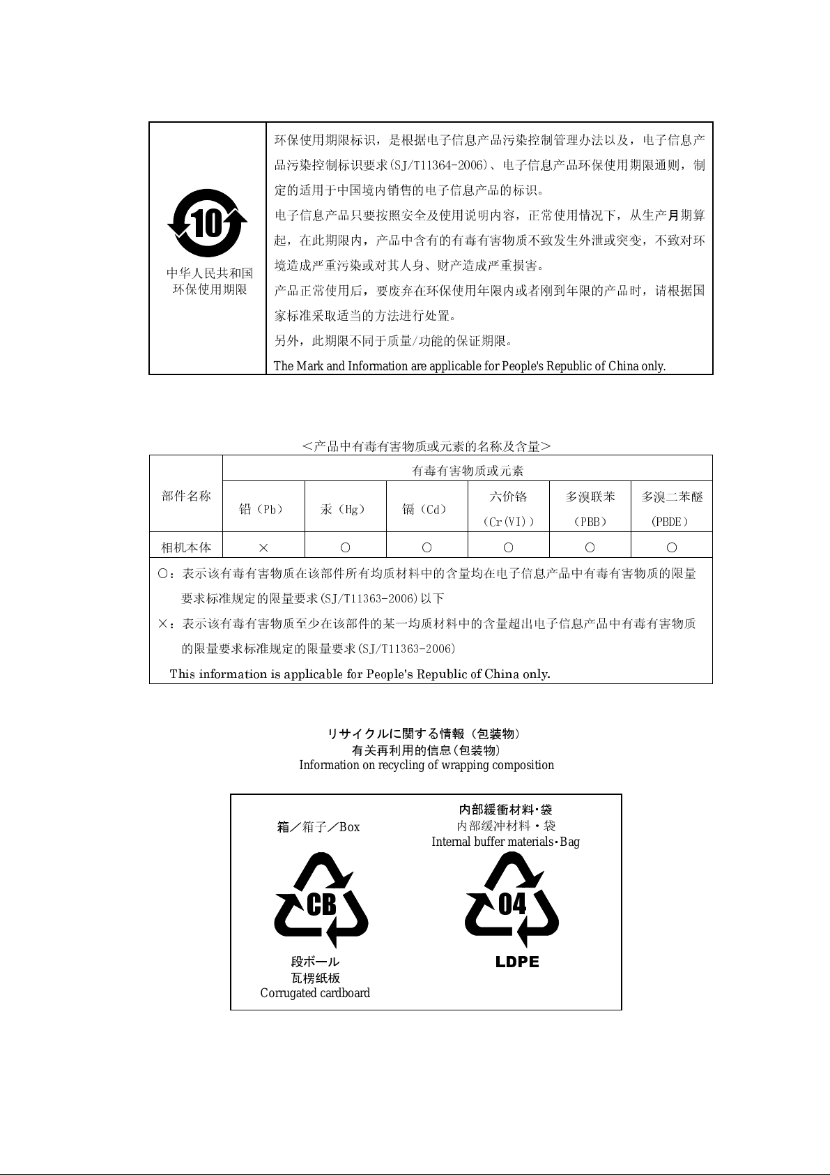
环保使用期限标识,是根据电子信息产品污染控制管理办法以及,电子信息产
品污染控制标识要求(SJ/T11364-2006)、电子信息产品环保使用期限通则,制
定的适用于中国境内销售的电子信息产品的标识。
电子信息产品只要按照安全及使用说明内容,正常使用情况下,从生产月期算
起,在此期限内,产品中含有的有毒有害物质不致发生外泄或突变,不致对环
境造成严重污染或对其人身、财产造成严重损害。
产品正常使用后,要废弃在环保使用年限内或者刚到年限的产品时,请根据国
家标准采取适当的方法进行处置。
另外,此期限不同于质量/功能的保证期限。
The Mark and Information are applicable for People's Republic of China only.
<产品中有毒有害物质或元素的名称及含量>
有毒有害物质或元素
部件名称
相机本体
○:表示该有毒有害物质在该部件所有均质材料中的含量均在电子信息产品中有毒有害物质的限量
要求标准规定的限量要求(SJ/T11363-2006)以下
×:表示该有毒有害物质至少在该部件的某一均质材料中的含量超出电子信息产品中有毒有害物质
的限量要求标准规定的限量要求(SJ/T11363-2006)
This information is applicable for People's Republic of China only.
铅(Pb) 汞(Hg) 镉(Cd)
× ○ ○ ○ ○ ○
リサイクルに関する情報(包装物)
有关再利用的信息(包装物)
Information on recycling of wrapping composition
六价铬
(Cr(VI))
多溴联苯
(PBB)
多溴二苯醚
(PBDE)
箱/箱子/
Box
内部緩衝材料・袋
内部缓冲材料·袋
CB
段ボール
瓦楞纸板
Corrugated cardboard
04
D4161841C
Page 9

1. Overview
This CCD color camera is a high-resolution color camera that features all pixel readout mode 1/1.8 CCD.
Model Power Supply Interface
CSCU30CC18 Camera Link Connector
CSCU30CC18-01 I/O Connector
(Power over Camera Link)
PoCL
non-PoCL
(Camera Link)
2. Features
(1)
High resolution
Bayer array high pixel density CCD (number of effective pixels 2.01 M, number of total pixels 2.11 M) is used.
(2)
Square grids
The CCD pixels arrayed in square grids facilitates computation for image processing.
(3)
Full-frame shutter
Since all pixels are output even by shutter operation, high resolution can be achieved, without deteriorating the
vertical resolution.
(4)
Camera link interface (power supply type) PoCL
The interface for image output and camera control complies with the camera link standard.
By using a camera link frame grabber board for camera link of possible power supplies, the shot image can be
transferred to PC at high speed, various camera controls can be performed from PC, and the power supply of the
camera can be supplied with one cable. The camera link model that is not the power supply type is
CSCU30BC18-01.
(5)
All-pixel readout mode (normal mode)
All pixel signals (in the effective area) are output in approximately 1/30 second.
(6)
Programmable partial scan mode
Partial scan within the range arbitrary from 50 lines to 1236 lines is possible.
(7)
High-speed draft readout mode
By reading 2 lines from every 8 lines, all signals in the effective area are output in approximately in 1/89 second.
(8)
Random trigger shutter
By external trigger signal input, the shot image can be grabbed at an arbitrary timing.
(9)
Multiple-shutter
By external trigger signal input, the shot image can be grabbed at an arbitrary timing and the accumulated shot
images can be output at an arbitrary timing.
Rev 3.0
3. Configuration
(1) Camera body·················································································1
(2) Accessories
Instruction Manual (Japanese)····················································1
Instruction Manual (English)······················································1
1
D4161841C
Page 10
4. Optional parts
(1) Power cable Model name: CPRC3700-**
(2) Camera Link cable For the cable for PoCL, please contact the cable manufacturer.
(3) Camera mounting kit Model name: CPT4000CL
(4) Camera adapter Model name: CA130C
*NOTE: Application software is not supplied as a standard item.
Notes on optional parts and compliance with safety standard conditions:
We assure the compliance of this camera with the safety standard when it is used in combination with the
optional parts listed above.
If you use the camera in combination with parts other than specified by our company, you are responsible
for finally confirming the compliance with the safety standard by using the entire machine/equipment.
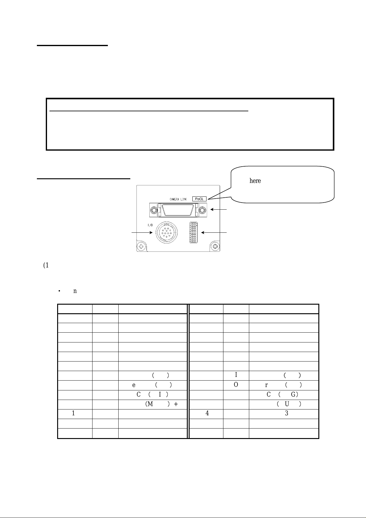
5. Name of Each Parts
PoCL
CSCU30CC18 (PoCL):
There is "PoCL" display.
CSCU30CC18-01 (Non-PoCL):
There is NOT "PoCL" display.
Rev 3.0
(1)
I/O
(2)(3)
(1)
Video output/controlling connector (Camera Link Base Configuration) CAMERA LINK
Outputs video signals and VALID, based on the camera link standard LVDS.
This connector is connected to the frame grabber board, image processing device and others.
・
Connector model: DR 26-PIN connector 10226-2210PE (manufactured by 3M).
Pin No. I/O Signal Name Pin No. I/O Signal Name
1 I(-) +12V (GND) 14 - GND
2 O Tx OUT0- 15 O Tx OUT0+
3 O Tx OUT1- 16 O Tx OUT1+
4 O Tx OUT2- 17 O Tx OUT2+
5 O Tx CLK OUT- 18 O Tx CLK OUT+
6 O Tx OUT3- 19 O Tx OUT3+
7 I
8 O
9 I
10 I
11 I CC3- 24 I CC3+
12 I CC4+ 25 I CC413 - GND 26 I(-) +12V (GND)
Ser TC(RxD)+
Ser TFG(TxD)-
CC1(TRIG)-
CC2(MULTI)+
20 I
21 O
22 I
23 I
Ser TC(RxD)-
Ser TFG(TxD)+
CC1(TRIG)+
CC2(MULTI)-
Please 1PIN and 26PIN must become power supplies, and match the camera link cable and grabber board for
PoCL and use it. Please note that they become GND in camera link model.
2
D4161841C
Page 11
Rev 3.0
(2) DIP switches
Used for various setting. For more information how to set the dip switches, see Chapter 8 "Dip Switch Setting"
(on page 5).
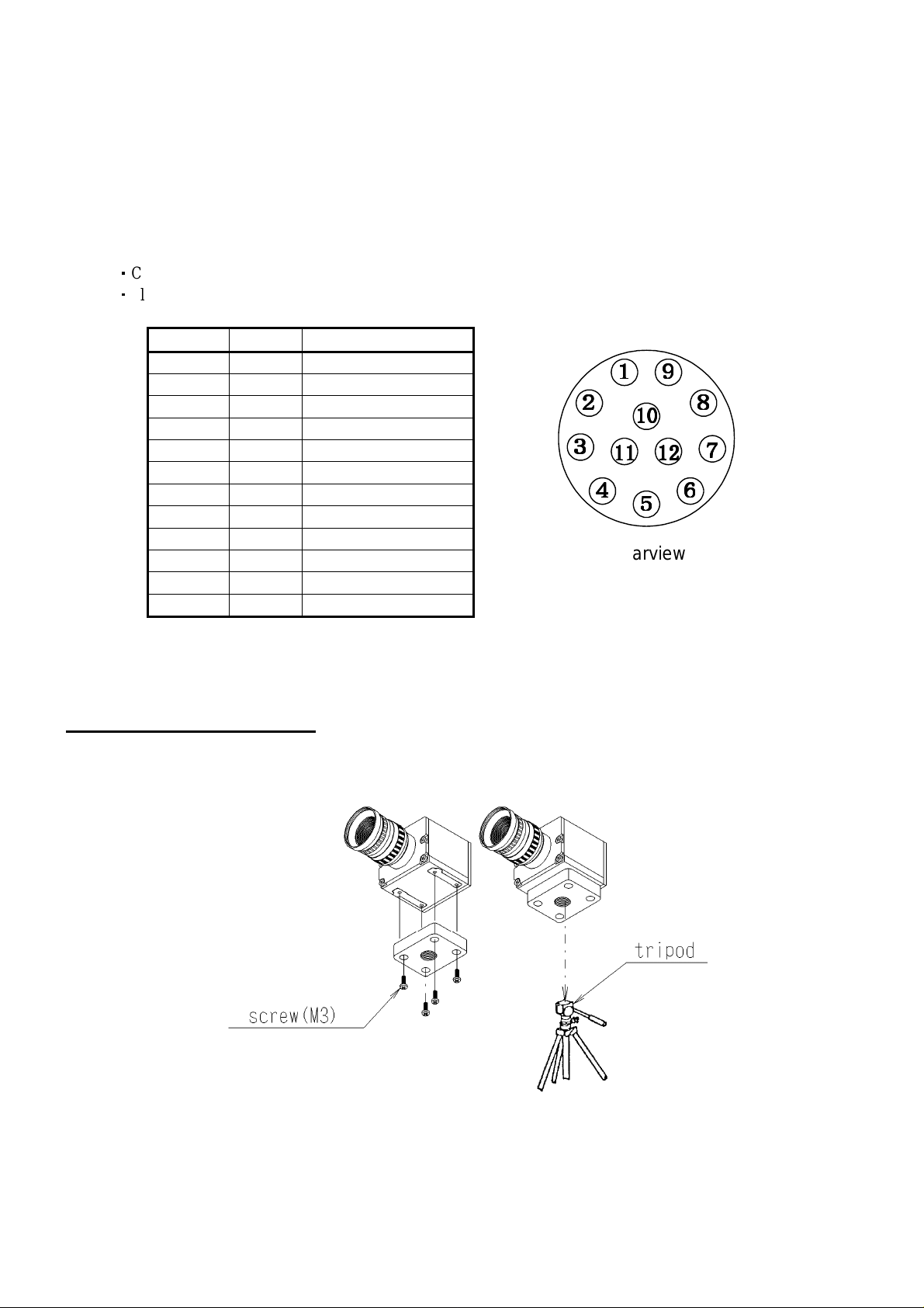
(3)
Connector for power supply and sync signal input/output I/O
This is a terminal used for power supply to the camera. This connector is connected to the power supply unit.
In addition, this connector is used for sync signal (WEN signal) output and external trigger signal input.
・
Connector (Camera side) : HR10A-10R-12PB (Manufactured by HIROSE DENKI)
・
Plug (Cable side) : HR10A-10P-12S (Manufactured by HIROSE DENKI) or equivalents
Pin No. I/O Signal Name
1
2 -(I)
3
4
5
6
7
8
9
10 O WEN
11 - TRIG
12
Because the power supply is done from the camera link cable, 2PIN is opened. Please note that they
become +12v in camera link model.
-
-
-
-
-
-
-
-
-
GND
N.C.(+12V)
GND
N.C.
GND
N.C.
N.C.
GND
N.C.
GND
1111
9999
2222
3333
4444
11
11
1111
10
10
1010
12
12
1212
8888
7777
6666
5555
Rearview
6. Installing the camera
(1) When you fix the camera with a tripod stand screw (1/4-20UNC), use an optional mounting tab.
When you fix the camera by using the mounting screw hole on the camera body, use an M3 screw (6 mm or less for the
(2)
portion to be inserted into the inside of the camera body).
3
D4161841C
Page 12
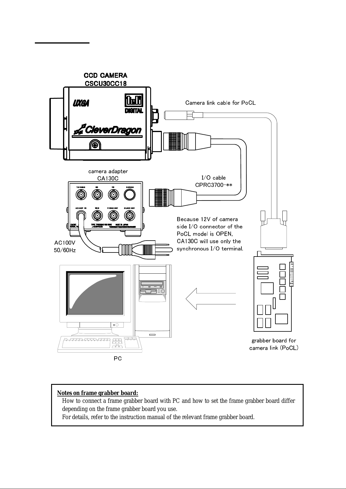
7. Connection
Connect this camera as shown in the figure below.
(The figure below shows an example of connection. For details, contact our sales representative.)
CCD CAMERA
CCD CAMERA
CCD CAMERACCD CAMERA
CSCU30CC18
CSCU30CC18
CSCU30CC18CSCU30CC18
Camera link cable for PoCL
camera adapter
CA130C
I/O cable
CPRC3700-**
Rev 3.0
Because 12V of camera
side I/O connector of the
PoCL model is OPEN,
AC100V
50/60Hz
PC
CA130C will use only the
synchronous I/O terminal.
grabber board for
camera link (PoCL)
Notes on frame grabber board:
How to connect a frame grabber board with PC and how to set the frame grabber board differ
depending on the frame grabber board you use.
For details, refer to the instruction manual of the relevant frame grabber board.
4
D4161841C
Page 13

8. DIP switch setting
By using the DIP switches on the back surface of the camera body, you can set serial transmission speed and
memory readout for when the power supply is turned on.
If you change the switch setting after the power supply is turned on, the change is not reflected.
Rev 3.0
1
2
3
4
5
6
7
8
9
10
O
N
Firm update
Transmission speed setting
Memory readout setting
Not used
(1) Transmission speed setting
You can set the speed of serial transmission by camera link.
SW2 SW3 Transmission speed
OFF OFF 9600 bps
ON OFF 19200 bps
OFF ON 38400 bps
(2) Memory readout setting
You can set the number of the setting value saving memory bank to be called when the power supply is turned on.
The memory consists of 4 banks.
SW4 SW5 Memory number
OFF OFF 0
ON OFF 1
OFF ON 2
ON ON 3
(3) Firm update
It is a changeover switch for the CPU firm in the camera update. Please use it by turning off usually.
5
D4161841C
Page 14

Rev 3.0
9. Functions
By accessing the camera register published on the camera link I/F, you can control/set each function.
Since access to the camera register is performed via the frame grabber board, the controlling and setting methods
differ depending on the frame grabber board you use. For details, refer to the instruction manual of the relevant
frame grabber board or contact our sales representative.
This instruction manual describes the specifications in the case where the camera register is directly connected by
serial transmission over the camera link interface.
9.1 Explanation of Each Function
(1) Register setting value updating
The changed register setting value is reflected on the camera operation.
Only writing a value in each register does not cause the value to be reflected on the camera operation.
Register value updating must be executed before the changed setting value can be reflected on the camera
action.
To save the setting value in memory, the register setting value must be updated beforehand. Otherwise, an
execution error occurs and the setting value is unable to be saved in memory.
(2) Readout mode
Video is output from the camera link connector. The output video can be grabbed by the frame grabber board.
The frame rate and resolution of output images that this model supports are as follows:
1) All pixel readout : Approximately 30 fps / 1628(H) x 1236(V)
2) Partial scan : Approximately 30 to 183 fps / 1628(H) x 552(V) to 1236(V)
3) High-speed draft readout : Approximately 89 fps / 1628(H) x 309(V)
1) All pixel readout
Address:0x70, Bit:0, Value:0 and Address:0x81, Bit:0, Value:0
Reads out all pixels in about 1/30 second.
Address:0x6E, Bit:0, Value:1
1250H
FVAL
LVAL
DVAL
DATA OUT
1234567
8
1236
1235
1234
6
D4161841C
Page 15

2) Programmable partial scan
A range arbitrary from 50 lines to 1236 lines can be read. The frame rate can be raised to 183fps or less by
skipping it at high speed excluding an effective area.
When the frame rate of a partial scanning exceeds it when the shutter mode is switched from normality
(internal synchronization) to the partial scanning mode, more high-speed than the setting of the speed of
the shutter it is changed at the speed of the shutter matched to the frame rate.
・
Starting position of effective line
Starting position (Partial V Start) of an effective line can be set.
・
Number of effective lines
Number (Partial Height) of effective lines can be set.
The frame rate is obtained in the following calculations.
3
FrameRate
+=
+
However, it assumes below the decimal point to be a round-down in {}.
Example:530 effective lines (60fps) and start 353 line eyes(center partial)
Register setting: Partial Height = 530, Partial V Start = 352
FVAL
LVAL
DVAL
Address:0x70, Bit:0, Value:0 and Address:0x81, Bit:0, Value:1
Address:0x84, Bit:0 to 7, and Address:0x85, Bit:0 to 2, Value:0 to 1186
Address:0x88, Bit:0 to 7, and Address:0x89, Bit:0 to 2, Value:50 to 1236
StartVPartial
8
15__
+
( )
8
+
+
HeightPartialStartVPartial
625H
_2
HeightPartial
1
−
13___1236
++−
1
−
×
1072
×
1920
6
Rev 3.0
353
355
356
357
358
359
DATA OUT
Skipped lines : 352 line
Effective lines : 530 line
Skipped lines : 354 line
< Example of calculating frame rate for the above-mentioned >
FrameRate
=
3
+=
{ } { }
[ ]
=
[ ]
354
15352
+
8
1072
×
+
×
5302
+
6
1072
+
=
192044530473
×+++
882
881
880
High-speed transfer : 44 line
+
Normal-speed transfer : 3 line
Effective lines :
High-speed transfer : 44 line
( )
135303521236
++−
−
8
1920875.44530875.473
×+++
66
1072
×
1920624
×
fps
60
=
530 line
1
−
1
×
1072
×
1920
6
7
D4161841C
Page 16

3) High-speed draft readout
Address:0x70, Bit:0, Value:1 and Address:0x81, Bit:0, Value:0
By reading 2 lines out of every 8 lines, reads out the whole valid area in approximately 1/89 seconds.
Control and setting of functions can be done by accessing the cam. When the frame rate of a partial scanning
exceeds it when the shutter mode is switched from normality (internal synchronization) or the partial
scanning mode to the draft mode, more high-speed than the setting of the speed of the shutter it is changed at
the speed of the shutter matched to the frame rate.
313H
FVAL
LVAL
DVAL
Rev 3.0
DATA OUT
16914172225
1233
1230
1225
Reading 2 lines out of every 8 lines in
the inside of a total of 1236 lines
Effective lines : 309 lines
8
D4161841C
Page 17

(3) Setup
Address:0x62, Bit:0 to 7, Value:50 to 255
You can set a setup level (pedestal).
Output Format
RGB / RAW 8bit
RAW 10bit
RAW 12bit
* In the factory setting, the setup is set to about 264LSB.
(4) Gain
Address:0x64, Bit:0 to 7, Value:0 to 150
You can set Gain (video gain).
Gain
(calculated value)
0 ~ +7 dB
Setup
(calculated value)
Setting range Calculation formula
0 ~31 LSB
0 ~124 LSB
0x00 ~ 0x1F
(0 ~ 31)
0 ~496 LSB
Setting range Calculation formula
0x00 ~ 0x4B
(0 ~ 75)
0.09375 x Gain
Rev 3.0
Setup
4 x Setup
16 x Setup
Notes on gain setting:
It is possible to set a maximum of +7 dB (Calculation value) but the warranty range for this product is 0
to +6 dB. When using this product, be sure to set a gain value within the warranty range.
And,Setting a too high gain value can increase noise. When you adjust the brightness of the shot image,
you are responsible for finally confirming the image quality by using the entire machine/equipment.
(5) White balance
There are two types of white balancing mode. You can set white balancing mode, according to the subject and
purpose.
1) OPWB (one-push auto white balance)
Address:0x74, Bit:0, Value:1 and Address:0x77, Bit:0, Value:1
When you execute OPWB, the white balance is automatically adjusted. After automatic adjustment, the
adjusted white balance is held. Execute OPWB, with a white subject picked up on the entire screen.
2) MANUAL (manual white balance)
Address:0x74, Bit:0, Value:0 and Address:0x75, Bit:0 to7, Value:0 to 255
In the manual white balance mode, the white balance can be adjusted manually in two ways: by preset
setting or by user setting (the user sets the R-gain and B-gain individually).
The preset setting can be selected from 6 fixed color temperatures (3000 K, 3700 K, 4000 K, 4500 K,
5500 K and 6500 K)
If you want to adjust the white balance more accurately, enter the user manual setting mode and set
R-gain and B-gain individually.
R-gain setting
B-gain setting
Address:0x78 and 0x79, Bit:0 to 7 and 0 to 2, Value:0 to 1535
Address:0x7A and 0x7B, Bit:0 to 7 and 0 to 2, Value:0 to 1535
(6) Gamma
Address:0x7D, Bit:0, Value:0 to 1
You can set gamma correction ON/OFF.
* When gamma correction is ON, the user cannot adjust the correction amount.
(7) Masking correction
Address:0x7E, Bit:0, Value:0 to 1
You can set masking correction ON/OFF. When masking correction is ON, the hue of images is corrected so that
it will be natural.
* When gamma correction is ON, the user cannot adjust the correction amount.
9
D4161841C
Page 18

(8) Electronic shutter
Address:0x68, Bit:0 to 7, and Address:0x69, Bit:0 to 2, Value:0 to 2047
You can set the shutter speed. The setting range differs depending on the output mode.
Readout mode
All pixel readout
Partial scan
High-speed draft readout
Shutter speed
(calculated value)
1/30 ~ 1/65,934 s
1/30 ~ 1/65,934 s
1/89 ~ 1/65,934 s
Setting range
0x4E1 ~ 0x000
(1249 ~ 0)
0x4E1 ~ 0x000
(
1249 ~ 0)
0x138 ~ 0x000
(312 ~ 0)
(1092 CLK + 1920 CLK x Shutter Speed) / 72 MHz
(1092 CLK + 2568 CLK x Shutter Speed) / 72 MHz
<For example, when you set shutter speed in 1/200 s (at All pixel readout, Partial scan)>
(1092 CLK + 1920 CLK x Shutter Speed) / 72 MHz = 1/200 s
1092+1920 x Shutter speed = 36x106 / 200
1920 x Shutter speed = 72x106 / 200 - 1092
∴∴∴∴
Shutter speed = (72x106 / 200 – 1092) / 1920 = 186.931...
≑≑≑≑
187 = 0x0BB
when you set shutter speed in 1/200 s, Please send a write command as follows.
(1) to write data 0xBB to address 0x68, to write data 0x00 to address 0x69.
(2) to write data 0x01 to address 0x6E
Rev 3.0
Calculation formula
10
D4161841C
Page 19

(9) Random trigger shutter
Address:0x6A, Bit:0, Value:1
In the random trigger shutter mode, you can shoot and grab an image at an arbitrary timing by trigger signal input
from the external.
・
External trigger signals can be input either from the camera link I/F CC1 or I/O connector.
・
If polarity is set to negative polarity, exposure starts at the falling edge of the trigger.
・
The random trigger shutter of this camera can be operated in two types of mode: fixed mode and pulse
Address:0x6A, Bit:1
width mode. How to determine the exposure time differs depending on the mode.
1) Fixed mode
・
The exposure time is determined by the setting value for the shutter speed.
・
FVAL is output in sync with the first LVAL after the end of exposure time.
Address:0x6B, Bit:0, Value:0
Rev 3.0
2) Pulse width mode
・
The exposure time is determined by the pulse width (exposure time = pulse width + approximately 14μs).
・
Set a pulse width of 1H (approximately 26.7μs) or more.
・
FVAL is output in sync with the first LVAL after the end of exposure time.
Address:0x6B, Bit:0, Value:1
Notes of trigger mode:
When the interval of the input trigger signal is extremely short, or when the trigger signal is noisy, there
is a possibility of causing the malfunction. In this case, please input a proper trigger signal.
11
D4161841C
Page 20

(10) Multiple-shutter mode
Address:0x66, Bit:0, Value:1
In the multiple-shutter mode, video is output in sync with a MULTI signal from the external after the end of
exposure time.
・
Valid only when the random trigger shutter mode is ON.
・
MULTI signals can be input from the camera link I/F CC2.
・
If exposure is executed several times before MULTI signal input, the images are output superposed.
・
The exposure time is determined by the random trigger shutter mode setting and its determination method.
・
The pulse width must be set to negative polarity and 1H (approximately 26.7μs) to 10 ms.
・
FVAL is output in sync with the first LVAL after the end of MULTI signal input.
TRIG
MULTI
A B
CCD
FVAL
LVAL
DVAL
DATA OUT
A + B
Rev 3.0
Notes on multiple-shutter:
An image has been stored to CCD device until a MULTI signal is inputted and it begins to read out
image after CCD is exposed. Therefore, an image may degenerate step by step when an image is stored
to CCD device for a long time.
And, Electric charge is superimposed in CCD device when the multiplex exposure. Therefore, CCD will
flood with electric charge when electric charge is over superimposed in CCD device. Consequently
vertical stripes noise will appear. At that time please stop using spotlight and dimmer for example close
the iris.
12
D4161841C
Page 21

Rev 3.0
(11) Restart reset mode
Address:0x6A, Bit:4, Value:1
In the start reset mode, it takes a picture of the image according to arbitrary timing by the VD signal input from
the outside, and it is possible to take it. A low-speed speed of the shutter can be easily set in this mode.
・External VD signal can be input from either camera link I/F CC1 or 11 I/O connector pins.
・The interval of external VD signal becomes the speed of the shutter (exposure time).
・Peculiar timing to internal makes horizontal, driving timing LVAL asynchronous from external VD signal.
・The image output is output to the input timing of external VD signal delaying 1.0H or less.
External VD input
CCD exposure
Image output
FVAL
13
D4161841C
Page 22

(12) Setting value memory
Each setting value can be saved in the memory inside the camera.
・
The contents of the memory is held even after the power supply is turned off.
・
The memory consists of 4 banks. For each table, you can save/readout the setting value independently, as well
as reset the setting value to the initial factory setting.
・
You can set the number of the memory bank to be read out when the power supply is turned on, by using the
relevant dip switch on the back surface of the main body.
1) Memory save
・
When you write to the register the number of the memory bank to which the setting value is to be saved, the
Address:0x51, Bit:0 to 1, Value:0 to 3
setting value of each register is saved in the internal memory.
・
If you have not executed "Update" after changing the setting value (reset address 0x6E to 0x01), an execution
error occurs and the setting value is not saved in the memory. Be sure to execute "Update" before saving the
setting value.
2) Memory readout
・
When you write to the register the number of the memory bank from which the setting value is to be read out,
Address:0x52, Bit:0 to 1, Value:0 to 3
the setting value is read out from the internal memory and set.
3) Memory reset
・
When you write to the register the number of the memory bank to be reset, the initial factory setting value is
Address:0x53, Bit:0 to 1, Value:0 to 3
read out from the internal memory and set.
(13) RAW Output bit
Address:0x90, Bit:0 to 1, Value:0 to 2
You can set gray scale per pixel. The initial factory setting is 12 bits.
(14) Output format
Address:0x92, Bit:0, Value:0 to 1
You can set RGB(24bit) / RAW (12bit / 10bit / 8bit) output. The initial factory setting is RGB(24bit) output.
Rev 3.0
14
D4161841C
Page 23

9.2 Communication protocol
This camera uses the communication protocol of our standard method (where, parameters are set for the
camera-internal registers).
In command transmission/receipt, the address and data in hexadecimal representation are converted to ASCII.
In addition, all alphabetical characters must be uppercase characters.
(1) Writing to the register
To write data to a register, send a write command as follows.
STX (0x02) Data UpperAddress LowerAddress Upper Data Lower ETX (0x03)
For example, to write data 0x38 to address 0x64, send a write command as follows.
STX (0x02) "3"(0x33)"4"(0x34)"6"(0x36) "8"(0x38) ETX (0x03)
The camera responds to the write command as follows.
STX (0x02) ACK(0x06) ETX (0x03)
Rev 3.0
STX (0x02) NAK(0x15) ETX (0x03)
*When you let camera operation reflect the changed register setting, Please you write in address 0x6E at 0x01
by all means, and update it.
(2) Reading the register
To read data from the register, send "R "Q" following the address.
For example, to read data from address 0x6A, send a read command as follows.
STX (0x02) "R"(0x52)"A"(0x41)"6"(0x36) "Q"(0x51) ETX (0x03)
The camera responds to the read command as follows.
STX (0x02) Data Upper Data Lower ETX (0x03)
15
D4161841C
Page 24

9.3 Register Map
Adr
Base Registers
Self Check
Registers
Memory
Resisters
0x00
|
0x0F
0x10
|
0x1F
0x20
|
0x2F
0x30
|
0x37
0x38
|
0x3F
0x40
0x41
0x42
|
0x4F
0x50
0x51
0x52
0x53
0x54
|
0x5F
Name Bit7 Bit6 Bit5 Bit4 Bit3 Bit2 Bit1 Bit0 Default
Vendor Name
(Read Only)
Model Name
(Read Only)
Serial Number
(Read Only)
CPU Version
(Read Only)
FPGA Version
(Read Only)
Self Check
(Read Only)
Status
(Read Only)
Reserved Reserved -
Memory
Information
(Read Only)
Memory Save
(Write Only)
Memory Load
(Write Only)
Memory Reset
(Write Only)
Reserved Reserved -
- - - - - -
- - - - - -
- - - - - -
Number of Memory Bank in This Camera (0x04) 0x04
“TOSHIBA TELI”
“CSCU30CC18”
Serial Number
ex. “V1.01.01”
ex. “V1.01.01”
Self Check Result 0x00
Status Code 0x00
Save Bank
Number
(0x00 ~ 0x03)
Load Bank
Number
(0x00 ~ 0x03)
Reset Bank
Number
~
(0x00
0x03)
Rev 3.0
←
←
←
←
←
-
-
-
16
D4161841C
Page 25

Rev 3.0
Adr
Name Bit7 Bit6 Bit5 Bit4 Bit3 Bit2 Bit1 Bit0 Default
Base Function
Registers
0x60
0x61
0x62
0x63
0x64
0x65
0x66 Multiple Shutter - - - - - - -
0x67
0x68 Shutter Speed(L)
0x69 Shutter Speed(U) - - - - -
0x6A
0x6B Random Mode - - - - - - -
0x6C
0x6D
0x6E
0x6F
0x70
0x71
|
0x73
Reserved Reserved -
Reserved Reserved -
Setup
Reserved Reserved -
Gain
Reserved Reserved -
Reserved Reserved -
Shutter Mode - - -
Reserved Reserved -
Reserved Reserved -
Update
(Write Only)
Reserved Reserved -
Draft Mode - - - - - - -
Reserved Reserved -
- - - - - - - 1:EXEC
Setup (0x00 ~ 0x31)
Gain (0x00 ~ 0x4B)
Shutter Speed (0x000 ~ 0x7FF)
Restart
Reset
1:ON
0:OFF
- -
Polarity
1:POS
0:NEG
1:ON
0:OFF
Random
1:ON
0:OFF
1:PLS
0:FIX
1:ON
0:OFF
0x10
0x00
0x00
0x4E1
0x00
0x00
-
0x00
17
D4161841C
Page 26

Rev 3.0
Adr
Base Function
Registers
Name Bit7 Bit6 Bit5 Bit4 Bit3 Bit2 Bit1 Bit0 Default
0x74
0x75 Manual WB Temp.
0x76
0x77
0x78
0x79
0x7A
0x7B
0x7C
0x7D
WB Mode - - - - - - -
Reserved Reserved -
OPWB
(Write Only)
User Manual WB
R Gain(L)
User Manual WB
R Gain(U)
User Manual WB
B Gain(L)
User Manual WB
B Gain(U)
Reserved Reserved -
Gamma - - - - - - -
1:OPWB
0:MANU 0x00
0x1E: 3000K
0x25: 3700K
0x28: 4000K
0x2D: 4500K
0x37: 5500K
0x41: 6500K
0xFF: User Manual WB
- - - - - - - 1:EXEC
User Manual WB R Gain (0x000 ~ 0x5FF)
- - - - -
User Manual WB B Gain (0x000 ~ 0x5FF)
- - - - -
1:ON
0:OFF 0x01
0xFF
-
-
-
1:ON
0x7E
0x7F
Masking - - - - - - -
Reserved Reserved -
0:OFF 0x00
18
D4161841C
Page 27

Rev 3.0
Base Function
Registers
Expansion
Registers
Adr
0x80
0x81
0x82
0x83
0x84 Partial V Start(L)
0x85 Partial V Start(U) - - - - -
0x86
0x87
0x88 Partial Height(L)
0x89 Partial Height(U) - - - - -
0x8A
0x8F
0x90
0x91
0x92
0x93
0x94
0x95
0x96
0xFF
|
|
|
Output Format - - - - - -
|
Expansion Status
|
Name Bit7 Bit6 Bit5 Bit4 Bit3 Bit2 Bit1 Bit0 Default
Reserved Reserved -
Partial Scan - - - - - - -
Reserved Reserved -
Partial V Start (0x000 ~ 0x4A2)
Reserved Reserved -
Partial Height (0x1E ~ 0x4D4)
Reserved Reserved -
Output Bit - - - - - -
Reserved Reserved
Reserved Reserved -
(Read Only)
Reserved Reserved -
Expansion Status 0x00
1:ON
0:OFF
0x00:12bit
0x01:10bit
0x02: 8bit
1:RAW
0:RGB
0x00
0x160
0x212
0x00
0x00
19
D4161841C
Page 28

9.4 Error status
If NAK is returned to the sent command, you can obtain detailed information on the error by accessing the
status register.
Status code
Rev 3.0
Error type Details of error
No Error
Status Register Accessed
Communication Error
Addressing Error
Save Data Error
Mode Setting Error
Configuration Error
Hardware Error
The previous communication was executed
normally.
An attempt was made to read the Status
/Expansion Status register.
A communication error occurred.
The reserved area was accessed.
An attempt was made to write data to a
write-protected area.
An attempt was made to read data from a
read-protected area.
An attempt was made to perform Memory
Save before performing Update processing.
An attempt was made to write a mode
setting value other than specified.
An attempt was made to write a value that is
out of the specified range.
A hardware error was detected.
Status Code
(Addr. 0x41)
0x00 0x00
--- ---
0x01 0x00
0x10 0x00
0x10 0x01
0x10 0x02
0x11 0x00
0x20 0x00
0x30 0x00
0xFF 0x00
Expansion
Status
(Addr. 0x95)
20
D4161841C
Page 29

10. Before determining it as being a fault
If any trouble occurs in use, check the following first.
If the trouble persists, contact your distributor or our sales representatives.
Phenomena Check item
Cannot turn on power - Check the connection of the camera adapter and power cable.
Shooting image is not displayed
Frame drop occurs on shooting
image
Shooting image remains still - Check that the camera is not in the random trigger mode.
Cannot control camera from PC - Check the connection of the camera link cable.
- Check the connection of the camera link cable and camera cable.
- Check that the camera register settings are correct.
- Check that the dip switch settings are correct.
- Check that lens aperture is not closed.
- Check that the grabber board is installed and set up correctly.
- In the PCI bus system, a frame dropping may occur because the
transfer rate is too slow for the amount of data to be transferred. Ensure
that no frame dropping occurs with a grabber board and PC for PCI
Express x4.
- If more than one boards are installed in the PCI slots, remove the other
boards.
- Check the setting of the grabber board.
- Check the connection of the camera link cable.
- Check the dip switch setting (communication speed setting).
- Check that the grabber board is installed and set up correctly.
Rev 3.0
21
D4161841C
Page 30

11. Specifications
[Electrical specification]
(1) Imager Interline CCD
・
Number of total pixels 1688 (H) x 1248 (V)
・
Number of effective pixels 1628 (H) x 1236 (V)
・
Pixel size 4.4µm (H) x 4.4µm (V)
・
Optical size 1/1.8 type
・
Color filter RGB primary color mosaic-on-tip color filter
(2) Scan method Progressive
(3) Aspect ratio 4:3
(4) Synchronization method Internal synchronization
(5) Standard subject illuminance 2400 lx, F8, 5000 K (Gamma On)
(6) Minimum subject illuminance 35 lx
(
F1.4, GAIN MAX, all pixel readout, video level 50 %, Gamma On)
(7) Video output Compliant with the camera link standard.
・
Data RGB 24bit / RAW 12bit / RAW 10bit / RAW 8bit switching
(initial factory setting: RGB)
RAW pixel array
Red Green
Green Blue
・
Readout mode
All pixel readout Approximately 30 fps / 1628(H) x 1236(V)
Partial scan Approximately 30 fps to 183fps / 1628(H) x 50 to 1236(V)
High-speed draft readout Approximately 89 fps / 1628(H) x 309(V)
(8) Gain 0 to +6 dB (75 levels) (initial factory setting: 0 dB)
(9) Setup 0 to 31 (32 levels) (initial factory setting: 16 LSB (calculated value) )
(10) White balance OPWB/MANUAL switching (initial factory setting: MANUAL)
Effective range 2500 K to 6500 K
・
OPWB
Effective area Full screen
・
MANUAL
Preset value 3000 K, 3700 K, 4000 K, 4500 K, 5500 K, 6500 K
User setting R-gain and B-gain can be set independently.
(11) Gamma correction ON(Gamma=0.65)/OFF(Gamma=1) switching (initial factory setting: ON)
(12) Masking correction ON/OFF switching (initial factory setting: OFF)
(13) Power supply voltage DC12 V (10.0 to 13.2V) (ripple 50 mV(p-p) or less)
(14) Power consumption Typical: Approximately 4.0 W (initial factory setting: All pixel readout)
Max: Approximately 4.5 W (50lines partial scan)
Rev 3.0
Notes on power consumption of PoCL:
Power consumption might exceed 4W in the partial scan mode. The PoCL model might not be able to
be started according to the supplied electricity of frame grabber board or length of the camera link
cable. I hope the examination to the non-PoCL model etc. in that case.
22
D4161841C
Page 31

[[[[
Electronic shutter specification
]]]]
(1) Shutter speed
・
Readout mode
All pixel readout 1/30 to 1/65,934 s (1250 levels)
Partial scan 1/30 to 1/65,934 s (1250 levels)
High-speed draft readout 1/89 to 1/65,934 s (313 levels)
(2) Random trigger shutter ON/OFF switching (initial factory setting: OFF)
・
Fixed mode The exposure time depends on the shutter speed setting.
・
Pulse width mode The exposure time depends on the pulse width.
※
When you input the following trigger signal to this camera for one frame period immediately after the trigger
signal input (When you continuously output the image), the noise might be generated in the image output.
The solution of the noise is not to input the following trigger for the image output period. The image output
period can be recognized based on the WEN output or the VD output. Please refer to the timing chart for one
frame period of each mode. Or, please refer to the FVAL signal.
(3) Multiple-shutter ON/OFF switching (initial factory setting: OFF)
Exposure by TRIG input, readout by MULTI input
* Enabled when random trigger shutter is ON.
(4) Restart reset ON/OFF switching (initial factory setting: OFF)
Rev 3.0
23
D4161841C
Page 32

[Internal sync signal specification]
(1) Driving frequency 72.000 MHz
(2) Scanning frequency
・
Readout mode
All pixel readout Horizontal :37.500 kHz
Vertical :30.000 Hz
Partial scan Horizontal :37.500 kHz
Vertical :30.193 Hz to 183.824Hz
High-speed draft readout Horizontal :28.037 kHz
Vertical :89.576 Hz
[[[[
Input signal specification
]]]]
(1) TRIG Camera link I/F and I/O connector input
・
Signal level (I/O input) TTL level
・
Polarity Positive/Negative polarity switching possible (initial factory setting: Negative)
・
Pulse width 26.7μs or more
(2) MULTI Camera link I/F input
・
Polarity Negative polarity
・
Pulse width 26.7μs to 10 ms
[Output signal specification]
(1) WEN I/O connector output
・
Signal level 4 V (p-p)
・
Polarity Positive polarity
・
Pulse width Approximately 26.7μs
(2) VD I/O connector output
・
Signal level 4 V (p-p)
・
Polarity Negative polarity
・
Pulse width Approximately 80μs
Rev 3.0
24
D4161841C
Page 33

[[[[
Dimensions
]]]]
(1) Lens mount C-mount
Notes on combination of C-mount lens:
Depending on the lens you use, the performance of the camera may not be brought out fully due
to the deterioration in resolution and brightness in the peripheral area, occurrence of a ghost,
aberration and others.When you check the combination between the lens and camera, be sure to
use the lens you actually use.
As for the C-mount lens used combining this camera, the projection distance from bottom of the
screw should use 9.5mm or less.
C-mount lens
Bottom of
the screw
9.5mm or less
(2) Flange back 17.526 mm
(3) Dimensions 54 mm (W) x 43 mm (H) x 59 mm (D)
(4) Mass Approximately 175 g
(5) Camera body grounding: insulation status
Conductive between circuit GND and camera body
[[[[
Operating ambient conditions
]]]]
(1) Performance assurance Temperature : 0 to 40°C
Humidity : 10 to 90% (no condensation)
(2) Operating assurance Temperature : -5 to 45°C
Humidity : 90% or less (no condensation)
(3) Storage environment Temperature : -20 to 60°C
Humidity : 10 to 90% (no condensation)
Rev 3.0
25
D4161841C
Page 34

[[[[
Typical spectral response
]]]]
The lens characteristics and light source characteristics is not reflected in table.
1.0
0.9
0.8
BLUE GREEN RED
0.7
e
s
n
0.6
o
p
s
e
R
0.5
e
v
i
t
a
0.4
l
e
R
0.3
0.2
Rev 3.0
0.1
0.0
400 450 500 550 600 650 700
Wave Length [nm]
[[[[
Applicable safety standards
]]]]
(1) EMC (Electro-Magnetic Compatibility)
EMI(Electro-Magnetic Interference) :EN61000-6-4 / 2001
EMS(Electro-Magnetic Susceptibility) :EN61000-6-2 / 2001
(2) FCC :FCC Part 15 Subpart B class A
[[[[
Communication specification
]]]]
(1) Communication speed 9600/19200/38400 bps
(2) Data bit 8
(3) Parity bit None
(4) Stop bit 1
(5) Handshake None
26
D4161841C
Page 35

[[[[
Timing chart
]]]]
(1) Horizontal timing
1) All pixel readout, Partial scan
LVAL
DVAL
DATA OUT
Rev 3.0
a b
c d
e
a = 185CLK b = 107CLK c = 292CLK d = 1628CLK e = 1920CLK
2) High-speed draft readout
LVAL
DVAL
DATA OUT
a b
a = 185CLK b = 755CLK c = 940CLK d = 1628CLK e = 2568CLK
c d
e
27
D4161841C
Page 36

(2) Vertical timing
1) All pixel readout
FVAL
LVAL
DVAL
DATA OUT
Rev 3.0
A
B
C
F
D
E
A = 3H B = 10H C = 13H D = 1236H E = 1H F = 1250H
2) Partial scan
FVAL
LVAL
DVAL
DATA OUT
A
A = 3H B = 10H C = 13H D = 1236H E = 1H F = 1250H
3) High-speed draft readout
FVAL
LVAL
DVAL
DATA OUT
A
C D
B
C
F
D
E
B
F
A = 3H B = 1H C = 4H D = 309H E = 0H F = 313H
28
D4161841C
Page 37

12. Guarantee
The term of a guarantee is one year after the product delivery.
If by any chance trouble by responsibility of our company occurs before an above period, TELI repairs it free of
charge.
During terms of a guarantee, when the trouble cause is the case of below, TELI charges the repair costs.
(1)
Troubles and the damages that causes by misuse, unsuitable repair or remodeling.
(2)
Distribution hazards like drops and vibrations after purchase. Troubles and damages by transportation.
(3)
Troubles and damages by fire, natural calamity (earthquake, storm and flood damage, thunderbolt), damages
from salty breeze, gas harm, abnormal voltage.
13. Repair
(1)
Condition for repair
Basically, has to return it to our company when the user requests us to repair product.
Beside that, customer should pay these expenses (travel expenses, camera disassembly technology costs) of
both customer and end user. Also customer should pay in themselves costs for return camera to us.
(2)
The period of repairing product
· Repair free of charge ... Refer to Clause 12.
· Charged repair ............. Basically, repair period is 7 years after the last production end of products.
Rev 3.0
29
D4161841C
Page 38

13. Outline Drawing
Rev 3.0
30
D4161841C
Page 39

NOTE
Rev 3.0
D4161841C
Page 40

Rev 3.0
Head Office
: 7-1, 4 chome, Asahigaoka, Hino-shi, Tokyo, 191-0065, Japan
(International Sales Department)
Phone : +81-42-589-8771
Fax : +81-42-589-8774
URL : http://www.toshiba-teli.co.jp/
Distributor
This product must be classified for disposal according to the laws of each country and municipal laws.
•
Information contained in this document is subject to change without prior notice.
•
D4161841C
 Loading...