

Page 1
Rev.1. 0
CCD COLOR CAMERA
Model CS5270B/CS5270BP
Instruction Manual
Thank you for purchasing our product.
Before using this CCD Color camera, please read through this instruction manual
carefully in order to use this product correctly and safely.
After reading, keep this instruction manual handy so that you can refer to,
whenever you need it.
Contents
Safety Precautions
1. Overview··································································································· 1
2. Features ····································································································· 1
3. Configuration ···························································································· 1
4. Optional parts···························································································· 2
5. Name of Each Parts··················································································· 2
6. Control of internal dip switches································································ 3
7. Connection ································································································ 5
8. How to set up your camera ······································································ 6
9. Specifications ··························································································· 7
10. How to mount your camera ···································································· 8
11. Outline Drawing······················································································ 9
Printed on recycled paper
D4161564A
Page 2
Safety Precautions
Before using this product, read these safety precautions carefully. Important information is shown in this
Instruction Manual to protect users from bodily injuries and property damages, and to enable them to use the
product safely and correctly.
Please be sure to thoroughly understand the meanings of the following signs and symbols before reading the main
text that follow, and observe the instructions given herein.
[Definition of Safety Signs]
Safety Signs Description
Rev.1. 0
WARNING
CAUTION
Notes *1: “Serious injury” refers to cases of loss of eyesight, wounds, burns (high or low temperature),
electric shock, broken bones, poisoning, etc., which leave after-effects or which require
hospitalization or a long period of outpatient treatment of cure.
*2: "Light to moderate injuries" refers to injuries, burns, electric shock etc. that do not require
hospitalization or long-term treatment.
*3: "Property damage" refers to cases of extensive damage involving damage to buildings,
equipment, farm animals, pet animals and other belongings.
[Explanation of Safety Symbols]
Safety Symbols Description
PROHIBITED
Indicates a potentially hazardous situation that may result in death or
serious injury (*1) in the event of improper handling.
Indicates a potentially hazardous situation that may result in light to
moderate injuries (*2) or only in property damage (*3)in the event of
improper handling.
This sign indicates PROHIBITION (Do not).
The content of prohibition is shown by a picture or words beside the
symbol.
MANDATORY
This sign indicates MANDATORY ACTION (You are required to do).
The content of action is shown by a picture or words beside the symbol.
D4161564A
Page 3
[General Handing]
Rev.1. 0
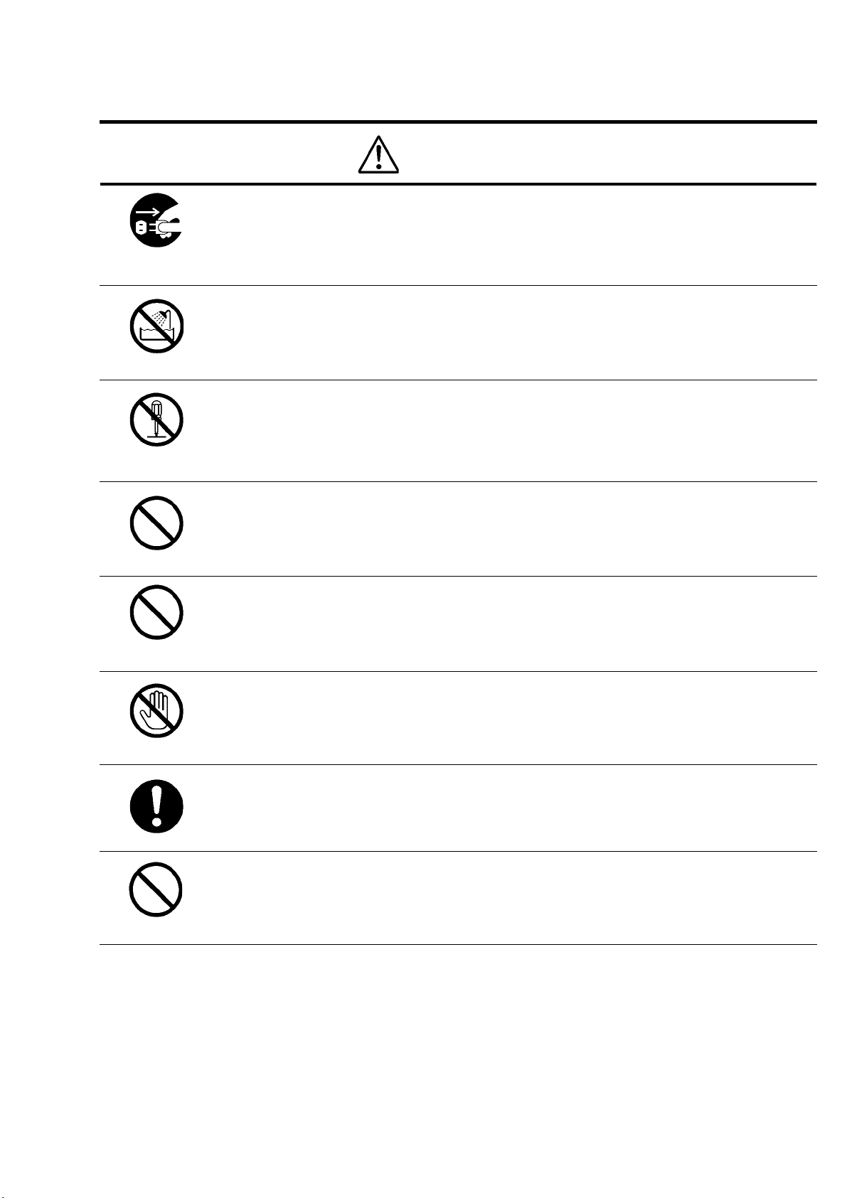
WARNING
unplug
Do not get wet
Never pull apart
Avoid
Avoid
Immediately cease use of the equipment in the event of abnormality or malfunction.
If abnormal conditions are present, such as smoke, a burning smell, ingress of water or foreign
matter, or if the equipment is dropped or malfunctions, fire or electric shock may result.
If such abnormalities occur, disconnect the power plug from the outlet and contact your sales
representative.
Do not use the equipment in locations subject to water splashes.
Otherwise, fire or electric shock may result.
Do not disassemble, repair, or modify the equipment.
Otherwise, fire or electric shock may result.
For internal repair, inspection, or cleaning, contact your sales representative.
Do not place anything on the equipment.
If metallic objects, liquid, or other foreign matter enters the equipment, fire or electric shock may
result.
Do not install the equipment in an unstable or inclined location or locations subject to
vibration or impact.
Otherwise, the equipment may topple over and cause personal injury.
Do not touch
Instruction
Avoid
During an electrical storm, do not touch the power cord or connection cable.
Otherwise, an electric shock may result.
Use the specified voltage.
Use of an unspecified voltage may result in fire or electric shock.
Do not be handled roughly, damaged, fabricated, bent forcefully, pulled, twisted, bundled,
placed under heavy objects or heated the power cord , connection cable.
Otherwise, fire or electric shock may result.
D4161564A
Page 4
[General Handing]
Rev.1. 0
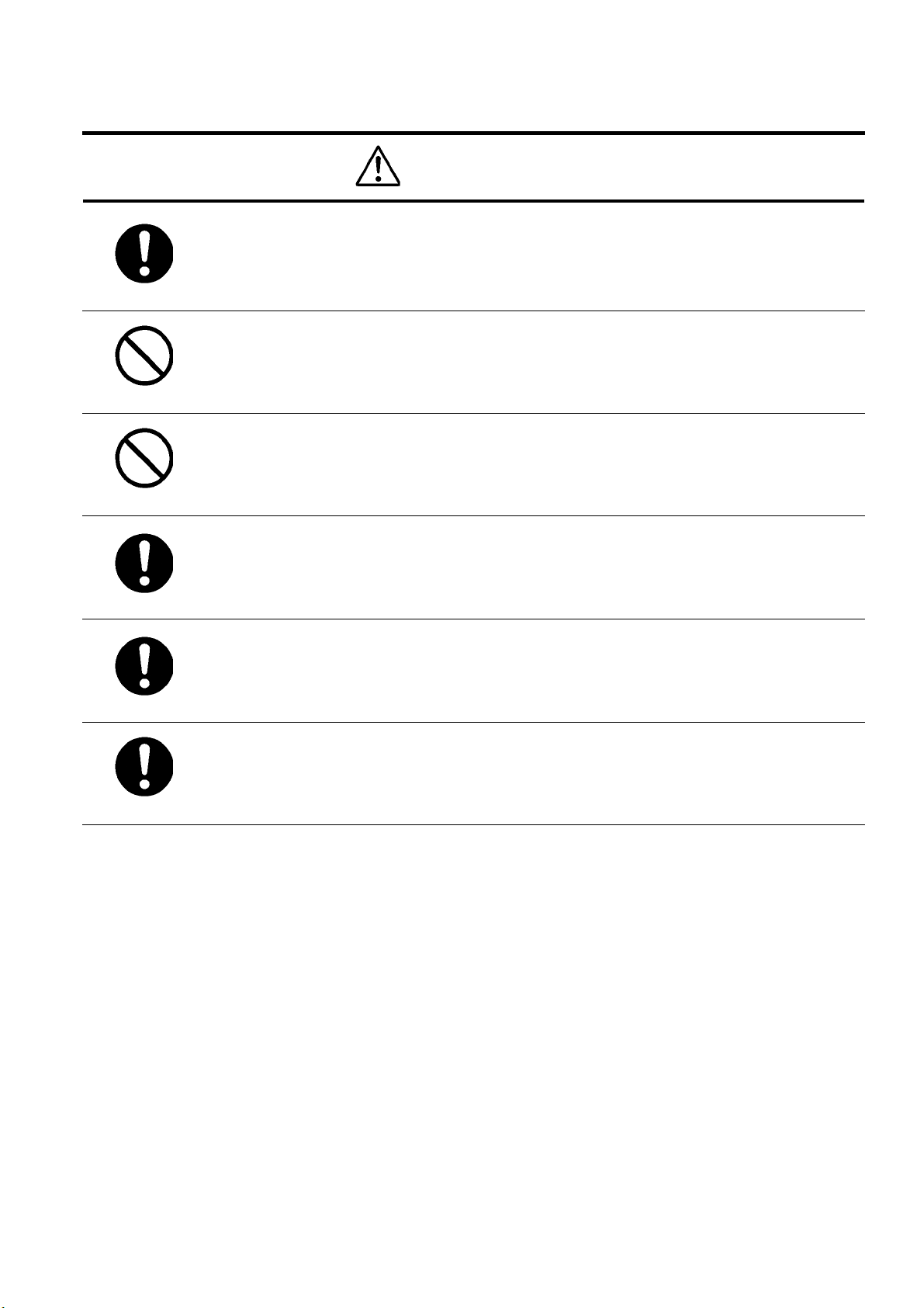
CAUTION
Instruction
Observe the following when installing the equipment:
· Do not cover the equipment with a cloth, etc.
· Do not place the equipment in a narrow location where heat is likely to accumulate.
Otherwise, heat will accumulate inside the equipment, possibly resulting in a fire.
Do not place the equipment in locations subject to high moisture, oil fumes, steam, or dust.
Otherwise, fire or electric shock may result.
Avoid
Do not install the equipment in locations exposed to direct sunlight or humidity.
Otherwise, the internal temperature of the equipment will rise, which may cause a fire.
Avoid
Use only specified DC power cables and connection cables.
Otherwise, fire or electric shock may result.
Instruction
When performing connection, turn off power.
When connecting the power cable or connection cable, turn off the equipment power.
Instruction
Instruction
Otherwise, fire or electric shock may result.
Contact your sales representative to request periodic inspection and cleaning (every
approx. five years).
Accumulation of dust inside the equipment may result in fire or electric shock.
For inspection and cleaning costs, contact your sales representative.
D4161564A
Page 5

CASES FOR INDEMNITY (LIMITED WARRANTY)
We shall be exempted from taking responsibility and held harmless for damage or losses incurred by the user in
the following cases.
In the case damage or losses are caused by fire, earthquake, or other acts of God, acts by a third party, deliberate
or accidental misuse by the user, or use under extreme operating conditions.
In the case of indirect, additional, consequential damages (loss of business interests, suspension of business
activities) are incurred as result of malfunction or non-function of the equipment, we shall be exempted from
responsibility for such damages.
In the case damage or losses are caused by failure to observe the information contained in the instructions in
this instruction manual and specifications.
In the case damage or losses are caused by use contrary to the instructions in this instruction manual and
specifications.
In the case damage or losses are caused by malfunction or other problems resulting from use of equipment or
software that is not specified.
Rev.1. 0
In the case damage or losses are caused by repair or modification conducted by the customer or any
unauthorized third party (such as an unauthorized service representative).
Expenses we bear on this product shall be limited to the individual price of the product.
RESTRICTION FOR USE
Should the equipment be used in the following conditions or environments, give consideration to safety
measures and inform us of such usage:
1. Use of the equipment in the conditions or environment contrary to those specified, or use outdoors.
2. Use of the equipment in applications expected to cause potential hazard to people or property, which
require special safety measures to be adopted.
This product can be used under diverse operating conditions. Determination of applicability of equipment or
devices concerned shall be determined after analysis or testing as necessary by the designer of such equipment
or devices, or personnel related to the specifications. Such designer or personnel shall assure the performance
and safety of the equipment or devices.
This product is not designed or manufactured to be used for control of equipment directly concerned with
human life (*1) or equipment relating to maintenance of public services/functions involving factors of
safety (*2). Therefore, the product shall not be used for such applications.
(*1): Equipment directly concerned with human life refers to.
· Medical equipment such as life-support systems, equipment for operating theaters.
· Exhaust control equipment for exhaust gases such as toxic fumes or smoke.
· Equipment mandatory to be installed by various laws and regulations such as the Fire Act or
Building Standard Law
· Equipment related to the above
(*2) :Equipment relating to maintenance of public services/functions involving factors of safety refers to.
· Traffic control systems for air transportation, railways, roads, or marine transportation
· Equipment for nuclear power generation
· Equipment related to the above
D4161564A
Page 6

Notes on using this product
Handle carefully
Do not drop the equipment or allow it to be subject to strong impact or vibration, as such action may cause
malfunctions. Further, do not damage the connection cable, since this may cause wire breakage.
Environmental operating conditions
Do not use the product in locations where the ambient temperature or humidity exceeds the specifications.
Otherwise, image quality may be degraded or internal components may be adversely affected. In particular, do
not use the product in areas exposed to direct sunlight. Moreover, during shooting under high temperatures,
vertical stripes or white spots (noise) may be produced, depending on the subject or camera conditions (such as
increased gain). However, such phenomena are not malfunctions.
Check a combination with the lens
Depending on the lens and lighting you use, an image is reflected as a ghost in the imaging area. However, this
is not because of a fault of the camera.
In addition, depending on the lens you use, the performance of the camera may not be brought out fully due to
deterioration in resolution and brightness in the peripheral area, aberration and others.
Be sure to check a combination with the camera by using the lens and lightning you actually use.
When installing a lens in the camera, make sure carefully that it is not tilted.
In addition, use a mounting screw free from defects and dirt. Otherwise, the camera may be unable to be
removed.
Do not shoot under intense light.
Avoid intense light such as spot lights on part of the screen because it may cause blooming or smears. If intense
light falls on the screen, vertical stripes may appear on the screen, but this is not a malfunction.
Rev.1. 0
Occurrence of moiré
If you shoot thin stripe patterns, moiré patterns (interference fringes) may appear. This is not a malfunction.
Occurrence of noise on the screen
If an intense magnetic or electromagnetic field is generated near the camera or connection cable, noise may be
generated on the screen. If this occurs, move the camera or the cable.
Handling of the protective cap
If the camera is not in use, attach the lens cap to the camera to protect the image pickup surface.
If the equipment is not to be used for a long duration
Turn off power to the camera for safety.
Maintenance
Turn off power to the equipment and wipe it with a dry cloth.
If it becomes severely contaminated, gently wipe the affected areas with a soft cloth dampened with diluted
neutral detergent. Never use alcohol, benzene, thinner, or other chemicals because such chemicals may damage
or discolor the paint and indications.
If the image pickup surface becomes dusty, contaminated, or scratched, consult your sales representative.
Disposal
When disposing of the camera, it may be necessary to disassemble it into separate parts, in accordance with the
laws and regulations of your country and/or municipality concerning environmental contamination.
D4161564A
Page 7

This equipment has been tested and found to comply with the limits for a class A digital device, pursuant
to Part 15 of the FCC Rules.
These limits are designed to provide reasonable protection against harmful interference when the
equipment is operated in a commercial environment.
This equipment generates, uses, and can radiate radio frequency energy and, if not installed and used in
accordance with the instruction manual, may cause harmful interference to radio communication.
Operation of this equipment in a residential area is likely to cause harmful interference in which case the
user will be require to correct the interference at his own expense.
Rev.1. 0
D4161564A
Page 8

1. Overview
The CS5270B/CS5270BP is a one-piece type (*) CCD color camera with a ultra-compact & light-weight body.
[*One-piece type : One integrated body made up of the camera head & the camera control unit]
2. Features
(1) The camera is driven by DC+12V.
(2) The ultra-compact & light-weight body is best suited for observation and other applications.
(3) Just with one push of this button, the camera will adjust its white-balance.
3. Configuration
(1) Camera body ················································································· 1
(2) Accessories
Instruction Manual (Japanese)···················································· 1
Rev.1. 0
D4161564A
Page 9

Rev.1. 0
④ ③ ⑤ ②
4. Optional parts
(1) Power cable Model name: CPRC5260D-**
(2) Camera mounting kit Model name: CPT8420
(3) Camera adapter Model name: CA5260
Notes on optional parts and compliance with safety standard conditions:
We assure the compliance of this camera with the safety standard when it is used in combination with the
optional parts listed above.
If you use the camera in combination with parts other than specified by our company, you are responsible
for finally confirming the compliance with the safety standard by using the entire machine/equipment.
5. Name of Each Parts
①WB
Just with one push of this button, the camera will adjust its white-balance when a subject’scolor temperature shifts. AWB is performed
during WB button push, and held (=HOLD) when the button is released.
②GAIN
This is the fixed GAIN selection switch.(Enabled only under ALC OFF)
③ALC
This is the ALC(Automatic Light Control) selection switch. With ALC ON, the camera can capture optimal images despite the changes
in the ambient lighting condition, or high-illumination subjects.
④VIDEO OUT
This is the output connector for composite video signals. Connect this with the video monitor.
⑤DC IN
This is the connector for power supply, video output, and adjustment signals. Connect this with the power supplier or the video monitor.
Compatible connector ― HR10A-10P-12S (Manufactured by HIROSE ELECTRIC)
①
WB
GAIN ALC
0dB
12dB OFF ON
6dB
VIDEO OUT
DC IN
Table 1 : Pin Assignment
Pin number Signal name
1 GND
2 +12V
3 GND
4 VIDEO OUT
5 GND
6 SI (Adjustment signal)
7 PC(Adjustment signal)
8 C.OUT
9 SO(Adjustment signal)
10 Y.OUT
11 +12V
12 GND
D4161564A
Page 10

6. Control of internal dip switches
(1)The inner structure
The inner structure of this camera is shown as follows.
●The side-view of a CS5270B/CS5270BP without the cabinet
● The top-view of a CS5270B/CS5270BP without the cabinet
OFF ON
6
CONTROL BOARD
Initial factory-setting
S201
5
4
S201
123
O
N
Rev.1. 0
D4161564A
Page 11

Rev.1. 0
(2)Setting of inner selection switches
With the S201 switch on the CONTROL board, ALC mode setting is available.
*The initial factory setting :
:
: :
Table 2 Setting of Inner Selection Switches
Inner Selection Switch
Enabled Condition
ON
OFF
1
2
3
4
5
6
Under ALC OFF
Under ALC ON
Always
Shutter speed setting SW (Refer to table 3)
Flicker-less ON
Fix ON
Fix ON(γγγγ=0.45)
Flicker-less OFF
Under S201-4 ON (=Flicker-less ON) ― CS5270B : Shutter speed 1/100(s) ―
CS5270BP : Shutter speed 1/120(s)
With S201-4 ON, fluorescent light flicker is reduced. (Under rear-panel SW ALC ON only)
S201-5 & 6 should be set ON constantly.
Table 3 Shutter Speed Setting
Shutter speed (s) S201
CS5270B CS5270BP 1 2 3
1/60 1/50 OFF OFF OFF
1/100 1/120 ON OFF OFF
1/250 1/250 OFF ON OFF
1/500 1/500 ON ON OFF
1/1000 1/1000 OFF OFF ON
1/2000 1/2000 ON OFF ON
1/4000 1/4000 OFF ON ON
1/10000 1/10000 ON ON ON
D4161564A
Page 12

SET 75
video output
WB
7. Connection(recommendation)
Connect this camera as shown in the figure below.
(The figure below shows an example of connection. For details, contact our sales representative.)
CAMERA CABLE
CPRC5260D
(Optional accessory)
Rev.1. 0
CAMERA ADAPTER
CA5260
(optional accessory)
AC100V IN
HIGH-75Ω
CAMERA
Y/C
SERIAL NO.
AC100V
50Hz/60Hz
Video monitor
VIDEO IN
VIDEO OUT
RS-232C
VIDEO
OUT
BNC
BNC
0dB
VIDEO OUT
GAIN
12dB OFF ON
6dB
DC IN
ALC
CCD COLOR CAMERA
CS5270B/CS5270BP
BNC
AC100V
50Hz/60Hz
NOTE
Ω
D4161564A
Page 13

Rev.1. 0
8. How to set up your camera
(1) Connect the camera, video monitor, and the power supply onto each other.
(2) Set the power switch of video monitor ON.
(3) Supply power to the camera.
(4) After confirming that images appear on the video monitor, adjust the lens aperture to obtain optimal illumination.
(5) While monitoring images on the video monitor, adjust the focus of lens to obtain the sharpest images.
(6) Shoot at any white subject, and then push WB button on the rear panel to adjust white-balance.
(7) Depending on the shooting environment, select ON/OFF of ALC mode via inner switch and rear switch. Refer to section 4,5 of this
manual for information on to how to make settings.
D4161564A
Page 14

9. Specifications
1 Model CS5270B CS5270BP
2 TV system NTSC PAL
Image sensor Interline CCD
3
Total pixels 811(H)×508(V) 795(H)×596(V)
①
Active pixels 768(H)×494(V) 752(H)×582(V)
②
Pixel size 8.4μm(H)×9.8μm(V) 8.6μm(H)×8.3μm(V)
③
Scanning area 6.45(H)×4.84(V)mm 6.47(H)×4.84(V)mm
④
Color filter Corrective mosaic filter (Ye, Cy, Mg, G)
⑤
CCD integration Field integration (Field-electrical-charge-storage)
⑥
4 Scanning system 2:1 interlace
5 Sync system Internal
6 Aspect ratio 4:3
7 Scanning lines 525 lines 625 lines
8 Scanning frequency 15.734kHz(H), 59.94Hz(V) 15.625kHz(H), 50Hz(V)
Rev.1. 0
9 Sensitivity 1000 lx (F8, 3000K) 1000 lx (F8, 3000K)
10 Minimum subject
illumination
11 Video output VIDEO VBS : 1.0 V(p-p)/75Ωterminal, Positive
12 Resolution 470 TV lines(H),350 TV lines(V) 470 TV lines(H),420 TV lines(V)
13 S/N ratio 46dB(p-p)/rms
14
15 Gain ALC ON/OFF selectable (Initial: ALC OFF, 0dB)
16 Electronic shutter ALC ON/OFF selectable (Initial: ALC = OFF 1/60(s) fixed)
17 White balance AUTO/HOLD one-push selectable
18 Power source DC+12V±10% (Ripple voltage : Less than 20mV(p-p))
19 Power consumption Approximately 230mA (DC+12V)
correction 0.45(Fixed)
γ
4 lx
(F1.4, ALC ON, Output level: Approx. 50%)
Y/C VS: 1.0 V(p-p)/75Ωterminal, Positive
CHROMA: 0.286 V(p-p)/75Ωterminal
Corrective range under ON mode : 0dB~60dB
Corrective range under OFF mode : Selectable among 12dB, 6dB, 0dB
Corrective range under ON mode : 0dB~60dB
Under OFF mode: Refer to table 3 「Shutter Speed Setting」
Corrective range under AUTO mode : 2800K~6500K
5 lx
(F1.4, ALC ON, Output level: Approx. 50%)
20 Ambient condition Temperature:0℃~40℃
Humidity: 30%~85% (No condensation)
21 Lens mount C mount lens
22 Weight Approx. 160g
D4161564A
Page 15

10. How to mount your camera
There are several alternative ways to fix the camera. Choose your method among the following options.
(1) Option 1 : Using a camera tripod fixing kit
Use an optional tripod fixing kit to fix the camera onto the tripod. Use attached screws to affix tripod-mounting hardware to your
camera. (See the diagrammatic sketch shown below)
(2) Option 2 : Using the mounting holes (Camera flange)
Put M3 screws through these holes (4 place) to fix the camera. Be sure to use screws which are shorter than 3mm.
(3) Option 3 : Using the mounting holes (Bottom side)
Put M2 screws through these holes (4 place) to fix the camera. Be sure to use screws which are shorter than 3mm. Longer screws may
damage the inner circuit board.
*When fixing the camera using these camera-mounting-holes, it is recommended that you use both of the method (option 2 & 3) to
ensure stable fixing.
Rev.1. 0
D4161564A
Page 16

11. Outline Drawing
Rev.1. 0
D4161564A
Page 17

Rev.1. 0
Head Office
: 7-1, 4 chome, Asahigaoka, Hino-shi, Tokyo, 191-0065, Japan
(Overseas Sales Department)
Phone : +81-42-589-8771
Fax : +81-42-589-8774
URL : http://www.toshiba-teli.co.jp
Distributor
This product must be classified for disposal according to the laws of each country and municipal laws.
•
Information contained in this document is subject to change without prior notice.
•
D4161564A
 Loading...