

Page 1

D4212818G
CCD Camera
BU Series
BU030/BU031
BU080/BU130
BU030C/BU030CF
BU130/BU130CF
Specifications
Ver.5.2
Page 2

D4212818G
Copyright © 2013 TOSHIBA TELI CORPORATION, All rights reserved. www.toshiba-teli.co.jp
Contents
RESTRICTION FOR USE ..................................................................................................................................... 1
CASES FOR INDEMNITY (LIMITED WARRANTY) ......................................................................................... 2
USAGE PRECAUTIONS ....................................................................................................................................... 3
1. Overview ......................................................................................................................................................... 5
2. Features........................................................................................................................................................... 5
3. Configuration ................................................................................................................................................. 7
4. Optional part .................................................................................................................................................. 7
5. Functions ........................................................................................................................................................ 8
6. Specifications .............................................................................................................................................. 15
7. Timing chart ................................................................................................................................................. 27
8. Warranty rules ............................................................................................................................................. 29
9. Repair ............................................................................................................................................................. 30
10. Outline Drawing ........................................................................................................................................... 31
Page 3

1
D4212818G
Copyright © 2013 TOSHIBA TELI CORPORATION, All rights reserved. www.toshiba-teli.co.jp
RESTRICTION FOR USE
Should the equipment be used in the following conditions or environments, give consideration to
safety measures and inform us of such usage:
(1) Use of the equipment in the conditions or environment contrary to those specified, or use outdoors.
(2) Use of the equipment in applications expected to cause potential hazard to people or property,
which require special safety measures to be adopted.
This product can be used under diverse operating conditions. Determination of applicability of
equipment or devices concerned shall be determined after analysis or testing as necessary by the
designer of such equipment or devices, or personnel related to the specifications. Such designer or
personnel shall assure the performance and safety of the equipment or devices.
This product is not designed or manufactured to be used for control of equipment directly concerned
with human life (*1) or equipment relating to maintenance of public services/functions involving factors
of safety (*2). Therefore, the product shall not be used for such applications.
(*1): Equipment directly concerned with human life refers to.
- Medical equipment such as life-support systems, equipment for operating theaters.
- Exhaust control equipment for exhaust gases such as toxic fumes or smoke.
- Equipment mandatory to be installed by various laws and regulations such as the Fire Act or
Building Standard Law
- Equipment related to the above
(*2) :Equipment relating to maintenance of public services/functions involving factors of safety refers
to.
- Traffic control systems for air transportation, railways, roads, or marine transportation
- Equipment for nuclear power generation
- Equipment related to the above
Page 4

2
D4212818G
Copyright © 2013 TOSHIBA TELI CORPORATION, All rights reserved. www.toshiba-teli.co.jp
CASES FOR INDEMNITY (LIMITED WARRANTY)
We shall be exempted from taking responsibility and held harmless for damage or losses incurred by the
user in the following cases.
Natural disasters, such as an earthquake and thunder, fire or any other act of God; acts by third
parties; misuse by the user, whether intentional or accidental; use under extreme operating conditions.
In the case of indirect, additional, consequential damages (loss of business interests, suspension of
business activities) are incurred as result of malfunction or non-function of the equipment, we shall be
exempted from responsibility for such damages.
In the case damage or losses are caused by failure to observe the information contained in the
instructions in this instruction manual and specifications.
In the case damage or losses are caused by use contrary to the instructions in this instruction manual
and specifications.
In the case damage or losses are caused by malfunction or other problems resulting from use of
equipment or software that is not specified.
In the case damage or losses are caused by repair or modification conducted by the customer or any
unauthorized third party (such as an unauthorized service representative).
Expenses we bear on this product shall be limited to the individual price of the product.
The item that is not described in specifications of this product is off the subject of the guarantee.
The attachment mistake of a cable.
Page 5
3
D4212818G
Copyright © 2013 TOSHIBA TELI CORPORATION, All rights reserved. www.toshiba-teli.co.jp
USAGE PRECAUTIONS
Handle carefully
Do not drop the equipment or allow it to be subject to strong impact or vibration, as such action may
cause malfunctions. Further, do not damage the connection cable, since this may cause wire
breakage.
Environmental operating conditions
Do not use the product in locations where the ambient temperature or humidity exceeds the
specifications.
Otherwise, image quality may be degraded or internal components may be adversely affected. In
particular, do not use the product in areas exposed to direct sunlight. Moreover, during shooting
under high temperatures, vertical stripes or white spots (noise) may be produced, depending on the
subject or camera conditions (such as increased gain). However, such phenomena are not
malfunctions.
Combination of C-mount lens
Depending on the lens you use, the performance of the camera may not be brought out fully due to
the deterioration in resolution and brightness in the peripheral area, occurrence of a ghost,
aberration and others. When you check the combination between the lens and camera, be sure to
use the lens you actually use.
When installing a lens in the camera, make sure carefully that it is not tilted.
In addition, use a mounting screw free from defects and dirt. Otherwise, the camera may be unable
to be removed.
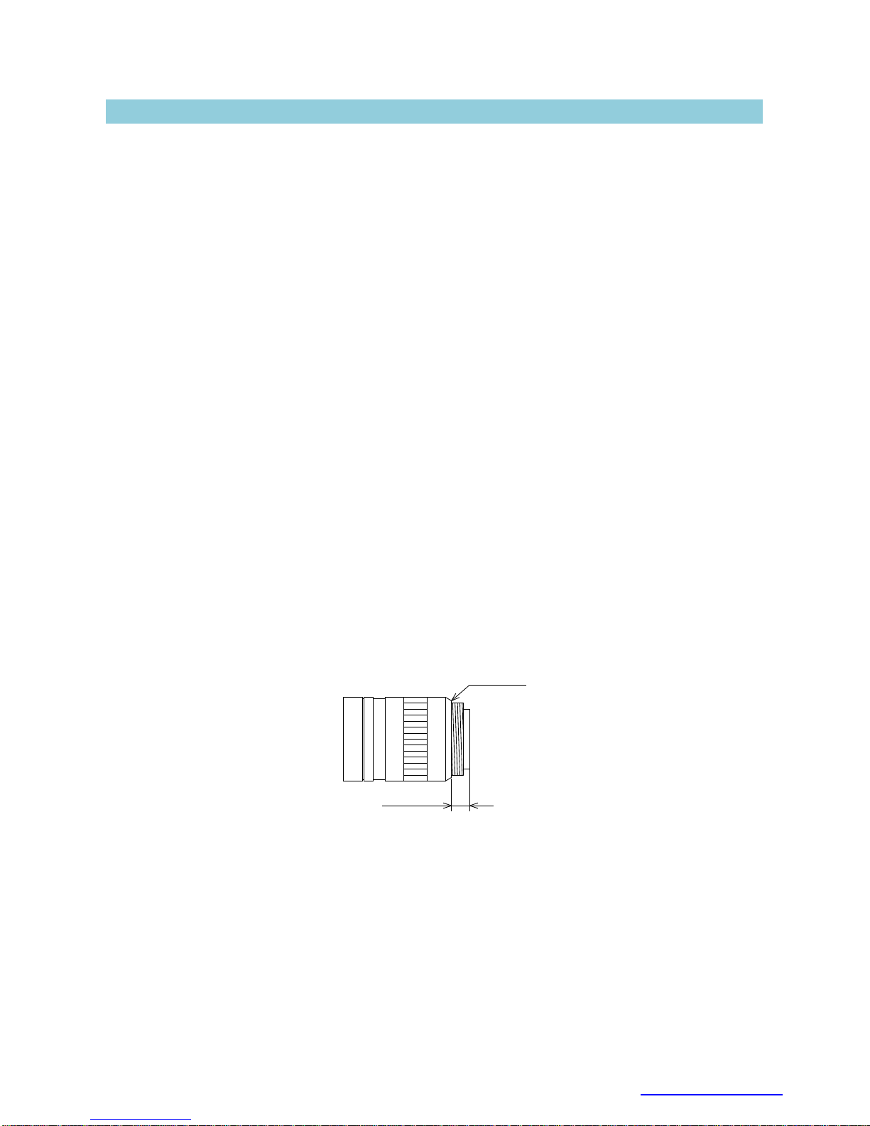
As for the C-mount lens used combining this product, the projection distance from bottom of the
screw should use 10mm or less.
10mm or less
C-mount lens
Bottom of
the screw
Mounting to a pedestal
When mounting this product to a pedestal, make sure carefully that the lens doesn't touch with the
pedestal.
Do not shoot under intense light
Avoid intense light such as spot lights on part of the screen because it may cause blooming or
smears. If intense light falls on the screen, vertical stripes may appear on the screen, but this is not a
malfunction.
Page 6
4
D4212818G
Copyright © 2013 TOSHIBA TELI CORPORATION, All rights reserved. www.toshiba-teli.co.jp
Occurrence of moiré
If you shoot thin stripe patterns, moiré patterns (interference fringes) may appear. This is not a
malfunction.
Occurrence of noise on the screen
If an intense magnetic or electromagnetic field is generated near the camera or connection cable,
noise may be generated on the screen. If this occurs, move the camera or the cable.
Handling of the protective cap
If the camera is not in use, attach the lens cap to the camera to protect the image pickup surface.
If the equipment is not to be used for a long duration
Turn off power to the camera for safety.
If the equipment is not to be used for along duration
Turn off power to the camera for safety and attach the lens cap to the camera to protect the image
pickup surface.
Maintenance
Turn off power to the equipment and wipe it with a dry cloth.
If it becomes severely contaminated, gently wipe the affected areas with a soft cloth dampened with
diluted neutral detergent. Never use alcohol, benzene, thinner, or other chemicals because such
chemicals may damage or discolor the paint and indications.
If the image pickup surface becomes dusty, contaminated, or scratched, consult your sales
representative.
Disposal
When disposing of the camera, it may be necessary to disassemble it into separate parts, in
accordance with the laws and regulations of your country and/or municipality concerning
environmental contamination.
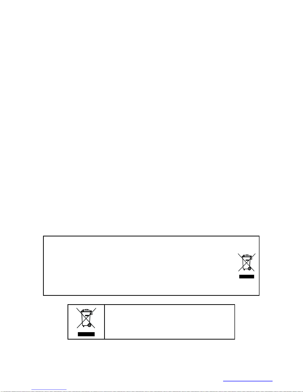
Following information is only for EU-member states:
The use of the symbol indicates that this product may not be treated as household
waste. By ensuring this product is disposed of correctly, you will help prevent
potential negative consequences for the environment and human health, which could
otherwise be caused by inappropriate waste handling of this product. For more
detailed information about the take-back and recycling of this product, please contact
your supplier where you purchased the product.
“This symbol is applicable for EU member states only”
Page 7

5
D4212818G
Copyright © 2013 TOSHIBA TELI CORPORATION, All rights reserved. www.toshiba-teli.co.jp
1. Overview
This BU series is an integrated-(one-body)-type camera that adopts all pixel data readout inter line
CCD. These are BU030 (VGA 1/3 type), BU031 (VGA 1/2 type), BU080 (XGA), BU130 (SXGA). Suffix
[C] or [CF] is attached to the color models. For video output and camera control, the USB 3.0 interface
standard is adopted for high transfer rate, and it is easy to integrate into industrial equipment.
2. Features
2.1 High frame rate
Supporting high frame rate, BU030 VGA 125fps, BU031 VGA 125fps, BU080 XGA 40fps, BU130
SXGA 30fps.
2.2 All pixel readout
All pixel signals (in the effective area) are output in one frame processing.
2.3 Full frame shutter
Since all pixels are output even in Random Trigger Shutter operation, high resolution can be
achieved, without deteriorating the vertical resolution.
2.4 Square grids
The CCD pixels arrayed in square grids facilitates computation for image processing.
2.5 USB* 3.0 interface
Video output and camera control are performed via the USB 3.0 standard interface. Data transfer
is up to 5Gbps (Maximum) that enables to output uncompressed video data at high frame rate.
2.6 USB3 Vision* conformity
This product is based on USB3 Vision Ver.1.0.
2.7 GenICam* Ver.2.3 conformity
This product is based on GenICam Generic Interface for Cameras Ver.2.3.
Page 8

6
D4212818G
Copyright © 2013 TOSHIBA TELI CORPORATION, All rights reserved. www.toshiba-teli.co.jp
2.8 IIDC2* Digital Camera Control Specification Ver.1.0.0 conformity
This product is based on IIDC2 Digital Camera Control Specification Ver.1.0.0.
2.9 e-CON* Connector adoption
The e-CON connector adoption enables to assemble the cable easily without using special tools.
2.10 Binning mode
B/W models have binning mode. In this mode, pixel data is combined by vertical and horizontal.
Vertical binning mode achieves high frame rate
2.11 Random Trigger Shutter
The Random Trigger Shutter function provides images in any timing by input of an external trigger
signal. Trigger control from PC is available as well.
2.12 Scalable
Selectable video output area. This mode achieves higher frame rate by reducing vertical output
area. And reduces occupied data rate of USB bus by reducing horizontal output area.
2.13 Color processing
Color models have built in color processing. There are RGB, YUV 4:2:2, YUV 4:1:1, Bayer and
Mono output modes.
2.14 IR-cut filter
Build-in IR-cut filter models are optional for color models.
Suffix [F] is attached to the model name of built-in IR-cut filter model. (e.g. BU030CF, BU130CF)
* Suffix [F] is not shown in the common part of specifications.
2.15 Compact and lightweight
This camera is compact and lightweight; it is easy to integrate into industrial equipment.
2.16 EU RoHS & Chinese ROHS
* USB is a unified standard established by USB-IF(USB Implementers Forum).
* USB3 Vision is a unified standard established by AIA (Automated Imaging Association).
* GenICam is a registered trademark of EMVA (European Machine Vision Association).
* IIDC2 is a unified standard established by JIIA (Japan Industrial Association).
* e-CON (Easy & Economy connector) is a sensor connector that is normalized by the
manufacturer of the sensor, FA equipment and connector.
Page 9

7
D4212818G
Copyright © 2013 TOSHIBA TELI CORPORATION, All rights reserved. www.toshiba-teli.co.jp
3. Configuration
(1) Camera body
* No application software and manuals are attached to this camera.
4. Optional part
- Camera mounting kit Model name: CPTBU
* Contact your dealer / distributor for details of option units.
Page 10

8
D4212818G
Copyright © 2013 TOSHIBA TELI CORPORATION, All rights reserved. www.toshiba-teli.co.jp
5. Functions
5.1 Gain
Manual gain control is available from 0 to +18dB.
Notes on gain setting:
Setting the gain value too high increases noises. When you adjust the brightness of the image, I ask you
to have final image quality checked with your environment.
5.2 Black Level
Black level is adjustable from -5% to +25% as white saturation level is 100%.
5.3 Gamma
Gamma correction curve is adjustable from 0.45 to 1.
5.4 LUT (Look Up Table)
Arbitrary curve and binarization are possible by using 10 bit input and 10 bit output LUT.
5.5 Exposure Time
Manual exposure time control is available. Exposure time is adjustable by the internal sync signal.
5.6 White balance
Color models have two white balance modes, manual white balance (MWB) and one-push auto white
balance (OPWB). Select the mode to suit the subject and purpose.
5.6.1 MWB
R/B gain can be set independently for each.
5.6.2 OPWB
When OPWB is used, the camera itself adjusts R/B gain to ensure the correct white balance for the
effective area.
5.7 Masking
Color models have RGB 3x3 matrixes correction.
Page 11
9
D4212818G
Copyright © 2013 TOSHIBA TELI CORPORATION, All rights reserved. www.toshiba-teli.co.jp
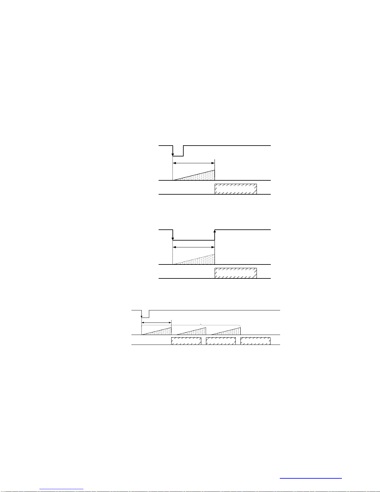
5.8 Random Trigger Shutter
An image is captured at the desired timing using trigger signal input. External trigger signal from
trigger input connector and software trigger from control command via the USB 3.0 interface are
available (Only in Edge mode). Trigger polarity is selectable (High active / Low active).
Note that Random Trigger Shutter will cause a delay between trigger signal and start of exposure.
See 7. Timing Chart for detail.
- Edge mode (TriggerSequence0)
The exposure time is determined by Exposure Time setting.
Image
USB bus
Exposure
Trigger
ExposureTime
- Level mode (TriggerSequence1)
The exposure time is determined by the pulse width of the trigger signal.
USB bus
Exposure
Trigger
Pulse Width
Image
- Bulk mode (TriggerSequence6)
Camera exposes and transfers multiple frames by a single trigger.
Image
USB bus
Exposure
Trigger
ExposureTime
Image Image
TriggerAdditionalParameter = 3
Page 12

10
D4212818G
Copyright © 2013 TOSHIBA TELI CORPORATION, All rights reserved. www.toshiba-teli.co.jp
Notes on long exposure:
- When you set the exposure time longer than approximately 1 second, white spots and the
unevenness in highlight portion might occasionally be observed on screen. This phenomenon is
due to the characteristics of the CCD device. It’s not a malfunction of the camera itself.
Note on Random Trigger Shutter:
- When the trigger signal is noisy, there is a possibility of causing the malfunction. In this case, please
input a noise-free signal.
5.9 Trigger Delay
You can add the delay between trigger signal input and the start of exposure.
USB bus
Exposure
Trigger signal
Image
TriggerDelay
Page 13

11
D4212818G
Copyright © 2013 TOSHIBA TELI CORPORATION, All rights reserved. www.toshiba-teli.co.jp
5.10 Event
Camera notifies FrameTrigger status and other information by USB3 Vision Event Packet.
- FrameTrigger : Reception of Frame Start Trigger
- FrameTriggerError : Rejection of Frame Start Trigger
- FrameTriggerWait : Start of waiting for Frame Start Trigger
- FrameTransferStart : Start of transferring streaming data
- FrameTransferEnd : End of transferring streaming data
- ExposureStart : Start of Exposure
- ExposureEnd : End of Exposure
- Timer0Start : Start of Timer0
- Timer0End : End of Timer0
Events timing are as following chart.
A B C D E
A B C
Overlap Trigger Reception
A B C
(1)
(6) (7) (6) (7) (6) (7)
(1) (1)
(4) (5) (4) (5) (4) (5)
(3) (3) (3)
FrameTriggerWait will be activated before
approx. (Sensor Read Out End - Exposure Time)
D E
D E
(6) (7)
(1)
(4) (5) (4)
(3)
(2) (1)
(6) (7)
This trigger is
ignored.
Overlap Trigger Rejection
Event Name
FrameTriggerWait
(Low Active)
EXT_TRIG
(Falling edge)
Exposure
Sensor Read Out
Bus Transfer
Timer0Active
(Low Active)
(8) (9) (8) (9) (8) (9) (8) (9) (8) (9)
(3) FrameTriggerWait
(4) FrameTransferStart
(5) FrameTransferEnd
(6) ExposureStart
(7) ExposureEnd
(1) FrameTrigger
(2) FrameTriggerError
(8) Timer0Start
(9) Timer0End
: Reception of Frame Start Trigger.
: Rejection of Frame Start Trigger.
: Start of waiting for Frame Start Trigger.
: Start of transferring streaming data.
: End of transferring streaming data.
: Start of Exposure.
: End of Exposure.
: Start of Timer0.
: End of Timer0.
Page 14

12
D4212818G
Copyright © 2013 TOSHIBA TELI CORPORATION, All rights reserved. www.toshiba-teli.co.jp
5.11 GPIO
Selected signals are output from GPIO pins of I/O connector. Following signals are selectable.
Output signal is 5V CMOS.
TIMER0 ACTIVE : This signal can be used as strobe control signal.
The delay time and pulse width of this signal are configurable.
USER OUTPUT : Level selectable user output by register setting.
EXPOSURE ACTIVE : Period from exposure start to end.
FRAME ACTIVE : Period from exposure start to CCD transfer completion.
FRAME TRANSFER : Period of transferring image data on USB bus.
FRAME TRIGGER WAIT : Indicating waiting a Random Trigger Shutter.
An External trigger is input during this period,
exposure starts immediately.
EXT_TRIG
Exposure
VD
CCD Transfer
USB Bus
TIMER0 ACTIVE
EXPOSURE
ACTIVE
FRAME ACTIVE
FRAME
TRANSFER
FRAME TRIGGER
WAIT
Delay Duration
* ActiveLow
Page 15

13
D4212818G
Copyright © 2013 TOSHIBA TELI CORPORATION, All rights reserved. www.toshiba-teli.co.jp
5.12 Scalable mode
Scalable mode is to read out arbitrary area of the image. Only single rectangle is selectable.
Concave or convex shape is impossible. The number of selectable window is only one.
- Window size: {A+2*m (H)} * {B+2*n (V)}
A, B = minimum unit size
m, n = integer
The window size is equal or less than maximum image size.
- Start address: {2*i (H)} * {2*j (V)}
i, j = integer
The window size is equal or less than maximum image size.
BU030
BU031
BU080
BU130
Width and OffsetX unit size
2×2
2×2
2×2
2×2
Height and OffsetY unit size
2×2
2×2
2×2
2×2
Minimum unit size (H) * (V)
160×120
160×120
256×192
160×120
Maximum unit size (H) * (V)
640×480
640×480
1024×768
1280×960
BU030C
BU130C
Width and OffsetX unit size
2×2
2×2
Height and OffsetY unit size
2×2
2×2
Minimum unit size (H) * (V)
160×120
160×120
Maximum unit size (H) * (V)
640×480
1280×960
( X , Y )=( 2 * i , 2 * j )
A + 2 * m
B + 2 * n
In the scalable mode, camera reads out only necessary area at the normal speed and reads out other
area at high speed. The trigger interval can be shorter when the vertical height size is small. However,
the trigger interval cannot be shorter when the horizontal width size is small, due to the operation
mechanism of the CCD sensor.
Notes on scalable mode:
- White lines may occur in the upper portions of the screen when strong light exists in a wide area
durring the scalable mode. This is not a malfunction. If white lines occur, adjust the amount of
incident light using the lens.
Page 16

14
D4212818G
Copyright © 2013 TOSHIBA TELI CORPORATION, All rights reserved. www.toshiba-teli.co.jp
5.13 Binning Mode
B/W models have binning mode. In the binning mode, pixel data is combined by vertical and
horizontal.
BU030
BU031
BU080
BU130
Binning mode
2(H)*2(V)
2(H)*2(V)
2(H)*2(V)
2(H)*2(V)
5.14 User Free Memory
A free memory area is available to read and write arbitrary data for user. Individual numbers can be
assigned when multiple BU cameras are connected.
5.15 Test Pattern
Following test patterns are available.
Black : Full screen 0 LSB (@ 8-bit)
White : All pixels 255 LSB (@ 8-bit)
Gray A : Full screen 170 LSB (10101010B) (@ 8-bit)
Gray B : Full screen 85 LSB (01010101B) (@ 8-bit)
Horizontal ramp waveform
Vertical ramp waveform
Page 17

15
D4212818G
Copyright © 2013 TOSHIBA TELI CORPORATION, All rights reserved. www.toshiba-teli.co.jp
6. Specifications
6.1 Electrical specification
Model Name
BU030
BU031
BU080
BU130
Imager
all-pixel-data-readout interline transfer CCD
Number of total pixels
(H) * (V)
692*504
692*504
1077*788
1348*976
Number of effective pixels
(H) * (V)
659*494
659*494
1034*779
1296*966
Number of Video out pixels
(H) * (V)
640*480
640*480
1024*768
1280*960
Scanning area
(H) * (V) [mm]
4.88*3.66
(1/3 type)
6.52*4.89
(1/2 type)
4.81*3.62
(1/3 type)
4.86*3.62
(1/3 type)
Pixel size (H) * (V) [μm]
7.4 *7.4
9.9 *9.9
4.65 *4.65
3.75 *3.75
Scan method
Non-interlace
Aspect ratio
4:3
Standard sensitivity
1700lx
F5.6, 1/125s
1700lx
F5.6, 1/125s
1700lx
F5.6, 1/40s
1300lx
F8, 1/30s
Minimum sensitivity
F1.4, Gain +18dB, Video level 50%
7lx
7lx
7lx
3lx
Gain
MANUAL
Setting range
0 to +18dB (factory setting : 0dB)
Black Level
-5 to 25% (factory setting : 0% [ 0LSB@8bit ])
Gamma
γ=1.0 to 0.45 (factory setting : γ=1.0)
LUT
Input 10 bit, Output 10 bit
User Setting Memory
15 channels
User Free Memory
64 Byte
Test Pattern
Black, White, Gray A, Gray B
Horizontal ramp waveform, Vertical ramp waveform
(factory setting : OFF)
Power supply
DC +5V5% (from USB connector)
Power consumption(*1)
2.6W (maximum)
Page 18

16
D4212818G
Copyright © 2013 TOSHIBA TELI CORPORATION, All rights reserved. www.toshiba-teli.co.jp
Model Name
Without IR-cut filter
BU030C
BU130C
With IR-cut filter
BU030CF
BU130CF
Imager
all-pixel-data-readout interline transfer CCD
Number of total pixels
(H) * (V)
692 * 504
1348 * 976
Number of effective pixels
(H) * (V)
659 * 494
1296 * 966
Number of Video out pixels
(H) * (V)
640 * 480
1280 * 960
Scanning area
(H) * (V) [mm]
4.88 * 3.66
(1/3 type)
4.86 * 3.62
(1/3 type)
Pixel size (H) * (V) [μm]
7.4 * 7.4
3.75 * 3.75
Color filter
RGB primary color mosaic-on-tip color filter
Scan method
Non-interlace
Aspect ratio
4:3
Standard sensitivity
(*2)
3500lx
F5.6, 1/125s
1250lx
F5.6, 1/30s
Minimum sensitivity
F1.4, Gain +18dB, Video level 50%
14lx
5lx
Gain
MANUAL
Setting range
0 to +18dB (factory setting : 0dB)
Black Level
-5 to 25% (factory setting : 0% [ 0LSB@8bit ])
White balance
MWB, OPWB (factory setting : MWB)
Effective range
Without IR-cut filter : 3,500~6,500K
With IR-cut filter : 2,500~6,500K
MWB setting format
R/B gain independent setting
OPWB effective area
Full (Full pixel)
Color Correction Matrix
3 x 3 matrix
Gamma
γ=1.0 to 0.45 (factory setting : γ=1.0)
LUT
Input 10 bit, Output 10 bit
User Setting Memory
15 channels
User Free Memory
64 Byte
Test Pattern
Black, White, Gray A, Gray B
Horizontal ramp waveform, Vertical ramp waveform
(factory setting : OFF)
Power supply
DC +5V5% (from USB connector)
Power consumption(*1)
2.7W (maximum)
(*1) at the all pixel readout
(*2) with IR-cut filter
Page 19

17
D4212818G
Copyright © 2013 TOSHIBA TELI CORPORATION, All rights reserved. www.toshiba-teli.co.jp
6.2 Internal sync signal specification
BU030
BU031
BU080
BU130
Fundamental clock
frequency
50.000MHz
±100ppm
50.000MHz
±100ppm
45.000MHz
±100ppm
50.000MHz
±100ppm
BU030C
BU130C
Fundamental clock
frequency
50.000MHz
±100ppm
50.000MHz
±100ppm
6.3 Electronic shutter specification
BU030
BU031
BU080
BU130
Exposure time
MANUAL
MANUAL
10μs to 16s
10μs to 16s
30μs to 16s
30μs to 16s
BU030C
BU130C
Exposure time
MANUAL
MANUAL
10μs to 16s
30μs to 16s
6.4 Random Trigger Shutter specification
Trigger Mode
External trigger, Software trigger
(factory setting : External trigger)
External trigger
Input via I/O connector
Input circuit
Inside
DC3.3V
0V
10kΩ
Input level
Low: 0 to 0.5V, High: 2.0 to 24.0V
Polarity
High active / Low active (factory setting : Low active)
Pulse width
50μs (minimum)
Input impedance
High impedance
Software trigger
USB3 Vision command control
Exposure time
Edge mode, Level mode (factory setting : Edge mode)
Edge mode
The exposure time depends on the MANUAL Exposure time setting
Level mode The exposure time depends on External trigger width
Bulk mode
The exposure time depends on the MANUAL Exposure time setting
Max number of Exposures
in Bulk mode
255 times
Trigger Delay
0 to 2000000μs (factory setting : 0μs)
Page 20

18
D4212818G
Copyright © 2013 TOSHIBA TELI CORPORATION, All rights reserved. www.toshiba-teli.co.jp
6.5 GPIO Output signal specification
Output channel
2 channel
Output signal
TIMER0 ACTIVE, USER OUTPUT, EXPOSURE ACTIVE,
FRAME ACTIVE, FRAME TRANSFER, FRAME TRIGGER WAIT
Output level
5V CMOS
Maximum Current
+/-32mA
Polarity
High active / Low active (factory setting : Low active)
Timer0 Active
Delay
0 to 2000000μs (factory setting : 0μs)
Duration
0 to 2000000μs (factory setting : 0μs)
TimerTriggerSource Line0Active, ExposureStart, FrameTrigger
6.6 Interface specification
Interface
USB 3.0 (Only SuperSpeed is supported)
Transmission speed
5Gbps (Maximum)
Protocol
USB3 Vision
Cable length
Up to 3.0 m
Page 21

19
D4212818G
Copyright © 2013 TOSHIBA TELI CORPORATION, All rights reserved. www.toshiba-teli.co.jp
6.7 LED states
Camera state
Lamp indication
No power
Off
Link detection in progress
Fast flash green (ON:20ms, OFF:60ms)
Connection Error
Flash alternate red / green
SuperSpeed connected, but no data being transferred
Flash green (ON: 200ms, OFF: 800ms)
SuperSpeed connected, waiting for trigger
Flash orange (ON: 200ms, OFF: 800ms)
Data being transferred
Solid Green
Error during data transfer
Solid Red (Time period: 500ms)
Stand-by
Super slow flash orange (ON:200ms, OFF: 2800ms)
6.8 Image output format
BU030
BU031
BU080
BU130
Image output format
Mono 8 bit
Mono 10bit
Frame rate
(at the all pixel readout)
Maximum
125 fps
Maximum
125 fps
Maximum
40 fps
Maximum
30 fps
BU030C
BU130C
Image output format
YUV4:1:1 12bit
YUV4:2:2 16bit
RGB 24bit
Bayer 8bit
Bayer 10bit
Mono 8bit
Frame rate
(at the all pixel readout)
Maximum
125 fps
Maximum
30 fps
Notes on Dropping Frames:
- Depends on your PC or USB interface card configurations, images may not be captured normally
(e.g. dropping frames may occur). In this case, change to frame rate setting lower.
6.9 Event notification
Event name
FrameTrigger, FrameTriggerError, FrameTriggerWait
FrameTransferStart, FrameTransferEnd
ExposureStart, ExposureEnd
Timer0Start, Timer0End
Event notification delay
approx. 10us later from the event occurs
Time stamp unit
16.7ns (60.0MHz)
Page 22

20
D4212818G
Copyright © 2013 TOSHIBA TELI CORPORATION, All rights reserved. www.toshiba-teli.co.jp
6.10 Machine external specification
Dimensions
29 mm(W) * 29 mm (H) * 13 mm (D) (Not including protrusion)
Mass
approx. 27g
Lens mount
C-mount
Flange back
17.526mm
Camera body grounding
insulation status
Non-Conductive between circuit GND and camera body
6.11 Operation Ambient conditions
Operation assurance
Temperature: 0°C to +40 °C, Camera housing temperature: less than 50 °C
Humidity: 10% to 90% (no condensation)
Storage assurance
Temperature : -20 to +60 Celsius
Humidity : +90% or less (no condensation)
EMC condition
EMI (Electro-Magnetic interference) : EN61000-6-4,
FCC Part 15 Subpart B Class A
EMS (Electro-Magnetic susceptibility) : EN61000-6-2
Notes on Heat Dissipation:
- The temperature of camera housing must be kept less than 50 Celsius.
Please provide sufficient heat dissipation depending on your installation.
Page 23

21
D4212818G
Copyright © 2013 TOSHIBA TELI CORPORATION, All rights reserved. www.toshiba-teli.co.jp
Notes on Conformity of the EMC:
The adaptability of the safety standard of this camera is assured in the condition of combination with the following parts:
- USB Cable USB3C-A/1-CS/1-C-0 (COMOSS Electronic Co., Ltd.)
- e-CON Cable 3.0m, Shield cable (Fabricated parts)
Parts:
- e-CON connector XN2A-1470 (OMRON Corporation)
- Shielded wire UL1533 (AWG28) (Hitachi Cable, Ltd.)
Connection:
e-CON
1
2
3
4
BNC
GPIO(Line2)
GPIO(Line1)
GND
TRIG IN
GPIO(Line2)
GPIO(Line1)
TRIG IN
BNC
Please confirm the EMC adaptability when it combines with parts other than them.
Page 24

22
D4212818G
Copyright © 2013 TOSHIBA TELI CORPORATION, All rights reserved. www.toshiba-teli.co.jp
6.12 Connector pin assignment
USB 3.0 interface connector
Connector model: WMUR-10F6L1PH5N
(WIN WIN PRECISION INDUSTRIAL)
Pin No.
I/O
Signal Name
Function
1 -
VBUS
Power
2 I/O
D-
USB2.0 differential pair
3 I/O
D+
4 -
NC
Not connected
5 -
GND
Ground for power return
6 O
SSTX-
SuperSpeed transmitter differential pair
7 O
SSTX+
8 -
GND_DRAN
Ground for SuperSpeed signal return
9 I
SSRX-
SuperSpeed receiver differential pair
10 I SSRX+
I/O Connector
Connector (Camera side) 37204-62B3-004PL (Sumitomo 3M)
or equivalent
Matching connector (Cable side) Connectors which conformed to e-CON
e.g. 37104 series (Sumitomo 3M),
RITS 4P series (Tyco)
* Matching connector is not an accessory of this product.
Pin assignment
↑TOP
* Above figure is connector view from insert side.
Pin No.
I/O
Signal Name
Function
1 O
GPIO(Line2)
GPIO Output (*1)
2 O
GPIO(Line1)
GPIO Output
3 -
GND
Ground
4 I
TRIG_IN
Trigger Input
(*1) Contact your sales representative about availability of this function.
1
2
3
4
Page 25

23
D4212818G
Copyright © 2013 TOSHIBA TELI CORPORATION, All rights reserved. www.toshiba-teli.co.jp
6.13 Typical spectral response
The lens characteristics and light source characteristics is not reflected in table.
<BU030>
400 500 600 700 800 1000900
Wave Length [nm]
0
0.1
0.2
0.3
0.4
0.5
0.6
0.7
0.8
0.9
1.0
Relative Response
<BU031>
400 500 600 700 800 1000900
Wave Length [nm]
0
0.1
0.2
0.3
0.4
0.5
0.6
0.7
0.8
0.9
1.0
Relative Response
Page 26

24
D4212818G
Copyright © 2013 TOSHIBA TELI CORPORATION, All rights reserved. www.toshiba-teli.co.jp
<BU080>
400 500 600 700 800 1000900
Wave Length [nm]
0
0.2
0.4
0.6
0.8
1.0
Relative Response
<BU130>
400 500 600 700 800 1000900
Wave Length [nm]
0
0.2
0.4
0.6
0.8
1.0
Relative Response
Page 27

25
D4212818G
Copyright © 2013 TOSHIBA TELI CORPORATION, All rights reserved. www.toshiba-teli.co.jp
<BU030C>
400 450 500 550 600 700650
Wave Length [nm]
0
0.2
0.4
0.6
0.8
1.0
Relative Response
B
G
R
<BU030CF>
400 450 500 550 600 700650
Wave Length [nm]
0
0.2
0.4
0.6
0.8
1.0
Relative Response
B
G
R
Page 28

26
D4212818G
Copyright © 2013 TOSHIBA TELI CORPORATION, All rights reserved. www.toshiba-teli.co.jp
<BU130C>
400 450 500 550 600 700650
Wave Length [nm]
0
0.2
0.4
0.6
0.8
1.0
Relative Response
B
G
R
<BU130CF>
400 450 500 550 600 700650
Wave Length [nm]
0
0.2
0.4
0.6
0.8
1.0
Relative Response
B
G
R
Page 29

27
D4212818G
Copyright © 2013 TOSHIBA TELI CORPORATION, All rights reserved. www.toshiba-teli.co.jp
7. Timing chart
Image data outputs are transferred with USB bulk transfer. Timing numerical value below is
described by absolute prerequisite that camera can use transmission band without restriction of other
device. When there is other device on the same bus, the value described below is not guaranteed.
7.1 In Normal shutter mode
Pixel format: Mono 8, all pixels readout
T2
T1
USB bus
Exposure
Image Image
Model Name
T1 [ms]
T2 [ms]
Default Frame Rate
[ms]
BU030
7.8
Frame Rate
setting by the
application.
8.0
BU031
7.8
8.0
BU080
25.0
25.0
BU130
33.3
33.3
BU030C
7.8
8.0
BU130
33.3
33.3
* If the value of T2 is not set by the application, it will be the same as T1.
Page 30

28
D4212818G
Copyright © 2013 TOSHIBA TELI CORPORATION, All rights reserved. www.toshiba-teli.co.jp
7.2 In Random Trigger Shutter mode
- Edge mode / Bulk mode
Pixel format: Mono 8, all pixel readout
Image
USB bus
Exposure
TRIG_IN
T3
T1
- Level mode
Pixel format: Mono 8, all pixel readout
Image
USB bus
Exposure
TRIG_IN
T3
T1
T4
Model Name
T3 [μs]
T4 [μs]
BU030
1.0
2.5
BU031
1.0
2.5
BU080
2.2
34.0
BU130
1.2
7.1
BU030C
1.0
2.5
BU130C
1.2
7.1
* The value of T1 and T2 are the same as the value of normal shutter mode.
* T3 and T4 are typical value.
Notes of Random Trigger Shutter mode:
- In the period when FRAME_TRIGGER_WAIT (refer to GPIO output signals) signal is inactive,
user must not input external trigger signal to this camera.
- When the interval of the input trigger signal is extremely short, or when the trigger signal is
noisy, there is a possibility of causing the malfunction. In this case, please input a proper trigger
signal.
Page 31

29
D4212818G
Copyright © 2013 TOSHIBA TELI CORPORATION, All rights reserved. www.toshiba-teli.co.jp
8. Warranty rules
8.1 Warranty term
Warranty term is 36 months after your purchase. We may assume the date of the purchase from our
shipping date when the date is unidentified.
8.2 Limited Warranty
Free warranty is not applicable for the troubles, damages or losses caused by the cases of the
followings, even if it is during the warranty term.
1. Natural exhaust, wear or degradation of a component parts
2. Handling against the instructions and conditions described in the instruction manual
3. Remodeling, adjustment and the part exchange. (including the opening of the enclosure box
and the alteration)
4. Using the accessories not included with the product or our non-designated optional articles
5. Damages caused during the transportation or deficiency of the handling such as drop or fall of
the products after the products having been transferred to customers, leaving the products to
corrosive environment such as sunlight, fire, sand, soil, heat, moisture, or an inappropriate
storing method
6. A fire, an earthquake, a flood, a lightning, or other natural disasters, pollution and a short circuit,
abnormal voltage, excessive physical pressure, theft, other accident
7. When connected to a product which is not recommended
8. When connected to the power supply which is not suitable
9. Forgery product, products which does not have proper serial number, products of which serial
number is forged, damaged or deleted
10. All defects that happened after the expiration for a warranty term
Page 32

30
D4212818G
Copyright © 2013 TOSHIBA TELI CORPORATION, All rights reserved. www.toshiba-teli.co.jp
9. Repair
9.1 Repair Methods
Exchange to a replacement or an equal function product.
9.2 Repair request methods
On the occasion of a repair request, please return the defective product with the failure situation
report sheet to be filled out.
Please read the following instructions carefully.
1. Please return our product alone, taking out of your equipment in case that our product is
installed to an equipment
2. We are unable to return the information such as your own serial numbers, control number, the
identification seal, if it is attached to the returned products. Please keep record before you
return the product.
3. As the data saved in the camera will not be kept after the repair, please take out data before
return.
4. We are unable to accept the cancellation after the repair request by the customer's reason.
5. About the repair product shipping expenses, please bear the charges when you return the
product to us. We bear the charges to you from us only for a warranty period.
6. We are unable to accept your request of a delivery date and time of the product return, or the
delivery method.
7. We are unable to accept a trouble factor investigation, the request of the repair report.
8. We accept a repair of out of warranty product, if it is reparable.
9. The proprietary rights of the repair request products after the exchange repair belong to us.
10. The immunity from responsibility of the product is applied in the repair completion products.
* Please refer for the inquiry about the software to our homepage or sales personnel.
Page 33

31
D4212818G
Copyright © 2013 TOSHIBA TELI CORPORATION, All rights reserved. www.toshiba-teli.co.jp
10. Outline Drawing
Page 34

32
D4212818G
Copyright © 2013 TOSHIBA TELI CORPORATION, All rights reserved. www.toshiba-teli.co.jp
In order to grasp the details of failure,
please fill out the following information, and send us the defective product with this report sheet enclosed.
(1) Customer information
Company Name
Department Your Name
Telephone number E-Mail address FAX number
Postal code number Address
(3) We suggest a possible solution before your repair request.
Please ensure your safety when you check following items.
Please handle power supply with proper procedure, and make sure it does not impede any operation.
a) Restart the power supply of this product.
Check →
□ Tried □ Not Tried
Please turn off th is produc t on ce, switch on a power supply again after passing for a while, and confir m operation.
b) Exchange for other products.
Check →
□ Tried □ Not Tried
Please e xchange for oth er same produc ts, and confirm operation.
c) Connect to other PC systems.
Check →
□ Tried □ Not Tried
Please c onn ect this product to othe r PCs, and confirm operation.
d) Check Specifications of this product.
Check →
□ Tried □ Not Tried
Please c onfirm that specifications of this product conform to u sage en viron men t refering to following URL.
URL:http://www.toshiba-teli.co.jp/index.htm Please c hec k our website fo r th e latest in formation.
(4) Failure situation
Model name
Serial No.
Your dealer
Purchase date
Failure condition:
(5) From when
□ Unknown □
From the beginning
□ After a while
□ After environment was changed.
( □ Others )
(6) Occurrence frequency
□ Unknown □ It certainly occurs. □ It sometimes occurs.
□ It occurs, after time passes.
( □ Others )
Reception date : Receipt No. : JOB No. : Check :
(Please fill out the phenomenon in detail.)
The offered personal information is not used for any purposes other than after-sale service, such as repair of a product and an
inquiry, and the questionnaire of the improvement in customer satisfaction.
Moreover, except for the case where it commissions within limits required for the above-mentioned purpose achievement, it does not
indicate to a third party without a visitor's consent.
We pay careful attention and manage a visitor's information.
Failure situation report sheet
<For dealer use>
■Entry date
(2) Return address
Please fill out this information, if the return addrrss is different from above address (1).
Ver.2.06
■Accurual date
 Loading...