

Page 1

Toshiba Personal Computer
PORTEGE Z830 Satellite Z830
Maintenance Manual
First edition October 2011
TOSHIBA CORPORATION
File Number 960-883
[CONFIDENTIAL]
Page 2

Copyright
© 2011 by Toshiba Corporation. All rights reserved. Under the copyright laws, this manual
cannot be reproduced in any form without the prior written permission of Toshiba. No patent
liability is assumed with respect to the use of the information contained herein.
Toshiba Personal Computes satellite PORTEGE Z830 Satellite Z830
Series Maintenance
Manual
First edition October 2011
Disclaimer
The information presented in this manual has been reviewed and validated for accuracy. The
included set of instructions and descriptions are accurate for the
at the time of this manual's production. However, succeeding computers and manuals
Series
PORTEGE Z830 Satellite Z830
are subject to change without notice. Therefore, Toshiba assumes no liability for damages
incurred directly or indirectly from errors, omissions, or discrepancies between any
succeeding product and this manual.
Trademarks
IBM is a registered trademark and IBM PC is a trademark of International Business
Machines Corporation.
Intel, Intel SpeedStep, Intel Core, Celeron and Centrino are trademarks or registered
trademarks of Intel Corporation.
Windows, Microsoft and Windows Vista are either registered trademarks or trademarks of
Microsoft Corporation.
Bluetooth is a trademark owned by its proprietor and used by TOSHIBA under license.
InterVideo and WinDVD are registered trademarks of InterVideo Inc.
Photo CD is a trademark of Eastman Kodak.
i.LINK is trademark and registered trademark of Sony Corporation.
Other trademarks and registered trademarks not listed above may be used in this manual.
ii PORTEGE Z830 Satellite Z830 Series Maintenance Manual (960-883) [CONFIDENTIAL]
Page 3

Preface
This maintenance manual describes how to perform hardware service maintenance for the
Toshiba Personal Computer satellite PORTEGE Z830 Satellite Z830 Series Maintenance
Manual (960-883) Series
The procedures described in this manual are intended to help service technicians isolate
faulty Field Replaceable Units (FRUs) and replace them in the field.
SAFETY PRECAUTIONS
Four types of messages are used in this manual to bring important information to your
attention. Each of these messages will be italicized and identified as shown below.
DANGER: “Danger” indicates the existence of a hazard that could result in death or
serious bodily injury, if the safety instruction is not observed.
WARNING: “Warning” indicates the existence of a hazard that could result in bodily
injury, if the safety instruction is not observed.
CAUTION: “Caution” indicates the existence of a hazard that could result in property
damage, if the safety instruction is not observed.
NOTE: “Note” contains general information that relates to your safe maintenance
service.
Improper repair of the computer may result in safety hazards. Toshiba requires service
technicians and authorized dealers or service providers to ensure the following safety
precautions are adhered to strictly.
Be sure to fasten screws securely with the right screwdriver. If a screw is not fully
fastened, it could come loose, creating a danger of a short circuit, which could cause
overheating, smoke or fire.
If you replace the battery pack or RTC battery, be sure to use only the same model
battery or an equivalent battery recommended by Toshiba. Installation of the wrong
battery can cause the battery to explode.
PORTEGE Z830 Satellite Z830 Series Maintenance Manual (960-883) [CONFIDENTIAL] iii
Page 4

The manual is divided into the following parts:
Chapter 1 Hardware Overview describes the Qosmio F60 Series system unit and
each FRU.
Chapter 2 Troubleshooting Procedures explains how to diagnose and resolve
FRU problems.
Chapter 3 Test and Diagnostics describes how to perform test and diagnostic
operations for maintenance servic e.
Chapter 4 Replacement Procedures describes the removal and replacement of the
FRUs.
Appendices The appendices describe the following:
Handling the LCD module
Board layout
Pin assignments
Keyboard scan/character codes
Key layout
Wiring diagrams
BIOS rewrite procedures
EC/KBC rewrite procedures
Reliability
iv PORTEGE Z830 Satellite Z830 Series Maintenance Manual (960-883) [CONFIDENTIAL]
Page 5

Conventions
This manual uses the following formats to describe, identify, and highlight terms and
operating procedures.
Acronyms
On the first appearance and whenever necessary for clarification acronyms are enclosed in
parentheses following their definition. For example:
Read Only Memory (ROM)
Keys
Keys are used in the text to describe many operations. The key top symbol as it appears on
the keyboard is printed in boldface type.
Key operation
Some operations require you to simultaneously use two or more keys. We identify such
operations by the key top symbols separated by a plus (+) sign. For example, Ctrl + Pause
(Break) means you must hold down Ctrl and at the same t i me press Pause (Break). If
three keys are used, hold down the first two and at the same time press the third.
User input
Text that you are instructed to type in is shown in the boldface type below:
DISKCOPY A: B:
The display
Text generated by the computer that appears on its display is presented in the type face
below:
Format complete
System transferred
PORTEGE Z830 Satellite Z830 Series Maintenance Manual (960-883) [CONFIDENTIAL] v
Page 6

Table of Contents
Chapter 1 Hardware Overview
1.1 Features ......................................................................................................................... 5
1.2 System Unit Block Diagram ....................................................................................... 11
1.3 3.5-inch Floppy Disk Drive (USB External) ............ ..... ..... ... ..... ...... .. ...... ..... ... ..... ..... 16
1.4 mSATA SSD ............................................................................................................... 17
1.5 Keyboard ..................................................................................................................... 18
1.6 TFT Color Display ................. ..................................................................................... 19
1.6.1 LCD Module ............................................................................................................... 19
1.7 Power Supply .............................................................................................................. 20
1.8 Batteries ...................................................................................................................... 22
1.8.1 Main Battery ............................................................................................................... 22
1.8.2 Battery Charging Control ............................................................................................ 23
1.8.3 RTC battery ................................................................................................................. 24
1.9 AC Adapter ................................................................................................................. 25
vi PORTEGE Z830 Satellite Z830 Series Maintenance Manual (960-883) [CONFIDENTIAL]
Page 7

Chapter 2 Troubleshooting Procedures
2.1 Troubleshooting ......................................................................................................... 2-6
2.2 Troubleshooting Flowchart ........................................................................................ 2-8
2.3 Power Supply Troubleshooting................................................................................ 2-13
2.3.1 Procedure 1 Power Status Check ............................................................................. 2-13
2.3.2 Procedure 2 Error Code Check ................................................................................ 2-15
2.3.3 Procedure 3 Connection Check ................................................................................ 2-20
2.3.4 Procedure 4 Charging Check ................................................................................... 2-21
2.3.5 Procedure 5 Replacement Check ............................................................................. 2-21
2.4 System Board Troubleshooting ................................................................................ 2-22
2.4.1 Procedure 1 Message Check .................................................................................... 2-23
2.4.2 Procedure 2 Debugging Port Check ......................................................................... 2-25
2.4.3 Procedure 3 Diagnostic Test Program Execution Check ......................................... 2-31
2.4.4 Procedure 4 Replacement Check ............................................................................. 2-31
2.5 USB FDD Troubleshooting ..................................................................................... 2-32
2.5.1 Procedure 1 FDD Head Cleaning Check ................................................................. 2-32
2.5.2 Procedure 2 Diagnostic Test Program Execution Check ......................................... 2-33
2.5.3 Procedure 3 Connector Check and Replacement Check ........................... .. ............. 2-34
2.6 mSATA SSD Troubleshooting ................................................................................ 2-36
2.6.1 Procedure 1 Partition Check (Not Used) ................................................................. 2-36
2.6.2 Procedure 2 Message Check .................................................................................... 2-37
2.6.3 Procedure 3 Format Check (Not Used) .................................................................... 2-38
2.6.4 Procedure 4 Diagnostic Test Program Execution Check ......................................... 2-39
2.6.5 Procedure 5 Connector Check and Replacement Check ........................... .. ............. 2-40
2.7 Keyboard Troubleshooting ...................................................................................... 2-41
2.7.1 Procedure 1 Diagnostic Test Program (and Windows)Execution Check ........... 2-41
2.7.2 Procedure 2 Connector Check and Replacement Check ........................... .. ............. 2-41
2.8 Touch pad Troubleshooting ..................................................................................... 2-43
2.8.1 Procedure 1 Diagnostic Test Program Execution Check ......................................... 2-43
2.8.2 Procedure 2 Connector Check and Replacement Check ........................... .. ............. 2-43
2.9 Display Troubleshooting .......................................................................................... 2-45
PORTEGE Z830 Satellite Z830 Series Maintenance Manual (960-883) [CONFIDENTIAL] vii
Page 8

2.10 LAN Troubleshooting .............................................................................................. 2-47
2.10.1 Procedure 1 Diagnostic Test Program Execution Check ......................................... 2-47
2.10.2 Procedure 2 Connector Check and Replacement Check ............................. ............. 2-47
2.11 Wireless LAN or Wireless LAN +Bluetooth Troubleshooting ............................. .. 2-49
2.11.1 Procedure 1 Transmitting-Receiving Check ........................................................... 2-49
2.11.2 Procedure 2 Antennas' Connection Check .............................................................. 2-49
2.11.3 Procedure 3 Replacement Check ............................................................................ 2-50
2.12 Sound Troubleshooting ............................................................................................ 2-51
2.12.1 Procedure 1 Diagnostic Test Program Execution Check ......................................... 2-51
2.12.2 Procedure 2 Connector Check ................................................................................. 2-51
2.12.3 Procedure 3 Replacement Check ............................................................................. 2-52
2.13 SD Card Slot Troubleshooting ................................................................................. 2-53
2.13.1 Procedure 1 Check on Windows OS ........................................................................ 2-53
2.13.2 Procedure 2 Connector Check and Replacement Check ............................. ............. 2-53
2.14 Fingerprint sensor Troubleshooting ......................................................................... 2-54
2.15 Web camera Troubleshooting .................................................................................. 2-59
2.15.1 Procedure 1 Check on Windows OS ........................................................................ 2-59
2.15.2 Procedure 2 Connector Check and Replacement Check ............................. ............. 2-59
2.16 3G Troubleshooting ................................................................................................. 2-61
2.17 HDMI Troubleshooting ........................................................................................... 2-63
2.17.1 Procedure 1 Check on HDMI TV ............................................................................ 2-63
viii PORTEGE Z830 Satellite Z830 Series Maintenance Manual (960-883) [CONFIDENTIAL]
Page 9

Chapter 3 Tests and Diagnostics
3.1 The Diagnostic Test .......................................... ......................................................... 3-7
3.1.1 Diagnostics menu ....................................................................................................... 3-7
3.1.2 H/W (Hardware) initial information setting tool ........................................... ............ 3-9
3.1.3 Heatrun test program ........................................................... ................................ ... .... 3-9
3.2 Executing the Diagnostic Test ................................................................................. 3-10
3.2.1 Diagnostics menu (T&D) ......................................................................................... 3-13
3.2.2 H/W initial information setting tool ......................................................................... 3-16
3.2.3 Heatrun test program ........................................................................................... ... .. 3-16
3.3 Setting of the hardware configuration .............................. .. ..................................... 3-17
3.4 Heatrun Test ............................................................................................................. 3-19
3.5 Subtest Names .......................................................................................................... 3-20
3.6 System Test .............................................................................................................. 3-22
3.7 Keyboard Test .......................................................................................................... 3-25
3.8 Display Test ............................................................................................................. 3-26
3.9 Floppy Disk Test ...................................................................................................... 3-29
3.10 Printer Test ............................................................................................................... 3-31
3.11 Async Test ............................................................................................................... 3-33
3.12 Hard Disk Test ......................................................................................................... 3-34
3.14 Real Timer Test ........................................................................................................ 3-37
3.15 NDP Test .................................................................................................................. 3-39
3.16 Expansion Test ......................................................................................................... 3-40
3.17 CD-ROM/DVD-ROM Test ..................................................................................... 3-42
3.18 Error Code and Error Status Names .................. .................................. ..................... 3-43
3.19 Hard Disk Test Detail Status ................................................................. ... ............... 3-46
3.20 ONLY ONE TEST ................................................................................................... 3-48
3.20.1 Program Description ................................................................................................ 3-48
3.20.2 Operations ................................................................................................................ 3-48
3.21 Head Cleaning .......................................................................................................... 3-56
3.21.1 Function Description ................................................................................................ 3-56
3.21.2 Operations ................................................................................................................ 3-56
3.22 Log Utilities ............................................................................................................. 3-57
PORTEGE Z830 Satellite Z830 Series Maintenance Manual (960-883) [CONFIDENTIAL] ix
Page 10

3.22.1 Function Description ................................................................................................ 3-57
3.22.2 Operations ................................................................................................................ 3-58
3.23 Running Test ............................................................................................................ 3-59
3.23.1 Function Description ................................................................................................ 3-59
3.23.2 Operations ................................................................................................................ 3-59
3.24 Floppy Disk Drive Utilities ...................................................................................... 3-60
3.24.1 Function Description ................................................................................................ 3-60
3.24.2 Operations ................................................................................................................ 3-61
3.25 System Configuration .............................................................................................. 3-65
3.25.1 Function Description ................................................................................................ 3-65
3.25.2 Operations ................................................................................................................ 3-66
3.26 Wireless LAN Test Program (Atheros) ................................................................... 3-67
3.27 Wireless LAN Test Program (Intel-made a/b/g/n Setting up of REF PC) ............... 3-69
3.28 Wireless LAN Test Program on DUT PC (Intel-made) ........................................... 3-74
3.29 LAN/Modem/Bluetooth/IEEE1394 Test Program .................................................. 3-78
3.29.1 LAN test ................................................................................................................... 3-78
3.29.2 Modem test : (Not Used) .......................................................................................... 3-81
3.29.3 Bluetooth test ........................................................................................................... 3-82
3.29.4 IEEE1394 test (Not Used) ....................................................................................... 3-84
3.30 Sound Test program ................................................................................................. 3-85
3.31 SETUP ..................................................................................................................... 3-86
3.31.1 Function Description ................................................................................................ 3-86
3.31.2 Accessing the SETUP Program .......................................................... ... .................. 3-89
3.32 Maintenance (WinPE&FreeDos) Test Program Operation .............. ....................... 3-94
3.32.1 . Outline .................................................................................................................... 3-94
3.32.2 Outline of Specification ........................................................................................... 3-94
3.33 . Starting TOSHIBA Test & Diagnostic .................................................................. 3-95
3.33.1 Starting from CD ...................................................................................................... 3-95
3.34 . Windows PE T&D ................................................................................................. 3-97
3.34.1 Equipment Configuration for Test ........................................................................... 3-97
3.34.2 Starting T&D ........................................................................................................... 3-98
3.34.3 System Information Menu ....................................................................................... 3-99
3.34.4 Test Menu .............................................................................................................. 3-103
x PORTEGE Z830 Satellite Z830 Series Maintenance Manual (960-883) [CONFIDENTIAL]
Page 11

3.34.5 System Utility Menu .............................................................................................. 3-110
3.34.6 Details of Each Test Function ............................................................. ... ................ 3-116
3.35 DOS T&D .............................................................................................................. 3-143
3.35.1 Configuration of Test Equipment ....... ... ................................... .. ........................... 3-143
3.35.2 How to start T&D .................................................................................................. 3-146
3.35.3 Test Operating Procedure ...................................................................................... 3-150
3.35.4 Error Code Status ........................................... ... ..................................................... 3-152
3.35.5 Task Function ......................................................................................................... 3-154
3.35.6 Detail of Each Test Function ................................................................. ... ............. 3-157
3.36 Maintenance (WinPE&FreeDos) Test Program Supplementary Information ....... 3-171
3.36.1 Details of HTML Log File .......................................... ... ........................................ 3-171
3.37 Maintenance (WinPE&FreeDos) Test Program Supplementary Information ....... 3-174
3.37.1 Outline .................................................................................................................... 3-174
3.37.2 Notices and Restrictions (Win PE T&D) ............................................................... 3-174
3.37.3 Notices and Restrictions (Freedos) ........................................................................ 3-175
Chapter 4 Replacement Procedures
4.1 Overview......................................................................................................................... 4-1
4.2 Bridge media (SD Card/MultiMedia Card)/SIM card .................................................. 4-10
4.2.1 Bridge media ................................................................ .. ................................ ............ 4-10
4.2.2 SIM card..................................................................................................................... 4-11
4.3 Battery pack .................................................................................................................. 4-13
4.4 Memory module.............................................................................................................4-18
4.5 SSD................................................................................................................................ 4-20
4.6 RTC battery/LN board/3G card .................................................................................... 4-22
4.7 DC fan............................................................................................................................ 4-29
4.8 Fin ................................................................................................................................. 4-31
4.9 System board/Wireless LAN card ................................................................................ 4-33
4.10 Speaker........................................................................................................................ 4-39
4.11 Touch pad/Fingerprint sensor board .......................................................................... 4-41
4.12 Keyboard..................................................................................................................... 4-48
4.13 Cover assembly/LCD assembly.................................................................................. 4-51
PORTEGE Z830 Satellite Z830 Series Maintenance Manual (960-883) [CONFIDENTIAL] xi
Page 12

4.14 LCD.......................................................................................................................... 4-55
4.15 Wireless LAN antenna/3G antenna/Camera module............................................... 4-64
4.16 Hinge........................................................................................................................ 4-81
Appendices
Appendix A Handling the LCD Module ........................................................................... A-1
Appendix B Board Layout ................................................................................................ B-1
Appendix C Pin Assignments ............................................................................................ C-1
Appendix D Keyboard Scan/Character Codes .................................................................. D-1
Appendix E Key Layout ..................................................................................................... E-1
Appendix F Wiring Diagrams ............................................................................................ F-1
Appendix G BIOS rewrite Procedures .............................................................................. G-1
Appendix H EC/KBC rewrite Procedures ......................................................................... H-1
Appendix I Reliability ........................................................................................................ I-1
xii PORTEGE Z830 Satellite Z830 Series Maintenance Manual (960-883) [CONFIDENTIAL]
Page 13

1 Hardware Overview
Chapter 1 Hardware Overview
PORTEGE Z830 Satellite Z830 Series Maintenance Manual (960-883) [CONFIDENTIAL] 1-1
Page 14

1 Hardware Overview
1-2 [CONFIDENTIAL] PORTEGE Z830 Satellite Z830 Series Maintenance Manual (960-883)
Page 15

1 Hardware Overview
Chapter 1 Contents
Chapter 1 Hardware Overview ......................................................................................... 1
1.1 Features ......................................................................................................................... 5
1.2 System Unit Block Diagram ....................................................................................... 11
1.3 3.5-inch Floppy Disk Drive (USB External) ................. ..... ... ..... ...... .. ...... ..... ... ..... ..... 16
1.4 mSATA SSD ............................................................................................................... 17
1.5 Keyboard ..................................................................................................................... 18
1.6 TFT Color Display ...................................................................................................... 19
1.6.1 LCD Module............................. ................................ ... .......................... 19
1.7 Power Supply .............................................................................................................. 20
1.8 Batteries ................................. ............................. .............................. .......................... 22
1.8.1 Main Battery .......................................................................................... 22
1.8.2 Battery Charging Control ...................................................................... 23
1.8.3 RTC battery ........................................................................................... 24
1.9 AC Adapter ............................................... .. ................................ ................................ 25
PORTEGE Z830 Satellite Z830 Series Maintenance Manual (960-883) [CONFIDENTIAL] 1-3
Page 16

1 Hardware Overview
Figures
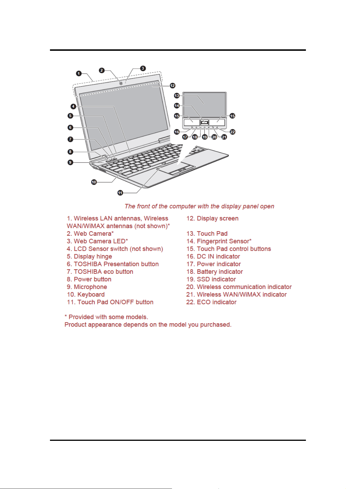
Figure 1-1 Front of the computer ............................................................................................. 9
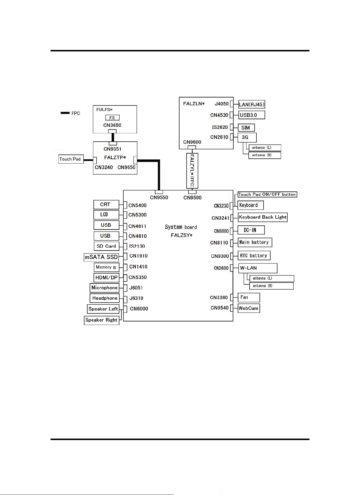
Figure 1-2 System unit configurations ................................................................................... 10
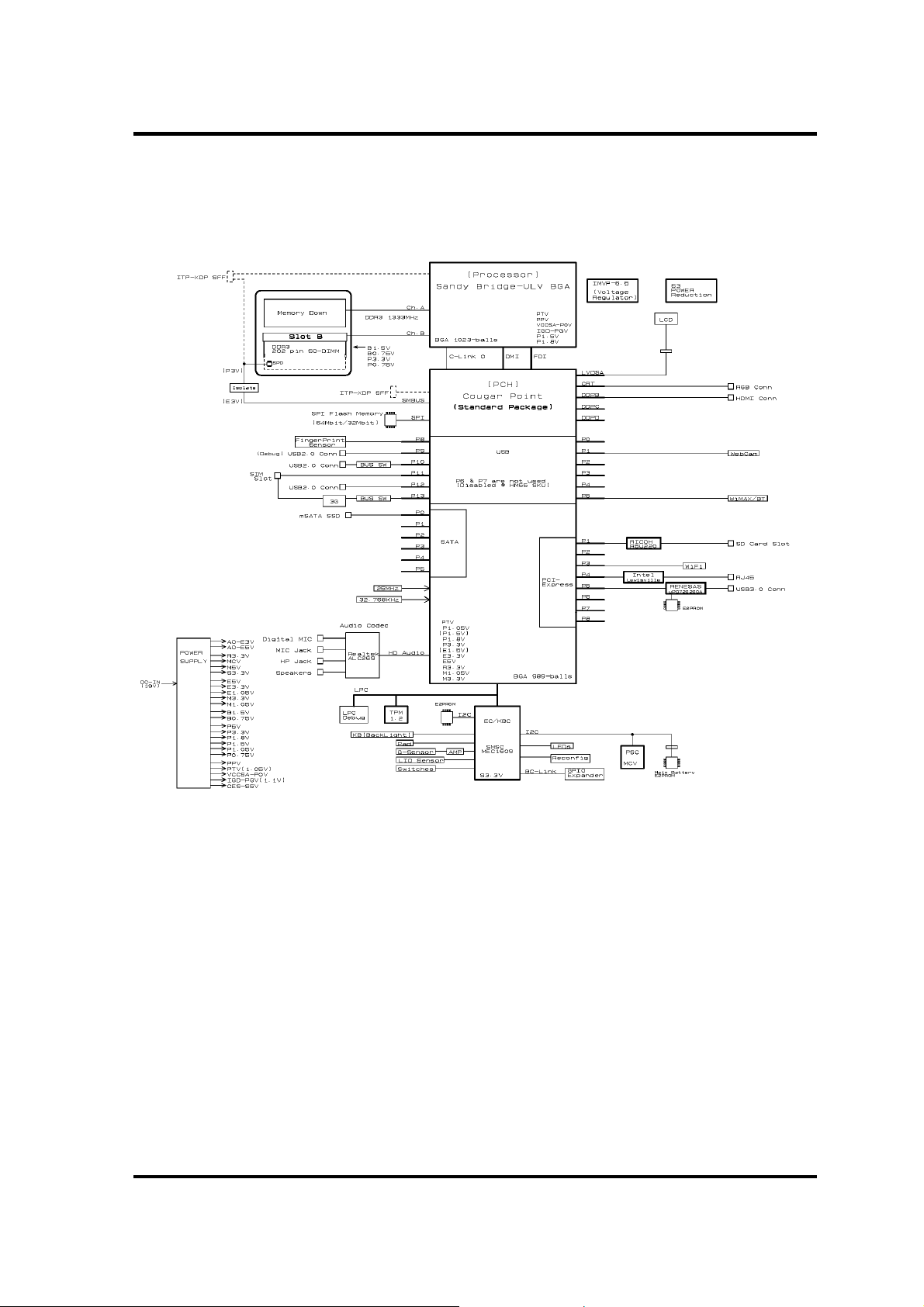
Figure 1-3 System unit block diagram ................................................................................... 11
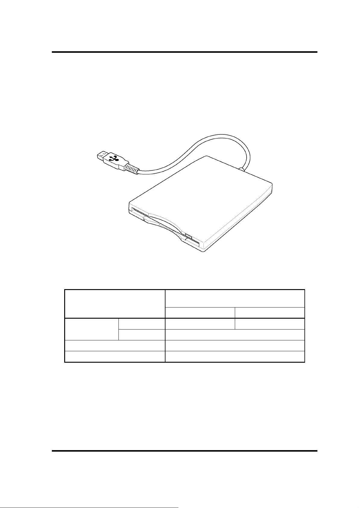
Figure 1-4 3.5-inch FDD (USB External)............................ ..... ..... ... ..... ...... .. ...... ..... ... ..... ..... 16
Figure 1- 5 mSATA SSD ....................................................................................................... 17
Figure 1- 6 Keyboard ............................................................................................................. 18
Figure 1- 7 LCD module ........................................................................................................ 19
Tables
Table 1-1 3.5-inch FDD specifications .................................................................................. 16
Table 1-2 mSATA SSD specifications ........ ................................... ................................... .. 17
Table 1-3 LCD module specifications ................................................................................... 19
Table 1-4 Power supply output rating ............................................... ... .................................. 21
Table 1-5 Battery specifications ............................................................................................ 22
Table 1-6 Time required for charges ..................................................................................... 23
Table 1-7 Data preservation time ........................................................................................... 24
Table 1-8 RTC battery charging/data preservation time .................................................. ..... 24
Table 1-9 AC adapter specifications ...................................................................................... 25
1-4 [CONFIDENTIAL] PORTEGE Z830 Satellite Z830 Series Maintenance Manual (960-883)
Page 17

1 Hardware Overview
1.1 Features
The Toshiba PORTEGE Z830 Satelli t e Z830 Series Personal Computer uses extensive Large
Scale Integration (LSI), and Complementary Metal-Oxide Semiconductor (CMOS)
technology extensively to provide compact size, minimum weight, low power usage and high
reliability. This computer incorporates the following features.
There some models and options. Refer to the Parts List for the configuration of each model
and options.
Microprocessor
The Toshiba PORTEGE Z830 Satellite Z830 Series computer is equipped with an
®
Processor.
Intel
The PC comes in with one of the following speeds:
Intel (Sanday Bridge DC 2+2 BGA ULV )
Core Frequency
1.80GB
System Bus
Frequency
L2 Cache
Size
Turbo number of cores /
number of threads
1333MHz 4MB 2.9 0GHz 2/4
ULV Core i7-2677M
1.70GB
1333MHz 3MB 2.70 GHz 2/4
ULV Core i5-2557M
1.60GB
1333MHz 3MB 2.30GHz 2/4
ULV Core i5-2467M
1.40GB
1333MHz 3MB - 2/4
ULV Core i3-2367M
Memory
One DDR3-1333 SDRAM slots. Memory modules can be installed to provide a maximum
of 8GB. Memory modules are available in2048MB, 4096MB and 8192GB sizes.
Total memory size becomes the sum total of on-board memory (2GB or 4GB) and
memory module size.
The maximum size of a memory is set to 12GB.
PORTEGE Z830 Satellite Z830 Series Maintenance Manual (960-883) [CONFIDENTIAL] 1-5
Page 18

1 Hardware Overview
Chipset
Toshiba PORTEGE Z830 Satellite Z830 Series computer is Equipped with Intel Cougar
Point QM67 (AMT model) or HM65 (Non-AMT model).
VGA Controller
The PC comes in with one of the following types:
The internal graphics controller in Intel Processor (Core i*) is used.
mSATA SSD
Some models are equipped with an mSATA type "Solid State Drive (SSD)" instead of a
hard disk drive.
64GB/128GB/
USB FDD
A 3.5-inch USB FDD accommodates 2HD (1.44MB) or 2DD (720KB) disks.
Display
The PC comes in with one of the following types:
33.8cm (13.3”) LCD screen, 16 million colors, configured with the following resolution:
HD, 1366 horizontal x 768 vertical pixels
Interface
To external monitor via - RGB connector and HDMI connector
Keyboard
The computer's keyboard layouts are compatible with a 104/105-key enhanced keyboard
- by pressing some keys in combination, all of the 104/105-key enhanced keyboard
functions can be performed on the computer.
Touch Pad
A Touch Pad and control buttons in the palm rest enable control of the on-screen pointer
and scrolling of windows.
1-6 [CONFIDENTIAL] PORTEGE Z830 Satellite Z830 Series Maintenance Manual (960-883)
Page 19

1 Hardware Overview
Batteries
The computer has two batteries: a rechargeable Lithium-Ion main battery pack and RTC
battery (that backs up the Real Time Clock and CMOS memory.
Universal Serial Bus (USB2.0)
Two Universal Serial Bus ports, which comply to the USB 2.0 standard, are provided on
the right hand side of the computer.
Universal Serial Bus(USB 2.0 or 3.0) port
One Universal Serial Bus port, which complies to the USB 2.0 or 3.0 standard, is
provided on the left side of the computer.
The USB port type may vary depending on the model you purchased. The Port with blue
color is USB 3.0 port.
The USB 2.0 port is compliant with USB 2.0 standard and not compatible with USB 3.0
devices.
The USB 3.0 port is compliant with USB 3.0 standard and backward compatible with
USB 2.0 devices.
External monitor (RGB) port
This port provides 15-pin, analog VGA port. This port allows you to connect an external
monitor to the computer.
HDMI out port
HDMI out port can connect with Type A connector HDMI cable. HDMI cable can send
video and audio signals.
SD Media slot
This slot lets you insert an SD™/SDHC™ memor y card, miniSD™/mi croSD™ Card,
and MultiMediaCard
Fingerprint sensor(Some models)
The computer is equipped with a fingerprint sensor and fingerprint authentication utility.
They enable only person who has registered his/her fingerprint to use the computer.
PORTEGE Z830 Satellite Z830 Series Maintenance Manual (960-883) [CONFIDENTIAL] 1-7
Page 20

1 Hardware Overview
Sound system
The sound system is equipped with the following features:
Stereo speakers
Built-in microphone
Stereo headphone jack
External microphone jack
External Headphone jack
Internal LAN
The computer has built-in support for Ethernet LAN (10 megabits per second, 10BASET), Fast Ethernet LAN (100 megabits per second, 100BASE-TX) and Gigabit Ethernet
LAN (1000 megabits per second, 1000BASE-T).
Wireless LAN
Some computers in this series are equipped with a Wireless LAN module that is
compatible with other LAN systems based on Direct Sequence Spread
Spectrum/Orthogonal Frequency Division Multiplexing radio technolo gy that complies
with the IEEE 802.11 Standard.
Bluetooth
Some computers in this series have Bluetooth wireless communication function which
eliminates the need for cables between electronic devices such as computers, printers and
mobile phones. When it is enabled, Bluetooth provides the wireless personal area
network environment which is safe and trustworthy, that is quick and easy.
Web Camera
Web Camera is a device that allows you to record video or take photographs with your
computer. You can use it for video chatting or video conferences using a communication
tool such as Windows Live Messenger. TOSHIBA Web Camera Application will help you
to add various video effects to your video or photograph.
3G
Some computers in this series are equipped with a 3G module.
1-8 [CONFIDENTIAL] PORTEGE Z830 Satellite Z830 Series Maintenance Manual (960-883)
Page 21
1 Hardware Overview
Figure 1-1 Front of the computer
PORTEGE Z830 Satellite Z830 Series Maintenance Manual (960-883) [CONFIDENTIAL] 1-9
Page 22
1 Hardware Overview
The system unit configuration is shown in fi gure 1-2
Figure 1-2 System unit configurations
1-10 [CONFIDENTIAL] PORTEGE Z830 Satellite Z830 Series Maintenance Manual (960-883)
Page 23
1 Hardware Overview
1.2 System Unit Block Diagram
Figure 1-3 is a block diagram of the system unit.
Figure 1-3 System unit block diagram
PORTEGE Z830 Satellite Z830 Series Maintenance Manual (960-883) [CONFIDENTIAL] 1-11
Page 24

1 Hardware Overview
The system unit is composed of the following major components:
Microprocessor
The Toshiba PORTEGE Z830 Satellite Z830 Series computer is equipped with an
®
Processor.
Intel
The PC comes in with one of the following speeds:
Intel (Sanday Bridge DC 2+2 BGA ULV )
Core Frequency
1.80GB
System Bus
Frequency
L2 Cache
Size
Turbo number of cores /
number of threads
1333MHz 4MB 2.9 0GHz 2/4
ULV Core i7-2677M
1.70GB
1333MHz 3MB 2.70 GHz 2/4
ULV Core i5-2557M
1.60GB
1333MHz 3MB 2.30GHz 2/4
ULV Core i5-2467M
1.40GB
1333MHz 3MB - 2/4
ULV Core i3-2367M
Memory
One DDR3-1333 SDRAM slots. Memory modules can be installed to provide a maximum
of 8GB. Memory modules are available in2048MB, 4096MB and 8192GB sizes.
- 204-pin slot
- DDR3-1333 support
Total memory size becomes the sum total of on-board memory (2GB or 4GB) and
memory module size.
The maximum size of a memory is set to 12GB.
1-12 [CONFIDENTIAL] PORTEGE Z830 Satellite Z830 Series Maintenance Manual (960-883)
Page 25

1 Hardware Overview
Chipset
(1)HM65 (Non-AMT)
(2)QM67 (AMT)
・989-ball 25×25mm FCBGA Package
VGA Controller
The PC comes in with one of the following types:
The internal graphics controller in Intel Processor (Core i*) is used..
LAN Controller
This controller has the following functions:
Support only a Gigabit Ethernet.
RJ45x1 port (with LED), docking connector (branch) 1 port.
WOL support (from S3, S4, and S5)
LAN controller
Made in
Intel Lewisville (WG82579V/LM(AMT)): PCI-Ex Connection
AMT7.0 support (BTO correspondence)
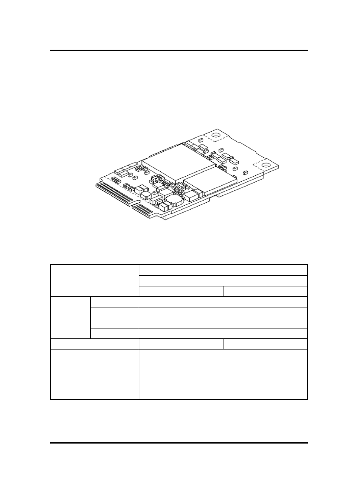
Wireless LAN or Bluetooth
One PCI Express Mini Card slot1(Half size)
802.11 b/g/n: Intel 802.11(b/g/n)13ch-CP 1x2 MOW-HMC
802.16e(b/g/n)WiMAX KelseyPeak :
Intel 802.16e(b/g/n)WiMAX KelseyPeak
Intel 802.16e(b/g/n)WiMAX KelseyPeak(Best Buy)
802.11 a/b/g/n +WiMAX (Kilmer Peak):
Intel 802.16e(a/g/n)13ch+WiMAX-KP 2x2 MOW-HMC
Atheros 802.11 a/g/n: Atheros 802.11(a/g/n)13ch-HB116 MOW-HMC
Atheros 802.11 b/g/n: Atheros 802.11(b/g/n)13ch-HB125 MOW-HMC
WOWL support (only Intel module)
PORTEGE Z830 Satellite Z830 Series Maintenance Manual (960-883) [CONFIDENTIAL] 1-13
Page 26

1 Hardware Overview
WLAN/Bluetooth combo
Atheros 802.11(b/g/n)WB195-HMC w/ BT V3.0+HS
Intel a/g/n(2x2) RP2 MOW-HMC w/ BT V3.0+EDR
3G
One PCI Express Mini Card slot1(Half size)
HSPA 3G HSPA (H5321gw) Ericsson made
USB I/F connection
SD Media Controller slot
Card slotx1
SD, mini SD (w/ adapter),Micro SD (w/adapter)
SD boot is No-supporting.
SD IO is No-supporting.
SDHC/SDXC is supporting.
Controller : RICOH R5U220-QFN48P
Sound Controller
PCH built-in HD Audio Link (Intel High Definition Audi o I / F)+RealTek ALC269Q
-VR5-GR
Amplifier:Realtek ( ALC269Q-VB5-GR ) Codec
Built-in microphone :On board
Built-in speaker: Stereo
External monophonic microphone input plug
Stereo headphone jack
Digital volume (Hot key type)
Camera
It is BTO correspondence by the built-in microphone and a set.
Connection interface: USB I/F connection
Product made from Liteon for 0.3M (VGA)
1-14 [CONFIDENTIAL] PORTEGE Z830 Satellite Z830 Series Maintenance Manual (960-883)
Page 27

1 Hardware Overview
Product made from Liteon for 1.3M (HD)
Other chips
Clock generator: ICS9LVRS394CKLFT (Made by Integrated Device Technology)
EC/KBC: MEC1609-PZP(REVISION.D) (Made by standard micro system)
PSC: TMP86FS49BUG (made by Toshiba)
TPM: SLB9635 TT 1.2FW3.17 (made by Infineon)
Sensor
Temperature reset IC :105-degree-C type
Thermistor: Four places (CPU, Memory, for normal temperature measurement, 3G)
Magneto metric sensor :
Use it as a LCD opening-and-closing sensor (ferrite magneto system).
Fingerprint sensor : Made by Authen Tec.
It mounts between the Touchpad buttons.
PORTEGE Z830 Satellite Z830 Series Maintenance Manual (960-883) [CONFIDENTIAL] 1-15
Page 28
1 Hardware Overview
1.3 3.5-inch Floppy Disk Drive (USB External)
The 3.5-inch FDD is a thin, high-performance reliable drive that supports 720KB (formatted)
2DD and 1.44MB (formatted) 2HD disks.
The FDD is shown in figure 1-4. The specifications for the FDD are listed in Table 1-1.
Figure 1-4 3.5-inch FDD (USB External)
Table 1-1 3.5-inch FDD specifications
TEAC FD-05PUB-337
Items
720KB mode 1.44MB mode
Data transfer rate FDD part 250K bits/second 500K bits/second
USB Full speed mode (12M bits/second)
Disk rotation speed 300rpm
Track density 5.3 track/mm (135TPI)
(G8AC0000B320)
1-16 [CONFIDENTIAL] PORTEGE Z830 Satellite Z830 Series Maintenance Manual (960-883)
Page 29
1 Hardware Overview
1.4 mSATA SSD
Some models are equipped with an mSATA ™ (mini SATA) type "Solid State Drive
(SSD)" instead of a hard disk drive.
The computer supports a 64GB and 128GB.
The specifications of mSATA SSD are listed by the table 1-4.
Figure 1- 5
Table 1-2
Items
G8BC0007W600 G8BC0007W120
Outline Width (mm)
Dimensions Height (mm)
Weight (g)
Storage size (formatted) 64GB 128GB
Data transfer speed
Length (mm) 50.95 +0/-0.3 mm
m
m
SATA SSD
SATA SSD specifications
Specifications
TOSHIBA
30.00 +0/-0.3 mm
3.95 mm (max.)
8.5 g (typ.)
Access time 0.5 ms (Typical)
Host Interface : 300MB/s
Sustained Data Read : Ave 180MB/s<*1>
Sustained Data Write : Ave 50MB/s<*1>
<*1> Under the condition of measurement with 128KB unit access
PORTEGE Z830 Satellite Z830 Series Maintenance Manual (960-883) [CONFIDENTIAL] 1-17
Page 30
1 Hardware Overview
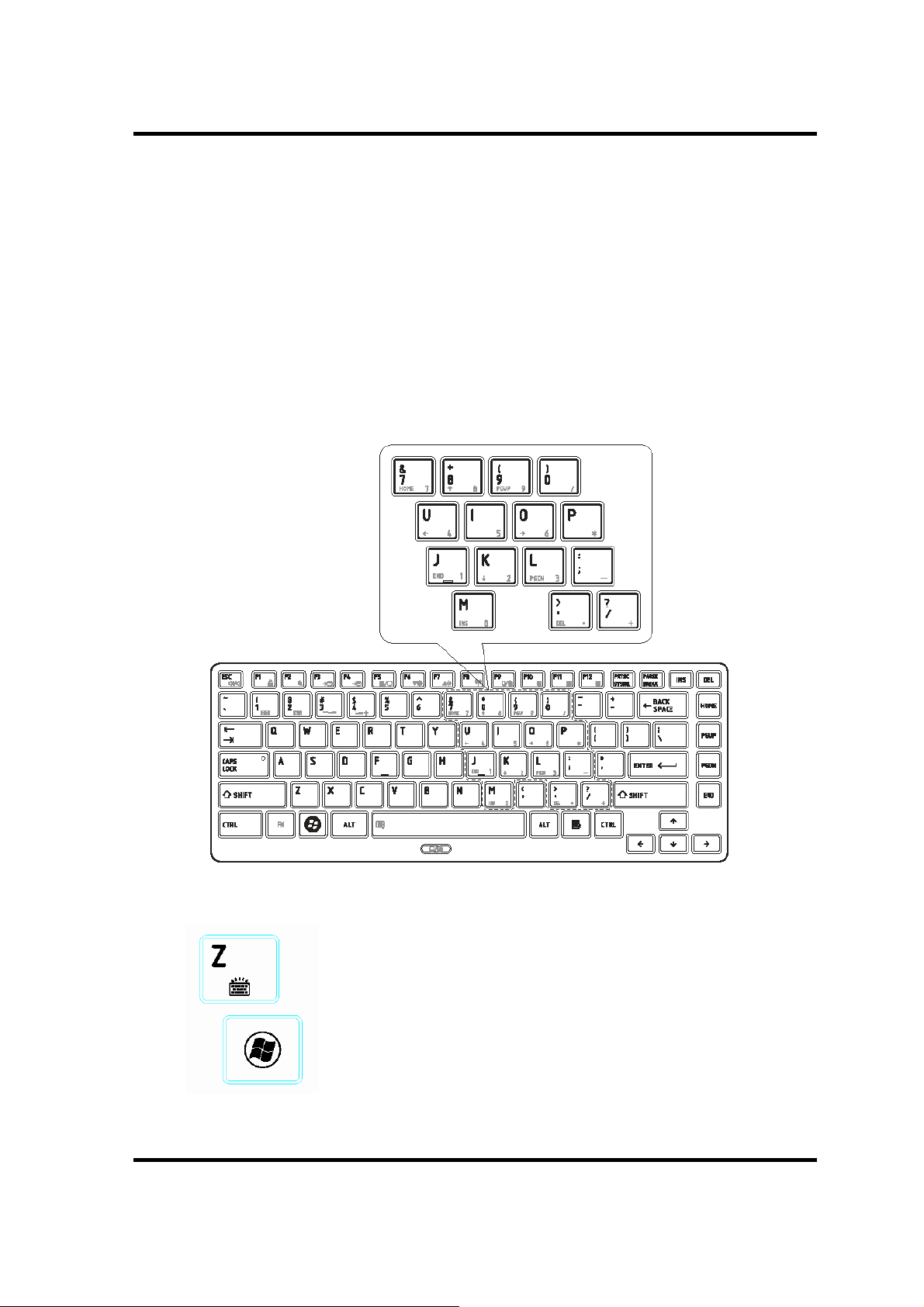
1.5 Keyboard
The computer's keyboard layouts are compatible with a 104/105-key enhanced keyboard - by
pressing some keys in combination, all of the 104/105-key enhanced keyboard functions can
be performed on the computer.
Figure 1-6 is a view of the keyboard.
See Appendix E about a layout of the keyboard.
Figure 1- 6 Keyboard
1-18 [CONFIDENTIAL] PORTEGE Z830 Satellite Z830 Series Maintenance Manual (960-883)
The stamp of a keyboard back light on & Windows-key
Page 31

1 Hardware Overview
1.6 TFT Color Display
The TFT color display consists of 13.3-inch HD LCD module.
1.6.1 LCD Module
The LCD module used for the TFT color display uses a backlight as the light source and can
display a maximum of 16M colors with 1,366 x 768 resolutions.
Figure 1-7 shows a view of the LCD module and Table 1-7 lists the specifications.
Figure 1- 7 LCD module
Item
Number of Dots
Dot pitch (mm)
Active area (mm)
Outline (mm)
Table 1-3 LCD module specifications
Samsung
13.3 HD 200 LD Non-CSV
G33C00072110
13.3 HD 200 LD CSV
G33C00071110
1,366 (W) x 768 (H)
0.2148(H)x0.2148(V)
293.42(H)x164.97(V) (13.3”diagonal )
306.3(H) x 177.7(V) x 2.85(Max)@PCB area
PORTEGE Z830 Satellite Z830 Series Maintenance Manual (960-883) [CONFIDENTIAL] 1-19
Page 32

1 Hardware Overview
1.7 Power Supply
The power supply supplies many different voltages to the system board and performs the
following functions:
1. Judges that the DC power supply (AC adapter) is connected to the computer.
2. Detects DC output and circuit malfunctions.
3. Controls the battery icon, and DC IN icon.
4. Turns the battery charging system on and off and detects a fully charged battery.
5. Turns the power supply on and off.
6. Provides more accurate detection of a low battery.
7. Calculates the remaining ba tt ery capacity.
8. Controls the transmission of the status signal of the main battery.
The power supply output rating is specified in Table 1-8
1-20 [CONFIDENTIAL] PORTEGE Z830 Satellite Z830 Series Maintenance Manual (960-883)
Page 33

1 Hardware Overview
Table 1-4 Power supply output rating
PORTEGE Z830 Satellite Z830 Series Maintenance Manual (960-883) [CONFIDENTIAL] 1-21
Page 34

1 Hardware Overview
1.8 Batteries
The computer has three types of batteries as follows:
Main battery pack
RTC battery
The battery specifications are listed in Table 1-9
Table 1-5 Battery specifications
Battery name Material Output
voltage
Main battery
G71C000CH310
RTC battery GDM710000069 NiMH 2.4 V 16 mAh
Lithium-Ion 10.8 V
Capacity
8Cell 47Wh
1.8.1 Main Battery
The removable main battery pack is the computer’s main power source when the AC adaptor
is not attached. The main battery maintains the state of the computer when the computer
enters in sleep mode.
1-22 [CONFIDENTIAL] PORTEGE Z830 Satellite Z830 Series Maintenance Manual (960-883)
Page 35

1 Hardware Overview
1.8.2 Battery Charging Control
Battery charging is controlled by a power supply microprocessor. The microprocessor
controls whether the charge is on or off and detects a full charge when the AC adaptor and
battery are attached to the computer. The system charges the battery.
Battery Charge
When the AC adaptor is attached, there are two types of charge: When the system is powered
off and when the system is powered on. Table 1-10 lists the charging time required for
charges.
Table 1-6 Time required for charges
Battery type Power on (hours) Power off (hours)
Battery (8Cell 47Wh ) about 3.5 to 8.0 About 3.0
NOTE: The time required when the system is powered on is affected by the amount of
power the system is consuming. Use of the fluorescent lamp and frequent disk
access diverts power and lengthens the charge time.
If any of the following occurs, the battery charge process stops.
1. The battery becomes fully charged.
2. The AC adaptor or battery is removed.
3. The battery or output voltage is abnormal.
PORTEGE Z830 Satellite Z830 Series Maintenance Manual (960-883) [CONFIDENTIAL] 1-23
Page 36

1 Hardware Overview
Data preservation time
When turning off the power in being charged fully, the preservation time is as
following Table 1-11.
Table 1-7 Data preservation time
Condition preservation time
Standby About 4 days (8Cell 47Wh)
Shutdown About 90 days(8Cell 47Wh )
1.8.3 RTC battery
The RTC battery provides power to keep the current date, time and other setup information
in memory while the computer is turned off. Table 1-12 lists the charging time and data
preservation period of the RTC battery.
Table 1-8 RTC battery charging/data preservation time
Status Time
Charging Time (power on) 10 hours
Data preservation period (full charge) 30 days
1-24 [CONFIDENTIAL] PORTEGE Z830 Satellite Z830 Series Maintenance Manual (960-883)
Page 37

1 Hardware Overview
1.9 AC Adapter
The AC adapter is also used to charge the batter y.
Table 1-13 lists the AC adapter specifications.
Table 1-9 AC adapter specifications
Parameter Specification
G71C000AR210
G71C000AT210
(2-pin)
Power 45W
Input voltage 100V/240V
Input frequency 50Hz to 60Hz
Input current 1.3 A (100V-240V)
B Output voltage 19V
Output current 2.37A
G71C000AS110
G71C000AU110
(3-pin)
Parameter Specification
G71C0009S210
G71C000AE212
(2-pin)
Power 65W
Input voltage 100V/240V
Input frequency 50Hz to 60Hz
Input current 1.5 A (100V-240V)
G71C0009S111
G71C000AE113
(3-pin)
B Output voltage 19V
Output current 3.42A
PORTEGE Z830 Satellite Z830 Series Maintenance Manual (960-883) [CONFIDENTIAL] 1-25
Page 38

1 Hardware Overview
1-26 [CONFIDENTIAL] PORTEGE Z830 Satellite Z830 Series Maintenance Manual (960-883)
Page 39

Troubleshooting Procedures
Chapter 2 Troubleshooting Procedures
PORTEGE Z830 Satellite Z830 Series Maintenance Manual (960-883) [CONFIDENTIAL] 2-1
Page 40

Troubleshooting Procedures
2
2-2 PORTEGE Z830 Satellite Z830 Series Maintenance Manual (960-883) [CONFIDENTIAL]
Page 41

Troubleshooting Procedures
Chapter 2 Contents
2 2-2
2.1 Troubleshooting ........................... ..................................................... ...................... 2-6
2.2 Troubleshooting Flowchart ..................................................................................... 2-8
2.3 Power Supply Troubleshooting .................................................... ......................... 2-13
2.3.1 Procedure 1 Power Status Check ........................................................ 2-13
2.3.2 Procedure 2 Error Code Check .. ................................ ......................... 2-15
2.3.3 Procedure 3 Connection Check ..................................... ..... ..... ...... .. .... 2-20
2.3.4 Procedure 4 Charging Check .. ................................ ... ......................... 2-21
2.3.5 Procedure 5 Replacement Check ....... ..... ... ..... ...... .. ...... ..... ... ..... ..... ... . 2-21
2.4 System Board Troubleshooting ............................................................................. 2-22
2.4.1 Procedure 1 Message Check . ..... ..... ... ..... ...... .. ...... ..... ... ..... ..... ... ..... ... . 2-23
2.4.2 Procedure 2 Debugging Port Check .................................................... 2-25
2.4.3 Procedure 3 Diagnostic Test Program Execution Check .................... 2-31
2.4.4 Procedure 4 Replacement Check ....... ..... ... ..... ...... .. ...... ..... ... ..... ..... ... . 2-31
2.5 USB FDD Troubleshooting .................................................................................. 2-32
2.5.1 Procedure 1 FDD Head Cleaning Check ... ................................ ... ...... 2-32
2.5.2 Procedure 2 Diagnostic Test Program Execution Check .................... 2-33
2.5.3 Procedure 3 Connector Check and Replacement Check ..................... 2-34
2.6 mSATA SSD Troubleshooting ............................................................................. 2-36
2.6.1 Procedure 1 Partition Check (Not Used) ............................................ 2-36
2.6.2 Procedure 2 Message Check . ..... ..... ... ..... ...... .. ...... ..... ... ..... ..... ... ..... ... . 2-37
2.6.3 Procedure 3 Format Check (Not Used) ...................................... ..... .... 2-38
2.6.4 Procedure 4 Diagnostic Test Program Execution Check .................... 2-39
2.6.5 Procedure 5 Connector Check and Replacement Check ..................... 2-40
2.7 Keyboard Troubleshooting ............................. ................................ .. .................... 2-41
2.7.1 Procedure 1 Diagnostic Test Program (and Windows)Execution
Check ............................ ........................ ..................... ........................ . 2-41
2.7.2 Procedure 2 Connector Check and Replacement Check ..................... 2-41
2.8 Touch pad Troubleshooting .................................................................................. 2-43
2.8.1 Procedure 1 Diagnostic Test Program Execution Check .................... 2-43
PORTEGE Z830 Satellite Z830 Series Maintenance Manual (960-883) [CONFIDENTIAL] 2-3
Page 42

Troubleshooting Procedures
2.8.2 Procedure 2 Connector Check and Replacement Check ..................... 2-43
2.9 Display Troubleshooting ....................................................................................... 2-45
2.10 LAN Troubleshooting ........................................................................................... 2-47
2.10.1 Procedure 1 Diagnostic Test Program Execution Check .................... 2-47
2.10.2 Procedure 2 Connector Check and Replacement Check ..................... 2-47
2.11 Wireless LAN or Wireless LAN +Bluetooth Troubleshooting ............................ 2-49
2.11.1 Procedure 1 Transmitting-Receiving Check ...................................... 2-49
2.11.2 Procedure 2 Antennas' Connection Check ................................ ... ...... 2-49
2.11.3 Procedure 3 Replacement Check ....................................................... 2-50
2.12 Sound Troubleshooting ......................................................................................... 2-51
2.12.1 Procedure 1 Diagnostic Test Program Execution Check .................... 2-51
2.12.2 Procedure 2 Connector Check ...................... .. ...... .. ...... ..... ... ..... ..... ... . 2-51
2.12.3 Procedure 3 Replacement Check ....................................................... . 2-52
2.13 SD Card Slot Troubleshooting .............................................................................. 2-53
2.13.1 Procedure 1 Check on Windows OS .......................................... ......... 2-53
2.13.2 Procedure 2 Connector Check and Replacement Check ..................... 2-53
2.14 Fingerprint sensor Troubleshooting ..................................... ..... ...... ..... ... ..... ..... ... . 2-54
2.15 Web camera Troubleshooting ................................................... ............................ 2-59
2.15.1 Procedure 1 Check on Windows OS .......................................... ......... 2-59
2.15.2 Procedure 2 Connector Check and Replacement Check ..................... 2-59
2.16 3G Troubleshooting ........................................................ ................................ .. .... 2-61
2.17 HDMI Troubleshooting ........................................................................................ 2-63
2.17.1 Procedure 1 Check on HDMI TV ...................................... ................. 2-63
2-4 PORTEGE Z830 Satellite Z830 Series Maintenance Manual (960-883) [CONFIDENTIAL]
Page 43

Troubleshooting Procedures
Figures
Figure 2-1 Troubleshooting flowchart (1/2) .......................................................................... 2-9
Tables
Table 2-1 Battery icon ........................................................ ... ................................ .............. 2-13
Table 2-2 DC IN icon ......................................... ... ................................ .. ............................ 2-14
Table 2-3 Error code ........................................................... ................................ ... .............. 2-16
Table 2-4 Debug port error status (1/2) pending ................................ ... .............................. 2-26
Table 2-5 FDD error code and status................................................................................... 2-33
Table 2-6 2.5” Hard disk drive error code and status ................................................. ... ...... 2-39
PORTEGE Z830 Satellite Z830 Series Maintenance Manual (960-883) [CONFIDENTIAL] 2-5
Page 44

Troubleshooting Procedures
pply
y
y
r
play
2.1 Troubleshooting
Chapter 2 describes how to determine which Field Replaceable Unit (FRU) in the computer is
causing the computer to malfunction. (The “FRU” means the replaceable unit in the field.)
The FRUs covered are:
1. Power su
stem Board 9. Wireless LAN +Bluetooth
2. S
3. USB FDD 10. Sound
4. mSATA SSD 11. SD Card slot
5. Ke
6. Touch pad 13. Web camerta
7. Dis
The Test Program operations are des cribed in Chapter 3. Detailed replacement procedures are
described in Chapter 4.
board 12. Fingerprint Senso
14. 3G
8. LAN 15. HDMI
NOTE:
1. Before replacing the system board, execute subtest03 “DMI information save”
in 3.3 Setting of the hardware configuration in order to save the DMI
information from system board to floppy disk.
2. After replacing the system board, execute the subtest04 “DMI information
recovery” and subtest08 “System co nfiguration display” in 3.3 Setting of the
hardware configuration in order to copy the DMI information and system
information from the floppy disk.
3. Also update with the latest EC/KBC as described in Appendix H “EC/KBC
Rewrite Procedures”.
4. After replacing the LCD, update with the latest EC/KBC as described in
Appendix H “EC/KBC Rewrite Procedures” to set the SVP parameter.
The implement for the Diagnostics procedu r es is referred to Chapter 3. Also, following
implements are necessary:
1. Phillips screwdrivers (For repl ace ment procedures)
2. Implements for debugging port check
Toshiba MS-DOS system FD
RS-232C cross cable
Test board with debug port test cable
PC for displaying debug port test result
2-6 PORTEGE Z830 Satellite Z830 Series Maintenance Manual (960-883) [CONFIDENTIAL]
Page 45

Troubleshooting Procedures
There are following two types of connections in the figure of board and module connection in
and after 2.3 Power Supply Troubleshooting.
(1) Cable connection is described in the figure as line.
(2) Pin connection is described in the figure as arrow.
<e.g> Connection of modem
PORTEGE Z830 Satellite Z830 Series Maintenance Manual (960-883) [CONFIDENTIAL] 2-7
Page 46

Troubleshooting Procedures
2.2 Troubleshooting Flowchart
Use the flowchart in Figure 2-1 as a guide f or de termining which troubles h o ot i n g procedures
to execute. Before going thr ou g h the flo wchart steps, verify the follow ing:
Ask him or her to enter the password if a password is registe red.
Verify with the customer that Toshiba Windows is installed on the hard disk. Non-
Windows operating systems can cause the computer to malfunction.
Make sure all optional equipment is removed from the computer.
2-8 PORTEGE Z830 Satellite Z830 Series Maintenance Manual (960-883) [CONFIDENTIAL]
Page 47

Troubleshooting Procedures
Figure 2-1 Troubleshooting flowchart (1/2)
PORTEGE Z830 Satellite Z830 Series Maintenance Manual (960-883) [CONFIDENTIAL] 2-9
Page 48

Troubleshooting Procedures
Insert the diagnostic disk into the
ODD. Then hold down the C key
and start the computer to run the
diagnostic test program.
Figure 2-1 Troubleshooting flowchart (2/2)
2-10 PORTEGE Z830 Satellite Z830 Series Maintenance Manual (960-883) [CONFIDENTIAL]
Page 49

Troubleshooting Procedures
If the diagnostics program cannot detect an error, the problem may be intermittent. The Test
program should be executed several times to isolate the problem. Check the Log Utilities
function to confirm which diagnostic test detected an error(s), then perform the appropria t e
troubleshooting procedures as follows:
1. If an error is detected on the power supply, perform the power supply Troubl eshooting
Procedures in Sectio n 2.3.
2. If an error is detected on the system test, memory test, display test, CD-ROM/DVD-
ROM test, expansion test, real timer test, sound test or Modem/LAN/Bluetooth
/IEEE1394 test, perform the System Board Troubleshooting Procedures in Sec tio n 2. 4.
3. If an error is detected on the flo p py disk test, perform the USB FDD Troubleshooting
Procedures in Sectio n 2.5.
4. If an error is detected on the hard disk test, perform the mSATA SSD Troubleshooting
Procedures in Sectio n 2.6.
5. If an error is found on the keyboard test (DIAGNOSTICS TEST) and pressed key
display test (ONLY ONE TEST), perform the Keyboard Troubleshooting Procedures
in Section 2.7.
6. If an error is found on the touch pa d test (ONLY ONE TEST), perform the touch pad
Troubleshooting Procedures in Section 2.8.
7. If an error is detected on the display test, perform the Display Troubleshooting
Procedures in Sectio n 2.9.
8. If an error is detected on the LAN te st, perform the LAN Troubleshooti ng Procedures
in Section 2.10.
9. If an error is detected on the wireless LAN test, perform the Wireless LAN or Wireless
LAN +Bluetooth Troubleshooting Procedures in Section 2.11.
10. If an error is detecte d on th e sound test, perform the Sound Trou ble shooting
Procedures in Sectio n 2.12.
11. If an error is detected o n the sound test, perform the SD Card Troubleshooting
Procedures in Sectio n 2.13.
12. If a malfunction is detected on the fingerprint sensor, perform the Fingerprint Sensor
Troubleshooting Procedures in Section 2.14.
13. If a malfunction is detected on the Web camera, perform the Web camera
Troubleshooting Procedures in Section 2.15
14. If a malfunction is detected on the 3G, perform the 3G Troubleshooting Procedures in
Section 2.16
PORTEGE Z830 Satellite Z830 Series Maintenance Manual (960-883) [CONFIDENTIAL] 2-11
Page 50

Troubleshooting Procedures
15. If a malfunction is detected on the HDMI, perform the HDMI Troubleshooting
Procedures in Sectio n 2.17
2-12 PORTEGE Z830 Satellite Z830 Series Maintenance Manual (960-883) [CONFIDENTIAL]
Page 51

Troubleshooting Procedures
2.3 Power Supply Troubleshooting
The power supply controller controls many functions and components. To determine if th e
power supply is functioning properly, start with Procedure 1 and continue with the other
Procedures as instructed. The proce d ures described in this section are:
Procedure 1: Power Status Check
Procedure 2: Error Code Check
Procedure 3: Connection Check
Procedure 4: Charging Check
Procedure 5: Replacement Check
2.3.1 Procedure 1 Power Status Check
The following icons indicate the power su pp ly status:
Battery icon
DC IN icon
The power supply controller displays the power supply status with the Battery icon and the
DC IN icon as listed in the tables below.
Table 2-1 Battery icon
Battery icon Power supply status
Lights orange Battery is charged and the external DC is input. It has no
relation with ON/OFF of the system power.
Lights blue Ba ttery is f ully ch arged a n d t he exte rnal DC is input. It has
no relation with ON/OFF of the system power.
Blinks orange
(even intervals)
Blinks orange once
(at being switched on)
Doesn’t light Any condition other than those above.
The battery level is low while the system power is ON.
The system is driven by only a battery and the battery level
is low.
PORTEGE Z830 Satellite Z830 Series Maintenance Manual (960-883) [CONFIDENTIAL] 2-13
Page 52

Troubleshooting Procedures
Table 2-2 DC IN icon
DC IN icon Power supply status
Lights blue DC power is being supplied from the AC adapter.
Blinks orange Power supply malfunction*1
Doesn’t light Any condition other than those above.
*1 When the power supply controller detects a malfunction, the DC IN icon blinks
orange. It shows an error code.
When the icon is blinking, perform the following procedure.
1. Remove the battery pack and the AC adapter.
2. Re-attach the battery pack and the AC adapter.
If the icon is still blinking after the operation above, check the followings:
Check 1 If the DC IN icon blinks orange, go to
Procedure 2.
Check 2 If the DC IN icon does not light, go to Procedure 3.
Check 3 If the battery i c on does not light orange or blue, go to Procedure 4.
NOTE: Use a supplied AC adapter G71C000A5210 (2-pin)/ G71C000A6210 (3-pin).
2-14 PORTEGE Z830 Satellite Z830 Series Maintenance Manual (960-883) [CONFIDENTIAL]
Page 53

Troubleshooting Procedures
2.3.2 Procedure 2 Error Code Check
If the power supply microprocessor detects a malfunction, the DC IN icon blinks orange. The
blink pattern indicates an error as shown below.
Start Off for 2 seconds
Error code (8 bit)
“1” On for one second
“0” On for half second
Interval between data bits Off for half second
The error code begins with the least significant digit.
Example: Error code 11h (Error codes are g i ven in hexadecimal format.)
Start
PORTEGE Z830 Satellite Z830 Series Maintenance Manual (960-883) [CONFIDENTIAL] 2-15
Page 54

Troubleshooting Procedures
Check 1 Convert the DC IN icon blink pattern into the hexadecimal error code and compare
it to the tables below. Then go to Check 2.
Table 2-3 Error code
Error code Where error occurs
1*h DC Power (AC Adapter)
2*h Main battery
3:h 2nd battery
4*h S3V output
5*h E5V output
6*h E3V output
7*h 1R5-B1V output
8*h PPV output
9*h 1R05-E1V output
A*h IGD-PGV output
B*h
C*h VCCSA_P0V output
D*h PTV output
E*h F*h -
-
DC power supply (AC adapter)
Error code Meaning
10h AC Adapter output voltage is over 20.92V.
11h Common Dock output voltage is over 20.92V...
12h Current from the DC power supply is over 3.89A.
13h Current from the DC power supply is over 0.5A when there is no load.
14h The compensation value of [0A] is not within the limits from design data (±
481mA).
2-16 PORTEGE Z830 Satellite Z830 Series Maintenance Manual (960-883) [CONFIDENTIAL]
Page 55

Troubleshooting Procedures
Main Battery
Error code Meaning
22h Main battery discharge current is over 0.5A.
23h Main battery charge current is over 3.1A
24h The compensation value of [0A] is not within the limits from design data (±
400mA).
25h Main battery charge current is over 0.3A when the charging is off.
2nd Battery
Error code Meaning
32h Second battery discharge current is over 0.5A.
33h Second battery charge current is over 3.1A
34h The compensation value of [0A] is not within the limits from design data (±
400mA)
35h Second battery charge current is over 0.3A
S3V output
Error code Meaning
40h S3V voltage is over 3.47V.
45h S3Vvoltage is under 3.14V.
46h S3V voltage is under 3.14V or less when the computer is booting up.
E5V output
Error code Meaning
50h E5V voltage is over 6.00V.
51h E5V voltage is under 4.50V when the computer is powered on.
52h E5V voltage is under 4.50V when the computer is booting up.
54h E5V voltage is under 4.50V when EV power is maintained.
PORTEGE Z830 Satellite Z830 Series Maintenance Manual (960-883) [CONFIDENTIAL] 2-17
Page 56

Troubleshooting Procedures
E3V output
Error code Meaning
60h E3V voltage is over 3.96V.
61h E3V voltage is under 2.81V when the computer is powered on.
62h E3V voltage is under 2.81V when the computer is booting up.
64h E3V voltage is under 2.81V when EV power is maintained.
1R5-B1V output
Error code Meaning
70h 1R5-B1V voltage is over 1.80V.
71h 1R5-B1V voltage is under 1.28V when the computer is powered on.
72h 1R5-B1V voltage is under 1.28V when the computer is booting up.
73h 1R5-B1V power supply showed the normal range at the time of BV power supply
stop.
PPV output
Error code Meaning
80h PPV voltage is over 1.80V.
81h PPV voltage is under 0.00V when the computer is powered on.
82h PPV voltage is under 0.55V when the computer is booting up.
1R05-E1V output
Error code Meaning
90h 1R05-E1V voltage is over 1.26V.
91h 1R05-E1V voltage is under 0.89V when the computer is powered on.
92h 1R05-E1V voltage is under 0.89V when the computer is booting up.
94h 1R05-E1V voltage is under 0.89V when EV power is maintained.
2-18 PORTEGE Z830 Satellite Z830 Series Maintenance Manual (960-883) [CONFIDENTIAL]
Page 57

Troubleshooting Procedures
IGD-PGV output
Error code Meaning
A0h IGD-PGV voltage is over 1.80V.
A1h IGD-PGV voltage is under 0.00V when the computer is powered on.
A2h IGD-PGV voltage is under 0.00V when the computer is booting up.
VCCSA-P0V output
Error code Meaning
C0h VCCSA-P0V voltage is over 1.08V.
C1h VCCSA-P0V voltage is under 0.64V when the computer is powered on.
C2h VCCSA-P0V voltage is under 0.64V when the computer is booting up.
PTV output
Error code Meaning
D0h
D1h
D2h
PTV voltage is over 1.26V.
PTV voltage is under 0.89V when the computer is powered on.
PTV voltage is under 0.89V when the computer is booting up.
Miscellaneous
Error code Meaning
F0h The sub clock does not oscillate.
Check 2 In the case of error code 10h or 12h:
Make sure the AC adapter and AC power cord are firmly plugged into the DC
IN 19 V socket and wall outlet. If the cables are connected firmly, go to the
following step.
Connect a new AC adapter and AC power cord. If the problem still occurs, go
to Procedure 5.
Check 3 In the case of error code 21h:
PORTEGE Z830 Satellite Z830 Series Maintenance Manual (960-883) [CONFIDENTIAL] 2-19
Page 58

Troubleshooting Procedures
Go to Procedure 3.
Check 4 For any other errors, go to Procedure 5.
2.3.3 Procedure 3 Connection Check
The wiring diagram related to the power supply is shown below:
Any of the connectors may be disconnected. Perform Check 1.
Check 1 Make sure the AC adapter and the AC power cord are firmly plugged into the DC
IN jack and wall outlet. If these cables are connected firmly, go to Check 2.
Check 2 Replace the AC adapter and the AC power cord with new ones.
If the DC IN icon does not light, go to Procedure 5.
If the battery icon does not light, go to Check 3.
Check 3 Make sure the battery pack is installed in the computer correctly. If the battery is
properly installed and the battery icon still does not light, go to Procedure 4.
2-20 PORTEGE Z830 Satellite Z830 Series Maintenance Manual (960-883) [CONFIDENTIAL]
Page 59

Troubleshooting Procedures
2.3.4 Procedure 4 Charging Check
Check if the power supply controller charges the battery pack properly. Perform the following
procedures:
Check 1 Make sure the AC adapter is firmly plugged into the DC IN jack.
Check 2 Make sure the battery pack is properly installed. If it is properly installed, go to
Check 3.
Check 3 The battery pack may be completely discharged. Wait a f e w minutes to charge the
battery pack while connecting the batte ry p ack and the AC adapter. If the battery
pack is still not charged, go to Check 4.
Check 4 The battery’s temperature is too high or low. Leave the battery for a while to adjust
it in the right temperature. If the battery pack is still not charged, go to Check 5.
Check 5 Replace the battery pack with a new one. If the battery pack is still not charged, go
to Procedure 5.
2.3.5 Procedure 5 Replacement Check
The power is supplied to the system board by the AC adapter. If either the AC adapter or the
system board was damaged, pe rform the following Check s.
To disassemble the computer, fo llow the steps described in Chapter 4, Replacement
Procedures.
When AC adapter is connected:
Check 1 AC adapter may be faulty. Replace the AC adapter with a new one. If the problem
still occurs, perform Check 2.
Check 2 System board may be faulty. Replace the system board with a new one.
When AC adapter is not connected:
(When driving with battery pack)
Check 1 Battery pack may be faulty. Replace it with a new one. If the problem still occurs,
perform Check 2.
Check 2 System board may be faulty. Replace it with a new one.
PORTEGE Z830 Satellite Z830 Series Maintenance Manual (960-883) [CONFIDENTIAL] 2-21
Page 60

Troubleshooting Procedures
2.4 System Board Troubleshooting
This section describes how to determine if the system board is malfunctioning or not. Start
with Procedure 1 and continue with the other procedures as instructed. The procedu res
described in this section are:
Procedure 1: Message Check
Procedure 2: Debugging Port C he c k
Procedure 3: Diagnostic Test Program Execution Check
Procedure 4: Replacement Check
2-22 PORTEGE Z830 Satellite Z830 Series Maintenance Manual (960-883) [CONFIDENTIAL]
Page 61

Troubleshooting Procedures
2.4.1 Procedure 1 Message Check
When the power is turned on, the system performs the Initial Reliability Test (IRT) installed
in the BIOS ROM. The IRT tests each IC on the system board and initializes it.
If an error message is shown on the display, perform Check 1.
If there is no error message, go to Procedure 2.
If MS-DOS or Windows OS is properly loaded, go to Procedure 4.
Check 1 If one of the following error messages is displayed on the screen, press the F1 key
as the message instructs. These err o rs occur when the system configura tion
preserved in the RTC memory (CMOS type memory) is not the same as the actual
configuration or when the data is lost.
If you press the F1 key as the message instructs, the SETUP screen appears to set
the system configuration. If error me ssa ge (b) appears often when the power is
turned on, replace the RTC battery. If any other error message is dis pla yed,
perform Check 2.
(a) *** Bad HDD type ***
Check system. Then press [F1] key ......
(b) *** Bad RTC battery ***
Check system. Then press [F1] key ......
(c) *** Bad configuration ***
Check system. Then press [F1] key ......
(d) *** Bad memory size ***
Check system. Then press [F1] key ......
(e) *** Bad time function ***
Check system. Then press [F1] key ......
(f) *** Bad check sum (CMOS) ***
Check system. Then press [F1] key ......
(g) *** Bad check sum (ROM) ***
Check system. Then press [F1] key ......
Check 2 If the following error message is displayed on t he scree n, press any key as the
message instructs.
The following error message appears when data stored in RAM under the resume
function is lost because the battery has become discharged or the system boar d is
damaged. Go to Procedure 3.
WARNING: RESUME FAILURE.
PRESS ANY KEY TO CONTINUE.
PORTEGE Z830 Satellite Z830 Series Maintenance Manual (960-883) [CONFIDENTIAL] 2-23
Page 62

Troubleshooting Procedures
If any other error message displays, perform Check 3.
Check 3 The IRT checks the system board. When the IRT detects an error, the system stops
or an error message appears.
If one of the following error messages (1) through (17), (23) or (24) is displayed,
go to Procedure 4.
If error message (18) is displayed, go to the Keyboard Troubleshooting Procedures.
If error message (19), (20) or (21 ) is displayed, go to the HDD Troublesho oti ng
Procedures.
If error message (22) is displayed, go to the USB FDD Troubleshooting Procedures.
(1) PIT ERROR
(2) MEMORY REFRESH ERROR
(3) TIMER CH.2 OUT ERROR
(4) CMOS CHECKSUM ERROR
(5) CMOS BAD BATTERY ERROR
(6) FIRST 64KB MEMORY ERROR
(7) FIRST 64KB MEMORY PARITY ERROR
(8) VRAM ERROR
(9) SYSTEM MEMORY ERROR
(10) SYSTEM MEMORY PARITY ERROR
(11) EXTENDED MEMORY ERROR
(12) EXTENDED MEMORY PARITY ERROR
(13) DMA PAGE REGISTER ERROR
(14) DMAC #1 ERROR
(15) DMAC #2 ERROR
(16) PIC #1 ERROR
(17) PIC #2 ERROR
(18) KBC ERROR
(19) HDC ERROR
(20) HDD #0 ERROR
(21) HDD #1 ERROR
(22) NO FDD ERROR
(23) TIMER INTERRUPT ERROR
(24) RTC UPDATE ERROR
2-24 PORTEGE Z830 Satellite Z830 Series Maintenance Manual (960-883) [CONFIDENTIAL]
Page 63

Troubleshooting Procedures
2.4.2 Procedure 2 Debugging Port Check
Check the D port status by a debug port test. The tool for debug port test is shown below.
Figure 2-1 A set of tool for debug port test
1. Not a Serial Port model should connect a debug port test cable to connector CN3110 of
a system board.
2. Connect the RS-232C Cross-cable to the PC that displays the test results.
4. Boot the computer in MS-DOS mode.
5. Execute GETDPORT.COM in the text menu in CPU REAL mode. (Insert the FD for
starting D port into USB FDD and input “FD starting drive:>dport”.)
The D port status is displayed in the following form;
6. When the D port status is FFFFh (normal status), go to Procedure 4.
7. When the D port status falls into any status in Table 2-4, execute Check 1.
PORTEGE Z830 Satellite Z830 Series Maintenance Manual (960-883) [CONFIDENTIAL] 2-25
Page 64

Troubleshooting Procedures
Table 2-4 Debug port error status (1/2) pending
System BIOS Boot block processing
Debug Code BIOS processing outline Target Device IC No.
CPU setup
PCH
CPU IS1050 (CPU )
F000 Boot Block processing start BIOSROM
F001
F002
F003
Initialization of PCH
Initialization of PCH
Graphics distinction
- - -
PCH IC1600 (PCH)
PCH
VGA IC1600 (PCH),
F004 PCH initialization end BIOSROM
F005
Updating judging of BIOS
and EC
BIOSROM
IC3001/IC3002
(BIOS ROM)
IC1600 (PCH)
IC3001/IC3002
(BIOS ROM)
IC3001/IC3002
(BIOS ROM)
F006 Memory initialization start PCH IC1600 (PCH)
F007 Memory initialization end PCH
F008 Loader start to a system part BIOSROM
F009
F00A
F00B
F00C
F00D
F00E
F00F
Deployment start to a
system part
Updating judging of BIOS
and EC
Update process start of
BIOS and EC
BIOS update authority e
rror
Renewal error of BIOS
Bootblock
Completion of updating of
Boot block
End of Boot Block processin
g. IRT shift
BIOSROM
BIOSROM
BIOSROM
EC
USB Memory
-
BIOSROM
BIOSROM
BIOSROM
IC3001/IC3002
(BIOS ROM)
IC3001/IC3002
(BIOS ROM)
IC3001/IC3002
(BIOS ROM)
IC3001/IC3002
(BIOS ROM)
IC3001/IC3002
(BIOS ROM)
IC3200(EC/KBC)
Check BIOS Pa
ssword
IC3001/IC3002
(BIOS ROM)
IC3001/IC3002
(BIOS ROM)
IC3001/IC3002
(BIOS ROM)
2-26 PORTEGE Z830 Satellite Z830 Series Maintenance Manual (960-883) [CONFIDENTIAL]
Page 65

Troubleshooting Procedures
Table 2-4 Debug port error status (2/2)
System BIOS IRT processing
Debug Code BIOS processing outline Target Device IC No.
F100 IRT section start CPU IS1050 (CPU)
IC3001/IC3002 (BI OS ROM)
F101
F102 PCI Express initialization PCH IC1600 (PCH)
F103 PCH initialization PCH IC1600 (PCH)
F104 SMRAM initialization
F105
F106 EC Evart initialization EC IC3200 (EC/KBC)
F107 USB Legacy initialization PCH IC1600 (PCH)
F108
F109
F10A
F10B
F10C
F10D
F10E Memory test start RAM
F10F End of a mem or y test RAM IC1420/IC1421/IC1430/IC1431
Creation of SETUP
information
End of SMRAM
initialization
Device Lock main
processing start
Device Lock device
processing start
End of Device Lock main
processing
Thermal control
initialization
Digital thermal sensor
initialization
End for IRT of a module
load
BIOSROM
RAM
PCH
RAM
PCH
RAM
RAM
RAM
RAM
RAM
CPU IS1050 (CPU Socket)
RAM
IC1420/IC1421/IC1430/IC1431
/IC1440/IC1441/IC1451/IC1451
(RAM)
,CN1410 (RAM Conn.)
IC1600 (PCH)
IC1420/IC1421/IC1430/IC1431
/IC1440/IC1441/IC1451/IC1451
(RAM)
CN1410 (RAM Conn.)
IC1050 (CPU)
IC1420/IC1421/IC1430/IC1431
/IC1440/IC1441/IC1451/IC1451
(RAM)
CN1410 (RAM Conn.)
IC1420/IC1421/IC1430/IC1431
/IC1440/IC1441/IC1451/IC1451
(RAM)
CN1410 (RAM Conn.)
IC1420/IC1421/IC1430/IC1431
/IC1440/IC1441/IC1451/IC1451
(RAM)
CN1410 (RAM Conn.)
IC1420/IC1421/IC1430/IC1431
/IC1440/IC1441/IC1451/IC1451
(RAM)
CN1410 (RAM Conn.)
IC1420/IC1421/IC1430/IC1431
/IC1440/IC1441/IC1451/IC1451
(RAM)
CN1410 (RAM Conn.)
IC1420/IC1421/IC1430/IC1431
/IC1440/IC1441/IC1451/IC1451
(RAM)
CN1410 (RAM Conn.)
IC1420/IC1421/IC1430/IC1431
/IC1440/IC1441/IC1451/IC1451
(RAM)
CN1410 (RAM Conn.)
PORTEGE Z830 Satellite Z830 Series Maintenance Manual (960-883) [CONFIDENTIAL] 2-27
Page 66

Troubleshooting Procedures
/IC1440/IC1441/IC1451/IC1451
(RAM)
CN1410 (RAM Conn.)
F110 Start of VGA initialization VGA IC1600 (PCH)
IC1420/IC1421/IC1430/IC1431
F111 End of VGA initialization RAM
F112
F113 VGA, LAN initialization
F114
F115 Logo display start VGA IC1600 (PCH)
F116
F117
F118
F119
F11A
F11B
F11C
F11D
F11E
F11F
F120 End of SC initialization
Interrupt vector table
initialization
End of option ROM
execution
Start of IDE Bus initializatio
n
End of IDE Bus initializatio
n
Waiting start for key detecti
on
Waiting end for key detectio
n
Waiting start for USB de
vice detection
Waiting end for USB dev
ice detection
Determination of a boot
device
Renewal start of SMBIO
S data
Renewal end of SMBIOS
data
Start of SC initialization
RAM
VGA
LAN
BIOSROM
RAM
RAM
PCH IC1600 (PCH)
PCH IC1600 (PCH)
EC IC3200(EC/KBC)
EC IC3200(EC/KBC)
PCH
PCH
RAM
RAM
RAM
EC IC3200(EC/KBC)
RAM
/IC1440/IC1441/IC1451/IC1451
(RAM), CN1410 (RAM Conn.)
IC1420/IC1421/IC1430/IC1431
/IC1440/IC1441/IC1451/IC1451
(RAM)
CN1410 (RAM Conn.)
IC1600 (PCH)
IC4000 (LAN Controller)
IC3001/IC3002 (BI OS ROM)
IC1420/IC1421/IC1430/IC1431
/IC1440/IC1441/IC1451/IC1451
(RAM)
CN1410 (RAM Conn.)
IC1420/IC1421/IC1430/IC1431
/IC1440/IC1441/IC1451/IC1451
(RAM)
CN1410 (RAM Conn.)
IC1600 (PCH)
IC1600 (PCH)
IC1420/IC1421/IC1430/IC1431
/IC1440/IC1441/IC1451/IC1451
(RAM)
CN1410 (RAM Conn.)
IC1420/IC1421/IC1430/IC1431
/IC1440/IC1441/IC1451/IC1451
(RAM)
CN1410 (RAM Conn.)
IC1420/IC1421/IC1430/IC1431
/IC1440/IC1441/IC1451/IC1451
(RAM)
CN1410 (RAM Conn.)
IC1420/IC1421/IC1430/IC1431
/IC1440/IC1441/IC1451/IC1451
2-28 PORTEGE Z830 Satellite Z830 Series Maintenance Manual (960-883) [CONFIDENTIAL]
Page 67

Troubleshooting Procedures
(RAM)
CN1410 (RAM Conn.)
IC1420/IC1421/IC1430/IC1431
F121 Processing before boot
F122
F123 - - -
F1FF
F800 S3 shift start RAM
F801 S4 shift start RAM
F802 S5 shift start RAM
F803
F804
F805 Shutdown processing RAM
F8FF
F180 S3 return service start BIOSROM, RAM
F181
F1FF
Device processing before
boot
End of IRT processing. It sh
ifts to OS.
USB electric supply setting
start
completion of a USB electri
c supply setting
completion of Shutdown pro
cessing
- - -
End of S3 return processing.
Shifts to OS.
RAM
PCH
RAM
PCH, EC
PCH, EC
RAM
RAM
/IC1440/IC1441/IC1451/IC1451
(RAM)
CN1410 (RAM Conn.)
IC1600 (PCH)
IC1420/IC1421/IC1430/IC1431
/IC1440/IC1441/IC1451/IC1451
(RAM)
CN1410 (RAM Conn.)
IC1420/IC1421/IC1430/IC1431
/IC1440/IC1441/IC1451/IC1451
(RAM)
CN1410 (RAM Conn.)
IC1420/IC1421/IC1430/IC1431
/IC1440/IC1441/IC1451/IC1451
(RAM)
CN1410 (RAM Conn.)
IC1420/IC1421/IC1430/IC1431
/IC1440/IC1441/IC1451/IC1451
(RAM)
CN1410 (RAM Conn.)
IC1600 (PCH)
IC3200 (EC/KBC)
IC1600 (PCH)
IC3200 (EC/KBC)
IC1420/IC1421/IC1430/IC1431
/IC1440/IC1441/IC1451/IC1451
(RAM)
CN1410 (RAM Conn.)
IC1420/IC1421/IC1430/IC1431
/IC1440/IC1441/IC1451/IC1451
(RAM)
CN1410 (RAM Conn.)
IC3001/IC3002 (BI OS ROM)
IC1420/IC1421/IC1430/IC1431
/IC1440/IC1441/IC1451/IC1451
(RAM)
CN1410 (RAM Conn.)
IC1420/IC1421/IC1430/IC1431
/IC1440/IC1441/IC1451/IC1451
(RAM)
CN1410 (RAM Conn.)
PORTEGE Z830 Satellite Z830 Series Maintenance Manual (960-883) [CONFIDENTIAL] 2-29
Page 68

Troubleshooting Procedures
NOTE: Status outputted by the test means the last error detected in the debug port test.
Check 1 If the D port is status F11Eh or F120h is displayed, go to “HDD Trouble shooting
Procedure in Section 2.6.
Check 2 If any other D port status error code is displayed, perform Procedu re 3.
D port error code is as follows:
Error code Contents
F003h or F004h SC initialization error
F00Bh BIOS update error
F117h Exception check error
F121h Clock generator error
2-30 PORTEGE Z830 Satellite Z830 Series Maintenance Manual (960-883) [CONFIDENTIAL]
Page 69

Troubleshooting Procedures
2.4.3 Procedure 3 Diagnostic Test Program Execution Check
Execute the following tests from the Diagnostic Test Menu. These tests check the system
board. Refer to Chapter 3, Tests and Diagnostic, for more information on how to perform
these tests.
1. System test
2. Memory test
3. Keyboard test
4. Display test
5. Floppy Disk test
6. Printer test [It is not supported]
7. Async test [It is not supported]
8. Hard Disk test
9. Real Timer test
10. NDP test
11. Expansion test
12. CD-ROM/DVD-ROM test
13. Only One test
14. Wireless LAN test
15. LAN/Modem/ Bluetooth/IEEE1394 test
16. Sound test
If an error is detected during these tests, go to Procedure 4.
2.4.4 Procedure 4 Replacement Check
System board may be faulty. Disas semble the computer follo wing the steps described in
Chapter 4, Replacement Procedures and replace system board with a new one.
PORTEGE Z830 Satellite Z830 Series Maintenance Manual (960-883) [CONFIDENTIAL] 2-31
Page 70

Troubleshooting Procedures
2.5 USB FDD Troubleshooting
To check if the USB FDD is m alfunctioning or not, f ol l ow the troubleshooting procedures
below as instructed.
Procedure 1: FDD Head Cleaning Check
Procedure 2: Diagnostic Test Program Execution Check
Procedure 3: Connector Check and Replacement Check
2.5.1 Procedure 1 FDD Head Cleaning Check
FDD head cleaning is one option available in the Diagnostic Program.
After connecting ODD, insert the Dia g nostics Disk (CD) in the floppy disk dri ve. Turn on the
computer and run the test. And then clean the USB FDD heads using the cleaning kit. If the
USB FDD still does not function properly after cleaning, go to Procedure 2.
Detailed operation is given in Chapter 3, Tests and Diagnostics.
If the test program cannot be execu t e d on the computer, go to Procedure 3.
2-32 PORTEGE Z830 Satellite Z830 Series Maintenance Manual (960-883) [CONFIDENTIAL]
Page 71

Troubleshooting Procedures
2.5.2 Procedure 2 Diagnostic Test Program Execution Check
Insert the Diagnostics Disk (CD) in the ODD, turn on the computer and run the test. Refer to
Chapter 3, Tests and Diagnostics, for m ore information about the diagnostics test p rocedures.
Make sure the floppy disk is formatted correctly and that the write protect tab is disabled.
Floppy disk drive test error codes and their status names are listed in Table 2-7. If any other
errors occur while executing the FDD diagnostics test, go to Check 1.
Table 2-5 FDD error code and status
Code Status
01h Bad command
02h Address mark not found
03h Write protected
04h Record not found
06h Media replaced
08h DMA overrun error
09h DMA boundary error
10h CRC error
20h FDC error
40h Seek error
60h FDD not drive
80h Time out error (Not ready)
EEh Write buffer error
FFh Data compare error
Check 1 If the following message is displayed, disable the write protect tab on the floppy
disk by sliding the write protect tab to “write enable”. If any other message appears,
perform Check 2.
Write protected
Check 2 Make sure the floppy disk is formatted correctly. If it is, go to Proce dure 3.
PORTEGE Z830 Satellite Z830 Series Maintenance Manual (960-883) [CONFIDENTIAL] 2-33
Page 72

Troubleshooting Procedures
2.5.3 Procedure 3 Connector Check and Replacement Check
USB FDD is connected to USB port on LAN/3G/USB 3.0 boar d or System board. The
connection of the cable and board may be defective. Otherwise, they may be faulty.
Disassemble the computer following the steps described in Chapter 4, Replacement
Procedures and perform the following checks.
USB FDD can be connected to the following 3 ports.
(USB port on LAN/3G/USB 3.0 board 1 port and System board 2 ports.)
Check 1 Make sure USB FDD is firmly connected to USB port. If the connection is loose,
connect firmly and repeat Procedure 2. If the problem still occurs, go to Check 2
.
2-34 PORTEGE Z830 Satellite Z830 Series Maintenance Manual (960-883) [CONFIDENTIAL]
Page 73

Troubleshooting Procedures
NOTE: When checking the connection, be sure to check it with care for the followings.
1. Cable can not be disconnected from the connector.
2. Cable is connected straight to the connector.
3. Cable is connected all the way seated in the connector.
4. C able or connector can not be broken.
Check 2 Connect USB FDD to other USB port and check if it works properly. If it does not
work properly, perform Check 3
Check 3 USB FDD may be faulty. Replace it with a new one. If the problem still occurs,
perform Check 4
Check 4 LAN/3G/USB 3.0 board (and FPC) may be damaged. Replace it with a new one
following the instructions in Chapter 4, Replacement Procedures and check the
operation. If the problem still exists, perform Check 5.
Check 5 System board may be faulty. Replace it with a new one f ollowi ng th e steps in
Chapter 4, Replacement Procedures.
PORTEGE Z830 Satellite Z830 Series Maintenance Manual (960-883) [CONFIDENTIAL] 2-35
Page 74

Troubleshooting Procedures
2.6 mSATA SSD Troubleshooting
To check if the mSATA SSD is malfunctioning or not, follow the troubleshooting procedures
below as instructed.
Procedure 1: Partition Check (Not Used)
Procedure 2: Message Check
Procedure 3: Format Check (Not Used)
Procedure 4: Diagnostic Test Program Execution Check
Procedure 5: Connector Check and Replacement Check
CAUTION: The contents of the hard disk will be erased when the 2.5”HDD
troubleshooting procedures are executed. Transfer the contents of the hard
disk to floppy disks or other storage drive(s). For the backup, refer to the
User’s Manual.
2.6.1 Procedure 1 Partition Check (Not Used)
Insert the Toshiba DOS system disk and start the computer. Perfo rm the following checks:
Note: Partition Check cannot be performed in Diagnostics Disk (CD)
Check 1 Input C: and press Enter. If you cannot change to drive C, go to Check 2. If you
can change to drive C, go to Procedure 2.
Check 2 Input FDISK and press Enter. Choose Display Partition Information from the
FDISK menu. If drive C is listed in the Display P artition Information, go to Chec k
3. If drive C is not listed, return to the FDISK menu and choose the option to
create a DOS partition or a logical DOS drive on drive C. If the problem still
occurs, go to Procedure 2.
Check 3 If drive C is listed as active in the FDISK menu, go to Check 4. If drive C is not
listed as active, return to the FDISK menu and choose the option to set the active
partition for drive C. Then go to Procedure 2.
Check 4 Remove the system disk from the FDD and reboot t he computer. If the problem
still occurs, go to Procedure 2. Otherwise, the 2.5” HDD is operating normally.
2-36 PORTEGE Z830 Satellite Z830 Series Maintenance Manual (960-883) [CONFIDENTIAL]
Page 75

Troubleshooting Procedures
2.6.2 Procedure 2 Message Check
When the power is turned on, the system performs the Initial Reliability Test (IRT) installed
in the BIOS ROM. When the test detects an error, an error message is displayed on the screen.
Make sure no floppy disk is in the FDD. Turn on the computer and check the message on the
screen. When an OS starts from the 2.5” HDD, go to Procedure 3. Otherwise, start with Check
1 below and perform the other checks as instructed.
Check 1 If any of the following messages appear, go to Procedure 3. If the following
messages do not appear, perform Check 2.
HDC ERROR
or
HDD #X ERROR (After 5 seconds this message will disappear.)
Check 2 If either of the following messages appears, go to Check 3. If the following
messages do not appear, perform Check 4.
Insert system disk in drive
Press any key when ready .....
or
Non-System disk or disk error
Replace and press any key when ready
Check 3 Using the SYS command of the DOS, transfer the system to the 2.5” HDD. If the
system is not transferred, go to Procedure 3. Refer to the DOS Manual for detailed
operation.
If the following message appears o n the display, the system program has been
transferred to the HDD.
System Transferred
If an error message appears on the display, perform Check 4.
Check 4 2.5” HDD(s) and the connector(s) of system board may be defective (Refer to the
steps described in Chapter 4, Replacement Procedures for disassembling.). Insert
HDD(s) to the connector(s) firmly. If it is (or they are) firmly connected, go to
Procedure 3.
PORTEGE Z830 Satellite Z830 Series Maintenance Manual (960-883) [CONFIDENTIAL] 2-37
Page 76

Troubleshooting Procedures
2.6.3 Procedure 3 Format Check (Not Used)
The computer’s HDD is formatted using t he DOS FORMAT program or the physical format
program of the test program. To format the HDD, start with Che ck 1 below and perform the
other steps as required.
Note: Format Check cannot be performed in Diagnostics Disk (CD)
Refer to the DOS Manual for the operation of DOS. For the format by the test program, refer
to the Chapter 3.
Check 1 Format the 2.5” HDD using DOS FORMAT command. Type as FORMAT C:
/S/U.
If the 2.5” HDD can not be formatted, perform Check 2.
Check 2 Using the DOS FDISK command, set the 2.5” HDD partition. If the partition is not
set, go to Check 3. If it is set, format the 2.5” HDD using MS-DOS FORMAT
command.
Check 3 Using the Diagnostic Disk, format the 2.5” HDD with a format option (physical
format). If HDD is formatted, set the 2.5” HDD partition using DOS FDISK
command.
If you cannot format the 2.5” HDD using the Tests and Diagnostic program, go to
Procedure 4.
2-38 PORTEGE Z830 Satellite Z830 Series Maintenance Manual (960-883) [CONFIDENTIAL]
Page 77

Troubleshooting Procedures
2.6.4 Procedure 4 Diagnostic Test Program Execution Check
The HDD test program is stored in the Diagnostics Disk (CD). Perform all of the HDD tests in
the Hard Disk Drive Test. Refer to Chapter 3, Tests and Diagnostics, for more information
about the HDD test program.
If an error is detected during the HDD test, an error code and status will be displayed. The
error codes and statuses are described in Table 2-8. If an error code is no t displayed but the
problem still occurs, go to Procedure 5.
Table 2-6 2.5” Hard disk drive error code a nd status
Code Status
05 HDD - HDC NOT RESET ERROR
07 HDD - DRIVE NOT INITIALIZE
09 HDD - DMA BOUNDARY ERROR
0B HDD - BAD TRACK ERROR
BB HDD - UNDEFINED ERROR
08 HDD - OVERRUN ERROR (DRQ ON)
01 HDD - BAD COMMAND ERROR
02 HDD - ADDRESS MARK NOT FOUND
04 HDD - RECORD NOT FOUND ERROR
10 HDD - ECC ERROR
20 HDD - HDC ERROR
40 HDD - SEEK ERROR
80 HDD - TIME OUT ERROR
11 HDD - ECC RECOVER ENA BLE
AA HDD - DRIVE NOT READY
CC HDD - WRITE FAULT
E0 HDD - STATUS ERROR
0A HDD - BAD SECTOR
EE HDD - ACCESS TIME ERROR
DA HDD - NO HDD
12 HDD - DMA CRC ERROR
PORTEGE Z830 Satellite Z830 Series Maintenance Manual (960-883) [CONFIDENTIAL] 2-39
Page 78

Troubleshooting Procedures
2.6.5 Procedure 5 Connector Check and Replacement Check
The mSATA SSD may be disconnected, or t he mSATA SSD or system board may be
damaged. Disassemble the compute r following the steps described in Chapter 4, Replacement
Procedures and perform the following checks:
Check 1 Make sure the mSATA SSD is connected to CN1910 on the system board.
If any of the connections are loose, reconnect firmly and repeat Procedure 1. If
there is still an error, go to Check 2.
Check 2 The mSATA SSD may be damaged. Replace it with a new one following the
instructions in Chapter 4, Replaceme nt Procedures and check the operation. If the
problem still exists, perform Check 3.
Check 3 System board may be faulty. Replace it with a new one following the instructions
in Chapter 4, Replacement Procedures
2-40 PORTEGE Z830 Satellite Z830 Series Maintenance Manual (960-883) [CONFIDENTIAL]
Page 79

Troubleshooting Procedures
2.7 Keyboard Troubleshooting
To check if the computer’s keyboard is malfunctioning or not, follow the troubleshooting
procedures below as instructed.
Procedure 1: Diagnostic Test Program Execution Check
Procedure 2: Connector Check and Replacement Check
2.7.1 Procedure 1 Diagnostic Test Program (and Windows)Execution Check
Execute the Keyboard Test (DIAGNOSTIC TEST), pressed key display test and Touch pad
test (ONLY ONE TEST) in the Diagnostic Program (CD). Refer to Chapter 3, Tests and
Diagnostics, for more information on how to perform the test program.
The Fn+Z key is pressed after starting Windows. By repeating the key operation twice, it
checks that keyboard illuminations light up or put out the light.
If an error occurs, go to Procedure 2. If an error does no t occur, keyboard is functioning
properly.
2.7.2 Procedure 2 Connector Check and Replacement Check
The connection of cable and board may be defective. Otherwise, they may be faulty.
Disassemble the computer following the steps described in Chapter 4, Replacement
Procedures, and perform the followin g c he cks:
Check 1 Make sure keyboard cable is firmly connected to CN3230 and CN3241 in the
system board.
PORTEGE Z830 Satellite Z830 Series Maintenance Manual (960-883) [CONFIDENTIAL] 2-41
Page 80

Troubleshooting Procedures
If the connection is loose, reconnect firmly and repeat Procedure 1. If the problem
still occurs, go to Check 2.
Check 2 Keyboard may be faulty. Replace it with a new one following the i nst ructions in
Chapter 4, Replacement Procedures. If the problem still occurs, perform Check 3.
Check 3 System board may be faulty. Replace it with a new one following the instructions
in Chapter 4, Replacement Procedures.
2-42 PORTEGE Z830 Satellite Z830 Series Maintenance Manual (960-883) [CONFIDENTIAL]
Page 81

Troubleshooting Procedures
2.8 Touch pad Troubleshooting
To check if the computer’s touch pad is malfunctioning or not, follow the troubleshooting
procedures below as instructed.
Procedure 1: Diagnostic Test Program Execution Check
Procedure 2: Connector Check and Replacement Check
2.8.1 Procedure 1 Diagnostic Test Program Execution Check
Execute the Touch pad test (ONLY ONE TEST) in the Diagnostic Program (CD). Refer to
Chapter 3, Tests and Diagnostics, for m ore i nformation on how to perform the t est p rogram.
If an error occurs, go to Procedure 2. If an error does no t occur, touch pad is functioning
properly.
2.8.2 Procedure 2 Connector Check and Replacement Check
The connection of the cable and board may be defective. Otherwise, they may be faulty.
Disassemble the computer following the steps described in Chapter 4, Replacement
Procedures, and perform the followin g c he cks:
Check 1 Make sure the cables are firmly connected to the button board and system board.
If the connection is loose, reconnect firmly and repeat Procedure 1. If the problem
still occurs, go to Check 2.
PORTEGE Z830 Satellite Z830 Series Maintenance Manual (960-883) [CONFIDENTIAL] 2-43
Page 82

Troubleshooting Procedures
Check 2 Touch pod or the FPC may be faulty. Replace it with a new one following the
instructions in Chapter 4, Replacement Procedures. If the problem still occurs,
perform Check 3.
Check 3 Touch Pad/LED board or the FPC may be faulty. Replace it with a new one
following the instructions in Chapter 4, Replacement Procedures. If the problem
still occurs, perform Check 4.
Check 4 System board may be faulty. Replace it with a new one following the instructions
in Chapter 4, Replacement Procedures.
2-44 PORTEGE Z830 Satellite Z830 Series Maintenance Manual (960-883) [CONFIDENTIAL]
Page 83

Troubleshooting Procedures
2.9 Display Troubleshooting
This section describes how to determine if the computer’s display is functioning properly.
Start with Procedure 1 and continue with the other procedures as instructed.
Procedure 1: Diagnostic Test Program Execution Check
Procedure 2: Connector Check and Cable Check
Procedure 3: Replacement Check
Procedure 1 Diagnostic Test Program Execution Check
The Display Test program is stored on the computer’s Diagnostics disk. This program checks
the display controller on the system board. Insert the Diagnostics disk (CD) in the computer’s
floppy disk drive, turn on the computer and run the test. Refer to Chapter 3, Tests and
Diagnostics for details. If an error is detected, go to Procedure 2.
Procedure 2 Connector Check and Cable Check
Check 1 Make sure the LCD cable is securely connected to CN5300 on the system board.
If the connection is loose, reconnect firmly and restart the computer. If there is still an error,
go to Procedure 3.
PORTEGE Z830 Satellite Z830 Series Maintenance Manual (960-883) [CONFIDENTIAL] 2-45
Page 84

Troubleshooting Procedures
Procedure 3 Replacement Check
The LCD module and system board are connected to display circuits. Any of these
components may be damaged. Refer to Chapter 4, Replacement Procedures.
Check 1 Replace the LCD cable with a new one following the instructions in Chapter 4,
Replacement Procedures and test the display again. If the problem still exists,
perform Check 2.
Check 2 Replace the LCD module with a new one following the instructions in Chapter 4,
Replacement Procedures and test the display again. If the problem still exists,
perform Check 3
Check 3 The display controller on the system board may be damaged. Replace the system
board with a new one following the instructions in Chapter 4, Replacement
Procedures.
2-46 PORTEGE Z830 Satellite Z830 Series Maintenance Manual (960-883) [CONFIDENTIAL]
Page 85

Troubleshooting Procedures
2.10 LAN Troubleshooting
To check if the computer’s LAN is malfunctioning or not, follow the troubleshooting
procedures below as instructed.
Procedure 1: Diagnostic Test Program Execution Check
Procedure 2: Connector Check and Replacement Check
2.10.1 Procedure 1 Diagnostic Test Program Execution Check
Execute LAN test in the LAN/Modem/Bluettoth/IEEE1394 test program. Refer to Chapter 3,
Tests and Diagnostics for more information on how to perform the test program.
If any error is detected by the test, go to Procedure 2.
2.10.2 Procedure 2 Connector Check and Replacement Check
LAN cable is connected to system board. If LAN malfuncti ons, t he conne c tion of the cable
and board may be defective. Otherw ise, they may be faulty.
Check 1 Make sure LAN cable is firmly connected to the LAN jack on the LAN/3G/USB
3.0 board and system board. If the problem still occurs, perform Check 2.
Check 2 LAN cable may be faulty. Replace it with a new one. If the problem still occurs,
perform Check 3.
PORTEGE Z830 Satellite Z830 Series Maintenance Manual (960-883) [CONFIDENTIAL] 2-47
Page 86

Troubleshooting Procedures
Check 3 LAN/3G/USB 3.0 board or the FPC may be faulty. Replace it with a new one
following the instructions in Chapter 4, Replacement Procedures. If the problem
still occurs, perform Check 4.
Check 4 System board may be faulty. Replace it with a new one following the instruction in
Chapter 4, Replacement Procedure.
2-48 PORTEGE Z830 Satellite Z830 Series Maintenance Manual (960-883) [CONFIDENTIAL]
Page 87

Troubleshooting Procedures
2.11 Wireless LAN or Wireless LAN +Bluetooth Troubleshooting
To check if the computer’s Wireless LAN is malfunctioning or not, follow the troubleshooting
procedures below as instructed.
Also in a wireless LAN +Bluetooth module, it checks by the same method except a test
program.
Procedure 1: Transmitting-Receiving Check
Procedure 2: Antennas’ Connection Check
Procedure 3: Replacement Check
2.11.1 Procedure 1 Transmitting-Receiving Check
Check 1 Execute Wireless LAN test or Bluetooth test program to check the transmitting-
receiving function of wireless LAN or Blueto oth . You will need a second computer
that can communicate by wireless LAN or Bluetooth. Perform the test following
the instructions describe d i n Chapter 3, Tests and Diagnostics.
If the computer passes the test, the function is correctly working. If the computer
does not pass the test, perform Procedure 2.
2.11.2 Procedure 2 Antennas' Connection Check
The wireless LAN or Bluetooth fu nction-wiring diagram is show n below:
In addition, the antenna used by Wireless LAN and Bluetooth function is
common use.
Any of the connections may be defective. Disassemble the computer following the steps
described in Chapter 4, Replacement Procedures, and perform the following c he cks:
PORTEGE Z830 Satellite Z830 Series Maintenance Manual (960-883) [CONFIDENTIAL] 2-49
Page 88

Troubleshooting Procedures
Check 1 Make sure PCI-E Mini-Card (Wireless LAN or Wireless LAN/Bluetooth Combo
card) is firmly connected to the CN2600 on the system board. If the connection is
loose, connect it firmly and pe rform Procedure 1. If the p roblem still occurs,
perform Check 2.
Check 2 Make sure that wireless LAN antenna cables (black and white) are firmly
connected to the connectors on Wireless LAN card. If wireless LAN antenna
cables are not connected properly, c on nect them firmly and perform Procedure 1.
If the problem still occurs , go to the procedure 3.
2.11.3 Procedure 3 Replacement Check
Wireless LAN card, wireless LAN antenna or system board may be faulty. Refer to Cha pter 4,
Replacement Procedures, for instructions on how to disassemble the computer and then
perform the following checks:
Check 1 Wireless LAN antenna may be faulty. Replace it with a new one following the
instructions in Chapter 4, Replacement Procedures. If the problem still occurs,
perform Check 2.
Check 2 Wireless LAN or Wireless LAN/Bluetooth Bluetooth Combo card may be faulty.
Replace it with a new one following the instructions in Chapter 4, Replacement
Procedures. If the problem still occ urs, perform Check 3.
Check3 System board may be faulty. Replace it with a new one following the instructions
in Chapter 4, Replacement Procedures.
2-50 PORTEGE Z830 Satellite Z830 Series Maintenance Manual (960-883) [CONFIDENTIAL]
Page 89

Troubleshooting Procedures
2.12 Sound Troubleshooting
To check if the sound function is malfunctioning or not, follow the troubleshooting procedures
below as instructed.
Procedure 1: Diagnostic Test Program Execution Check
Procedure 2: Connector Check
Procedure 3: Replacement Check
2.12.1 Procedure 1 Diagnostic Test Program Execution Check
Execute the Sound test in Sound Test program disk. Refer to Chapter 3, Tests and Diagnostics
for more information on how to perform the test program.
If any error is detected by the test, go to Procedure 2.
2.12.2 Procedure 2 Connector Check
The connection of sound system is shown in the following figure.
As the connection may be defective, disassemble the compu te r and check each connection.
If the problem still occurs, go to Procedure 3.
PORTEGE Z830 Satellite Z830 Series Maintenance Manual (960-883) [CONFIDENTIAL] 2-51
Page 90

Troubleshooting Procedures
2.12.3 Procedure 3 Replacement Check
If headphone does not work properly, perform check 1.
If external microphone does not work properly, perform check 2.
If internal microphone does not work properly, perform check 3.
If Speaker Right does not work properly, perform check 4.
If Speaker Left does not work properly, perform check 5.
Check 1 Headphone may be faulty. Replace it with a new one following the steps in
Chapter 4, Replacement Procedures. If the problem still occurs, perform Check 6.
Check 2 External microphone may be faulty. Replace it with a new one following the steps
in Chapter 4, Replacement Procedures. If the problem still occurs, perform Check
6
Check 3 Internal microphone may be faulty. Replace it with a new one following the steps
in Chapter 4, Replacement Procedures. If the problem still occurs, perform Check
6
Check 4 Speaker Right may be faulty. Replace it with a new one following th e steps in
Chapter 4, Replacement Procedures. If the problem still occurs, perform Check6.
Check 5 Speaker Left r may be faulty. Replace it with a new one following the steps in
Chapter 4, Replacement Procedures. If the problem still occurs, perform Check 6
Check 6 System board may be faulty. Replace it with a new one following the instructions
in Chapter 4, Replacement Procedures.
2-52 PORTEGE Z830 Satellite Z830 Series Maintenance Manual (960-883) [CONFIDENTIAL]
Page 91

Troubleshooting Procedures
2.13 SD Card Slot Troubleshooting
This section describes how to determine if the computer's SD Card functions are functioning
properly. Perform the steps below starting with Procedure 1 and continuing with the other
procedures as required.
Procedure 1: Check on Windows OS
Procedure 2: Connector Check and Replacement Check
2.13.1 Procedure 1 Check on Windows OS
Insert a SD Card (SD memory card/Multimedia card) into the slot. Check if the installed
Windows recognizes automatically the SD Card and the data in the SD Card can be read.
If the card is not recognized or data are not red, go to Procedure 2.
2.13.2 Procedure 2 Connector Check and Replacement Check
The SD Card is connected to IS2130 on the System board.
SD Card supports SD memory card/Multimedia card.
As the connection may be defective, disassemble the compu te r and check each connection.
If the problem still occurs, go to Check 1.
Check 1 SD Card may be disconnected. Make sure the SD Card is firmly inserted to IS2130.
If not, insert it firmly. If the SD Card is still not functioning properly, perform
Check 2.
Check 2 SD Card may be faulty. Replace it with a new one following the step in Chapter 4
Replacement Procedures. If the problem continues, perform Check 3.
Check 3 System board may be faulty. Replace it with a new one following the step in
Chapter 4 Replacement Procedures.
PORTEGE Z830 Satellite Z830 Series Maintenance Manual (960-883) [CONFIDENTIAL] 2-53
Page 92

Troubleshooting Procedures
2.14 Fingerprint sensor Troubleshooting
CAUTION: To delete the account for confirming the fingerprint operation, it is necessary
to log on by the account with the management authority. If the password has
been set to log on, ask the Log-O N password to the user.
To check if the Fingerprint sensor wo rks c orrectly or not, follow the troubleshooting
procedures below as instructed.
When failed in Procedure 1 to Procedure 3, execute Procedure 4.ll
Procedure 1: Setting Windows Log-ON password
Procedure 2: Registration of fingerprint
Procedure 3: Authentication of fingerprint
Procedure 4: Connector Check and Replacement Check
CAUTION: Scan your finger shown below.
1. Lay your finger straight to the sens or an d put lightly the first joint of your
finger at the centerline of the fingerprint sensor.
2. Slide slowly your finger from the fi rst jo int to fingertip at constant speed.
When not recognized, adjust the speed.
Fingerprint
sensor
Fingerprint
sensor
2-54 PORTEGE Z830 Satellite Z830 Series Maintenance Manual (960-883) [CONFIDENTIAL]
Page 93

Troubleshooting Procedures
Procedure 1 Setting Windows Log-ON password
1. Open [User Account] from [Control Panel].
2. Click [User Account].
3. Click the icon of the account (user’s name) that you want to set the password.
4. Click “Create Account”.
5. Type a password in “Type a new password”.
6. Press Tab key.
7. Type the password again.
8. Click “Create Password” button.
9. When “Do you want to make your files and folders private” appears in [ Computer
administrator], click [Yes, Make Private].
Procedure 2 Registration of fingerprint
1. To run this program, click Start -> All Programs -> TrueSuite Access Manager ->
TrueSuite Access Manager ->.
2. The Verify screen will be displayed, enter the Windows logon password and click the Next
button.
3. On the User's Fingers screen click the box above the finger you wish to register. If any of
the previously enrolled fingerprints is selected again, the latest information will be enrolled
and any previous information over-written.
4. The Fingerprint Enrollment screen will be displayed and the tutorial will begin. First click
"Replay video" and confirm the proper movement for the finger you wish to register. Then
confirm the message displayed on this screen and ensure that there is a check mark in the
Run Interactive Tutorial bo x. O nce t hi s has been done, click Next.
5. At the Scanning Practice screen, you are able to practice swiping (three times) your finger
to ensure you use the correct method. Click "Try again" to if you wish to practice again.
You have finished practicing, click Next button.
6. Register your fingerprint on the Fingerprint Image Capture screen. Let the computer read
the finger to be registered 3 times. An image of y o ur fin ge rprint will be shown on the
screen each time the fingerprint is successfully read.
Once the fingerprint is successfully read for the third time, the message successfully
combined will be displayed beneath the fingerprint images . C l ic k th e Next button.
PORTEGE Z830 Satellite Z830 Series Maintenance Manual (960-883) [CONFIDENTIAL] 2-55
Page 94

Troubleshooting Procedures
7. When the Store to Sensor screen is displayed, check Store fingerprint to Sensor. Clic k
Finish to complete fingerprint registration.
Procedure 3 Authentication of fingerprint
1. Turn on the computer to start up Windows.
2. In the Windows logon window, put lightly the first joint of your finger registered and slide
your finger sideways.
When authenticated, [Success] is displayed in the fingerprint authentication display.
When not authenticated well, warning message appears.
If you fail continually five times or more, you can not use the fingerprint authentication about
two minute.
When not authenticated, type the password to logon to Windows.
2-56 PORTEGE Z830 Satellite Z830 Series Maintenance Manual (960-883) [CONFIDENTIAL]
Page 95

Troubleshooting Procedures
Procedure 4 Connector Check and Replacement Check
The connection of the cable and board may be defective. Otherwise, they may be faulty.
Disassemble the computer following the steps described in Chapter 4, Replacement
Procedures, and perform the followin g c he cks:
Check 1 Make sure the cables are firmly connected to the Finger/pad board and system
board.
If the connection is loose, reconnect firmly and repeat Procedure 1. If the problem
still occurs, go to Check 2.
Check 2 Finger Sensor board or the FPC may be faulty. Replace it with a new one
following the instructions in Chapter 4, Replacement Procedures. If the problem
still occurs, perform Check 3.
PORTEGE Z830 Satellite Z830 Series Maintenance Manual (960-883) [CONFIDENTIAL] 2-57
Page 96

Troubleshooting Procedures
Check 3 Touch Pad/LED board or the FPC may be faulty. Replace it with a new one
following the instructions in Chapter 4, Replacement Procedures. If the problem
still occurs, perform Check 4.
Check 4 System board may be faulty. Replace it with a new one following the instructions
in Chapter 4, Replacement Procedures.
2-58 PORTEGE Z830 Satellite Z830 Series Maintenance Manual (960-883) [CONFIDENTIAL]
Page 97

Troubleshooting Procedures
2.15 Web camera Troubleshooting
To check if the computer’s web camera is malfunctioning or not, follow the troubleshooting
procedures below as instructed.
Procedure 1: Check on Windows OS
Procedure 2: Connector Check and Replacement Check
2.15.1 Procedure 1 Check on Windows OS
Use the software, Ca mera Assistant Software, which is originally prepared in the computer to
check if the web camera can record/replay still images and moving images (including sound)
without problems.
When the Camera Assistant Software is installed, the menu will stay on the screen
but hide at the left edge of the screen. Move the p oin te r to the left on the screen to
show the menu. When the menu appea rs, double-click the icon for Web Camera to
operate the web camera.
If any troubles occur on recording/replaying of still or moving images, perform
Procedure 2.
2.15.2 Procedure 2 Connector Check and Replacement Check
The connection of cables, web camera and microphone may be defective. Otherwise, they
may be faulty. disassemble the computer following the steps described in Chapter 4 and
perform the following checks.
Check 1 If the connection is loose, reconnect it firmly and check each connection. If the
problem still occurs, perform Check 2.
PORTEGE Z830 Satellite Z830 Series Maintenance Manual (960-883) [CONFIDENTIAL] 2-59
Page 98

Troubleshooting Procedures
Check 2 If web camera does not work properly (the image from a web camera cannot be
displayed.), web camera may be fau lty. Replace it with a new one following the
steps in Chapter 4, Replacement Procedures. If the problem still occurs, perform
Check 3
Check 3 System board may be faulty. Replace it with a new one following the step in
Chapter 4 Replacement Procedures.
2-60 PORTEGE Z830 Satellite Z830 Series Maintenance Manual (960-883) [CONFIDENTIAL]
Page 99

Troubleshooting Procedures
2.16 3G Troubleshooting
This section describes how to dete rmine if the computer’s 3G is functioning properly.
Perform the steps below starting with Procedure 1 and continuing with the other procedures as
required.
Procedure 1: Transmitting-Receiving Check
Procedure 2: Replacement Check
Procedure 1 Transmitting-Receiving Check
Make sure the wireless switch ON side of the computer is turned. If it is not, slide the switch
toward the ON side to turn it on.
Refer to Chapter 3, Tests and Diagnostics for more information on how to perform the test
program.
Check 1 Execute test program for the 3G function to check the transmitti ng-receiving
function of the 3G. You will need a second computer that can com municate by the
3G.
3G test program for DOS is an object for EV620TV2.
The test program for EU870DT1 should use the WINDOWS version.
If the computer passes the test, the function is correctly working.
If the computer does not pass the test, perform Procedure 2.
PORTEGE Z830 Satellite Z830 Series Maintenance Manual (960-883) [CONFIDENTIAL] 2-61
Page 100

Troubleshooting Procedures
Procedure 2 Replacement Check k
The 3G wiring diagram is shown below:
The 3G antenna, 3G card and the system board are connected to the circuits. Any of these
components may be damaged. Refer to Chapter 4, Replacement Procedures, for instructions
how to disassemble the computer and then perform the following checks:
Check 1 SIM card may be defective or damaged. Replace it w ith a new one following the
steps in Chapter 4, Replacement Procedures. If the problem still exists, perform
Check 2.
Check 1 3G card may be defective or damaged. Replace it with a new one following th e
steps in Chapter 4, Replacement Procedures. If the problem still exists, perform
Check 2.
Check 2 3G antennas may be defective or damaged. Replace the antennas with new ones
following the steps in Chapter 4, Replacement Procedures. If the problem still
exists, perform Check 3.
Check 3 The LAN/3G/USB3.0 boa rd (FAL3G*) or the FPC (FALZYL*) may be damaged.
Replace it with a new one following the instructions in Chapter 4, Replacement
Procedures. If the problem still exists, perform Check 4
Check 4 System board may be faulty. Replace it with a new one following the step in
Chapter 4 Replacement Procedures.
2-62 PORTEGE Z830 Satellite Z830 Series Maintenance Manual (960-883) [CONFIDENTIAL]
 Loading...