

Page 1

MAGNIA™ Z500
User’s Guide
Page 2
Model: MAGNIA Z500
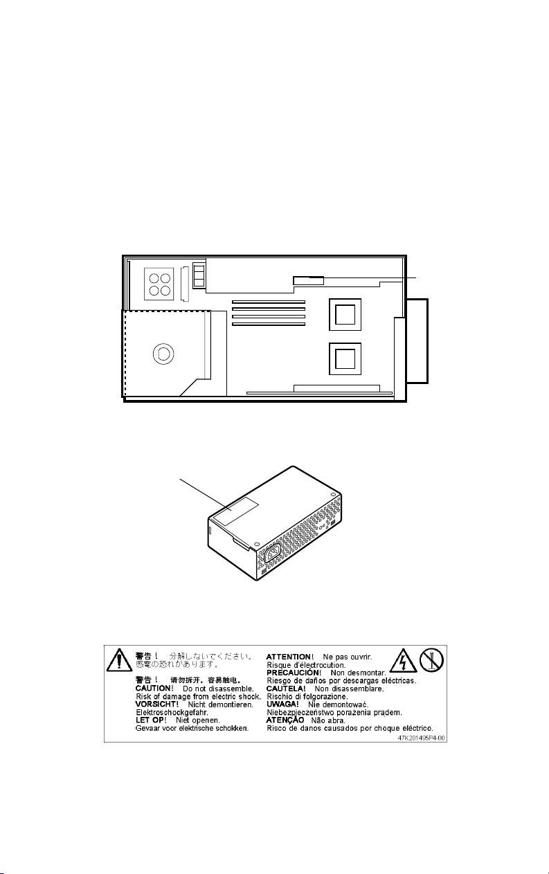
Warning Label
Some warning labels are attached to units of this equipment, as
shown below.
Read these labels carefully for safe use of this equipment:
power supply unit (System Unit)
Label
Label
power supply unit (External Unit)
Page 3
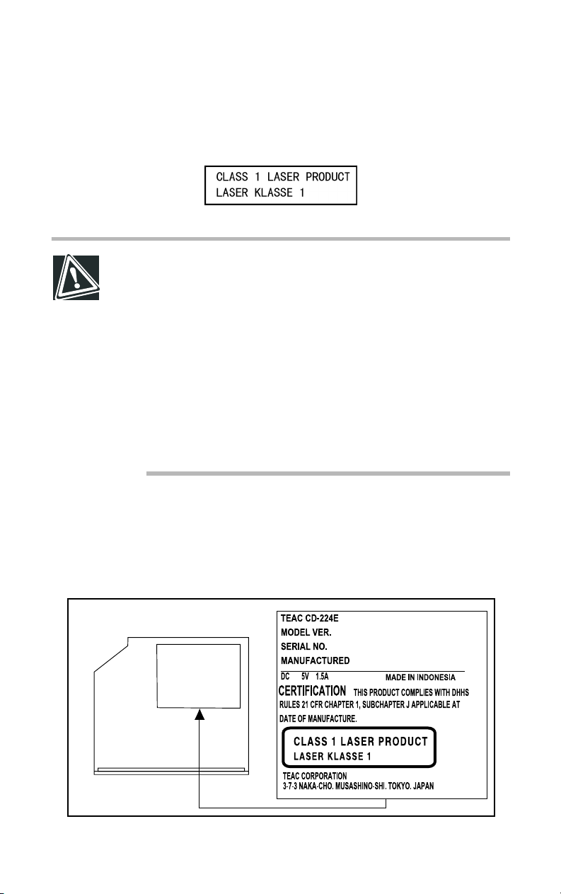
CD-ROM Safety Instruction
CAUTION: This appliance contains a laser system and is
classified as a “CLASS 1 LASER PRODUCT.”
To use this model properly, read the instruction manual
carefully, and keep it for your future reference.
In case of any trouble with this model, please contact your
nearest “AUTHORIZED service station.”
To prevent direct exposure to the laser beam, do not try to
open the enclosure.
Use of controls or adjustments, or performance of procedures other than those specified in the owner’s manual,
may result in hazardous radiation exposure.
Location of the required label
Page 4

Copyright
This guide is copyrighted by Toshiba Corporation with all rights reserved. Under
the copyright laws, this guide cannot be reproduced in any form without the prior
written permission of TOSHIBA. No patent liability is assumed, however, with
respect to the use of the information contained herein.
©December 2002 by Toshiba Corporation All rights reserved.
Page 5

Disclaimer
The information contained in this manual, including but not limited to any
instructions, descriptions and product specifications, is subject to change without
notice.
TOSHIBA CORPORATION (TOSHIBA) PROVIDES NO WARRANTY
WITH REGARD TO THIS MANUAL OR ANY OTHER INFORMATION CONTAINED HEREIN AND HEREBY EXPRESSLY DISCLAIM
ANY IMPLIED WARRANTIES OF MERCHANTABILITY OR FITNESS FOR ANY PARTICULAR PURPOSE WITH REGARD TO ANY
OF THE FOREGOING. TOSHIBA ASSUMES NO LIABILITY FOR
ANY DAMAGES INCURRED DIRECTLY OR INDIRECTLY FROM
ANY TECHNICAL OR TYPOGRAPHICAL ERRORS OR OMISSIONS
CONTAINED HEREIN. IN NO EVENT SHALL TOSHIBA BE LIABLE
FOR ANY INCIDENTAL, CONSEQUENTIAL, SPECIAL, OR EXEMPLARY DAMAGES, WHETHER BASED ON TORT, CONTRACT, OR
OTHERWISE ARISING OUT OF OR IN CONNECTION WITH THIS
MANUAL OR ANY OTHER INFORMATION CONTAINED HEREIN
OR THE USE THEREOF.
Software products that were licensed to you in conjunction with this IA server
product may incorporate or be applying certain modification module(s) (i.e. service pack, security patches, etc.). However, newer version(s) of such modification module(s) may be made available by the licensor of said module(s).
Please install and/or use such newer modification module(s) based on your own
judgment and responsibility.
TOSHIBA MAKES NO REPRESENTATIONS OR WARRANTIES,
EXPRESS OR IMPLIED, AS TO THE PERFORMANCE OF SUCH
NEWER MODIFICATION MODULE(S) (INCLUDING INSTALLATION THEREOF), AND PERFORMANCE OF APPLICATION SOFTWARE BASED ON SUCH NEWER MODIFICATION MODULE(S). IN
NO EVENT WILL TOSHIBA BE LIABLE FOR ANY DIRECT, INDIRECT, INCIDENTAL, CONSEQUENTIAL, SPECIAL OR PUNITIVE
DAMAGES ARISING OUT OF THE USE OF SUCH NEWER MODIFICATION MODULE(S).
Page 6

Trademarks
MAGNIA is a trademark of TOSHIBA Corporation.
Pentium and LANDesk are registered trademarks of Intel Corporation.
PS/2 is a trademark of International Business Machines Corporation.
MS, Microsoft, and its logos MS-DOS, Windows, and Windows NT are registered trademarks or trademarks of Microsoft Corporation.
Linux is a registered trademark or trademark of Mr. Linus Torvald in the USA
and other countries.
Ethernet is a registered trademark of Xerox, Inc.
EZ-SCSI and SCSI Select are registered trademarks of Adaptec, Inc.
MegaRAID is a registered trademark of LSI Logic Corporation.
U.S. Robotics, Sportster, and V. Everything are registered trademarks of 3Com
Corporation or its subsidiaries.
Other product names and trademarks belong to the individual companies
concerned.
Page 7
TOSHIBA
Toshiba declares, that the product: SYU3860*/SYU3869* conforms to the following Standards:
Toshiba erklärt, daβ das Produkt: SYU3860*/SYU3869* folgenden Normen entspricht:
Toshiba déclarent que le produit cité ci-dessocus:
SYU3860*/SYU3869* est conforme aux normes suivantes:
Toshiba declaran que el producto: SYU3860*/SYU3869* cumple los sigulentes estándares:
Toshiba dichiara, che il prodotto: SYU3860*/SYU3869* è conforme alle seguenti norme:
Toshiba intygar att produkten: SYU3860*/SYU3869* överensstämmer med föijande normer:
Supplementary Information: “The product complies with the requirements of the Low Voltage
Directive 73/23/EEC and the EMC Directive 89/336/EEC.”
Weitere Informationen: “Das Produkt entspricht den Anforderungen der Niederspan-
nungs-Richtlinie 73/23/EG und der EMC-Richtlinie 89/336/EG.”
Informations complérnentaires: “Ce produit est conforme aux exigences de la directive sur les
basses tensions 73/23/CEE et de la directive EMC 89/336/CEE.”
Información complementaria: “El Producto cumple los requistos de baja tensión de la Directiva
73/23/CEE y la Directiva EMC 89/336/CEE.”
Ulteriori informazioni: “Il prodotto é conforme ai requisiti della direttiva sulla bassa ten-
sione 73/23/EG e la direttiva EMC 89/336/EG.”
Ytteligare information: “Produkten uppfyller kraven enligt lägspänningsdirektiver
73/23/EEC och EMC-direktiv 89/336/EEC.”
This product is carrying the CE-Mark in accordance with the related European Directives. Responsible for CE-Marking is Toshiba Europe GmbH, Hammfelddamm 8, 41460 Neuss, Germany.
EU Declaration of Conformity
EU Übereinstimmugserklärung
Déclaration de conformité UE
Declaración de conformidad de la UE
Dichiarazione di conformità UE
EU Försäkran om Överensstämmelse
Notice to user of EN55022
!
WARNING: This is a Class A product. In a domestic environment, this product may cause radio interference in
which case the user may be required to take adequate
measures.
Page 8

Introduction
Key features of the MAGNIA Z500
Compact chassis of 2U 1/2 width of 19” rack
!
Installation flexibility (Rack and Desktop)
!
Up to two Xeon processors (2AGHz, 2.40GHz, 2.80GHz)
!
Supports Hyper-Threading function provided by a Xeon
!
processor(*)
One 64bit/133MHz PCI-X slot
!
Main memory expandable to a maximum of 4GB
!
24X-speed CD-ROM drive as standard
!
Up to 120 GB hard disk drive (IDE)
!
IDE RAID as standard (RAID 0 and 1)
!
Hot-swap hard disk drives
!
Ultra 160 SCSI IF (option)
!
2 LAN ports (1000BASE-T) provided as standard, ALB
!
(Adaptive Load Balancing) and AFT (Adapter Fault Tolerance) compatible
ix
Page 9
x
Wireless LAN (IEEE802.11b) card (option) can be mounted
!
Remote management mechanism via network (power ON/
!
OFF, reboot provided as standard)
Server setup assist software “Toshiba Server Setup Tool”
!
Integrated server operation management software HarnessEye/
!
web
Flexibility of system configuration with external units (Exter-
!
nal Hard Drive Unit Z1 and External Device Bay Unit Z1)
* The number of CPUs displayed by the Hyper-Threadind func-
tion in “Control Panel”- “Administrative Tools”- “Computer
Management”- “System Information”- “System Summary” on
Windows 2000 is as twice as the number of mounted CPUs
(1CPU: “2”, 2CPUs: “4”).
This is because that Windows 2000 recognizes one physical
CPU as two logical CPUs. To check the number of mounted
CPUs, use HarnessEye/web.
NOTE: The MAGNIA Z500 meets the FCC regulations for
a Class A digital device, suitable for use in a business
installation. There is a possibility of radio interference when
using the MAGNIA Z500 in a home environment.
About this guide
This guide introduces the features of the MAGNIA Z500 and
explains how to set up, configure, and maintain the server.
Before using the MAGNIA Z500 server, please read through the
guide to gain an overall understanding of operating procedures
and safety precautions.
Page 10
Safety cautions
Before attempting to use your Toshiba MAGNIA Series Server,
all safety instructions must be read carefully and fully understood .
This manual contains the safety instructions that must be observed
in order to avoid potential hazards that could result in personal
injuries or could damage your rack or the units installed in them.
The safety instructions have been classified according to the seriousness of the risk, and the following icons highlight these
instructions as follows:
DANGER: This icon indicates the existence of a hazard
that could result in death or serious bodily injury if the
safety instruction is not observed.
CAUTION: This icon indicates the existence of a hazard
that could result in damage to equipment or property if the
safety instruction is not observed.
xi
WARNING: This icon indicates the existence of a hazard
that could result in bodily injury if the safety instruction is
not observed.
NOTE: This icon indicates information that relates to the
safe operation of the equipment or related items.
When installing any unit or maintaining the system, it is extremely
important that basic safety practices are followed.
Page 11
xii
Other icons used
Additional icons highlight other helpful or educational
information:
TECHNICAL NOTE: This icon provides technical information about the server which, while not essential, may be of
interest to you.
HINT: This icon denotes helpful hints and tips.
DEFINITION: This icon indicates the definition of a term
used in the text.
Other documentation
The server comes with the following documentation:
The MAGNIA™ Z500 User’s Guide ((contains instructions for
!
setting up and optimizing installation of Microsoft®
Windows®2000. This also includes the installation of
Toshiba-authorized option drivers..
Access Point Manual
!
Harness Eye Web Manual
!
Mega Raid Configuration Console Guide.
!
The Safety Instruction Guide for Toshiba Servers contains
!
safety information.
Warranty information Booklet.
!
Read Me First Addendum.
!
Software License Agreement.
!
Page 12

Service options
Toshiba offers a full line of service options built around its warranty programs. See the warranty and service material included
with the server for registration information.
Maintenance contracts
Periodic maintenance and inspection is essential for keeping the
server fully operational and assuring its safe use. Toshiba recommends taking out a maintenance contract for this purpose.
xiii
Page 13

Contents
Chapter 1: Getting Started............................................................................. 2
Checking the items included with the server............................................ 2
Mounting optional internal devices............................................................ 4
Environmental considerations.................................................................... 5
Micro Tower Type/Rack Type............................................................... 5
Micro Tower Type ................................................................................... 7
Rack Type................................................................................................ 8
Power requirements.................................................................................... 9
Front view (with the front panel closed) ................................................. 10
Key lock................................................................................................. 10
Front view (with the front panel opened)................................................ 11
(1) Front panel .......................................................................................11
(2) Operation buttons .......................................................................... 12
(3) System status indicators ............................................................... 15
(4) Card slot .......................................................................................... 17
(5) USB connectors ............................................................................. 17
(6) Device bay ...................................................................................... 17
(7) HDD/LAN status indicators ........................................................... 18
Page 14

xvi
Rear view................................................................................................... 21
(1) AC connector .................................................................................. 21
(2) Security Lock slot ...........................................................................21
(3)Expansion slot................................................................................. 22
(4)LAN status indicators...................................................................... 22
(5)Unit ID indicator............................................................................... 22
I/O connectors...................................................................................... 23
Inside the server........................................................................................ 24
(1) Motherboard................................................................................... 24
(2) SCSI riser card............................................................................... 24
(3) Cooling fans.................................................................................... 25
(4) CPU sockets................................................................................... 25
(5) Memory slots.................................................................................. 25
(6) Expansion slot................................................................................ 25
(7) IDE HDD cage................................................................................ 25
(8) Board for wireless card.................................................................. 25
Connecting peripheral devices................................................................ 25
How to connect peripheral devices ................................................... 25
Connecting the power cable.................................................................... 28
Switching on the server............................................................................ 30
Turning on the server in the usual process....................................... 30
Turning on the server by the “Remote Management” function...... 31
POST (Power On Self-Test).................................................................... 32
Starting up the system.............................................................................. 33
Starting up with the floppy disk........................................................... 33
Starting up by the hard disk drive unit (in the case the OS has been
installed)................................................................................................ 34
Starting up by the CD-ROM............................................................... 35
BIOS setup................................................................................................ 35
Making a floppy disk................................................................................. 36
How to make a backup floppy disk.................................................... 36
Setup of system configuration................................................................. 37
BIOS setup utility.................................................................................. 37
Setup of the time.................................................................................. 37
SCSI utility............................................................................................. 37
IDE RAID Setup utility ......................................................................... 38
Page 15

xvii
Setup of disk array (RAID)....................................................................... 39
Installing software..................................................................................... 40
Switching off the server............................................................................ 41
Normal shutdown ................................................................................ 41
Using the automatic shutdown function............................................ 41
Notes on use of the automatic shutdown function.......................... 43
Abnormal system shutdown .............................................................. 44
Chapter 2: Installing and Removing Hardware......................................... 46
Before starting operation.......................................................................... 46
Before starting operation..................................................................... 47
Installing/removing an optional device.............................................. 50
Removing and replacing the server panels .......................................... 52
Replacing the server panels (for Micro Tower Types)..................... 53
Removing/replacing the server panels (for Rack Types)............... 53
When using a Rack Type................................................................... 54
Memory module........................................................................................ 67
Installing an additional memory module........................................... 69
Removing a memory module............................................................ 72
CPU module.............................................................................................. 73
Installing the CPU module.................................................................. 74
Replacing the CPU module ............................................................... 85
Internal battery........................................................................................... 95
Replacing the internal battery............................................................. 96
Hard Disk Drive (HDD) –IDE HDD–...................................................... 98
Installing the hard disk drive ............................................................... 98
Replacing a hard disk drive during operation................................. 100
Expansion cards..................................................................................... 104
Restrictions on PCI expansion cards.............................................. 104
Installing the expansion card............................................................ 104
Installing the SCSI riser card............................................................ 106
Chapter 3: External Unit Setup................................................................. 114
Types of External Unit............................................................................ 114
Front view of the External Hard Drive Unit Z1 (with the front panel
closed)...................................................................................................... 115
Key lock............................................................................................... 115
Page 16

xviii
Front view of the External Hard Drive Unit Z1 (with the front panel
opened).................................................................................................... 116
(1) Front panel.................................................................................... 116
(2) Operation button........................................................................... 117
(3) System status indicators ............................................................. 118
(4) HDD status indicators.................................................................. 119
Rear view of the External Hard Drive Unit Z1..................................... 121
AC power connector.......................................................................... 121
I/O connectors.................................................................................... 121
(1) External Unit control connector IN/OUT.................................... 121
(2) SCSI connector............................................................................ 122
Installing and Removing Hard Disk Drive (HDD)
-SCSI HDD-............................................................................................. 122
Installing the hard disk drive.............................................................. 122
Replacing a hard disk drive during operation................................. 125
Setup of disk array (RAID)..................................................................... 128
Front view of the External Device Bay Unit Z1 (with the front panel
closed)...................................................................................................... 129
Key lock............................................................................................... 129
Front view of the External Device Bay Unit Z1 (with the front panel
opened).................................................................................................... 130
(1) Front panel.................................................................................... 130
(2) Operation button........................................................................... 131
(3) System status indicators ............................................................. 132
Rear view of the External Device Bay Unit Z1.................................... 133
AC power connector.......................................................................... 133
I/O connectors.................................................................................... 133
(1) External Unit control connector IN/OUT.................................... 133
(2) SCSI connector............................................................................ 134
Installing SCSI device............................................................................. 134
Terminator........................................................................................... 134
SCSI ID............................................................................................... 134
How to Connect External Unit............................................................... 139
Page 17

xix
Chapter 4: System Configuration Setup................................................. 142
BIOS setup utility..................................................................................... 142
Starting the setup utility ..................................................................... 143
Menu screen ...................................................................................... 144
Changing BIOS Settings .................................................................. 145
BIOS Settings..................................................................................... 145
SCSI Utility............................................................................................... 154
Starting the SCSI Utility..................................................................... 154
Menu configuration............................................................................ 155
SCSI Utility Keyboard Commands]................................................. 156
Changing SCSI Device Settings ..................................................... 156
Setting Devices.................................................................................. 156
Configuring MegaRAID IDE.................................................................. 159
Configuring MegaRAID IDE............................................................. 159
Using the MegaRAID IDE Setup Utility........................................... 162
Auto Configure Stripe (F1) ............................................................... 165
Auto Configure Mirror (F2) ............................................................... 165
Create Array (F4)............................................................................... 165
Delete Array (F5) .............................................................................. 168
Restore Old Configuration (F6) ....................................................... 168
Edit Options (F7)................................................................................ 168
Save and Exit (F10) .......................................................................... 169
Chapter 5: Installing Software.................................................................. 172
Windows® 2000 Server........................................................................ 172
Preparing floppy disks....................................................................... 172
Change of the boot priority ............................................................... 173
Selecting the disk driver.................................................................... 173
Installing the Device Driver after installing Windows 2000 Server. 176
Installing the display driver................................................................ 178
Installing the network driver.............................................................. 179
Setting SAF-TE controller................................................................. 179
Procedure after installation of the device driver............................. 181
HarnessEye/web.................................................................................... 182
Installing and operation..................................................................... 182
AFT, ALB and IPSec functions ............................................................. 183
Page 18

xx
What are the AFT, ALB and IPSec functions?............................... 183
When using on Windows 2000:....................................................... 183
Auto-shutdown function......................................................................... 189
Setting the auto-shutdown function................................................. 189
Canceling the auto-shutdown function............................................ 189
Chapter 6: Troubleshooting...................................................................... 192
Troubleshooting...................................................................................... 192
You can hear abnormal noise or smell foul odours, and hear a
continuous buzzer.............................................................................. 192
Nothing happens if you press the power switch. Or, nothing
appears on screen even though you can hear the server
running................................................................................................. 193
Characters are distorted or not displayed properly........................ 194
The system status indicators and disk status indicators turn on
abnormally.......................................................................................... 195
The disk and STS indicators light and flash amber....................... 195
The fault indicator lights amber ........................................................ 195
The FDD indicator does not light ..................................................... 196
An error is displayed during POST operation, or POST stops
midway................................................................................................ 196
Loading of RAID controller BIOS stops midway............................ 196
Cannot install the OS......................................................................... 197
The OS does not boot, or the OS bootup stops midway ............. 198
Windows 2000 is locked or cannot be used .................................. 198
Trouble information or error log still remains in the server monitor
function software and other software .............................................. 199
The power button does not function after abortion........................ 199
The internal clock does not keep precise time............................... 199
Trouble with Application Software......................................................... 199
Remedy When Windows 2000 is Usable........................................... 200
Remedy When Windows 2000 is Unusable....................................... 201
Page 19

xxi
Appendix A: Specifications....................................................................... 204
System Unit........................................................................................ 204
External Hard Drive Unit Z1 ............................................................. 206
External Device Bay Unit Z1............................................................ 207
Appendix B: Interfaces.............................................................................. 210
RGB interface..................................................................................... 210
RGB interface synchronizing signals.............................................. 211
Serial interface.................................................................................... 212
Keyboard/mouse interface............................................................... 213
LAN-1/2 interface............................................................................... 214
USB- interface.................................................................................... 214
Expansion slots (64bit/133MHz PCI-X slot)................................... 215
Appendix C: Switch Setting...................................................................... 220
Hardware setup information............................................................. 220
.............................................................................................................. 221
Appendix D: Unit Logs.............................................................................. 224
Unit logs.............................................................................................. 224
Basic system configuration............................................................... 225
CPUs................................................................................................... 225
Memories............................................................................................ 225
IDE Hard disk drives.......................................................................... 226
SCSI units........................................................................................... 226
Expansion cards................................................................................ 226
Expansion units.................................................................................. 227
Other optional items .......................................................................... 227
Page 20

Chapter
Checking the items included with the server ............................ 2
Mounting optional internal devices ............................................ 4
Environmental considerations ..................................................... 5
Power requirements ...................................................................... 9
Front view (with the front panel closed) .................................. 10
Front view (with the front panel opened) ................................ 11
Rear view ..................................................................................... 21
Inside the server .......................................................................... 24
Connecting peripheral devices .................................................. 25
Connecting the power cable ...................................................... 28
Switching on the server .............................................................. 30
POST (Power On Self-Test) ..................................................... 32
Starting up the system ................................................................ 33
BIOS setup .................................................................................. 35
Making a floppy disk ................................................................. 36
Setup of system configuration .................................................. 37
Setup of disk array (RAID) ....................................................... 39
Installing software ....................................................................... 40
Switching off the server ............................................................. 41
1
Page 21

Getting Started
This chapter describes how to set up the server and to have it ready
for use.
Checking the items included with the server
Check the items in the package according to the accompanying
Read Me First Addendum.
If any of them is missing or damaged, please contact the your
Toshiba dealer as soon as possible.
2
Page 22

Getting Started
Checking the items included with the server
NOTE: The check sheet provides a listing of all standard
accessories and their respective quantities.
If you purchase the server together with an optional internal
device, the optional device will also be incorporated with the
standard accessories listed. However, in such a case it is
possible that the quantities of some accessories, e.g., brackets, do not agree with those specified on the list, this is
because they have already been used to fix the optional internal device.
If in contrast an expansion slot panel etc. has been removed
from the server in order to install an optional device instead,
the expansion slot panel removed comes with the server as
an accessory.
3
Page 23

Getting Started
4
Mounting optional internal devices
Mounting optional internal devices
If you have purchased an optional internal device together with the
server, install it before setting up the server.
See “Installing/removing an optional device” on page 58.
If you find it difficult to install an optional device yourself, always
ask an authorized MAGNIA service provider to do it for you.
Page 24
Environmental considerations
Environmental considerations
Micro Tower Type/Rack Type
Install the server in a clean, dust-free and well-ventilated place.
!
Install the server on a level and steady surface.
!
Never install the server upside down.
!
Ensure the following when installing the server:
!
- Do not exposed to direct sunlight
- Do not install in location susceptible to vibrations or shocks
- Do not install near an apparatus which has strong magnetic
force or produces radio noise. (e.g. radio set, TV set, large
motor or loudspeaker)
- Do not install in location susceptible to large temperature or
humidity changes, or near an air-conditioner air vent, cooling
fan, heater or heat source
Getting Started
5
- Do not install in location where liquids or corrosive chemicals are stored
WARNING: If any foreign matter, including water, has gotten
into the server, perform the shutdown steps immediately, turn
off the power button, and unplug the power cable from the
wall outlet.
Operating the server as it is might cause a fire or an electric
shock. If such trouble occurs, ask an authorized MAGNIA
service provider to inspect your server.
NOTE: Do not turn the server back on until is has completely
dried out.
If the server does not run normally after being turned back on,
contact an authorized MAGNIA service provider.
Page 25

6
Getting Started
Environmental considerations
Only operate the server under the following conditions.
!
- Ambient temperature:
50 to 95°F (10 to 35°C) (Micro Tower Type)
50 to 89°F (10 to 32°C) (Rack Type)
- Ambient humidity: 30 to 80%Rh (No condensation)
NOTE: To avoid condensation when the room temperature is
too high or too low, don’t start your server for about one hour
after the room temperature has fallen within a range of 50 to
95°F (10 to 35°C), or of 50 to 89 °F (10 to 32°C) if your
server is a Rack Type.
Keep the server free from condensation during use and storage.
Page 26
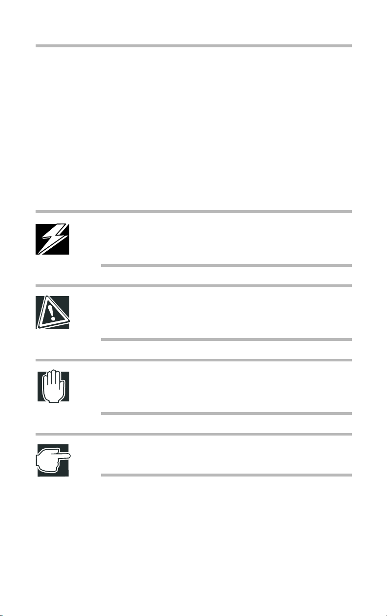
Micro Tower Type
Leave enough space around the server for maintenance and
ventilation.
12 inches
(30cm) or
more
Getting Started
Environmental considerations
8 inches (20cm) or more
7
Minimum clearances required for horizontal installation
12 inches (30cm)
or more
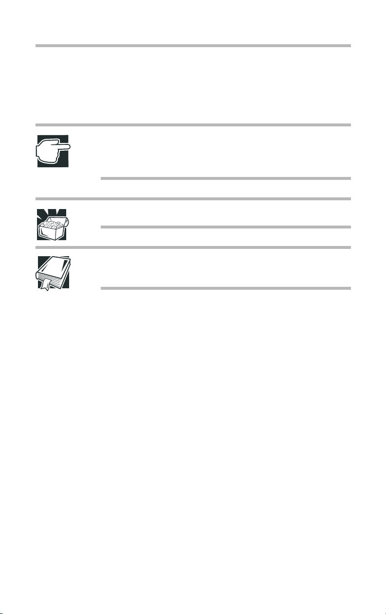
Minimum clearances required for vertical installation
Up to four System Units and External Units can be installed when
stacked horizontally.
Use the stands when you use the server as vertical installation.
8 inches (20cm) or more
stands
Page 27
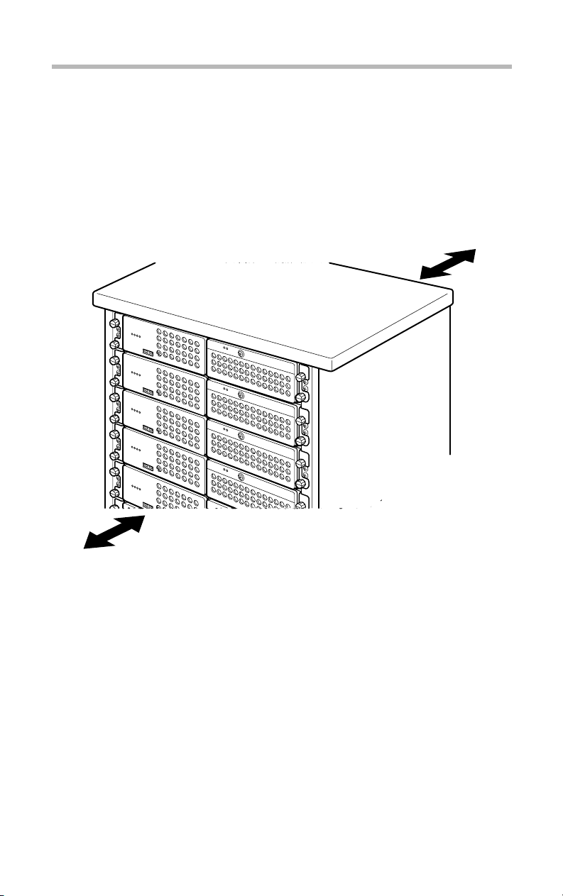
8
Rack Type
Getting Started
Environmental considerations
Use optional Toshiba rack and rack mount kit to install a Rack
!
Type.
Leave a clearance of more than 24 inches (60 cm) before and
!
behind the rack to ensure good ventilation for the server.
24 inches (60cm) or more
24 inches (60cm) or more
Minimum clearances for installation
Page 28
Power requirements
Before plugging the power cable in to a wall outlet (especially if
your server is a Rack Type), ensure the following: make sure that
the capacity of the power supply (current rating of the wall outlet)
and that of the over-current protector (current rating of the circuit
breaker) are correct.
Whenever you have a question about wiring etc., always consult
an authorized MAGNIA service provider.
The maximum power consumption is 300W.
To ensure the server is securely grounded, always use the power
cable supplied with the server.
For wiring in the rack, use an optional AC multi-tap recommended by Toshiba.
WARNING: Do not use any power cable other than the supplied one.
The use of an improper power cable might result in a fire.
Getting Started
Power requirements
9
Do not use any optional part other than the Toshiba genuine
parts or parts recommended by Toshiba.
The use of a parts other than those recommended byToshiba
may result in a fire. For optionally-available parts and
devices, contact an authorized MAGNIA service provider.
NOTE: For both Micro Tower Type and Rack Type, it is recommended to use an uninterruptible power supply (UPS).
Page 29
Getting Started
10
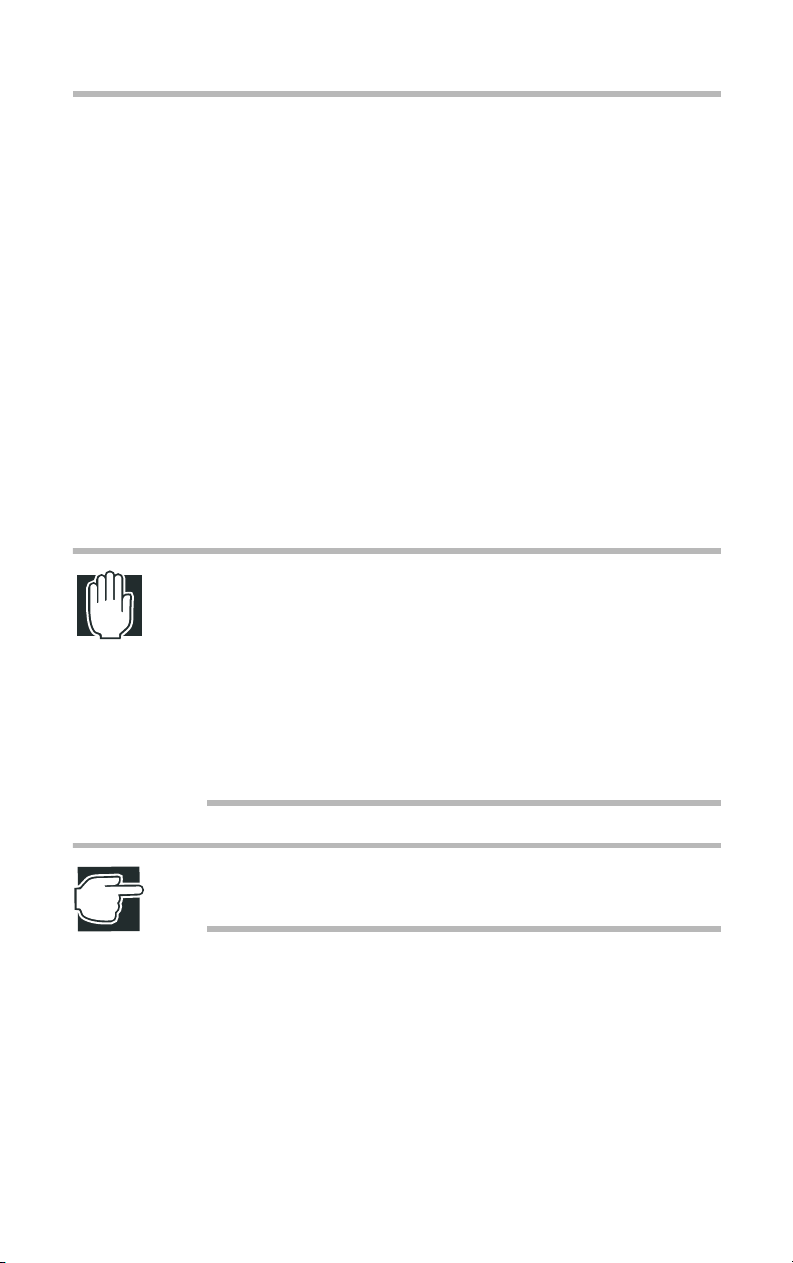
Front view (with the front panel closed)
Front view (with the front panel closed)
Power indicator ( )
Disk indicator ( )
Auto-shutdown indicator ( )
Fault indicator ( )
Key lock
USB connector
Front view with the front panel closed
Key lock
The front panel can be locked in two levels: full access and no
access, which depend on the direction of the keyhole.
Full access
No access
Key lock
Page 30
Getting Started
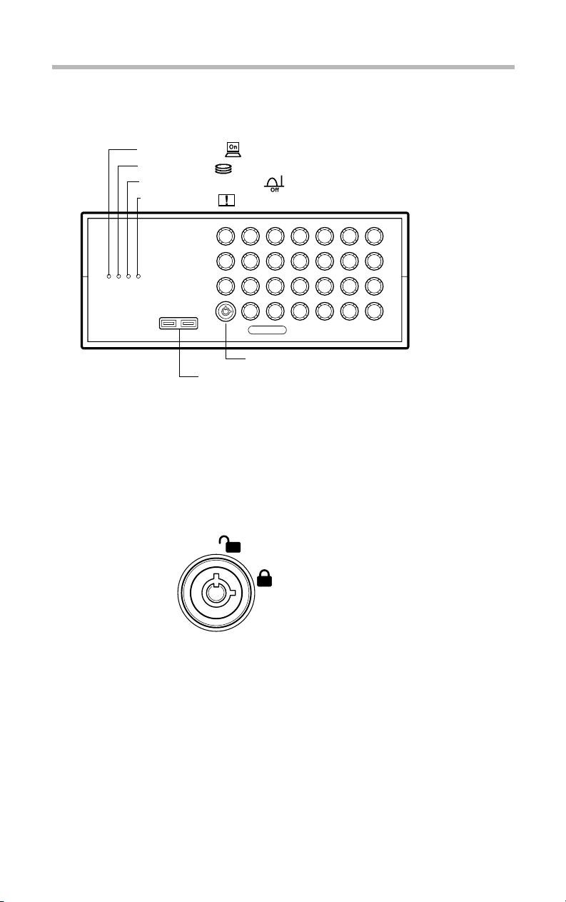
Front view (with the front panel opened)
Front view (with the front panel opened)
(4) System status indicators
(3) Operation buttons
(2) CD-ROM drive
11
(5) Card slot
Front view of the Micro Tower Type
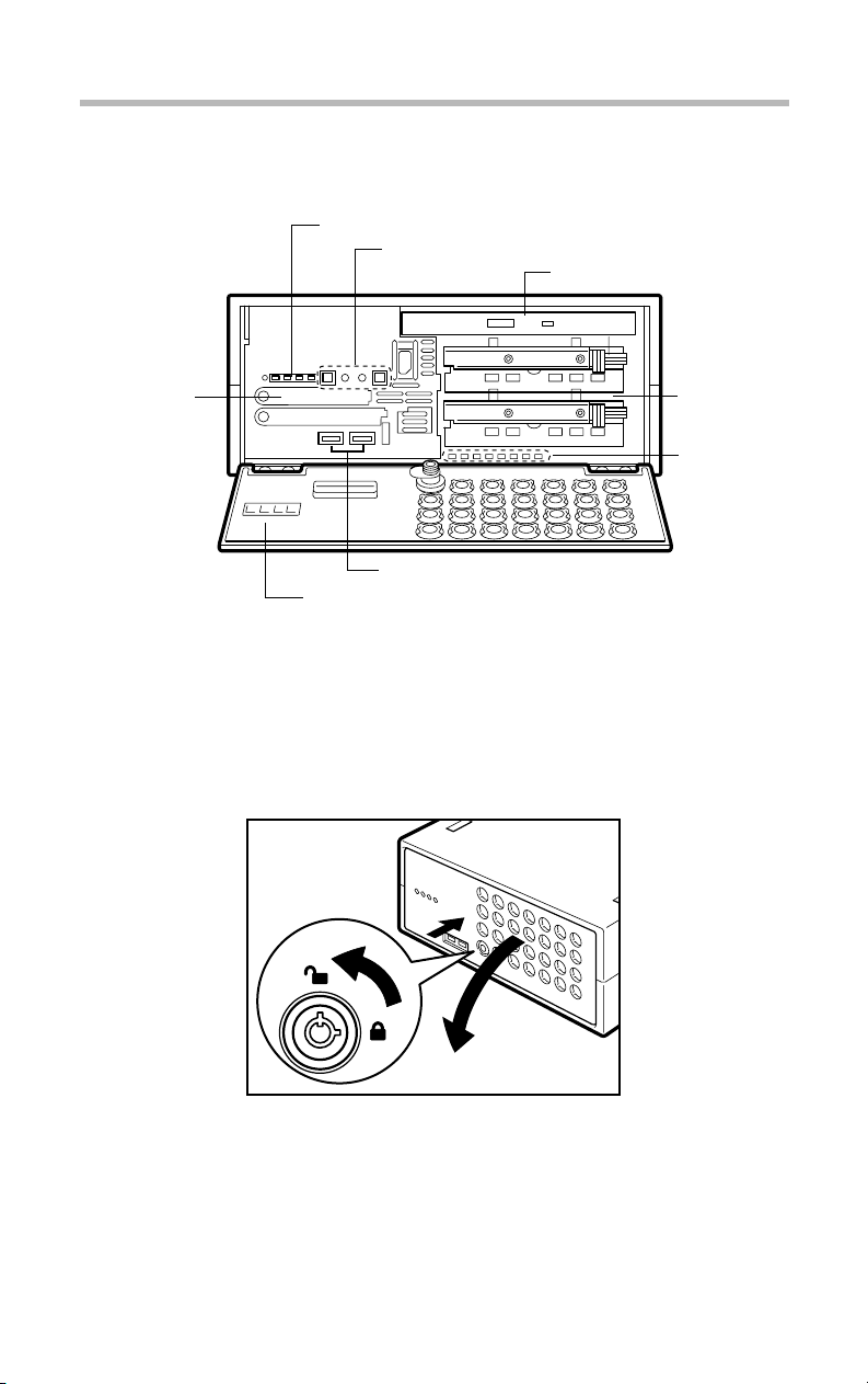
(1) Front panel
The front panel can be opened by releasing the key lock, pushing
its upper center (::) and detached by unhooking its hinges.
(7) Device bay
(8) HDD/LAN
status
indicators
(6) USB connectors
(1) Front panel
Opening the front panel
Page 31

12
Getting Started
Front view (with the front panel opened)
Open the front panel and pull it toward you to remove the front
panel.
Removing the front panel
Hold both the ends (indicated by arrows in the figure) of the front
panel and insert it into the hinges to install.
Attaching the front panel
(2) Operation buttons
The server has 4 operation buttons on the front panel.
Page 32

Front view (with the front panel opened)
Operation buttons
Power/sleep button ( )
Reset button ( )
NMI button ( )
Display change button ( )
NMI
Getting Started
13
Page 33

14
Getting Started
Front view (with the front panel opened)
Power/
sleep
button
Reset
button
NMI
button
Unit ID
button
Press this button to turn on or off the server.
ON... Pressing the button once causes the server
to start up.
OFF... Enabling the auto-shutdown function: If
you hold your finger continuously for four seconds or more and take your finger away, the OS
is shut down and the power supply is turned off.
If you take your finger away within four seconds,
the power is not turned off.
... Disabling the auto-shutdown function: If
you press once, and take your finger away, the
power is turned off.
Sleep... On OSs that support the power save
mode, releasing this button within 4 seconds
switches between the power save mode (sleep
mode, hibernation mode) and the regular
mode.*1
Press this button to reset the server. Use a fine
wire etc. to press this button.
This button is provided exclusively for the autho-
NMI
rized MAGNIA service provider.
Press this button to enable the UNIT ID function.
When this button is pressed for two seconds or
more, the Auto-shutdown/UNIT ID lamp on the
front panel blinks and the UNIT ID lamp on the
back panel lights up. To disable this function,
press this button for 2 seconds or more.
*1: The sleep mode is operational only when an ACPI-supporting OS (operating
system such as Windows 2000) is installed on the system.
See the instruction manual for your OS.
CAUTION: Do not perform a reset that turns the power off
while the FDD indicator, CD-ROM indicator and disk indicator
are lit. You may lose the data.
Page 34

Front view (with the front panel opened)
The way to switch on and off the server varies depending on the
OS installed on it.
See “Switching on the server” on page 30 and “Switching off the
server” on page 41.
(3) System status indicators
This server has 4 operating status indicators on the front panel.
Power indicator ( )
Disk indicator ( )
Auto-shutdown indicator ( )
Fault indicator ( )
Getting Started
15
System status indicators
Indicator Status Meaning
Power Off Out of operation (AC power not supplied)
Lit amber Out of operation (AC power supplied)
Lit green In operation
Disk Off Out of operation
Flashing
green
Built-in disk drive in operation
Page 35

Getting Started
16
Indicator Status Meaning
Auto
Shutdown/
Unit ID
Front view (with the front panel opened)
Off Out of operation.
Lit green Auto Shutdown function is enabled.
Auto Shutdown function is ready to start when power/
sleep switch is turned off.
Lit amber Auto Shutdown function is out of order
- Auto Shutdown is used on Windows 2000 or Linux,
and the Auto Shutdown function is not installed.
- Auto Shutdown is used on Windows 2000 or Linux,
the Auto Shutdown function is installed, and set to Disabled (*1).
- Windows 2000 or Linux is booting.
- An operating system other than Windows 2000 or
Linux is running.
Flashing
amber
Fault Off One of the following modes:
Lit amber - The cooling fan or/and power supply unit or/and disk
*1: Sets the Auto Shutdown function to Disabled/Enabled.
Unit ID function is in operation.
- Out of operation
- The cooling fan, power supply unit and disk are in the
normal state.
is faulty.
See “Auto-shutdown function” on page 197.
NOTE: If any trouble has occurred, contact an authorized
MAGNIA service provider.
Page 36

(4) Card slot
The card slot accepts an optional wireless LAN card.
(5) USB connectors
Used to connect USB devices.
(6) Device bay
The device bay can accommodate up to two hot plug hard disks.
Getting Started
Front view (with the front panel opened)
17
Page 37

Getting Started
18
Front view (with the front panel opened)
(7) HDD/LAN status indicators
When the device bay accommodates hard disk drives, the status of
each hard disk drive is indicated by the PWR indicators and the
STS indicators placed below the device bay.
The network status of the LAN1 and LAN2 connectors are displayed on the ACT indicators and the SPD indicators.
)
(
ACT 1
) (
SPD 1
)
ACT 2
(
)(
SPD 2
HDD 2
HDD 1
PWR 2 ( )
STS 2 ( )
PWR 1 ( )
STS 1 ( )
Indicator Status Meaning
SPD 1
(LAN1)
Off No cable is connected or the server is oper-
ating at 10Mbps.
Lit
The server is operating at 100Mbps.
green
Lit
The server is operating at 1000Mbps.
amber
ACT 1
(LAN1)
Off Link is not established.
Lit
Link is established.
amber
Flashing
It is accessing to the network.
amber
Page 38

Getting Started
Front view (with the front panel opened)
Indicator Status Meaning
SPD 2
(LAN2)
Off No cable is connected or the server is oper-
ating at 10Mbps.
Lit
green
The server is operating at 100Mbps.
19
ACT2
(LAN2)
STS 1
(HDD1)
PWR 1
(HDD1)
STS 2
(HDD2)
Lit
amber
Off Link is not established.
Lit
amber
Flashing
amber
Off No hard disk drive is installed.
Lit green Data is being read or written.
Lit
amber
Flashing
amber
Off No hard disk drive is installed.
Lit green Power is supplied to the hard disk drive.
Off No hard disk drive is installed.
Lit green Data is being read or written.
Lit
amber
The server is operating at 1000Mbps.
Link is established.
It is accessing to the network.
No data is being read or written.
Trouble has occurred.
The disk array is being rebuilt.
No power is supplied to the hard disk
drive.
No data is being read or written.
Trouble has occurred.
Flashing
amber
The disk array is being rebuilt.
Page 39

20
Getting Started
Front view (with the front panel opened)
Indicator Status Meaning
PWR 2
(HDD2)
NOTE: When a STS indicator is lit amber, the corresponding
hard disk drive may be faulty. If it is found to be defective,
replace it. If your system is configured in redundancy
(RAID1), you can replace the faulty drive without interrupting
the system operation.
Shock and vibration might damage hard disk drives, causing
the loss or corruption of the data and programs recorded on
them. So always handle them carefully.
Installing and replacing a hard disk drive requires special
techniques and knowledge. So instead of installing or replacing it yourself, ask an authorized MAGNIA service provider
for assistance.
Off No hard disk drive is installed.
No power is supplied to the hard disk
drive.
Lit green Power is supplied to the hard disk drive.
An error committed during installation or replacement, especially when the system is running, might result in a system
failure and/or the corruption or loss of important data and programs.
Keep hard disk drives free from shock and vibration, especially when they are on. Even if the STS indicator is off, its
magnetic head remains in the data area and, if a shock is
given, it might destruct the data area.
When the server is switched off, the magnetic head of each
hard disk drive automatically retracts. Note that it takes about
30 seconds for a hard disk drive to stop completely.
Page 40

Rear view
(2) S
t
Getting Started
Rear view
21
(3) Expansion slot
ecurity Lock slo
(4) LAN status indicators
Rear view of the server
(1) AC connector
Used to connect the AC power cable.
See “Connecting the power cable” on page 28.
(2) Security Lock slot
It is possible to attach chains, etc. to prevent the server from theft.
onnect the one end to the server and the other end to a fixed object
such as a table, etc.
(1) AC connector
(5) Unit ID indicator
Security Lock slot
Security Lock
slot
Page 41

Getting Started
22
Rear view
(3)Expansion slot
The server has 1 expansion slot for expansion cards: 64 bit/133
MHz PCI-X slot.
(4)LAN status indicators
Activity
Indicator Status Meaning
Link Lit green Connected successfully
Activity Lit green Data being transferred
(5)Unit ID indicator
Indicator Status Meaning
Unit ID Off The Unit ID function is not in operation.
Link
LAN 1 connector
Link
LAN 2 connector
Activity
Off Network cable not connected or incor-
rectly connected
Off No active
Lit blue The Unit ID function is in operation.
Page 42

I/O connectors
Plug the cables of peripheral devices into their respective I/O
ports.
(7) External unit control connector ( )
(3) LAN 1
connector
Ether
(1)
(4) LAN 2
connector
(2)
Ether
I/O connectors
(8) SCSI connector ( )
(1) Mouse connector ( )
(2) Keyboard connector ( )
(6) Serial connector ( )
Getting Started
Rear view
(5) RGB connector ( )
23
(1) Mouse connector ( )
Used to connect the PS/2 mouse.
(2) Keyboard connector ( )
Used to connect the PS/2 keyboard.
(3) LAN 1 connector ( )
1
Used to connect a 1000BASE-T, 100BASE-T or 10BASE-T.
(4) LAN 2 connector ( )
2
Used to connect a 1000BASE-T, 100BASE-T or 10BASE-T.
(5) RGB connector ( )
Used to connect a display.
(6) Serial connector ( )
Used to connect an RS-232C-compliant device.
(7) External unit control connector ( )
Used to connect the external unit.
Page 43

Getting Started
24
Inside the server
(8) SCSI connector ( ) (option)
Used to connect the SCSI riser card.
See “How to connect peripheral devices” on page 25.
Inside the server
(8) Board for wireless card
(4) CPU sockets(5) Memory slots
(3) Cooling fans
Inside the server (Top view)
(1) Motherboard
The main board can contain 2 CPU modules and 4 memory modules at the maximum.
(2) SCSI riser card
The SCSI riser card has 1 PCI-X expansion slot (half length cards
only).
(2) Riser Card / SCSI Riser Card
(6) Expansion slot
(1) Motherboard
(7) IDE HDD Cage
Page 44

(3) Cooling fans
The server contains two cooling fans.
(4) CPU sockets
Used to mount CPU modules.
See “CPU module” on page 81.
(5) Memory slots
Used to mount up to 4 memory modules to expand the server’s
RAM (Random Access Memory).
See “Memory module” on page 75.
(6) Expansion slot
Used to mount expansion cards. A 64 bit/133 MHz PCI-X card of
card length 194 mm or less can be added on to the rise card. The
slot is compliant with PCI 2.2 standard.
Getting Started
Connecting peripheral devices
25
See “Expansion cards” on page 112.
(7) IDE HDD cage
Used to mount 3.5” hard disk (IDE).
(8) Board for wireless card
The board for wireless card can contain 2 wireless LAN cards.
Connecting peripheral devices
How to connect peripheral devices
There are USB connectors for connecting USB devices such as
FDD and so on, on the front of the server. And there are I/O connectors for connecting peripheral devices such as a keyboard,
mouse, display and so on, on the back of the server. Properly connect the devices to the connectors before turning on the server.
Page 45

26
Getting Started
Connecting peripheral devices
Connect peripheral devices to the server, according to the following procedure:
NOTE: USB devices can be connected while the server is
running.
Make sure that all the power buttons of the server and external
1
units are turned off.
If the power cables of the server and external units are con-
2
nected to an AC outlet, pull the plug of the power cable out of
the AC outlet.
Connect each of the peripheral devices to a proper connector
3
on the server with an interface cable.
Insert the connectors to the correct ports on the server.
Use the serial converter cable on the serial interface.
Connecting peripheral devices (Front view)
Page 46

Getting Started
Connecting peripheral devices
27
Connecting peripheral devices (Rear view)
If a connector is provided with screws for securing connection,
4
tighten the screws without fail.
After making sure that all the peripheral units are properly con-
5
nected, plug the power cables of the server and peripheral units
into AC outlets.
WARNING: When connecting optional units, be sure to use
genuine Toshiba parts or those recommended by Toshiba. If
something other is connected to the server, it may cause an
outbreak of fire.
For details of optional parts, contact an authorized MAGNIA
service provider.
Page 47

Getting Started
28
Connecting the power cable
Connecting the power cable
NOTE: Use of an uninterruptible power supply (UPS) is recommended to avoid losing data because of unexpected shutdown or power failure.
After connection of peripheral devices is complete, connect the
power cable to this server following the procedure mentioned
below.
Connect the power cable to the connector on the back of the
1
server.
Connecting the power cable
Plug the power cable into an AC outlet or the power output
2
connector of an uninterruptible power supply (UPS).
Page 48

Getting Started
Connecting the power cable
WARNING: Be sure to use the power cable supplied with the
server. Using another power cable may cause an outbreak of
fire.
Plug the power cable into an AC outlet with a ground line. If
the power cable is plugged into an unspecified AC outlet, it
may cause an outbreak of fire or electric shock.
When disconnecting the power cable from the AC outlet,
don’t pull the cord but hold the plug. If the power cable is
pulled for disconnection, it may cause not only breakdown of
the power cable but an outbreak of fire or electric shock.
When connecting and disconnecting the power cable, hold
the plug without fail.
NOTE: Before plugging the power cable into an AC outlet,
check to see if the AC outlet has a current capacity enough to
cover the whole power consumption of the server system. If
the power consumption exceeds the capacity of the AC outlet, it may cause the equipment to be damaged or to catch
fire.
29
Don’t share the power supply of an AC outlet with any electric
appliance that consumes high electric power or generates
electric noise, such as an air conditioner or photocopier.
Don’t turn the power off during POST, except for some urgent
needs. The power is forcibly turned off by pressing the power/
sleep button for more than 4 seconds.
Page 49

Getting Started
30
Switching on the server
Switching on the server
NOTE: When turning on the server again, turn on the power
button at least 10 seconds after the power button was last
turned off. If the server is switched on again within 10 seconds after it was switched off last, it may cause malfunction of
the server or trouble with it.
When using the server with peripheral devices, connect them
before switching on the server.
Turning on the server in the usual process
Tturn on the server according to the following procedure:
Check to see if all of the peripheral devices such as a display,
1
keyboard, mouse, etc. are correctly connected with the server.
Check to see if the power cables of the System Unit and
2
Exteral Units are connected with AC outlets with the ground
line or an uninterruptible power supply (UPS).
Make sure that the power indicator ( ) lights up in amber.
Turn on the display.
3
Open the front panel.
4
See “Front panel” on page 11
Press the power/sleep button.
5
Make sure that the power indicator ( ) lights up in green.
Page 50

Getting Started
Switching on the server
Pressing the power/sleep button.
31
Turning on the server by the “Remote Management” function
This server has the function that the server can be started up by a
client who is in connection with the network interface.
Installing HarnessEye/web contained in the Toshiba Server Setup
Tool on the client enables packets to be sent from the client to start
up the server.
See “Harness Eye/web User’s Guide” (on your Server Setup
TooL- and Documentation CD-ROM).
Page 51

Getting Started
32
POST (Power On Self-Test)
POST (Power On Self-Test)
When the power/sleep button located on the front panel is pressed
the server is switched on and the “POST (Power On Self-Test)”
(self-diagnosing function) is automatically executed. The motherboard, microprocessor, memory, keyboard and some of the
peripheral devices are automatically checked by the POST. During
the memory test, the storage capacity of the memory being
accessed and tested by the POST is shown on the display.
The following message appears on the display depending on the
setup status of the system.
Press <F2> to enter SETUP
If the <F2> key is pressed following the message, the BIOS setup
utility is started up. If the <F2> key is not pressed, ignoring the
message, the system continues its startup operation.
If an error is detected by the POST, the operator is warned about it
by buzzer sound (beep code).
NOTE: Avoid turning the power off during POST processing.
To forcibly end in an emergency, you can turn the power off
by holding the power/sleep button down for four seconds.
Page 52

Starting up the system
The “Toshiba Server Setup Tool” is to be used for almost all of
setup procedures for this system, such as installing the operating
system (OS), for making backup floppy disks etc.
Besides the hard disk drive and floppy disk drive, the CD-ROM
drive can also be used to start up the server. In that case the
“Startup” CD-ROM must be installed in the CD-ROM drive.
Starting up with the floppy disk
To start up the server from a floppy disk, proceed as follows:
Attach the USB floppy disk drive to the USB port located at
1
the front of the machine
Insert the startup disk in the floppy disk drive.
2
Press the power/sleep button.
3
Getting Started
Starting up the system
33
Page 53

Getting Started
34
Starting up the system
Starting up by the hard disk drive unit (in the case the OS has been installed)
For starting up the server by the hard disk drive unit, proceed as
follows:
Make sure that neither the floppy disk nor CD-ROM that is
1
capable of starting up the server is in either drive unit.
Turn on the power/sleep button.
2
NOTE: The CD-ROM can be ejected from the CD-ROM drive
unit only when the system is turned on. Remove the CDROM from the drive unit before turning off the system without
fail.
If you are in doubt as to whether CD-ROM is set in the CDROM drive unit, check by pressing the eject button of the CDROM drive unit. This procedure must be done while the
power-on self test is being performed after the power/sleep
button is turned on.
If the startup CD-ROM is placed in the CD-ROM drive unit,
the startup operation from the hard disk drive unit will result in
failure, even if the CD-ROM is ejected once the system is has
been switched on.
Page 54

Starting up by the CD-ROM
To start up the server from the CD-ROM, proceed as follows:
Make sure that no floppy disk is placed in the floppy disk
1
drive.
Switch on the power/sleep button.
2
Immediately after switching on the power/sleep button, press
3
the eject button of the CD-ROM drive unit and place the start
up CD-ROM in the drive.
NOTE: The CD-ROM can be ejected from the CD-ROM drive
unit only when the system is on. To start up the server from
the CD-ROM drive unit, it is required to set the startup
CD-ROM in the drive immediately after the power button is
turned on.
If the startup CD-ROM is placed in the drive too late, restart
up the server by simultaneously pressing the following keys:
<Ctrl>+<Alt>+<Delete> .
Once the startup CD-ROM is recognized, the hard disk drive
is disabled from starting up the server, even if the CD-ROM is
ejected.
Getting Started
BIOS setup
35
BIOS setup
Initial system setting on shipment can be changed by the BIOS
setup menu. The BIOS setup can be performed regardless of presence or absence of the operating system. Values entered by the
BIOS setup are written in the CMOS and the flash memory, and
reset values come into effect when the server is restarted. Those
values are used as the reference for execution of the POST.
If the entered values and actual hardware don’t correspond to each
other, an error message appears after the POST is complete. If this
error occurs, change the setting by executing setup operation.
Page 55

Getting Started
36
Making a floppy disk
Making a floppy disk
The server setup support software “Toshiba Server Setup Tool”
has the added function of making system backup floppy disks.
Such disks store important driver data and utilities etc. It is always
recommended to make/store system backup floppy disks for
future use.
How to make a backup floppy disk
To make a system backup floppy disk using the “Toshiba Server
Setup Tool”, proceed as follows (refer also to the on-screen
instructions):
Insert the "Toshiba Server Setup TooL- and Documentation
1
CD-ROM" into the drive, and start the “Toshiba Server Setup
Tool”.
Select “Utility”.
2
Select “Making FD”.
3
Select the name of the floppy disk to create and select “OK”.
4
Place a 1.44MB formatted floppy disk in to the disk drive and
5
select “OK”.
For details on making a floppy disk:
See “Installing software” on page 40.
See “Toshiba Server Setup Tool User’s Guide” (on your Server
Setup TooL- and Documentation CD).
Page 56

Setup of system configuration
Setup of system configuration
If the system is used as it was configured at the factory, it was
properly set up before shipment. However, if something optional
is added to the system after shipment, or it is desired to change the
operating condition properly for use, it is required to set up the system once again.
There are the following utilities prepared for setup of the system
configuration.
See “System Configuration Setup” on page 150.
NOTE: When the system configuration has been changed,
make a note of the configuration information.
BIOS setup utility
Getting Started
37
This utility software is designed to manage (set, store, etc.) the
hardware resources of the server, for example: memory addresses,
I/O ports, DMA channels, and interrupt levels.
Setup of the time
The time on this server can be set by the BIOS setup utility or the
OS you are using.
The RTC has a certain error, and the error is increased cumulatively if it is remained.
To avoid the harmful influence for the operation, adjust the clock
periodically.
SCSI utility
The SCSI utility is to be used to set the SCSI controller of the
SCSI riser card (optional).
Page 57

Getting Started
38
IDE RAID Setup utility
Setup of system configuration
The IDE RAID Setup utility is to be used to set the IDE RAID
controller.
Page 58

Setup of disk array (RAID)
Setup of disk array (RAID)
When an IDE RAID or SCSI RAID controller is additionally
installed in the system after purchase, or if it is built in the server
before delivery, it is required to configure the disk array (RAID).
When “Simple setup” is selected from the “Selection of RAID
configuration” using the Toshiba Server Setup Tool, the RAID is
configured with minimum settings. When “Detailed setup” or “No
setup” is selected, it is still required to configure RAID.
See “MegaRAID Software Guide.” or “MegaRAID IDE Setup”
If the operating system (OS) is installed in the server in which a
SCSI RAID controller or IDE RAID is built in, be sure to install a
Power Console Plus and Service for SCSI RAID controller or
MegaRAID configuration Console for IDE RAID, that is a RAID
monitor and control utility after installation of the OS (for the
Windows 2000).
NOTE: When installing Windows 2000 using the Toshiba
Server Setup Tool, the Power Console Plus and Service can
be automatically installed after installation of the operating
system.
For installation with the Toshiba Server Setup Tool:
See “Toshiba Server Setup Tool User’s Guide” (on your
"Server Setup TooL- and Documentation CD-ROM").
Getting Started
39
Page 59

Getting Started
40
Installing software
Installing software
Once the system is completely set up, install the OS (operating
system), and the accessory software used for the server monitor
function (Integrated server management tool) supplied with the
server and the RAID controller software.
See “User’s Manual for the Operating System” and “Toshiba
Server Setup Tool User’s Guide” (on your "Server Setup TooLand Documentation CD-ROM").
Page 60

Switching off the server
The method for switching off the server varies depending on the
operating system used. Check the operating system and switch the
server off using the normal method or use the automatic shutdown
function.
Every time the server is to be switched off, use only one of the
methods mentioned above. Using both methods simultaneously,
will cause the server to fail during its normal shutdown operation.
Normal shutdown
If no automatic shutdown function is installed in the operating system, switch the server off by using the normal shutdown
procedure as follows.
Prepare the server system for switching it off by the normal
1
method.
For shutting down the operating system,
see “User’s Manual for the Operating System”.
Getting Started
Switching off the server
41
Press the power/sleep button.
2
Using the automatic shutdown function
The automatic shutdown function is only available when the
server runs under the Windows 2000 operating system. If the
power/sleep button is pressed on another operating system, the
server is immediately switched off without the preliminary process necessary for shutdown. In the case the exclusive automatic
shutdown software is not installed in the Windows 2000 operating
system, no automatic shutdown operation is executed and the
server is switched off without the preliminary process as the
power/sleep button is pressed.
When the automatic shutdown function is not used, be sure to execute the preliminary process required for quitting the operating
system before pressing the power/sleep button.
Switch the server off using the automatic shutdown function
according to the following procedure:
Page 61

42
Getting Started
Switching off the server
Execute the specified shut down process for the application
1
software running on the operating system. Be sure to save the
data used on the application software before quitting.
NOTE: As the server is switched off by the automatic shutdown function or ACPI function, the application software currently in use is closed and unsaved data is deleted. The program that is not quit normally will show as a log error or Dr.
Watson error.
If the automatic shutdown application is installed on a Windows 2000-based computer, pressing the power/sleep button
always shuts down the computer, regardless of the setting of
the “Power Options” in “Control Panel”.
Press the power/sleep button to turn off the server.
2
Hold the power/sleep button 4 seconds or more. If the power/
sleep button is released within 4 seconds, the shutdown operation is disturbed in the middle of the process and the server
fails in shutdown.
When the operating system is Windows 2000, the system
becomes ACPI sleep mode.
Make sure that the power indicator ( ) is amber and the
3
server operation is stopped normally. If the server fails in the
normal stop operation, execute the forced stopping operation.
See “Abnormal system shutdown” on page 44.
Page 62

Getting Started
Switching off the server
Notes on use of the automatic shutdown function
Hints on operation of the power/sleep button
If the power/sleep button is used during the operation of the operating system, during the shutdown operation or if the power/sleep
button is operated in a wrong way, it may cause malfunction of the
server.
Follow the instructions stated below to ensure steady operation of
the system:
When starting up Windows 2000, do not operate the power/
!
sleep button until the log-on dialog “Welcome” appears on the
screen following the “Selection of operating system” menu.
After the shutdown operation starts, do not operate the power/
!
sleep button until the “It is now safe to turn off your computer”
dialog appears on the screen.
After the “Restart” command is selected, do not operate the
!
power/sleep button.
43
Do not press the power/sleep button again without allowing
!
some time to pass.
The application in operation
An application in operation is forcedly closed by the shutdown
operation with the power/sleep button. When shutting down the
server in this way, the data in use will not be saved after shutdown.
Load to the system
If the server is shut down by the power/sleep button operation
when the system is heavily loaded, the shutdown operation does
not start immediately after the power/sleep button is released. The
waiting time depends on the degree of the system load. In normal
circumstances this takes about 30 seconds to 1 minute to start the
shutdown operation. In this case, wait a while.
Page 63

Getting Started
44
Switching off the server
Abnormal system shutdown
If the server is not shutdown using the normal method, the system
can be forcibly stopped. However, this operation deletes unsaved
data.
To shut down the system forcibly, press the reset button.
NOTE: If the server was forcibly shutdown, unplug the power
cable from the AC outlet once and plug it in again.
Page 64

Chapter
Before starting operation ............................................................ 46
Removing and replacing the server panels .............................. 52
Memory module ......................................................................... 67
CPU module ................................................................................ 73
Internal battery ............................................................................ 95
Hard Disk Drive (HDD) –IDE HDD– .................................... 98
Expansion cards ........................................................................ 104
2
Page 65

Installing and Removing Hardware
This chapter explains the different methods used to install and
remove optional devices.
Before starting operation
Install optional devices before setting up the server.
46
Page 66

Before starting operation
WARNING: When installing an optional device, be sure to
use genuine Toshiba parts or those recommended by
To s h i b a .
If any other device is used, it may result in a fire hazard.
For more information about optional devices, consult an
authorized MAGNIA service provider.
Do not touch any part irrelevant to the installation work.
The server contains many high-tension parts, which if
touched may cause an electric shock.
While carrying out installation work on the peripheral unit,
take extra care not to drop any removed screws into the
equipment. During installation always follow the instructions.
Tightly fasten every screw. If a screw drops inside the equipment, it may result in a fire hazard.
Installing and Removing Hardware
Before starting operation
47
CAUTION: When installing/removing an optional devices, it is
recommended to wear globes, due to the sharp-edges
located inside of the server.
NOTE: When installing an optional device, carefully follow the
instructions according to the optional device.
Before installing or removing an optional device, always disconnect the power cable from the server.
Before installing or removing optional devices carefully read
the instructions that came with the device.
When installing/removing components, always work in an
environment which has low humidity, minimal dust, and no
direct sunshine.
Page 67

48
Installing and Removing Hardware
Before starting operation
The installation or removal of an optional device should be
carried out at ambient temperatures of 50 to 95°F (10 to
35°C) for Micro Tower Types, or 50 to 89°F (10 to 32°C) for
Rack Types, and at ambient humidity of 30 to 80%. Avoid a
place where the temperature may change sharply because it
may cause condensation inside the equipment.
Don't install/remove an optional device in a static environment (e.g. on a carpet). Electronic parts easily become defective if they are exposed to electrostatic discharge.
Proceed with the installing/removing process in the correct
order.
Different types of screws are used or to be used.
When the system falls into malfunction or failure, consult our
authorized MAGNIA service provider.
After installing/removing components, replace the server panels before switching the server back on.
When tightening a screw, always use the correct fitting screwdriver. An incorrect screwdriver may damage the screw head.
Screw head and screwdriver
You may have to remove cable (s), when installing optional
devices. In this case, check the relative position between the
unit and cables before disconnecting the cables for reference.
Page 68

Installing and Removing Hardware
Before starting operation
When connecting a cable to the server, pay careful attention
to the shape of the connector. If a incorrect connector is forcibly connected, it may bend or damage the connector pins. If
the cable connector has thumb screws for fastening, tighten
them to secure the connection.
Before installing or removing options, touch a part of the
server frame to discharge static electricity.
Carefully handle options whose boards are not covered such
as expansion cards because they are easily affected by static
electricity. When holding an option whose board is exposed,
hold it on the edges carefully.
After taking a device out of the antistatic package, put it horizontally with the components side up on a grounded plane
free from static electricity. After taking out a device, keep the
antistatic packing case for future use. Don't slide the server
for relocation.
The user is not permitted to remove the server from the rack.
If it is hard to install/remove an optional device as the server
is mounted on the rack, ask an authorized MAGNIA service
provider to do the work.
49
Special knowledge and technique are required for installing
an optional device to the server of the Rack Type. If you have
no experience in installing an optional device in the Rack
Type or you consider the task difficult, consult an authorized
MAGNIA service provider about installation.
Page 69

Installing and Removing Hardware
50
Before starting operation
Installing/removing an optional device
WARNING: When installing a peripheral unit, don't open any
part other than those specified by the instructions.
If an irrelevant part is opened, it may cause an electric shock.
Install or remove an optional device following the procedure mentioned below:
Carefully read the precautions mentioned in this chapter
1
(Before starting operation) and check all the items.
Switch off all the peripheral units connected with the server.
2
If the server is running, shut it down and switch off the power.
3
Unplug the power cable of the server from the AC outlet or
4
UPS (uninterruptible power supply), and disconnect all cables
from connectors on the back of the server.
NOTE: Before starting the job, shutdown the server, switch off
the power and disconnect the power cable from the power
supply.
If an optional device is installed when the server is on, it may
cause failure of the server and the option.
Remove the server panels from the server.
5
In case of the Rack Type, pull the server out of the rack before
removing the panels.
See “Removing and replacing the server panels” on page 52.
Install or remove an optional device.
6
Ensure that there is neither tool nor dead part remaining inside
7
the server.
Page 70

Installing and Removing Hardware
Before starting operation
Attach the server panels to the server.
8
In case of the Rack Type, fit the panels to the server before
mounting it on the rack.
Connect the peripheral units and switch them on.
9
Plug the server's power cable connector into an AC outlet (or
10
UPS) and then switch on the server.
Some optional devices need to be setup with jumper switches
and DIP switches.
See “BIOS setup utility” on page 45.
51
Page 71

Installing and Removing Hardware
52
Removing and replacing the server panels
Removing and replacing the server panels
To mount optional devices inside the server, you need to remove
the server panels depending on the option you are mounting.
CAUTION: When sliding a server panel, be careful not to
catch your finger between it and the server. The panel might
cause injury. When removing or installing the server panel,
turn off the power and unplug the power cable connector in
advance. Otherwise, you might get an electric shock.
Removing the server panels (for Micro Tower Types)
Follow these steps to remove the server panels:
Shut down the server and turn off the power if it is in opera-
1
tion.
Unplug the power cable.
2
Remove one screw and slide the outer cover (upper) to the rear
3
of the server.
Removing the outer cover (upper)
Page 72

Installing and Removing Hardware
Removing and replacing the server panels
Open the front panel.
4
See “Front panel” on page 11
Slide the top panel stopper to the left.
5
Slide the top panel to the front of the server and remove it.
6
Removing the top panel
53
Replacing the server panels (for Micro Tower Types)
Follow these steps to replace the server panels:
Replace the top panel to the server carefully so that it does not
1
catch any cable.
Slide the top panel stopper to the right.
2
Attach the outer cover (upper) and fix them together by one
3
screw.
Close the front panel.
4
Plug the power cable.
5
Removing/replacing the server panels (for Rack Types)
Remove/replace the server panels after sliding the server out of the
rack.
The outer cover is not provided on Rack Types.
See “Sliding the server into or out of the rack” on page 60.
Page 73

Installing and Removing Hardware
54
Removing and replacing the server panels
When using a Rack Type
Rack assembly procedure
Quantity check
Rack Mount Tray
No. Name Q’ty
1 Base Assy 1
2Rail R 2
3 Stopper(L) 1
4 Stopper(R) 1
5Rail F WD(L) 1
6Rail F WD(R) 1
7PIN CATCH 2
8 FLAT SCREW (GRIP) 4
9 Screw(M5) 8
10 Screw(M6) 8
Parts provided with the System Unit or External Unit
11 Front Bracket(L) 1
12 Front Bracket(R) 1
13 GUIDE PIN(M4) 1
14 SPRING WASHER 1
15 WASHER 1
16 FLAT SCREW(GRIP) 5
17 RACK BRACKET 1
18 SCREW(M3) 2
Page 74

Installing and Removing Hardware
Removing and replacing the server panels
Parts provided with the rack blank module
19 BLANK BRACKET 1
20 FRONT BRACKET 1
21 FLAT SCREW(GRIP) 3
Decide on where to assemble the server.
1
Installation
position
Screw (M6)
temporary
fastening
positions
1u
1u
55
Decide on where to assemble the server
Page 75

56
Installing and Removing Hardware
Removing and replacing the server panels
Temporarily fasten Rail R to the posts on the left and right of
2
the rack rear, and Rail F (L) and Rail F (R) to the posts on the
left and right at the front with Screws (M6).
Rail R
Rail F WD (L)
Screws (M6)
Temporarily fastening the Rails
Fix Rail R on the left and right, Rail F (L) and Rail F (R) with
3
two Screws (M5).
Fixing Rail F and Rail R
Screws (M5)
Page 76

Installing and Removing Hardware
Removing and replacing the server panels
Attach the Pin Catch on the Base Assembly with two flat
4
screws (M3).
Pin Catch
Tray Base
Flat screws (M3)
Attaching the Pin Catch
Insert the Base Assembly into the Rail.
5
57
Inserting the Base Assembly
Page 77

58
Installing and Removing Hardware
Removing and replacing the server panels
Attach the Stopper (L) and Stopper (R) on the Base Assembly
6
and fix them with two screws (M5).
Stopper (L)
Screws (M5)
Stopper (R))
Attaching the Stoppers
Fix the Base Assembly to the rack with the claw screws on the
7
front.
Claw screw
Fixing the Base Assembly
Page 78

Installing and Removing Hardware
Removing and replacing the server panels
Tighten the eight screws temporarily fastened in step 2.
8
Be sure to tighten the screw. If the screw gets loose, the tray
base or other parts may drop.
Fixing Rails
59
Page 79

60
Installing and Removing Hardware
Removing and replacing the server panels
Sliding the server into or out of the rack
For installing the server to the Rack Type, follow the instructions
mentioned.
WARNING: Don't slide more than two Rack Mount Trays, out
of the rack at the same time. If two or more units are pulled
out of the rack, the rack may become unstable and topple
down.
Don't put any weight on the server that is pulled out of the
rack and don't apply an excessive load to it continuously
because a load may cause the rail to be damaged or the rack
to be unstable. If the rack topples, neighboring persons may
be injured.
For working on the higher part of the rack, don't put a ladder
directly on the rack or the server to prevent the rail, rack and
server from getting damaged or unstable. If the rack topples,
neighboring persons may be injured.
For working on the higher part of the rack, don't climb up on a
chair with casters or the like, because it is unstable.
When turning the claw screws of the Rack Mount Tray,
remove the front panel because you may catch your fingers.
NOTE: Before sliding the server out of the rack, make certain
that no cable connected to its back disturbs the sliding job.
To continue the installing/removing job as the server is slid
out of the rack, slide the server frontward until it is secured by
the lock on the rail.
If another system or an external unit is installed in the rack
besides the server, be careful not to touch the eject lever of
the hard disk drive mounted in another system or the power
button.
Page 80

Installing and Removing Hardware
Removing and replacing the server panels
Sliding the server (Rack Type) into the rack
Attach Washer, Spring Washer and Guide Pin (M6) on the
1
back.
Washer
Spring
Washer
Guide Pin
Attaching the Guide Pin
61
Attach the Front Bracket (L) or Front Bracket (R) to the server
2
bay with Screws (M3).
Screws (M3)
Front Bracket
Attaching the Front Bracket
When you insert the server bay into the right of the rack, attach
Front Bracket (R).
Page 81

62
Installing and Removing Hardware
Removing and replacing the server panels
Place the server bay on the Base Assembly and insert.
3
Inserting the server bay
Remove the Front Panel and loosen the claw screw to draw out
4
the Base Assembly by about 100 mm.
Claw screw
Drawing out the Base Assembly
Page 82

Installing and Removing Hardware
Removing and replacing the server panels
When adding a server or installing a Blank Bracket, mount the
5
Front Bracket on the server or Blank Bracket with two flat
screws (M3) and mount it on the Base Assembly and secure
the Rack Bracket with two screws (M3).
Front Bracket
Rack Bracket
Blank Bracket
Screw (M3)
Fixing the Blank Bracket
When installing an External Unit additionally, secure the
External Unit to the server with a flat screw (M3).
Flat screw (M3)
63
Flat screw (M3)
Fixing the Server Housing
When installing two External Units, or External Unit and Blank Bracket, follow the procedure above.
Page 83

64
Installing and Removing Hardware
Removing and replacing the server panels
Insert the entire Base Assembly into the rack.
6
Inserting the entire Base Assembly
Fix the housing on the left and right with the claw screws of
7
Front Bracket (L) and Front Bracket (R), and attach the front
panel.
Claw screw
Fixing the housing on the left and right
Connect the cables disconnected.
8
Sliding the server (Rack Type) out of the rack
Slide the server out of the rack in the procedure described below,
while referring to “Before starting operation” on page 46.
If the server is running, shut it down and turn off the power.
1
Switch off all the peripheral units connected with the server.
2
Page 84

Installing and Removing Hardware
Removing and replacing the server panels
Unplug the power cable of the server from the AC outlet or
3
UPS (uninterruptible power supply).
Unplug all the cables from the server.
4
Remove the front panel and loosen the four claw screws which
5
fix the Base Assembly and draw out the Base Assembly.
Claw screw
Drawing out the Base Assembly
65
When Removing two servers, or a server and a Blank Bracket,
6
remove two screws (M3) fixing the Rack Bracket and remove
it.
Front Bracket
Rack Bracket
Blank Bracket
Screw (M3)
Removing the Rack Bracket
When removing a server and an External Unit, remove the
flat screw (M3) fixing the Base Assembly.
Flat screw (M3)
Page 85

66
Installing and Removing Hardware
Removing and replacing the server panels
Flat screw (M3)
Removing the screw
Slide the server out of the rack.
7
Page 86

Memory module
Your server can accommodate a maximum of four 128MB, 256
MB, 512MB or 1GB DIMMs (Dual In-line Memory Modules)
with the ECC (Error Correction Control), which operate at a system bus clock frequency of 200 MHz.
See “Specifications” on page 252.
The memory can be expanded to a maximum of 4GB by installing
additional memory modules with up to two different capacities.
When installing additional memory modules, add two modules
with same capacities at a time.
The memory controller is conformable to the DDR SDRAM.
When installing additional memory modules, start from the slot
1A and 1B first, the slot 2A and slot 2B last.
When installing memory modules with different capacities, insert
them in the slots 1A/1B to 2A/2B in order of increasing capacity,
that is, the memory module with the smallest capacity in the slot
1A and 1B.
Installing and Removing Hardware
Memory module
67
Page 87

68
Installing and Removing Hardware
Memory module
Slot1A Slot1B Slot2A Slot2B Total
1024 1024 1024 1024 4096
512 512 1024 1024 3072
256 256 1024 1024 2560
128 128 1024 1024 2304
1024 1024 2048
512 512 512 512 2048
256 256 512 512 1536
128 128 512 512 1380
512 512 1024
256 256 256 256 1024
128 128 256 256 768
256 256 512
128 128 128 128 512
128 128 256
UNIT:MB
Page 88

Installing and Removing Hardware
Memory module
Memory slot 1A
Memory slot 1B
Memory slot 2A
Memory slot 2B
Memory slots (Top view)
WARNING: When installing a peripheral unit, don't open any
part other than those specified by the instructions. Touching
unspecified parts may cause an electric shock.
CAUTION: Don't install or remove additional memory modules just after the server is switched off to avoid burning the
hand with the extension memory sockets and their peripheries that are heated during operation.
69
Installing an additional memory module
NOTE: Since the extension memory module is a precise
electronic device, it may be seriously damaged by static electricity. Before installing an additional memory module, be sure
to discharge static electricity from your body by touching a
metallic thing at hand, because the human body is always
charged with a small amount of electricity.
Before installing an additional memory module, carefully read
“Before starting operation” on page 46 and proceed to the job following procedure mentioned below:
Page 89

70
Installing and Removing Hardware
Memory module
If the server is in operation, shut it down first and cut off the
1
power supply to it.
Unplug the power cable from the AC outlet.
2
NOTE: Installing a memory module while the server is still
energized could cause damage to the server or the memory
module
Remove the server panels from the server.
3
See “Removing and replacing the server panels” on page 52.
Extend the hooks on both sides of the memory slot outwards.
4
Extending the hooks
Page 90

Installing and Removing Hardware
Memory module
Insert the memory module into the proper memory slot, paying
5
heed to the position of each notch on the memory module.
Insert the memory module until it is locked by the hooks on
both sides.
Installing a memory module
Attach the server panels.
6
71
Connect the power cable of the server to the power supply and
7
switch on the server.
NOTE: Don't hold a memory module by the part of the connecting terminal. If the part of the connecting terminal is
touched by hand, it may cause the memory module to have
poor contacts.
Be careful not to insert an extension memory module with an
incorrect orientation. Improper installation of a memory module may cause damage to the memory module or the memory slot.
Page 91

Installing and Removing Hardware
72
Memory module
Removing a memory module
Before removing a memory module, carefully read “Before starting operation” on page 46 and proceed to the job following the
procedure mentioned below:
If the server is in operation, shut it down and switch off power.
1
Unplug the power cable from the AC outlet.
2
NOTE: Removing a memory module while the server is still
on could cause damage to the server and/or the memory
module.
Remove the server panels from the server.
3
See “Removing and replacing the server panels” on page 52.
Extend the hooks on both sides of the memory slot outwards
4
and remove the memory module out of the slot.
When the hooks of the memory slot are extended outwards,
the memory module occasionally springs out of the slot. Be
sure to hold the memory module by hand through the removing work.
Removing a memory module
Fit the server panels to the server.
5
Page 92

Connect the power cable of the server to the power supply and
6
switch on the server
CPU module
The server is classified into 3 models with different CPU clock
speeds (2AGHz, 2.40GHz, 2.80GHz). If two processors are
installed in your server, the server is transformed into an upgraded
version (maximum of two CPUs). Please note that only CPUs
with the same clock speed can be installed together. There is a
socket (No. 2 socket) for installing an expansion CPU.
To install a CPU with a different processing speed, it is necessary
to remove and replace all current CPUs with others with the same
processing speed.
Installing and Removing Hardware
CPU module
73
CPU socket (Top view)
WARNING: When installing a peripheral unit, don't open any
part other than those specified by the instructions. If an
unspecified part is opened, it may cause an electric shock.
CPU socket 1
CPU socket 2
Page 93

Installing and Removing Hardware
74
CPU module
Installing the CPU module
NOTE: The CPU module may be fatally damaged by static
electricity because it consists of precise electronic parts. The
human body contains static electricity. Therefore, discharge
the static electricity before installing the CPU module. Static
electricity can be discharged by touching a nearby metallic
object with your fingers.
Install the CPU module in the procedure described below, while
referring to “Before starting operation” on page 46:
If the server is running, shut it down and turn off the power.
1
Unplug the power cable.
2
NOTE: Installing the CPU module while the power is on could
cause damage to the server or CPU module.
Remove the server panels.
3
See “Removing and replacing the server panels” on page 52.
CAUTION: Do not extend or replace the CPU module immediately after the power is turned off. This may cause burns
because the CPU generates heat in its periphery.
Page 94

Installing and Removing Hardware
CPU module
Remove one screw and the PCI slot cover from the PCI
4
bracket.
Removing the PCI slot cover
Remove one screw that fixes the riser card and fan duct 2 and
5
then pull the lever to remove the riser card.
75
Removing the riser card
NOTE: The riser card may be damaged by contacting with a
fan duct. Be careful to remove and insert the riser card.
Page 95

76
Installing and Removing Hardware
CPU module
Remove the fan duct 2.
6
Removing the fan duct 2
Disconnect the DC cable from the connector.
7
Disconnecting the DC cable
Page 96

Installing and Removing Hardware
Remove one screw and the fan duct 1.
8
Removing the fan duct 1
Remove two screws and the CPU blank.
9
CPU module
77
Removing the CPU blank
Page 97

78
Installing and Removing Hardware
CPU module
Raise the lock lever of the expansion CPU socket.
10
Raising the lock lever
Align correctly the mark of CPU module with the mark of
11
socket and insert the CPU module as far as it will go.
Inserting the CPU module
NOTE: A standard CPU module is installed in the socket 1.
To extend the CPU module, install it in the socket 2.
Page 98

Installing and Removing Hardware
CPU module
Push down the lock lever of the socket until it is hooked
12
securely.
Pushing down the lock lever
Attach the CPU spacer.
13
79
Attaching the CPU spacer
Detach the cover on the contact surface between the heat sink
14
and the CPU module.
Page 99

80
Installing and Removing Hardware
CPU module
Lightly push the heat sink in the direction of the socket, and fix
15
it with four screws.
Attaching the heat sink
Fixing the screws
NOTE: Do not push the fin section of heat sink of the CPU
module. This may cause the deformation of the heat sink.
Push the CPU module until both ends of it become uniformly
horizontal on the right and left and confirm that it was inserted
completely.
Page 100

Installing and Removing Hardware
CPU module
Attach the fan duct 1 and fix it with one screw.
16
Attaching the fan duct 1
Connect the DC cable into the connector.
17
81
Connecting the DC cable
 Loading...