

Page 1

MAGNIA
Software Access Point
User’s Guide
V3.0
Page 2

……………………………………………………………………………………………………
1. No part of this document may be transcribed or reproduced without the express
permission of the publisher.
2. The contents of this document may be revised without prior notice.
3. Every possible effort was made to verify the contents of this document. However, should
you find any mistakes, please notify the publisher.
4. When using this function, take adequate security precautions. We cannot be held liable for
data leaks due to wireless LANs.
5. Notwithstanding item 4 above, the publisher assumes no responsibility for any problems
arising from the use of this document.
……………………………………………………………………………………………………
ii
Page 3

Important Warnings
(*1)
This document contains important information to be observed to prevent damage to users and
bystanders or their property and to use the purchased product safely. The alert messages and
symbols used in this document are shown below with their meanings. Please read them
carefully before proceeding to the text.
! Warnings
Indication Meaning
CAUTION
*1 Personal injury indicates a wound, burn, or electric shock, which does not require hospitalization
or repeated hospital visits for treatment.
*2 Physical damage indicates extensive damage to buildings, household goods, or domestic animals,
pets.
! Symbols
Symbols
This message indicates a potentially hazardous situation that could result in personal injury
or physical damage (*2) if the user does not perform the procedure correctly.
Meaning
Indicates prohibited actions..
The concrete prohibited items are shown by illustrations or messages in or near
the symbol.
Indicates things that are must be done.
The specific required items are shown by illustrations or messages in or near the
symbol.
Indicates cautions.
The specific caution items are shown by illustrations or messages in or near the
symbol.
Notes on Use
! Program and data protection
¤ Back up important programs and data regularly to prevent loss of programs and data.
¤ To store data, observe the following:
· Do not turn off the power while the system is running.
· When initializing a storage media such as a floppy disk or magnetic tape, be sure to check in
advance that no important program or data is stored on it.
· While a storage device such as the floppy disk drive or magnetic tape unit is accessing a storage
medium, do not remove the medium.
iii
Page 4

Preface
This manual describes how to install and operate the MAGNIA Software Access Point.
This manual consists of the following four chapters:
Chapter 1 Outline of Software Access Point
Chapter 2 Installation Procedure
Chapter 3 Utilities
Chapter 4 802.1X Function
Appendixes
For the latest information about this manual, read the readme.txt file.
……Trademarks………………………………………………………………………………………
· Microsoft, Windows and Windows NT are registered trademarks of Microsoft
Corporation in the United States and other coun tries.
· Linux is a registered trademark of Mr. Linus Torvalds in the United States and other
countries.
· Intel is a registered trademark of Intel Corporation.
· Product names appearing in this document may be used as trademarks of individual
companies.
……………………………………………………………………………………………………………………
iv
Page 5

Contents
Applicable Versions and Technical Revisions
Notations Used in This Document
CHAPTER1 OUTLINE OF SOFTWARE ACCESS POINT
1.1 Outline...............................................................................................................................................2
1.2 Operating Environment.....................................................................................................................3
1.3 Configuration.....................................................................................................................................4
1.3.1 Consisting of only wireless LAN.............................................................................................4
1.3.2 Consisting of Wireless and Wired LANs ................................................................................5
1.3.3 Consisting of multiple access points .....................................................................................6
CHAPTER2 INSTALLATION PROCEDUR................................................................................................ 7
2.1 Software Access Point......................................................................................................................8
2.1.1 Installing the Software Access Point......................................................................................8
2.1.2 Uninstalling the Software Access Point...............................................................................18
2.1.3 Upgrading the Software Access Point.................................................................................18
2.2 Access Point Configuration Utility ..................................................................................................20
2.2.1 Installing Access Point Configuration Utility........................................................................20
2.2.2 Uninstalling the Access Point Configuration Utility..............................................................22
2.2.3 Upgrading the Access Point Configuration Utility ...............................................................22
CHAPTER3 UTILITIES............................................................................................................................. 23
........................................................................ 1
3.1 Outline of Utilities............................................................................................................................24
3.2 Access Point Configuration Utility (Local).......................................................................................25
3.2.1 Starting the utility.................................................................................................................25
3.2.2 Using the utility.....................................................................................................................27
3.3 Access Point Configuration Utility (Remote)...................................................................................47
3.3.1 Starting the utility.................................................................................................................48
3.3.2 Using the utility.....................................................................................................................49
3.4 Wired LAN Selection Utility.............................................................................................................50
3.4.1 Starting the utility.................................................................................................................50
3.4.2 [Selection of Wired LAN Network Adapter] dialog box........................................................52
3.5 Access Point Statistics Utility..........................................................................................................54
3.5.1 Starting the utility.................................................................................................................54
3.5.2 Procedure.............................................................................................................................54
3.5.3 Adapter Statistics Screen ....................................................................................................55
3.5.4 Station Statistics Screen......................................................................................................58
3.5.5 Setting the Auto-Refresh Interval.........................................................................................61
3.6 Access Point Log Utility..................................................................................................................62
3.6.1 Starting the utility.................................................................................................................62
3.6.2 Procedure.............................................................................................................................62
3.6.3 Task Tray Icon......................................................................................................................66
v
Page 6

3.6.4 Statistics Saved in the Log..................................................................................................66
CHAPTER4 802.1X FUNCTION............................................................................................................... 71
4.1 Overview.........................................................................................................................................72
4.2 802.1X Function ............................................................................................................................. 73
4.2.1 Required Environment......................................................................................................... 73
4.2.2 Authentication and Distribution of WEP Key....................................................................... 74
4.2.3 Coexistence of Station Not Supporting the 802.1X Function.............................................78
4.3 RADIUS Selection Function........................................................................................................... 79
4.3.1 RADIUS Server Role............................................................................................................ 79
4.3.2 Setting Rules and Selecting the RADIUS Server................................................................ 80
4.4 Configuration Example................................................................................................................... 84
4.4.1 Configuration Example (1)................................................................................................... 84
4.4.2 Configuration Example (2)................................................................................................... 96
4.4.3 Configuration Example (3)................................................................................................. 100
APPENDIXES.......................................................................................................................................... 107
APPENDIX 1 SNMP SETTINGS ............................................................................................................ 108
Community and Access Rights........................................................................................................... 108
SNMP Settings.................................................................................................................................... 109
APPENDIX 2 SECURITY ....................................................................................................................... 112
APPENDIX 3 TROUBLE-SHOOTING.................................................................................................... 117
APPENDIX 4 GLOSSARY...................................................................................................................... 122
vi
Page 7

Applicable Versions and Technical Revisions
Summary of Revision Date
First edition 2001-07-07
Windows Version MAGNIA Software Access Point V1.0
Second edition 2001-12-26
Linux Version MAGNIA Software Access Point V1.0
Windows Version MAGNIA Software Access Point V2.0 2002-01-31
Linux Version MAGNIA Software Access Point V2.0 2002-04-26
Windows Version MAGNIA Software Access Point V3.0 2003-01-14
Windows Version MAGNIA Software Access Point V3.0.10 2003-04-28
vii
Page 8

Notations Used in This Document
This document uses the following notations:
Symbols
!Notice! : Provides information that the user should observe to prevent data
loss, faults, and performance deterioration and information about
the specifications and functions that the user should know.
Memo
[[ ]] : Refers to another manual.
!
{ } : Refers to a reference within the document.
!
Keying in
Type "XXXX."
Representation of key operation
"< > key" indicates the key to be typed.
When two keys are connected with "+", press the second key while holding down the
first key.
Example: <Ctrl>+<Esc> key
: Provides tips and supplementary information.
: Indicates that the <Return> or <Enter> key be pressed after keying
in XXXX.
viii
Page 9

Screen
For convenience of explanation, only the part of screens needed for operation is shown.
The user should key in the bold element shown.
C:\>dir
The screen images provided in this document may be different from the actual display.
The use of the screen images in this document is permitted by Microsoft Corporation.
Abbreviations
The following abbreviations may be used in this document:
Windows 95 : Microsoft
Windows 98 : Microsoft
Windows 98SE : Microsoft
Windows Me : Microsoft
Windows NT : Microsoft
Microsoft
Windows 2000 : Microsoft
Microsoft
Microsoft
Server 2003 : Microsoft
Microsoft
®
Windows® 95 Operating System
®
Windows® 98 Operating System
®
Windows® 98 Second Edition Operating System
®
Windows® Millennium Edition Operating System
®
Windows NT® Server Operating System Version 4.0
®
Windows NT® Workstation Operating System Version 4.0
®
Windows® 2000 Server Operating System
®
Windows® 2000 Advanced Server Operating System
®
Windows® 2000 Professional Operating System
®
Windows® Server 2003 Standard Edition Operating System
®
Windows® Server 2003 Enterprise Edition Operating
System
Windows XP : Microsoft
Intel : Intel
®
Windows® XP Professional Operating System
®
ix
Page 10

Chapter1 Outline of Software Access Point
Chapter1
Outline of Software Access Point
Page 11

1.1 Outline
The MAGNIA Software Access Point is a software product that facilitates the Toshiba Intel
Architecture server to work as a wireless LAN access point.
The basic functions of this product are as follows:
Communication between a wireless LAN network and wired LAN network
This function enables a wireless or wired LAN PC to be connected to the resources in a wired or
wireless LAN network via an access point.
Enhanced security by encryption (WEP)
Using the WEP function can enhance network security.
Access restriction of wireless LAN station
Station access can be restricted by registering the MAC address of each applicable station.
Access Point Configuration Utility (remote)
The Access Point can be configured from a remote PC connected to the MAGNIA Software Access
Point.
Access Point Statistics Utility (Function from V3.0)
You can browse information about the sending and receiving of packets for each adapter and each
station, and about IEEE 802.1x authentication.
Access Point Log Utility (Function from V3.0)
You can save information about the sending and receiving of packets for each adapter and each
station, and about IEEE 802.1x authentication.
802.1X Function
In connection with a RADIUS server, this function can restrict individual wireless LAN stations from
accessing the network by performing an authentication procedure. Also, the WEP key can be
changed periodically and distributed to the stations. (WEP key distribution can be disabled
depending on the authentication method used.)
RADIUS Selection Function (Function from V3.0)
You can select the appropriate RADIUS server through its EAP/Identity. Authentication between
independent domains can be performed smoothly.
2
Page 12

1.2 Operating Environment
The requirements for running the MAGNIA Software Access Point are as follows:
Server MAGNIA Z310
PC card IEEE 802.11b Wireless LAN PC card
<Product name>TOSHIBA Wireless LAN PC Card
<Type number>BCP3482A(PA3064U)
OS Windows NT 4.0 Server (Service Pack 6 or later)
Windows 2000 Server (Service Pack 1 or later)
Windows 2000 Advanced Server (Service Pack 1 or later)
Windows Server 2003, Standard Edition
Windows Server 2003, Enterprise Edition
Server MAGNIA Z500
PC card IEEE 802.11b Wireless LAN PC card
<Product name>TOSHIBA Wireless LAN PC Card
<Type number>BCP3482A(PA3064U)
For Japan
IEEE 802.11a/b Wireless LAN PC Card
<Product name> Wireless LAN PC Card
<Type number> BCP3483A
OS Windows 2000 Server (Service Pack 3 or later)
Windows 2000 Advanced Server (Service Pack 3 or later)
Windows Server 2003, Standard Edition
Windows Server 2003, Enterprise Edition
Memo
Only IEEE 802.11a operations are supported on the IEEE 802.11a/b Wireless LAN PC card.
The requirements for running the Access Point Configuration Utility are as follows:
OS Windows XP Professional
Windows 98SE
Windows Me
Windows NT 4.0 Workstation (Service Pack 6 or later)
Windows NT 4.0 Server (Service Pack 6 or later)
Windows 2000 Professional (Service Pack 1 or later)
Windows 2000 Server (Service Pack 1 or later)
Windows 2000 Advanced Server (Service Pack 1 or later)
Windows Server 2003, Standard Edition
Windows Server 2003, Enterprise Edition
3
Page 13

1.3 Configuration
N
This section explains basic configurations of wireless LAN networks.
For details on the 802.1X function, see the following chapter.
1.3.1 Consisting of only wireless LAN
The simplest system consists of only a wireless LAN.
Each station communicates via MAGNIA (Software Access Point).
MAGNIA(AP)
[Chapter4 802.1X Function]
!
etwork name (ESSID)
Station
For this configuration, note the following setting items:
Setting item Note
Network name (ESSID) The same name must be specified at both the access
Infrastructure mode Infrastructure mode must be enabled. This setting is
Station Station
point and the stations.
required only at the stations.
: AP1
4
Page 14

1.3.2 Consisting of Wireless and Wired LANs
N
:
A wireless LAN network and wired LAN network can be connected via MAGNIA (Software Access
Point).
PCs on the wireless and wired LAN networks can communicate with each other seamlessly.
Wired LAN network
MAGNIA (AP)
Station Station Station
etwork name (ESSID)
AP1
For this configuration, note the following setting items:
Configuration item Note
Network name (ESSID) The same name must be specified at both the access
point and the stations.
Infrastructure mode Infrastructure mode must be enabled. This setting is
required only at the stations.
Selection of wired LAN The wired LAN network to be connected to must be set.
This setting is required only at the access point.
5
Page 15

1.3.3 Consisting of multiple access points
N
N
Combining multiple access points can make up a flexible network.
When two access points are provided as shown below, a mobile station is connected the nearest
access point. After a connection is set up, the station may move and come closer to another
access point than the access point it is currently connected to. In this case, the station
automatically changes the access point and continues communication. This function is called
roaming. (When TCP/IP protocol is being used, roaming over a router is not supported.)
By providing access points efficiently and using roaming, each station can be connected to the
network from anywhere any time.
Wired LAN network
MAGNIA (AP)
Station
etwork name (ESSID)
Station
Roaming
MAGNIA (AP)
Station
etwork name (ESSID)
Station
For this configuration, note the following setting items:
Setting item Note
Network name (ESSID) The same name must be specified at both the access
points and the stations.
To enable roaming, the same network name must be used
on the different access points.
Channel number This setting is required at access points only.
If access points are installed too closely, wireless
interference may occur. If so, assign different channels to
them.
Roaming is possible even between different channels.
Infrastructure mode Infrastructure mode must be enabled. This setting is
required only at the stations.
Selection of wired LAN The wired LAN network to be connected to must be set.
This setting is required only at the access point.
6
Page 16

Chapter2 Installation Procedur
Chapter2
Installation Procedure
Page 17

2.1 Software Access Point
This section explains the procedure for installing and uninstalling the MAGNIA Software Access
Point.
2.1.1 Installing the Software Access Point
This section describes the procedure for installing the MAGNIA Software Access Point.
If you install the Software Access Point using a Server Setup Tool CD, the AP folder is in the
following path:
\Public\LAN\Toshiba\TSAP\AP
2.1.1.1 For installation in Windows NT
Before starting the installation, check that a wireless LAN card has been mounted.
Refer to the server manual for the mounting procedure.
When a wireless LAN card driver or software for other than this product is installed, uninstall it.
1. Log on as Administrator (or a user with equivalent rights).
2. Launch Setup.exe in the AP folder.
3. Click the [Next] button.
8
Page 18
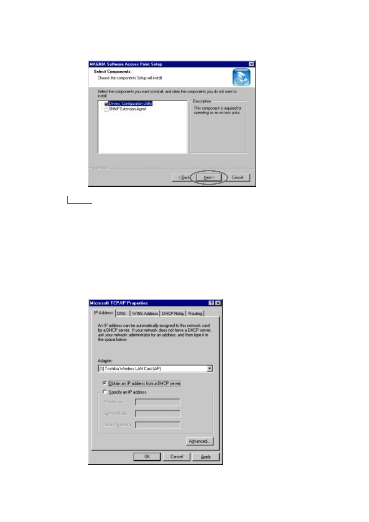
4. On this screen, select the components to be installed.
Click the [Next] button to start copying the files.
Memo
If you want to use the Access Point Configuration Utility to set up the Access Point from a remote
system, the SNMP Extension Agent has to be installed.
[3.3 Access Point Configuration Utility (Remote)]
!
[Appendix 1 SNMP Settings]
!
To install the SNMP Extension Agent, the SNMP service must be installed in advance. The
SNMP service is provided by the OS. For details, refer to the OS manual or online Help.
5. When the following screen is displayed, specify the IP address and click the [OK]
button.
9
Page 19

Memo
Some protocol components, such as NWLink protocol, demand a setup like a TCP/IP protocol.
Please perform and continue the required setup operations in the same way.
6. Select the wired LAN card to be connected and click the [OK] button.
If you do not connect a wired LAN card, select "Not Selected".
7. When the following screen is displayed, click the [Finish] button and reboot the system.
8. Set up the required items in the Access Point Configuration Utility.
By default, WEP and MAC address filtering are enabled.
[3.2 Access Point Configuration Utility (Local)]
10
Page 20
2.1.1.2 For installation in Windows 2000
When a wireless LAN card driver or software for other than this product is installed, uninstall it.
Install a wireless LAN card after installing the MAGNIA Software Access Point.
1. Log on as Administrator (or a user with equivalent rights).
2. Launch Setup.exe in the AP folder.
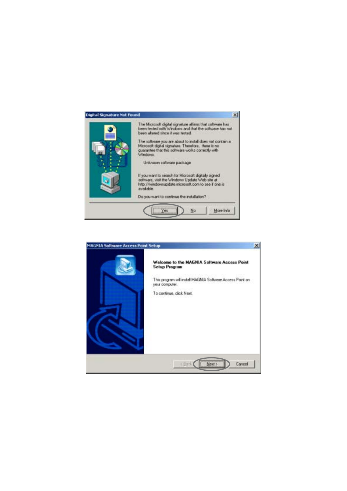
3. When the following screen is displayed, click the [Yes] button.
[2.1.2 Uninstalling the Software Access Point]
!
4. Click the [Next] button.
11
Page 21

5. On the screen, select the components to be installed.
Click the [Next] button to start copying the files.
Memo
If you want to use the Access Point Configuration Utility to set up the Access Point from a remote
system, the SNMP Extension Agent has to be installed.
[3.3 Access Point Configuration Utility (Remote)]
!
[Appendix 1 SNMP Settings]
!
To install the SNMP Extension Agent, the SNMP service must be installed in advance. The
SNMP service is provided by the OS. For details, refer to the OS manual or online Help.
6. Select the wired LAN card to be connected, and click the [OK] button.
If you do not connect a wired LAN card, select "Not selected".
12
Page 22
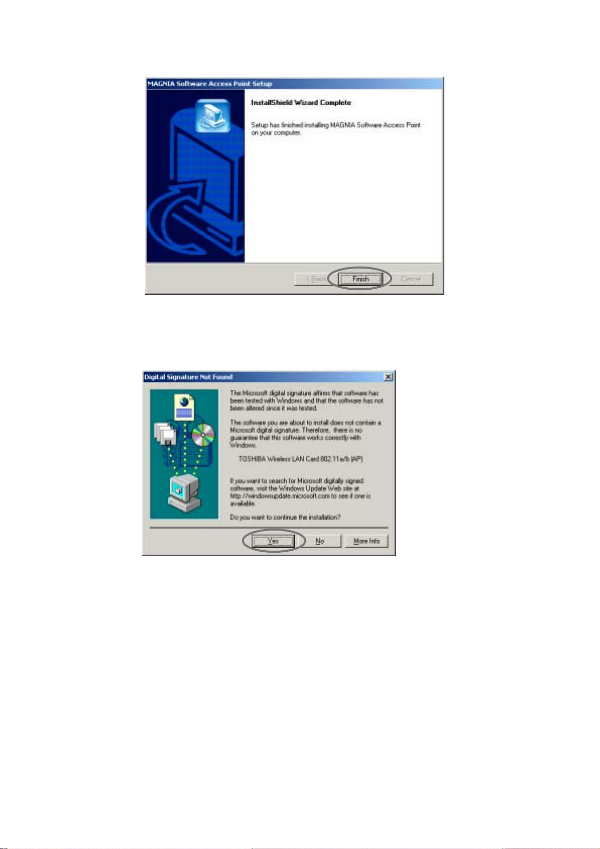
7. When the following screen is displayed, click the [Finish] button.
8. Install the wireless LAN card.
Refer to the server's manual for more information.
9. When the following screen is displayed, click the [Yes] button to start to copy the files.
The driver's installation is completed.
10. Setup the required items in the Access Point Configuration Utility.
By default, WEP and MAC access filtering are enabled.
[3.2 Access Point Configuration Utility (Local)]
13
Page 23

2.1.1.3 For installation in Server 2003
Install a wireless LAN card after installing the MAGNIA Software Access Point.
1. Log on as Administrator (or a user with equivalent rights).
2. Launch Setup.exe in the AP folder.
3. When the following screen is displayed, click the [Continue Anyway] button.
4. Click the [Next] button.
14
Page 24

5. On the screen, select the components to be installed.
Click the [Next] button to start copying the files.
Memo
If you want to use the Access Point Configuration Utility to set up the Access Point from a remote
system, the SNMP Extension Agent has to be installed.
[3.3 Access Point Configuration Utility (Remote)]
!
[Appendix 1 SNMP Settings]
!
To install the SNMP Extension Agent, the SNMP service must be installed in advance. The
SNMP service is provided by the OS. For details, refer to the OS manual or online Help.
6. Select the wired LAN card to be connected, and click the [OK] button.
If you do not connect a wired LAN card, select "Not selected".
15
Page 25
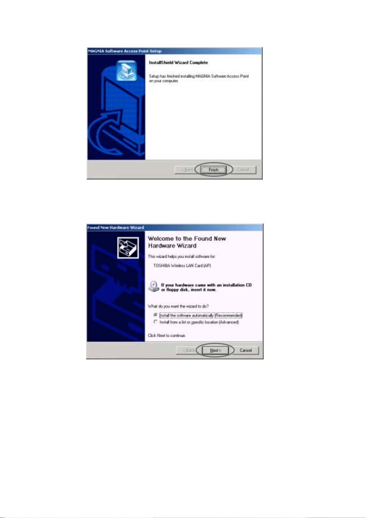
7. When the following screen is displayed, click the [Finish] button.
8. Install the wireless LAN card.
Refer to the server's manual for more information.
9. When the following screen is displayed, select [Install the software automatically] and
click the [Next] button.
16
Page 26

10. When the following screen is displayed, click the [Continue Anyway] button to start to
copy the files. Installation of the driver is completed.
11. Setup the required items in the Access Point Configuration Utility.
By default, WEP and MAC access filtering are enabled.
[3.2 Access Point Configuration Utility (Local)]
17
Page 27

2.1.2 Uninstalling the Software Access Point
This section describes the un-installation procedure for the MAGNIA Software Access Point.
2.1.2.1 For Windows NT/Windows 2000/Server 2003
1. Double-click the [Add/Remove Programs] icon on the Control Panel.
2. Delete "MAGNIA Software Access Point" by selecting it.
Subsequently, follow the uninstaller's instructions.
2.1.3 Upgrading the Software Access Point
This section describes the upgrading procedure for the MAGNIA Software Access Point.
2.1.3.1 For Windows NT
1. Log on as Administrator (or a user with equivalent rights).
2. Launch Setup.exe in the AP folder.
3. Click the [Yes] button.
4. When the following screen is displayed, click the [Finish] button and restart the system.
5. Set up the required items in the Access Point Configuration Utility.
After upgrading Access Point, the settings for 802.1X and RADIUS server are initialized.
[3.2 Access Point Configuration Utility (Local)]
18
Page 28

2.1.3.2 For Windows 2000/Server 2003
It is not possible to upgrade MAGNIA Software Access Point in Windows2000 nor Server2003.
Uninstall the earlier version of Software Access Point.
1. Log on as Administrator or a user with equivalent rights.
2. Activate the [Add/Remove Program] icon on the Control Panel and delete "MAGNIA
Software Access Point".
Refer to the un-installation process in the Software Access Point User's Guide of the
Software Access Point to be uninstalled.
3. Launch Setup.exe in the directory \AP of the installation CD.
[2.1.1 Installing the Software Access Point]
19
Page 29

2.2 Access Point Configuration Utility
If you install the Access Point Configuration Utility, you can set up the MAGNIA Software Access
Point from a remote system.
For details on using the Access Point Configuration Utility, see the following section.
[3.3 Access Point Configuration Utility (Remote)]
!
CL folder is under the following path on Server Setup Tool CD.
\Public\LAN\Toshiba\TSAP\CL
2.2.1 Installing Access Point Configuration Utility
1. Launch Setup.exe in the CL folder.
2. Click the [Next] button.
3. Specify the installation folder and click the [Next] button.
20
Page 30
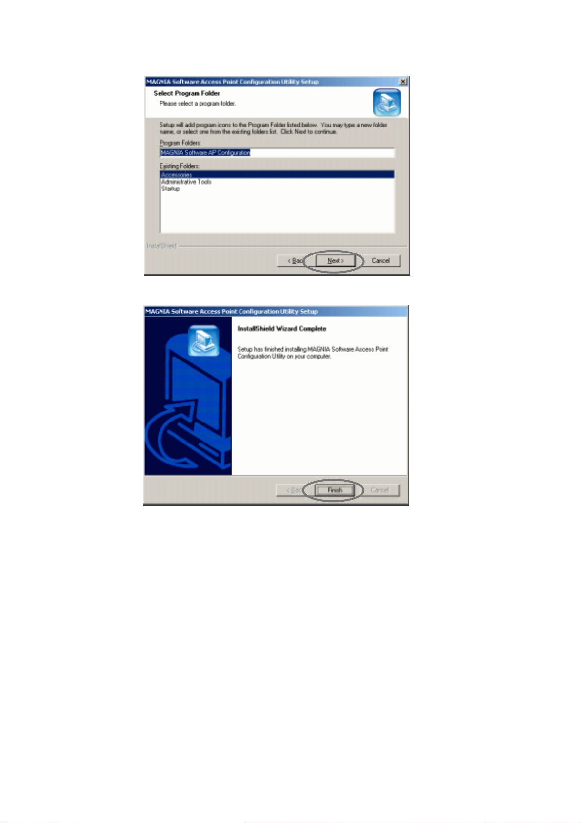
4. Specify the program folder and click the [Next] button.
5. When the following screen is displayed, click the [Finish] button.
21
Page 31

2.2.2 Uninstalling the Access Point Configuration Utility
The following describes the un-installation procedure.
1. Activate the [Add/Remove Programs] icon on the Control Panel.
2. Delete "MAGNIA Software Access Point Configuration Utility" by selecting it.
Next, follow the uninstaller's instructions.
2.2.3 Upgrading the Access Point Configuration Utility
The following describes the upgrading procedure.
1. Launch Setup.exe in the CL folder.
2. Click the [Yes] button to start copying the files.
Upgrading of the utility files is completed.
3. Click the [Finish] button.
22
Page 32

Chapter3 Utilities
Chapter3
Utilities
Page 33

3.1 Outline of Utilities
The utilities provided by this product are as follows.
1. Access Point Configuration Utility
This utility sets up the access point.
This utility has two modes, "Local (used on a server)" and "Remote (used from a PC).
2. Wired LAN Selection Utility
This utility connects to the wired LAN network and releases it.
3. Access Point Statistics Utility
This utility displays the operation statistics for the station and access point.
[3.2 Access Point Configuration Utility (Local)]
[3.3 Access Point Configuration Utility (Remote)]
[3.4 Wired LAN Selection Utility]
[3.5 Access Point Statistics Utility]
4. Access Point Log Utility
This utility collects and exports logs.
[Error! Not a valid result for table.]
24
Page 34

3.2 Access Point Configuration Utility (Local)
Sets up the MAGNIA Software Access Point.
This utility is installed at the same time the MAGNIA Software Access Point is installed.
3.2.1 Starting the utility
[Windows NT]
1. Double-click [Network] on the Control Panel on the server in which the Software
Access Point is installed.
2. Select the [Adapters] tab.
3. Select "TOSHIBA Wireless LAN Card (AP)" from the [Network Adapters] list box and
click the [Properties] button.
Page 35

[Windows 2000/Server 2003]
1. Double-click [Software Access Point] on the Control Panel on the server in which the
Software Access Point is installed.
26
Page 36

3.2.2 Using the utility
When the Access Point Configuration Utility is activated, the main screen has the following five
pages:
[Basic Setting]
[WEP]
[Access Restriction]
[Log Information]
[Hardware Resource] (displayed only when Windows NT is used)
Immediately after the utility starts, the current settings of the MAGNIA Software Access Point are
displayed on the respective pages.
Page 37

! Common to all the tabs
Item Description
[Wireless LAN adapter]
combo box
Specifies the wireless LAN adapter to setup.
Selection TOSHIBA Wireless LAN Card 802.11a/b(AP)/
TOSHIBA Wireless LAN Card(AP)
Default Depends on the adapter.
Remarks Names of the wireless LAN adapters provided with
the computer are displayed.
By selecting a wireless LAN adapter here,
information on each [Basic Setting] tab, [WEP] tab
or [Access Restriction] tab is changed to the
information corresponding to the selected adapter.
Characters such as "#2" may be added at the end
of the adapter's name.
[Connect to] button Changes the Software Access Point to be set.
When SNMP Extension Agent is installed on the remote
MAGNIA's Software Access Point, connection can be made
from this button.
The [Connect to] dialog box will appear.
[3.2.2.1[Connect to] dialog box]
[Close] button Quits the Access Point Configuration Utility.
[Refresh] button Refreshes the settings.
[Apply] button Applies the changes made on the settings.
28
Page 38

3.2.2.1 [Connect to] dialog box
Specifies the connection destination.
! [Connect to] dialog box
Item Description
[Local Computer]
radio button
[Remote Computer]
radio button
[Computer Name]
combo box
[Community Name]
edit box
[Connect] button Connects to the destination specified.
[Cancel] button Closes the dialog box without connecting.
Connects to the computer on which the Access Point Software
Utility is activated.
Remarks When making this connection, it is necessary to
activate the Access Point Software Utility on the
MAGNIA which is to be setup. It cannot be
connected from other computers.
Connects to other MAGNIA (Access Point) from the computers
on which the Access Point Software Utility is activated.
SNMP service and SNMP Extension Agent should be installed on
the remote MAGNIA (Access Point).
Remarks When connecting to [Remote Computer], it is also
necessary to specify [Computer Name] and
[Community Name].
Specifies the name or IP address of MAGNIA (Access Point)
Default None
Remarks Up to 10 recent connection histories remain.
Specifies the SNMP community name to use for connection.
The name should be the same as the one specified on MAGNIA
(Software Access Point) to be connected to.
Default None
Remarks See the following section, too.
[Appendix 1 SNMP Settings]
Page 39

3.2.2.2 [Basic Setting] tab
Makes basic settings of the MAGNIA Software Access Point.
! [Basic Setting] tab
Item Description
[Frequency Band]
combo box
[Access Point Name]
edit box
Specifies the frequency band used currently.
Selection IEEE 802.11b (2.4GHz)/IEEE 802.11a (5GHz)
Default Depends on the card.
Remarks Enabled frequency band differs according to the
Specifies the name to identify the access point.
Characters ASCII characters
Range Up to 32 letters
Default MAGNIA Software AP
wireless LAN cards and software.
ASCII characters include alphanumeric characters
and the following symbols:
!"#$%&'()*+,-./:;<=>?@[\]^_`{|}~
(Continues on the next page)
30
Page 40

Item Description
[Network Name (ESSID)]
edit box
[Don’t accept station with
network name "ANY"]
check box
Specifies the name of the logical network configured by the
access point.
The same setting item is provided on the station that runs in
infrastructure mode. The same name as the access point to be
connected to must be specified in the setting item.
Characters ASCII characters
ASCII characters include alphanumeric characters
and the following symbols:
!"#$%&'()*+,-./:;<=>?@[\]^_`{|}~
Range Up to 32 letters
Default MAGNIA
Remarks If its default is not changed, a third person may
connect to the access point by mistake. Please
change it.
See the following section, too.
[Appendix 2 Security]
Specifies whether to accept a connection request from a
network having a special "network name (ESSID)."
Selection
Checkbox
is selected
Checkbox
is cleared
A station can be connected only
when the network name matches.
A station having network name "ANY"
or a null character can be connected.
Default Checkbox is cleared
Remarks This item is enabled when [Toshiba Wireless LAN
Card (AP)] is selected in [Wireless LAN adapter].
See the following section, too.
[Appendix 2 Security]
(Continues on the next page)
Page 41

Item Description
[Country Name]
combo box
[Turbo mode]
check box
[Channel Number]
combo box
Specifies the country where Wireless LAN Card and the
software are used.
Selection Depends on the card.
Default Depends on the card.
Remarks Generally, each country has to follow regulations
on the use of radios that are defined in that
country. (Available wavelengths and the
transmission frequencies differ according to the
country.) When the card defines enabled specific
countries, it is not necessary to select a country
name. Confirm that the correct country is
displayed.
If not (if the card does not define any specific
country), you need to select a country name in this
item.
This item is enabled when [IEEE 802.11a(5GHz)] is
selected in [Frequency Band].
Specifies whether to use turbo mode.
Selection
Checkbox
is selected
Throughput (logical value) becomes
108 Mbps.
However, the number of enabled
channels is decreased.
Checkbox
is cleared
Throughput (logical value) becomes
54 Mbps.
Default Checkbox is cleared
Remarks When using turbo mode, the enabled channel will
be changed.
This item is enabled when [IEEE 802.11a(5GHz)] is
selected in [Frequency Band]. It is disabled
depending on the country and in this case, the
item is disabled.
Specifies the channel number to be used for communication.
Default 10 (when [IEEE 802.11a(2.4GHz)] is selected in
[Frequency Band])
The default differs depending on the country when
[IEEE 802.11a(5GHz)] is selected in [Frequency
Band]. (Ex. 52 for America)
Remarks When an adjacent access point uses the same
channel number, two access points interfere with
each other, resulting in deteriorated throughputs.
If so, change the number of either channel.
(Continues on the next page)
32
Page 42

Item Description
[Distance between Aps]
combo box
[Multicast Rate]
combo box
[DTIM Period]
edit box
Specifies the size of the area covered by access points.
Selection Large/Medium/Small
Default Large
Remarks It is recommended to select [Large] first, then
make the size smaller, checking the range of the
radio broadcast. Do not select an unnecessarily
large area as this may effect security.
See the following section, too.
[Appendix 2 Security]
This item is enabled when [TOSHIBA Wireless LAN
Card (AP)] is selected in [Wireless LAN adapter].
Specifies the transmission rate of multicast packets sent from
the access point.
Selection 1Mbps/ 2Mbps/ 5.5Mbps/11Mbps
Default 2Mbps
Remarks This item is enabled when [TOSHIBA Wireless LAN
Card (AP)] is selected in [Wireless LAN adapter].
Specifies the send timing of multicast packets in power save
mode.
Characters Numeric
Range 1-255
Default 1
Remarks When the value is default (1), a multicast packet is
sent at every beacon. When the value is 3,
multicast packets are accumulated in the buffer
and sent every third beacon.
Although a value from 1 to 255 can be specified, it
is recommended to set 1 for normal operation.
DTIM is an acronym of Delivery Traffic Indication
Map.
Page 43

3.2.2.3 [WEP] tab
Makes settings for the WEP key and 802.1X function.
See the following section, too.
For details on the 802.1X function, see the following chapter.
[Appendix 2 Security]
!
[Chapter4 802.1X Function]
!
34
Page 44

! [WEP] tab
Item Description
[802.1X]
combo box
[Distribute key]
check box
[Reauthenticate before
key distribution]
check box
[Key change interval
(seconds)]
edit box
Specifies whether to use the 802.1X function.
Selection
Not used It does not use 802.1X function.
Used It uses 802.1X function.
Used (non-
802.1X
Both stations that use the 802.1X
function and those that don't coexist.
stations are
permitted
to coexist.)
Default Not used
Specifies whether to dynamically distribute the key.
Checkbox
It dynamically distributes the key.Selection
is selected
Checkbox
is cleared
It does not dynamically distribute the
key.
Default Checkbox is cleared
Remarks This item is enabled when [Used] is selected in
[802.1X].
Specifies whether to make authentication when distributing the
key.
Selection
Checkbox
is selected
Checkbox
is cleared
It does authentication when
distributing the key.
It does not do authentication when
distributing the key.
Default Checkbox is cleared
Specifies in seconds the interval with which the key is changed
and distributed to each station
Characters Numeric
Range 1-65535
Default 600 seconds
(Continues on the next page)
Page 45

Item Description
[Key Length]
radio button
Specifies the length of the key to be distributed.
Selection
5bytes/13bytes
(When [TOSHIBA Wireless LAN Card(AP)] is selected
in [Wireless LAN Adapter])
5bytes/13bytes/16bytes
(When [TOSHIBA Wireless LAN Card 802.11a/b(AP)]
is selected in [Wireless LAN Adapter])
Default 5 bytes
Remarks Increasing length also increases security. To
improve security, use the greatest length possible.
[RADIUS Setting] button Specifies the information for RADIUS server.
Setup is necessary when using the 802.1X function.
[RADIUS Setting] dialog box will appear.
[3.2.2.4 [RADIUS Setting] dialog box]
[Enable WEP]
check box
Specifies whether to use WEP to encrypt communication data.
Checkbox
It uses WEP.Selection
is selected
Checkbox
It does not use WEP.
is cleared
Default Checkbox is selected
Remarks Using WEP is recommended to improve security.
When this check box is selected, you must select
one of the cryptographic keys 1 to 4 explained next
and specify the cryptographic key in the edit box.
A station that does not use WEP or whose key is
inconsistent cannot be connected to the access
point.
WEP is an acronym of Wired Equivalent Privacy.
(Continues on the next page)
36
Page 46

Item Description
[Keys 1 to 4]
edit box
Selects one of the keys 1 to 4 and specifies the WEP
cryptographic key to send data.
Characters ASCII character string or hexadecimal number.
ASCII characters include alphanumeric characters
and the following symbols:
!"#$%&'()*+,-./:;<=>?@[\]^_`{|}~
Range Bytes specified in [Key Length].
Default "WEP00"
(when [TOSHIBA Wireless LAN Card (AP) is
selected in [Wireless LAN adapter]).
"WEP0000000000"
(when [TOSHIBA Wireless LAN Card
802.11a/b(AP)] is selected in [Wireless LAN
adapter]).
Remarks Select one of the following formats.
-ASCII Characters
-Hexadecimal numbers
Please change the default for the improved
security.
Memo
If WEP is enabled, network throughput is deteriorated by encryption processing.
Page 47

3.2.2.4 [RADIUS Setting] dialog box
Sets rules for the RADIUS server that does authenticate.
! [RADIUS Setting] dialog box
Item Description
[Rule Name]
list box
[Add New] button
[Delete] button Deletes rules.
[Edit] button Edits rules.
[Move Up][Move Down]
button
Specifies the rules to enable.
This item is disabled when connecting MAGNIA Software Access
Point that is a version earlier than V3.0.
Default Checkbox is selected (Rule name is "Default")
Remarks Check box is selected when rules are added or
Adds rules.
[RADIUS Setting-Rule-Add/Edit] dialog box will appear.
[3.2.2.5 [RADIUS Setting - Rule - Add/Edit] dialog box]
Remarks Up to 100 rules can be set.
[RADIUS Setting-Rule-Add/Edit] dialog box will appear.
[3.2.2.5 [RADIUS Setting - Rule - Add/Edit] dialog box]
Changes the priority of the rules.
Priority is assigned in ascending order.
Checkbox
is selected
Checkbox
is cleared
edited.
It makes the rules enabled.Selection
It makes the rules disabled.
(Continues on the next page)
38
Page 48

Item Description
[RADIUS Server]
list box
[Edit]
button
[Move Up][Move Down]
button
[OK]
button
[Cancel]
button
Displays the RADIUS servers' hostnames or IP addresses.
Specify whether to use the RADIUS server or not.
Four RADIUS servers can be setup for one rule.
Selection
Checkbox
is selected
Checkbox
is cleared
It applies the rules to the RADIUS
server.
It does not apply the rules to the
RADIUS server.
Default Checkbox is cleared.
The RADIUS servers' default names are
"RADIUS1", "RADIUS2", "RADIUS3" and
"RADIUS4".
Specify appropriate host names and IP
addresses.
Remarks The access point sends inquiries in order to valid
RADIUS servers until the authentication succeeds
or fails.
Specifies the information about RADIUS server.
[RADIUS Setting-RADIUS] dialog box will appear.
[3.2.2.6 [RADIUS Setting - RADIUS] dialog box]
Remarks After editing the information the checkbox is
selected.
Changes the priority of the RADIUS servers to which the rules are
applied.
Priority is assigned in ascending order.
Closes the dialog box and saves any changes you have made.
Closes the dialog box without saving any changes you have
made.
Page 49

3.2.2.5 [RADIUS Setting - Rule - Add/Edit] dialog box
Sets rules which apply to the RADIUS server.
! [RADIUS Setting - Rule - Add/Edit] dialog box
Item Description
[Rule Name]
edit box
[Rule(Determine the
strings to match the
EAP/Identity.)]
edit box
Specifies rule names.
Characters ASCII characters
ASCII characters include alphanumeric characters
and the following symbols:
!"#$%&'()*+,-./:;<=>?@[\]^_`{|}~
Range Up to 512 letters
Default Not set for adding dialog box.
Specified rule name for editing dialog box.
Specifies the rules.
Set the EAP/Identity that the station uses.
Rules are applied when the characters set here match the
station's EAP/identity, and then the authentication is started.
The RADIUS server to use for the authentication can be fixed by
each rule. When the characters and station's EAP/Identity do not
match, the authentication is not started and the process will be
targeted to the next rule.
Range 1024 letters
Input
format
Default *
<Domain name>\<user name>
<user name>@<domain name>
Wildcards;" * " and "?" are enabled.
By separating the rules with return codes, multiple
rules can be set.
(Continues on the next page)
40
Page 50

Item Description
Remarks Example of settings:
<Domain name>\<user name>
TOSHIBA\user01:
(Direct addressing)
TOSHIBA\*:
All the users under the domain name "TOSHIBA"
TOSHIBA\user??:
Users who have two arbitrary characters after
"user", under the domain name "TOSHIBA"
<user name>@<domain name>
user01@toshiba.com:
(Direct addressing)
*@toshiba.com:
All the users under the domain name
"toshiba.com"
user??@toshiba.com:
Users who have two arbitrary characters after
"user", under the domain name "toshiba.com"
[OK] button Closes the dialog box and saves any changes you
have made.
[Cancel] button Closes the dialog box without saving any changes
you have made.
Page 51

3.2.2.6 [RADIUS Setting - RADIUS] dialog box
Specifies the connection to the RADIUS server.
! [RADIUS Setting RADIUS] dialog box
Item Description
[IP Address(Host Name)]
edit box
[Port]
edit box
[Shared secret]
edit box
[Time-out]
edit box
[OK] button Closes the dialog box and saves any changes you have made.
[Cancel] button Closes the dialog box without saving any changes you have
Specifies the IP address or host name of the RADIUS server.
Host name cannot be specified when connected to MAGNIA
Software Access Point that is an earlier version than V3.0.
Characters Unlimited (V3.0)
Only IP address (earlier version than V3.0)
Range Up to 512 letters (V3.0)
Enabled IP address (earlier version than V3.0)
Default None
Specifies the UDP port number to be used for communication
with the RADIUS server
Characters Numeric
Range 1-65535
Default 1812
Specifies the shared secret of the RADIUS server.
Characters ASCII characters
ASCII characters include alphanumeric characters
and the following symbols:
!"#$%&'()*+,-./:;<=>?@[\]^_`{|}~
Range Up to 256 letters
Default None
Note Shared secret is a password for communication
between the access point and the RADIUS server.
Specifies a time-out value in seconds.
Characters Numeric
Range 1-65535
Default 20 seconds
made.
42
Page 52

3.2.2.7 [Access Restriction] tab
Restrains specific wireless LAN stations from accessing the network by registering permissible
MAC addresses. See the following section, too.
[Appendix 2 Security]
!
! [Access Restriction] tab
Item Description
[Enable MAC address
filtering]
check box
Specifies whether to enable access restraints on wireless LAN
stations by registering permissible MAC addresses.
Default Checkbox is selected
Remarks Enabling filtering by MAC address is
Checkbox
is
selected
Checkbox
is cleared
recommended for security.
Enables filtering by MAC address.Selection
Disables filtering by MAC address.
(Continues on the next page)
Page 53

Item Description
[Access permitted MAC
address]
Lists the MAC addresses of the wireless LAN stations that are
permitted to access the network.
list box
[Add New] button Manually adds MAC addresses to be permitted to access the
network.
Use one of the following formats to specify a MAC address:
XXXXXXXXXXXX
XX:XX:XX:XX:XX:XX
XX-XX-XX-XX-XX-XX
(X is 0 to 9 or A to F.)
[Delete] button Removes an access-enabled MAC address.
A MAC address selected from the [Access permitted MAC
address] list can be removed.
[Import from File] button Selects a MAC address from a MAC addresses list file and add
it. Use one of the following formats to specify a MAC address:
XXXXXXXXXXXX
XX:XX:XX:XX:XX:XX
XX-XX-XX-XX-XX-XX
(X is 0 to 9 or A to F.)
If an improper MAC address is found in the file, it will be
skipped.
When creating files beforehand, use the CSV format.
[Export to File] button Saves the addresses in the [Access permitted MAC address] list
to a file.
[Access rejected MAC
address]
list box
Lists the MAC addresses of the wireless LAN stations that were
rejected by the access point.
It is possible to select MAC addresses and permit them.
[Permit] button Permits a MAC address, selected from the [Access rejected
MAC address] list, to access the network.
One or more MAC addresses can be selected.
[Clear All] button Clears all MAC addresses from the [Access rejected MAC
address] list.
44
Page 54

3.2.2.8 [Log Information] tab
Activates Access Point Statistics Utility and Access Point Log Utility.
! [Log Information] tab
Item Description
Statistics [Launch]
button
Logging [Launch]
button
Activates Access Point Statistics Utility.
Activates Access Point Log Utility.
[3.5 Access Point Statistics Utility]
[Error! Not a valid result for table.]
Page 55

3.2.2.9 [Hardware Resource] tab
Sets hardware resource items.
This tab is displayed only when Windows NT is used.
! [Hardware Resource] tab
Item Description
[IRQ Number]
combo box
[I/O Base Address]
combo box
Specifies the identification number used for the wireless LAN
card to post an interrupt to the OS.
Default 3
Specifies the I/O address space used for the wireless LAN card
to perform I/O with the OS.
Default 0x0400
46
Page 56

3.3 Access Point Configuration Utility (Remote)
Sets up the MAGNIA Software Access Point from a remote PC.
The versions of MAGNIA Software Access Point which are more recent than V2.0 can be
connected.
Because communication is made by SNMP during the connection, the SNMP Extension Agent
needs to operate on the server (access point). For information on installing and setting up the
SNMP Extension Agent, see the following sections.
[2.1.1.1 For installation in Windows NT]
!
[2.1.1.2 For installation in Windows 2000]
!
[2.1.1.3 For installation in Server 2003]
!
[Appendix 1 SNMP Settings]
!
For the installation procedure of this utility, see the following section.
[2.2.1 Installing Access Point Configuration Utility]
!
Page 57

3.3.1 Starting the utility
1. Select [Programs]-[MAGNIA software AP Configuration]-[AP Configuration Utility].
2. In the [Computer Name] combo box, enter the computer name or IP address of the
server (access point).
In the [Community Name] edit box, enter the name of the community to be used.
Click the [Connect] button.
48
Page 58

3.3.2 Using the utility
The method for using the utility is the same as when you use the Access Point Configuration
Utility in local mode (on the server). However, the [Hardware resource] page is not displayed.
The versions of MAGNIA Software Access Point which are more recent than V3.0 display the [Log
Information] tab.
For details, see the following section.
Memo
When you access from a wireless LAN station, do not write the information to the access point to
which the station has connected.
[3.2 Access Point Configuration Utility (Local)]
!
Page 59

3.4 Wired LAN Selection Utility
This utility connects wireless and wired LAN networks with each other (or releases the
connection). When the wireless and wired LAN networks are connected, the PC on each network
can communicate with the other.
This utility is installed at the same time with the MAGNIA Software Access Point is installed.
3.4.1 Starting the utility
[Windows NT]
1. Double-click [Network] on the Control Panel on the server in which the Software
Access Point is installed.
2. Select the [Protocols] tab.
3. Select "TOSHIBA MAGNIA Software AP (Distribution System)" from the [Network
Protocols] list box and click the [Properties] button.
50
Page 60

[Windows 2000/Server 2003]
1. Activate [Selection of Wired LAN] on the Control Panel on the server in which the
Software Access Point is installed.
Page 61

3.4.2 [Selection of Wired LAN Network Adapter] dialog box
When the Wired LAN Selection Utility is started, the following dialog box is displayed.
Select the wired LAN card that you want to connect to, and click the [OK] button. If you do not
want to connect to it, select "Not selected."
! [Selection of Wired LAN Network Adapter] dialog box
Item Description
Selection list box
[OK] button Closes the dialog box and saves any changes you have made.
[Cancel] button Closes the dialog box without saving any changes you have
When wired LAN card is selected
When a wired LAN card is selected, the protocol and service, bound to the wireless LAN card, are
forcibly released. At this point, only " TOSHIBA MAGNIA Software AP (Distribution System)" is
bound.
However, on Windows 2000 or Server 2003, NWLink protocol is being used, "NWLink NetBIOS",
"File and Printer Sharing for Microsoft Networks", and "Client for Microsoft Networks" are still
bound. Please leave the above-mentioned component as it is.
!Notice!
If the driver of the selected wired LAN card is running abnormally, communication between the
wireless LAN station and the PC on the wired LAN and between the wireless LAN station and
server (access point) is disabled.
In the case of Windows 2000 or Server 2003, note that unless the network cable is connected, the
driver becomes invalid.
Selects the wired LAN card that you want to connect to.
If you do not want to connect to the wired LAN card, select " Not
selected"
Default Selected during installation
Remarks If the cable is not connected to the wired LAN
card, "Network cable unplugged." is displayed
at the end of the item.
made.
When "Not selected" is selected
If "Not selected" is selected, TOSHIBA MAGNIA Software AP (Distribution System) is forcibly
removed from all wired LAN cards.
If "Not selected" is selected from where the wired LAN card is selected, only TOSHIBA MAGNIA
Software AP (Distribution System) is bound to the wireless LAN card. Manually bind necessary
protocols and services. For information on the binding, refer to the manual or online Help of the
52
Page 62

OS.
When AFT/ALB of Intel LAN card is used
When using the AFT (Adapter Fault Tolerance)/ALB (Adaptive Load Balancing) function on the
Intel LAN card driver, note the following.
· When newly composing the AFT/ALB combination or changing the composition, temporarily
select "Not selected" in the Wired LAN Selection Utility. After completing the AFT/ALB
composition, reselect the wired LAN card to be connected.
Unless the above-mentioned procedure is done, communication between a wireless LAN and
wired LAN may not be done normally. In this case, please reconfigure by using the Wired LAN
Selection Utility.
Page 63

3.5 Access Point Statistics Utility
This utility displays the operation statistics of the MAGNIA Software Access Points. You can see
the packet's transmission and reception information for each adapter and station as well as the
802.1X authentication information.
The utility is installed at the same time the MAGNIA Software Access Point is installed.
3.5.1 Starting the utility
To startup the utility, first click the Access Point Configuration Utility's [Log Information] tab.
3.5.2 Procedure
When the Access Point Statistics Utility starts up, the screen below will be displayed. The menu commands are
explained below.
[3.2.2.8 [Log Information] tab]
!
Menu Command Description
[File]
-[New Connection]
[File]-[Exit] Exits the Access Point Statistics Utility.
[View]-[Adapter Statistics] Displays the adapter's operation statistics.
[View]
- [Station Statistics]
Changes the computer whose operation statistics is displayed.
The [New Connection] dialog box appears.
[3.2.2.1 [Connect to] dialog box]
Displays the adapter statistics screen.
[3.5.3 Adapter Statistics]
Displays the station's operation statistics.
Displays the station statistics screen.
[3.5.4 Station Statistics]
(Continues on the next page)
54
Page 64

Menu Command Description
[View]
-[Auto Refresh]
[Help]
-[About ApStat . . .]
[Help]
-[View Help]
Changes the operation statistics update interval.
Displays the Access Point Statistics Utility's version information,
the target access point's version information, and the copyright
information.
Displays the Help index.
3.5.3 Adapter Statistics Screen
This screen enables you to check the adapter's operation statistics below.
LAN adapter statistics
Access point statistics
Bridge statistics
[3.5.5 Setting the Auto-Refresh Interval]
Page 65

3.5.3.1 LAN Adapter statistics
The table below shows the items displayed for the LAN adapter statistics.
Value Description
Device name Name of the LAN adapter (device name the OS indicates).
MAC address MAC address of the LAN adapter.
Type LAN adapter type.
Status Status of the LAN adapter.
TxFrames Total number of frames transmitted by the LAN adapter.
TxBytes Total length (total bytes) of the frame transmitted by the LAN
TxErrors Total number of errors occurred during transmission by the LAN
RxFrames Total number of frames received by the LAN adapter.
RxBytes Total length (total bytes) of the frame received by the LAN
RxErrors Total number of errors occurred during reception by the LAN
"Wired," "Wireless (11b)," or "Wireless (11a)" is displayed.
Either [Disabled] or [Enabled] is displayed.
adapter.
adapter.
adapter.
adapter.
3.5.3.2 Access Point statistics
The table below shows the items displayed for the access point statistics.
Value Description
TxUnicastFrames Total number of frames transmitted by the access point to a
TxUnicastBytes Total frame length (total bytes) transmitted by the access point
TxMulticastFrames Total number of frames transmitted by the access point to
TxMulticastBytes Total frame length (total bytes) transmitted by the access point
RxUnicastFrames Total number of frames received by the access point for a single
RxUnicastBytes Total frame length (total bytes) received by the access point for a
single station.
to a single station.
multiple stations.
to multiple stations.
station.
single station.
(Continues on the next page)
56
Page 66

Value Description
RxMulticastFrames Total number of frames received by the access point for multiple
RxMulticastBytes Total frame length (total bytes) received by the access point for
TxRetrySucceeded
Frames
TxRetryFailedFrames Total number of frames that could not be transmitted even via
FCS Errors Total number of frames received and destroyed due to Frame
ICV Errors Total number of frames received and destroyed due to Integrity
3.5.3.3 Bridge statistics
The table below shows the items displayed for the bridge statistics.
stations.
multiple stations.
Total number of frames that could be transmitted via retry.
retry.
Check Sequence error.
Check Value error.
Value Description
(Fw) TxFrames Total number of frames transferred to the destination LAN
adapter.
(Fw) TxBytes Total frame length (total bytes) transferred to the destination LAN
adapter.
(Fw) RxFrames Total number of frames transferred from the destination LAN
adapter.
(Fw) RxBytes Total frame length (total bytes) transferred from the destination
LAN adapter.
Page 67

3.5.4 Station Statistics Screen
This screen enables you to check the station statistics.
When the station statistics is displayed, the wireless LAN adapter is displayed within the directory
tree. The stations connected to the wireless LAN adapter are displayed as child nodes of the
adapter.
The dimmed icons indicate disabled adapters.
Also, if there is any marking on the station's icon, it indicates IEEE 802.1X authenticate state.
The meaning of the markings are as follows:
Marking Meaning
Authentication successful.
Authentication failed.
Authentication pending.
Caution(Station with a possible unauthorized access attempt)
Click on the "LAN Adapter" node to see the table of information on all the stations connected to
the adapter. Click on the "Station" node to see the station's detailed information.
58
Page 68

3.5.4.1 Statistics displayed in table
The statistics displayed in table are explained below.
Value Description
MAC address MAC address of the station.
Status Status of the station.
[Disabled], [Enabled], [Requesting authentication],
[Authenticating], [Authentication failed], [Authentication
succeeded], or [Unknown] is displayed.
TxFrames Total number of frames transmitted (unicast) by the access point
to the station.
TxBytes Total frame length (total bytes) transmitted (unicast) by the
access point to the station.
RxFrames Total number of frames received (unicast + multicast) by the
access point from the station.
RxBytes Total frame length (total bytes) received (unicast + multicast) by
the access point from the station.
Elapsed Elapsed time after the association was established.
Idle Time Elapsed time after the last data was received.
dB Min Minimum value of the received frame's radio wave strength.
dB Last Radio wave strength of the last received frame.
dB Max Maximum value of the received frame's radio wave strength.
EAP/Identity User ID for 802.1X authentication.
3.5.4.2 Statistics displayed in detailed list
Items displayed in detail are explained below.
Value Description
MAC address MAC address of the station.
Status Status of the station.
[Disabled], [Enabled], [Requesting authentication],
[Authenticating], [Authentication failed], [Authentication
succeeded], or [Unknown] is displayed.
TxUnicastFrames Total number of frames transmitted (unicast) by the access point
to the station.
TxUnicastBytes Total frame length (total bytes) transmitted (unicast) by the
access point to the station.
(Continues on the next page)
Page 69

Value Description
RxUnicastFrames Total number of frames received (unicast) by the access point
from the station.
RxUnicastBytes Total frame length (total bytes) received (unicast) by the access
point from the station.
RxMulticastFrames Total number of frames received (multicast) by the access point
from the station.
RxMulticastBytes Total frame length (total bytes) received (multicast) by the access
point from the station.
RxUnicastFrames (<n>
Mbps)
Total number of frames received in <n> Mbps (unicast) by the
access point from the station.
<n> will be as follows:
For 802.11b: 1, 2, 5, 5.5, 8, 11
For 802.11a: 6, 9, 12, 18, 24, 36, 48, 54
Elapsed Time Elapsed time after the association was established.
Idle Time Elapsed time after the last data was received.
dB Min Minimum value of the received frame's radio wave strength.
dB Last Radio wave strength of the last frame received.
dB Max Maximum value of the received frame's radio wave strength.
EAP/Identity 802.1X authentication user ID.
EAP-Type 802.1X authentication type (MD5, TLS, TTLS, PEAP, etc.).
Authentication server
Name of authentication rule used for the authentication.
(Rule name)
Authentication server
Name of the RADIUS server used for the authentication.
(Server name)
Elapsed time after
Elapsed time since the first successful 802.1X authentication.
authorized
Rest time to new WEP
Remaining time until the next new WEP key is to be distributed.
key distribution
Interval time of new WEP
Time interval for distributing new WEP keys.
key distribution
Rest time to re-
Remaining time until the next re-authentication.
authentication
Interval time of re-
Time interval for re-authentication.
authentication
Successful
Total successful (re-) authentications in the past.
authentications
Failed authentications Total failed (re-) authentications in the past.
Authentication timeouts Total (re-) authentication timeouts in the past.
Invalid authentication
Total invalid authentication packets received in the past.
packets
60
Page 70

3.5.5 Setting the Auto-Refresh Interval
Set the display's update interval.
Item Description
[Refresh Interval]
edit box
[OK] button Closes the dialog box and saves any changes you have made.
[Cancel] button Closes the dialog box without saving any changes you have
Specifies the time interval (in sec.) at which the displayed
information is to be updated.
Range 1-60
Default 1(sec.)
made.
Page 71

3.6 Access Point Log Utility
This utility saves the MAGNIA Software Access Point's operation statistics as a CSV file. You can
save the packet's transmission/reception information for each adapter and station as well as the
802.1X authentication information. Third-party software, which can read CSV files, can be used to
create graphs based on the saved information.
The utility is installed at the same time the MAGNIA Software Access Point is installed.
3.6.1 Starting the utility
To startup the utility, first click the Access Point Configuration Utility's [Log Information] tab.
3.6.2 Procedure
Select the computer where the logs will be collected, the type of information to be collected, and
the adapters and stations whose information is to be collected.
Also set the log collection interval and select the folder where the logs are to be saved.
[3.2.2.8 [Log Information] tab]
!
62
Page 72

Item Description
[About ApLog]
dialog box
Target Access Point
[Select] button
[Adapter Statistics]
check box
Target adapter selection
[Station Statistics]
check box
Target station selection
Displays the utility's version information, the target access
point's version information, and copyright information.
Clicking the upper left icon on the title bar displays the menu.
Changes the computer where the logs are collected.
The destination setting dialog box appears.
[3.2.2.1 [Connect to] dialog box]
Specifies whether to collect the adapter statistics or not.
Checkbox is
Adapter statistics will be collected.Selection
selected
Checkbox is
cleared
Adapter statistics will not be
collected.
Default Checkbox is cleared.
Specifies the LAN card adapter that will collect the adapter
statistics.
Selection
All The adapter statistics will be
collected from all the LAN card
adapters.
Selected
Adapter Only
The adapter statistics will be
collected from the selected LAN
card adapter.
Default All
Remarks When [Selected Adapter Only] is selected, select
from the list the LAN card adapter to be used to
collect the adapter statistics.
Specifies whether to collect the station statistics or not.
Selection
Checkbox is
selected
Checkbox is
cleared
The station statistics will be
collected.
The station statistics will not be
collected.
Default Checkbox is cleared.
Specifies the station that will collect the station statistics.
Selection
All The station statistics will be
collected from all the stations.
Selected AP
Only
The station statistics will be
collected from the selected access
point.
Selected
Station
(MAC) only
The station statistics will be
collected from the selected MAC
address.
(Continues on the next page)
Page 73

Item Description
Default All
Remarks When [Selected AP only] is selected, select from
Sample Interval
[Interval] edit box
Specifies the time interval for log collection.
Range 1-60
Default 1
Sample Interval
[Units] combo box
Specifies the time unit for the log collection interval.
Item min./hour/day
Default min.
Log Folder Name
[Select] button
[Start]
button
Changes the folder where the logs will be saved.
The [Browse For Folder] dialog box will appear.
Starts the log collection.
The dialog box will close and the icon will appear on the task
tray.
[Cancel]
button
Quits the log collection utility.
The log collection will not start.
the list the access point that is to collect the
station statistics.
When [Selected Station (MAC) only] is selected,
select from the list the MAC address that is to
collect the station statistics.
[3.6.2.1 [Browse For Folder] dialog box]
[3.6.3 Task Tray Icon]
64
Page 74

3.6.2.1 [Browse For Folder] dialog box
Select the folder where the logs are to be saved.
When the log collection starts, a folder named "Adapter" and a folder named "Station" are created
in the folder selected here. And in each folder, a folder having the same name (characters which
cannot be used in the name will have substitute characters) as the adapter is created. The log files
will be stored in the respective adapter folders.
The types of files created are as follows.
The collected information is added in sequence to the end of the file.
Adapter statistics
<Save folder>\Adapter\< Adapter name>\AdpLog.csv
<Save folder>\Adapter\< Adapter name >\BrgLog to <Destination adapter>.csv
Station statistics
<Save folder>\Station\<Access point adapter name>\StaLog of <Station MAC address>.csv
Item Description
[OK] button Closes the dialog box and saves any changes you have made.
[Cancel] button Closes the dialog box without saving any changes you have
made.
[New folder] button Creates a new folder.
When using Windows98, Windows Me or Windows NT, the
[Make New folder] button may not be displayed.
If this happens, you have to create a save folder before you go
to the dialog box.
Page 75

3.6.3 Task Tray Icon
When the log collection starts, the icon below will appear on the task tray.
To stop the log, right-click this icon and select [Stop Logging].
3.6.4 Statistics Saved in the Log
The statistics saved in the log is displayed in a list for each item.
3.6.4.1 LAN Adapter Statistics
Value Description
Date Date when the data was collected.
Formats set under [Regional Options] on the control panel are
supported.
Time Time when the data was collected.
Formats set under [Regional Options] on the control panel are
supported.
State Status of the LAN adapter.
Either [Disabled] or [Enabled] will be displayed.
TxFrames Total number of frames transmitted by the LAN adapter.
TxBytes Total frame length (total bytes) transmitted by the LAN adapter.
TxErrors Total errors occurred during transmission by the LAN adapter.
RxFrames Total number of frames received by the LAN adapter.
RxBytes Total frame length (total bytes) received by the LAN adapter.
RxErrors Total errors occurred during reception by the LAN adapter.
66
Page 76

3.6.4.2 Access Point Statistics
Value Description
TxUnicastFrames Total number of frames transmitted by the access point to a
TxUnicastBytes Total frame length (total bytes) transmitted by the access point
TxMulticastFrames Total number of frames transmitted by the access point to
TxMulticastBytes Total frame length (total bytes) transmitted by the access point
RxUnicastFrames Total number of frames received by the access point for a single
RxUnicastBytes Total frame length (total bytes) received by the access point for a
RxMulticastFrames Total number of frames received by the access point for multiple
RxMulticastBytes Total frame length (total bytes) received by the access point for
TxRetrySucceeded
Frames
TxRetryFailedFrames Total number of frames that could not be transmitted even via
RxFcsErrorFrames Total number of frames received and destroyed due to FCS
RxIcvErrorFrames Total number of frames received and destroyed due to ICV
single station.
to a single station.
multiple stations.
to multiple stations.
station.
single station.
stations.
multiple stations.
Total number of frames that could be transmitted via retry.
retry.
(Frame Check Sequence) error.
(Integrity Check Value) error.
3.6.4.3 Bridge Statistics
Value Description
Date Date when the data was collected.
Time Time when the data was collected.
State Status of the destination LAN adapter.
(Fw) TxFrames Total number of frames transferred to the destination LAN
(Fw) TxBytes Total frame length (total bytes) transferred to the LAN adapter.
Formats set under [Regional Options] on the control panel are
supported.
Formats set under [Regional Options] on the control panel are
supported.
Either [Disabled] or [Enabled] will be displayed.
adapter.
Page 77

3.6.4.4 Station Statistics
Value Description
Date Date when the data was collected.
Time Time when the data was collected.
State [Disabled], [Enabled], [Requesting authentication],
TxUnicastFrames Total number of frames transmitted (unicast) by the access point
TxUnicastBytes Total frame length (total bytes) transmitted (unicast) by the
RxUnicastFrames Total number of frames received (unicast) by the access point
RxUnicastBytes Total frame length (total bytes) received (unicast) by the access
RxMulticastFrames Total number of frames received (multicast) by the access point
RxMulticastBytes Total frame length (total bytes) received (multicast) by the access
RxUnicastFrames
(<n> Mbps)
ElapsedTime Elapsed time after the wireless data link was established.
Formats set under [Regional Options] on the Control Panel are
supported.
Formats set under [Regional Options] on the Control Panel are
supported.
[Authenticating], [Authentication failed], [Authentication
succeeded], or [Unknown] is displayed.
to the station.
access point to the station.
from the station.
point from the station.
from the station.
point from the station.
Total number of frames received in <n> Mbps (unicast) by the
access point from the station.
<n> will be as follows:
For 802.11b: 1, 2, 5, 5.5, 8, 11
For 802.11a: 6, 9, 12, 18, 24, 36, 48, 54
IdleTime Elapsed time after the last data was received.
dB Min Minimum value of the received frame's radio wave strength.
dB Last Radio wave strength of the last frame received.
dB Max Maximum value of the received frame's radio wave strength.
EAP/Identity 802.1X authentication user ID.
EAP-Type 802.1X authentication type (MD5, TLS, TTLS, PEAP, etc.).
AuthRule Name of authentication rule used for the authentication.
AuthServer Name of the RADIUS server used for the authentication.
ElapsedTimeAuthorized Elapsed time since the first successful 802.1X authentication.
(Continues on the next page)
68
Page 78

Value Description
NewKeyTxWhen Remaining time until the next new WEP key is to be distributed.
NewKeyTxPeriod Distribution time interval of new WEP keys.
ReauthWhen Remaining time until the next re-authentication.
ReauthPeriod Time interval for re-authentication.
AuthSucceededCount Total successful (re-) authentication in the past.
AuthFailedCount Total failed (re-) authentication in the past.
AuthTimeoutCount Total (re-) authentication timeouts in the past.
InvalidAuthCount Total invalid authentication packets received in the past.
Page 79

Chapter4 802.1X Function
Chapter4
802.1X Function
Page 80

4.1 Overview
The 802.1X function restricts the connection of unauthorized stations by authenticating each
station. It rejects transmissions from unauthenticated clients and only permits communications
with authenticated users. Periodic re-authentication can also be performed to prevent
unauthorized access by hacking, etc. RADIUS and other servers can be used for user
authentication, and Windows 2000 or Server 2003’s "Internet Authentication Service" can also be
used.
You can use the 802.1X function only if the station and RADIUS server are compatible with the
802.1X function.
The 802.1X function has the following advantages in security and administration.
Security
Administration 3. Because the function dynamically distributes the WEP key, the
Memo
Although several authentication methods are prepared, the WEP key cannot be distributed in
some of those methods.
1. The function makes authentication during station connection and
permits only the station that has passed the authentication to
communicate. This function makes it difficult for an unauthorized
station to get in the network.
2. The function can dynamically distribute the WEP key. It
enhances security by periodically changing and distributing the
WEP key.
WEP key does not need to be set at each station.
72
Page 81

4.2 802.1X Function
This section explains the 802.1X function more specifically.
4.2.1 Required Environment
The following environment is required to use the 802.1X function.
AP
STA
RADIUS CA
AP Access point (this product). It operates on the MAGNIA server.
STA Wireless LAN station
The 802.1X function needs to be supported even on the station side.
RADIUS Abbreviation of Remote Authentication Dial In User Service. This server
authenticates STAs.
RADIUS must also be compatible with the 802.1X function.
CA Abbreviation of Certificate Authority. This server issues a digital certificate.
This server is required to use an authentication type that is called EAP-TLS
(Smart Card or other certificate).
Note that the above terms (abbreviations) are used in the subsequent explanations.
Page 82

4.2.2 Authentication and Distribution of WEP Key
This section explains authentication (re-authentication) and the distribution of the WEP key.
4.2.2.1 Authentication
Authentication starts when a wireless LAN station connects to the access point.
When the station connects, the access point issues a request to start authentication for that
station. Although the station that has received the request starts the authentication procedure,
the access point transfers all messages related to the authentication to the RADIUS server. That
is, the authentication itself is performed between the station and RADIUS server.
While the authentication procedure is performed, the station cannot join the network.
When the station passes the authentication process, the RADIUS server reports to the access
point.
When it receives the report, the access point has the station join the network.
The following shows the authentication procedure (successful example).
Authentication procedure (successful example)
AP
RADIUS
STA
(1) The station connects to the access point.
(2) A request to start authentication is sent from the access point to the station.
(3) The authentication procedure is performed between the station and RADIUS server.
(4) The RADIUS server reports to the access point that the station has passed the
authentication.
(5) The access point reports to the station that the station has passed the authentication.
The access point permits the station to communicate.
At this point, the WEP key can be distributed. (Whether the WEP key can be
distributed depends on the authentication type.)
(6) The station can join the network.
74
Page 83

4.2.2.2 Authentication type
Several types of authentication are available. The wireless LAN station and RADIUS server need
to predetermine which type of authentication to use mutually. If different types of authentication
are set, the authentication procedure cannot be performed and the authentication of the station
fails. Whether the WEP key can be distributed depends on the authentication type.
The following lists the typical types of authentication.
Name Description
MD5Challenge
EAP-TLS Authentication method using a digital certificate. It may be represented
EAP-TTLS TTLS stands for Tunneled TLS. It aims to execute the authentication
PEAP Abbreviation of Protected EAP. The basic concept is the same as with
Authentication method using the user name and password
In this type of authentication, the WEP key cannot be distributed.
by a "Smart Card or other Certificate."
To use this type of authentication, the certificate needs to be obtained
from the CA and stored in each station.
In this type of authentication, the WEP key can be distributed.
more securely and flexibly.
With TTLS, Phase 1 applies the TLS tunnel between the station and
authenticating server. Then in Phase 2, authentication is done in the
tunnel. Since this authentication method is not set as the fixed method,
the EAP authentication mentioned above and the usual PAP and CHAP
authentication methods can also be used if desired. (The authentication
methods that are supported depend on the RADIUS server and client
software.)
With Phase 1, the authentication is more secure. And with Phase 2, the
authentication is more flexible.
the EAP-TTLS.
Page 84

4.2.2.3 Distribution of WEP key
When authentication ends successfully, the access point distributes the WEP key to the station.
(Whether the WEP key can be distributed depends on the authentication type.)
The WEP key is created at random by the access point.
This product has the function that changes and redistributes the WEP key periodically or in
seconds. Security can be enhanced by changing the WEP key in a short time.
MAGNIA MAGNIA
New WEP
key
distributed
Old WEP key discarded
For details on the setting method, see the following section.
[3.2 Access Point Configuration Utility (Local)]
!
76
Page 85

4.2.2.4 Re-authentication
Security can be enhanced by periodically making re-authentication even after the station has
passed the authentication.
The re-authentication timing can be set in the following method.
Making re-authentication when the WEP key is distributed
Although this product has the function that periodically changes and distributes the WEP key, it
can be set so that re-authentication is made at that timing. For details on the setting method, see
the following section.
Setting a session time-out value for the RADIUS server
If the RADIUS server configuration contains a setting item of the session time-out value, its value
indicates a re-authentication interval.
In the case of "Internet Authentication Service" of Windows 2000 Server, the value of [Restrict
maximum session to] is the session time-out value.
The figure below is an example of settings on Windows 2000 Server.
On Server 2003, the value becomes the time ([Minutes client can be connected]) that the client
can be connected.
[3.2 Access Point Configuration Utility (Local)]
!
Page 86

4.2.3 Coexistence of Station Not Supporting the 802.1X Function
With the MAGNIA Software Access Point, a station that supports the 802.1X function (hereinafter
called the 802.1X station) and one that does not support that function (hereinafter called a non-
802.1X station) can be used together.
AP
RADIUS CA
STA
(802.1X)
Even when the two stations are used together, the WEP key can be distributed to the 802.1X
station. In this case, however, settings must be made so that communication is performed with
the specified WEP key for a non-802.1X station. This product uses WEP key 4 as the specified
key.
For details on the settings, see the following section.
When this product is used with the two stations mixed, security is as tight as when the 802.1X
function is not used.
STA
(non-802.1X)
!!!!!!!!!
[3.2 Access Point Configuration Utility (Local)]
[4.3.2 Configuration Example (2)]
!
78
Page 87

4.3 RADIUS Selection Function
When 802.1X authentication starts, this RADIUS selection function looks at the EAP/Identity sent
by the station and selects the suitable RADIUS server.
Router Router
CA-A
RADIUS-A
AP-A(MAGNIA)
STA-A
Domain A
4.3.1 RADIUS Server Role
The RADIUS server authenticates the station and restricts the connection to the access point.
As shown in the diagrams below, there are Domain A and Domain B and both have an access
point, RADIUS, and CA. The station connects to the access point in the same domain, and the
RADIUS server in the same domain authenticates the station.
Router Router
CA-B
STA-B
(Connected to
AP-A)
RADIUS-B
Domain B
AP-B(MAGNIA)
STA-B
(Connected to
AP-B)
CA-A
RADIUS-A
Domain A
AP-A(MAGNIA)
STA-A
CA-B
RADIUS-B
Domain B
AP-B(MAGNIA)
STA-B
(Connected to
AP-B)
Page 88

With this configuration, a station (STA B) in Domain B will be unable to connect to the access
point (AP A) in Domain A because the authentication will fail. This is because Domain A’s access
point (AP A) entrusts all authentication to Domain A’s RADIUS server (RADIUS-A).
Router Router
STA-B???
CA-A
RADIUS-A
Domain A
AP-A(MAGNIA)
STA-A
CA-B
STA-B
(Connected to
AP-A)
RADIUS-B
Domain B
AP-B(MAGNIA)
If the RADIUS server is compatible with the authentication proxy function (RADIUS Proxy
function), the above problem can be resolved by just change settings on the RADIUS servers.
However, not all RADIUS servers are compatible with the authentication proxy function.
It is possible to create an account for each domain just for the authentication. However, having a
duplicate account would add to the cost and be troublesome.
The RADIUS selection function is an easy solution to this problem.
4.3.2 Setting Rules and Selecting the RADIUS Server
The access point selects the RADIUS server in accordance with the preset information.
The information to be preset is explained below.
4.3.2.1 Setting Rules
When selecting the RADIUS server, the access point refers to the EAP/Identity.
The EAP/Identity is an identifier sent from the station when the 802.1X authentication starts.
Normally, it is written in the format shown below:
Expression using the NetBIOS
domain
NAI format expression <Username>@<Domain name>
<Domain name>\<Username>
Example: DomainA\User01
Example: User01@DomainA.local
80
Page 89

Use one of the above expressions when registering the EAP/Identity with the access point. The
access point will compare the EAP/Identity sent from the station with the registered EAP/Identity.
If they both match, a rule is established.
You can give the rule a name. Create a rule name that can be easily remembered, such as "RuleA" for a rule associated with a station in Domain A.
Up to 100 rules can be registered.
4.3.2.2 RADIUS Selection
The access point compares the two EAP/Identities. If they match, the RADIUS server is decided
on. The RADIUS server information must be set beforehand.
Up to four RADIUS servers can be registered in one rule.
4.3.2.3 Sample Settings
The following rules can be set for Access Point A.
Rule-A is a rule for a station in Domain A, and Rule-B is a rule for a station in Domain B.
Rule Name Rule (EAP/Identity) RADIUS Server
Rule-A DomainA\*
Rule-B DomainB\*
RADIUS-A
*@DomainA.local
RADIUS-B
*@DomainB.local
Memo
By using a wildcard (*,?), all the users in that domain can be easily expressed.
Rule-A applies below:
Router Router
CA-A
RADIUS-A
AP-A(MAGNIA)
STA-A
CA-B
RADIUS-B
AP-B(MAGNIA)
STA-B
(Connected to
AP-B)
Domain A
Domain B
Page 90

Rule-B applies below:
Router Router
CA-A
RADIUS-A
Domain A
AP-A(MAGNIA)
STA-A
CA-B
STA-B
(Connected to
AP-A)
RADIUS-B
Domaiin B
AP-B(MAGNIA)
82
Page 91

4.3.2.4 RADIUS Selection Operation
@
A
The diagram below shows a sample operation when the access point selects a RADIUS server.
In this example, the access point (AP-A) in Domain A has been set according to the sample
settings above.
Rule
Rule-A
Rule-B
EAP/Identity
Domain A\
Domain B
CA-A
Domain A
RADIUS Server
–
\
–
‡
RADIUS-A
RADIUS-A
RADIUS-B
Router Router
‡B
‡C
AP-A(MAGNIA)
‡
STA-A
CA-B
‡D
STA-B
(Connected to
AP-A)
RADIUS-B
Domain B
AP-B(MAGNIA)
(1) The station (STA-B) connects to the access point (AP-A).
(2) While comparing the "EAP/Identity" sent from the station (STA-B) with
the registered rule, the access point (AP-A) selects the compatible
RADIUS server (RADIUS-B).
(3) Authentication is done with the RADIUS server (RADIUS-B).
(4) The RADIUS server (RADIUS-B) notifies the access point (AP-A) that
the authentication was successful.
(5) The access point (AP-A) notifies the station (STA-B) that the
authentication was successful.
The access point (AP-A) allows the station (STA-B) to proceed with
communications.
Page 92

4.4 Configuration Example
This section explains how to establish the 802.1X environment, giving specific examples.
4.4.1 Configuration Example (1)
The environment is established, based on the following scenario.
· All stations support the 802.1X function. (Windows XP is used.)
· The WEP key is changed and distributed in 10 minutes.
· EAP-TLS is used as the authentication type.
· The WEP key to be distributed is 13 bytes.
· The CA uses "Certificate Services" of Windows 2000 Server.
· The RADIUS uses "Internet Authentication Service" of Windows 2000 Server.
4.4.1.1 Device configuration
The following is the device block diagram.
MAGNIA-SRV
STA
MAGNIA-SRV
STA
Software
Hardware TOSHIBA Wireless LAN Card (WEP 128 bits)is used as a
Software Windows XP is used as the OS.
Hardware A wireless LAN card with WEP 128 bits is used.
Windows 2000 Server is used as the OS.
Active Directory is installed.
Domain controller.
This product is used as the access point.
The RADIUS uses "Internet Authentication Service."
The CA uses "Certificate Services."
wireless LAN card.
84
Page 93

4.4.1.2 CA (Certificate Authority)
Install "Certificate Service" in MAGNIA-SRV.
For details on "Certificate Service", refer to Windows 2000 online Help.
4.4.1.3 RADIUS server
Install "Internet Authentication Service" in MAGNIA-SRV.
For details on "Internet Authentication Service", refer to Windows 2000 online Help.
Step 1 Client setting
Make client settings in the following procedure.
1. Start [Internet authentication service] in [Administrative Tools].
2. Select [Client] in the [Tree] tab and click the right mouse button.
3. Select [New Client] from the menu.
4. Set [Friendly name] and click the [Next] button.
In this example, MyAP is set.
Leave the others in the default setting.
Page 94

5. Set the following items and click the [Finish] button.
Enter the IP address of the access point and RADIUS server in [Client address].
In this example, 127.0.0.1 is set.
Set [Shared secret]. Enter the password for communication between the access point
and the RADIUS server. In this example, "my shared secret" is set.
Leave the others in the default setting.
Step 2. Setting remote access policy
1. Select [Remote Access Policies] in the [Tree] tab and click the right mouse button.
2. Select [New Remote Access Policy] from the menu.
3. Set [Policy friendly name] and click the [Next] button.
In this example, MyAP Policy is set.
86
Page 95

4. Click the [Add] button.
5. Select conditions and click the [Add] button.
This example defines that this policy should be used when [Client-Friendly-Name] is
"MyAP." Various conditions are available. For details, refer to Windows 2000 Online
Help.
Page 96

6. Click the [Next] button.
7. Select [Grant remote access permission] and click the [Next] button.
88
Page 97

8. Click the [Edit Profile] button and select the [Authentication] tab.
9. Set the following items and click the [OK] button.
Place a check mark in the [Extensible Authentication Protocol] check box.
Select [Smart Card or other Certificate] for the EAP type.
10. Click the [Finish] button.
Page 98

Step 3. Setting Active Directory
1. Activate [Active Directory User and Computer].
2. Open properties of the user whose access is to be permitted.
In this example, User01 is set.
3. Select [Dial-in] tab.
4. Select [Allow access] radio button and click the [OK] button.
90
Page 99

4.4.1.4 Access point
The following is the setting procedure for the access point.
Step 1 Setting the 802.1X function at the access point
Make settings for the 802.1X function.
The following procedure is to enable the 802.1X function. The other settings of the [Basic setting]
and [Access restriction] tabs are omitted.
1. Start the access point setting utility.
2. Select the [WEP] tab.
3. Set the following items and click the [RADIUS Setting] button.
Select [Used] in the [802.1X] component box.
Place a check mark in the [Distribute key] check box.
Do not place a check mark in the [Reauthenticate before key distribution] check box.
Set 600 in the [Key change interval] edit box.
Select [13 byte] for the [Key length] radio button.
Page 100

4. Place a check mark in [RADIUS1] and click [Edit].
5. Set the following items and click the [OK] button.
Set a value in the [IP Address] edit box. Enter the IP address of the RADIUS server. In
this example, set 127.0.0.1.
Set a value in the [Port] edit box. In this example, set 1812.
Set a value in the [Shared Secret] edit box. In this example, set "my shared secret."
Set a value in the [Time-out] edit box. In this example, set 20.
6 Click the [OK] button.
Memo
When the filtering by MAC address is enabled, it is necessary to set for permitting the MAC
address of the station.
92
 Loading...