

Page 1

MAGNIA™ Z300
User’s Guide
Page 2

Model: MAGNIA Z300
FCC Notice
This equipment has been tested and found to comply with the limits for a Class A
digital device, pursuant to Part 15 of the FCC Rules. These limits are designed to
provide reasonable protection against harmful interference when the equipment
is operated in a commercial environment.
This equipment generates, uses, and can radiate radio frequency energy , and, if
not installed and used in accordance with the instructions, it may cause harmful
interference to radio communications. Operation of this equipment in a residential area is likely to cause interference, in which case the user will be required to
correct the interference at his own e xpense.
NOTE: Only peripherals complying with the FCC Class A limits may be
attached to this computer. Shielded cables must be used between the
external devices and the computer’s parallel port, PS/2™ keyboard port,
PS/2 mouse port, and monitor port. Changes or modifications made to
this equipment not expressly approved by Toshiba, or parties authorized
by Toshiba, could void the user’s authority to operate the equipment.
This device complies with Part 15 of the FCC Rules. Operation is subject to the
following two conditions:
This device may not cause harmful interference in a commercial area.
c
This device must accept any interference received, including interference that
c
may cause undesired operation.
Page 3
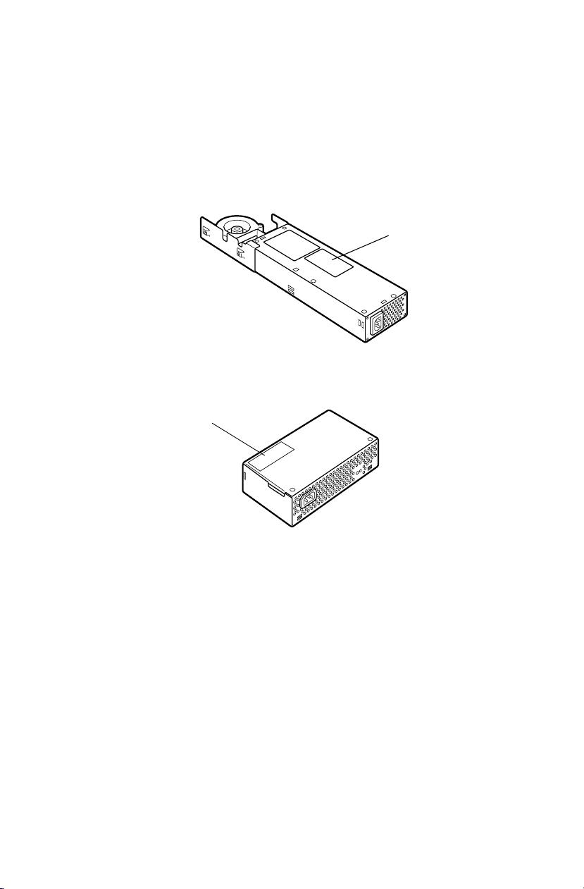
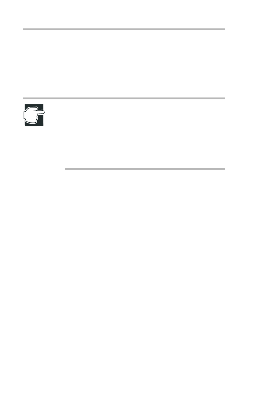
Warning Label
Some warning labels are attached to units of this equipment, as
shown below.
Read these labels carefully for safe use of this equipment:
power supply unit (System Unit)
1
2
power supply unit (External Unit)
Page 4

1.
2.
Page 5

Copyright
This guide is copyrighted by Toshiba Corporation with all rights reserved. Under
the copyright laws, this guide cannot be reproduced in any form without the prior
written permission of TOSHIBA. No patent liability is assumed, howe v er , with
respect to the use of the information contained herein.
©April 2001 by T oshiba Corporation All rights reserved.
CAUTION: This appliance contains a laser system and is
classified as a “CLASS 1 LASER PRODUCT.”
To use this model properly, read the instruction manual
carefully, and keep it for your future reference.
In case of any trouble with this model, please contact your
nearest “AUTHORIZED service station.”
To prevent direct exposure to the laser beam, do not try to
open the enclosure.
Use of controls or adjustments, or performance of procedures other than those specified in the owner’s manual,
may result in hazardous radiation exposure.
Page 6

Disclaimer
The information contained in this manual, including but not limited to any
instructions, descriptions and product specifications, is subject to change without
notice.
TOSHIB A CORPORATION (TOSHIBA) PR O VI DES NO WARRANTY
WITH REGARD TO THIS MANUAL OR ANY OTHER INFORM ATION CONTAINED HEREIN AND HEREBY EXPRESSLY DISCLAIM
ANY IMPLIED WARRANTIES OF MERCHANTABILITY OR FITNESS FOR ANY P AR T ICULAR PURPOSE WITH REGARD T O ANY
OF THE FOREGOING. TOSH IB A ASSUMES NO LIABILIT Y FOR
ANY DAMAGES INCURRED DIRECTLY OR INDIRECTLY FROM
ANY TECHNICAL OR TYPOGRAPHICAL ERR ORS OR OMI SSIONS
CONTAINED HEREIN. IN NO EVENT SHALL TOSHIBA BE LIABLE
FOR ANY INCIDENTAL, CONSEQUENTIAL, SPECIAL, OR EXEMPLARY D AMAGES, WHETHER BASED ON TORT, CONTRACT , OR
OTHER W ISE ARISIN G OUT OF OR IN CONNECTION WITH THIS
MANU AL OR ANY OTHER INFORMA TION CONTAINED HEREIN
OR THE USE THEREOF.
Trademarks
MAGNIA is a trademark of TOSHIB A Corporation.
Pentium and LANDesk are registered trademarks of Intel Corporation.
PS/2 is a trademark of International Business Machines Corporation.
MS, Microsoft, and its logos MS-DOS, Windows, and W indo ws NT ar e regis-
tered trademarks or trademarks of Microsoft Corporation.
Linux is a registered trademark or trademark of Mr. Linus T orv ald in the USA
and other countries.
Ethernet is a registered trademark of Xerox, Inc.
EZ-SCSI and SCSI Select are re gistered trademarks of Adaptec, Inc.
NetW are is a registered trademark of Nov ell Corporation.
MegaRAID is a registered trademark of Amer ican Meg atrends Inc.
U.S. Robotics, Sportster, and V. Everything are registered trademarks of 3Com
Corporation or its subsidiaries.
Other product names and trademarks belong to the individual companies
concerned.
Page 7

vii
EU Declaration of Conformity
EU Übereinstimmugserklärung
Déclaration de conformité UE
Declaración de conformidad de la UE
Dichiarazione di conformità UE
EU Försäkran om Överensstämmelse
Toshiba declares, that the product: SYU3740*/SYU3749* conforms to the following Standards:
Toshiba erklärt, daβ das Produkt: SYU3740*/SYU3749* folgenden Normen entspricht:
Toshiba déclarent que le produit cité ci-dessocus:
SYU3740*/SYU3749* est conforme aux normes suivantes:
Toshiba declaran que el producto: SYU3740*/SYU3749* cumple los sigulentes estándares:
Toshiba dichiara, che il prodotto: SYU3740*/SYU3749* è conforme alle seguenti norme:
Toshiba intygar att produkten: SYU3740*/SYU3749* överensstämmer med följande normer:
Supplementary Information: “The product complies with the requirements of the Low V oltage
Weitere Informationen: “Das Produkt entspricht den Anforderungen der Niederspan-
Informations complémentaires: “Ce produit est conforme aux exigences de la directive sur les
Información complementaria: “El Producto cumple los requistos de baja tensión de la Directiva
Ulteriori informazioni: “Il prodotto é conforme ai requisiti della direttiv a sulla bassa ten-
Ytterligare information: “Produkten uppfyller kraven enligt lägspänningsdirektiv er
This product is carrying the CE-Mark in accordance with the related European Directives. Responsible for CE-Marking is Toshiba Europe GmbH, Hammfelddamm 8, 41460 Neuss, Germany.
Notice to user of EN55022
c
Directive 73/23/EEC and the EMC Directive 89/336/EEC .”
nungs-Richtlinie 73/23/EG und der EMC-Richtlinie 89/336/EG.”
basses tensions 73/23/CEE et de la directive EMC 89/336/CEE.”
73/23/CEE y la Directiva EMC 89/336/CEE.”
sione 73/23/EG e la direttiva EMC 89/336/EG.”
73/23/EEC och EMC-direktiv 89/336/EEC.”
WARNING: This is a Class A product. In a domestic environment, this product may cause radio interference in
which case the user may be required to take adequate
measures.
Page 8

Page 9

Introduction
Key features of the MA GNIA Z300
Compact chassis of 2U 1/2 widths
c
Installation flexibilit y (Rack and Micro Tower)
c
Up to two Pentium III processors (866 MHz, 1 GHz)
c
One 64bit/66MHz PCI slot
c
Main memory expandable to a maximum of 3 GB
c
24-speed CD-ROM dri ve as standard
c
Up to two 76 GB hard disk drives (IDE)
c
IDE RAID as standard (RAID 0 and 1)
c
Hot-swap hard disk drives
c
Ultra 160 SCSI IF
c
2 LAN ports (100BASE-TX) provided as standard, ALB
c
(Adaptive Line Balance) and AFT (Adapti v e Fault Tolerance)
compatible
Wireless LAN (IEEE802.11b) card (option) can be mounted
c
ix
Page 10

x
Remote management mechanism via network (power ON/
c
OFF , reboot provided as standard)
Server setup assist softw are “Toshiba Server Setup Tool”
c
Integrated server operat ion management software HarnessEye/
c
web
Flexibility of system conf iguration with ext ernal units (Exter-
c
nal Hard Drive Unit Z1 and External De vice Bay Unit Z1)
NOTE: The MAGNIA Z300 meets the FCC regulations for
a Class A digital device, suitable for use in a business
installation. There is a possibility of radio interference when
using the MAGNIA Z300 in a home environment.
About this guide
This guide introduces the features of the MA GNIA Z300 and
explains how to set up, conf igure, and maintain the serv er.
Before using the MAGNIA Z300 serv er , please read through the
guide to gain an overall unders tanding of operating procedures
and safety precautions .
Page 11

Safety cautions
Before attempting to use your Toshiba MAGNIA Series Server , all
safety instructions must be read carefully and fully understood.
This manual contains the safety instructions that must be observed
in order to avoid potent ial hazards that could result in personal
injuries or damage to the rack or the units installed in them. The
safety instructions hav e been classif ied according to the seriousness of the risk, and the following icons highlight these
instructions as follows:
DANGER: This icon indicates the existence of a hazard
that could result in death or serious bodily injury if the
safety instruction is not observed.
CAUTION: This icon indicates the existence of a hazard
that could result in damage to equipment or property if the
safety instruction is not observed.
xi
WARNING: This icon indicates the existence of a hazard
that could result in bodily injury if the safety instruction is
not observed.
NOTE: This icon indicates information that relates to the
safe operation of the equipment or related items.
When installing any unit or m aintaining the system, it is e xtremely
important that the basic safety practices are follo wed .
Page 12

xii
Other icons used
Additional icons highlight other helpful or educational
information:
TECHNICAL NOTE: This icon provides technical information about the server which, while not essential, may be of
interest to you.
HINT: This icon denotes helpful hints and tips.
DEFINITION: This icon indicates the definition of a term
used in the text.
Documentation
The server comes with the follo wing documentation:
The MAGN IA
c
CD-ROM) contains the technica l information about ho w the
server works.
Harness Eye/web User’s Guide (on the Documentation CD-
c
ROM) contains Harness Eye/web sett ings and operation methods. Harness Eye/web runs on Windo ws NT
4.0, Windo ws
The Toshiba Server Setup Tool User’s Guide (on the Docu-
c
mentation CD-ROM) contains inst ructions for setting up and
optimizing installation of Microsoft
®
ell
NetWare®. This also includes the installation of Toshiba-
authorized option drivers .
The Safety Instruction Guide for Toshiba Servers contains
c
safety information.
Warranty information Booklet.
c
™
Z300 User’s Guide ( on the Documentation
®
Server Version
®
2000 Server and Linux.
®
Windows NT® or Nov-
Page 13

Read Me First Addendum
c
Software License Agreement
c
Service options
T oshi ba of fers a full line of service opti ons bui lt around its warranty programs. See the warranty and service material included
with the server for regist ration information.
Maintenance contracts
Periodic maintenance and inspection is essential for keepi ng the
server fully operational and assuring it s safe use. Toshiba recommends taking out a maintenance contract for this purpose.
xiii
Page 14

Page 15

Contents
Chapter 1: Getting Started............................................................................. 2
Checking the items included with the server............................................ 2
Mounting optional internal devices............................................................ 4
Environmental considerations.................................................................... 5
Micro Tower Type/Rack Type ............................................................... 5
Micro Tower Type................................................................................... 7
Rack Type................................................................................................ 8
Power requirements.................................................................................... 9
Front view (with the front panel closed) ................................................. 10
Key lock................................................................................................. 10
Front view (with the front panel opened) ................................................ 11
(1) Front panel .......................................................................................11
(2) Operation buttons .......................................................................... 12
(3) System status indicators ............................................................... 14
(4) Front panel display ......................................................................... 16
(5) Card slot .......................................................................................... 18
(6) USB1 connector ............................................................................. 18
(7) USB2 connector ............................................................................. 18
(8) Device bay ...................................................................................... 18
(9) HDD/LAN status indicators ........................................................... 19
Page 16

xvi
Rear view................................................................................................... 22
(1) AC connector .................................................................................. 22
(2) Security Loop .................................................................................. 22
I/O connectors ...................................................................................... 23
Expansion slot ...................................................................................... 24
LAN status indicators........................................................................... 24
Inside the server........................................................................................ 25
(1) Motherboard ................................................................................... 25
(2) SCSI riser card ............................................................................... 25
(3) Cooling fans.................................................................................... 26
(4) CPU sockets................................................................................... 26
(5) Memory slots .................................................................................. 26
(6) Expansion slot ................................................................................ 26
(7) IDE HDD cage................................................................................ 26
(8) Board for wireless card.................................................................. 26
Connecting peripheral devices................................................................ 26
How to connect peripheral devices ................................................... 26
Floppy disk drive .................................................................................. 29
Maintenance.............................................................................................. 30
Maintenance of the server .................................................................. 30
Maintenance of the keyboard............................................................. 30
Maintenance of the display unit.......................................................... 30
Connecting the power cable.................................................................... 31
Switching on the server............................................................................ 33
Turning on the server in the usual process....................................... 33
Turning on the server by the “Remote Management” function...... 34
POST (Power On Self-Test).................................................................... 34
Starting up the system.............................................................................. 35
Starting up with the floppy disk........................................................... 35
Starting up by the hard disk drive unit (in the case the OS has been
installed) ................................................................................................ 36
Starting up by the CD-ROM ............................................................... 37
BIOS setup ................................................................................................ 37
Making a floppy disk................................................................................. 38
How to make a backup floppy disk.................................................... 38
Page 17

xvii
Setup of system configuration................................................................. 39
BIOS setup utility.................................................................................. 39
SCSI utility............................................................................................. 39
IDE RAID Setup utility ......................................................................... 39
Setup of disk array (RAID)....................................................................... 40
Installing software ..................................................................................... 41
Switching off the server............................................................................ 42
Normal shutdown ................................................................................ 42
Using the automatic shutdown function............................................ 42
Notes on using of the automatic shutdown function ....................... 44
Abnormal system shutdown .............................................................. 46
Chapter 2: Installing and Removing Hardware......................................... 48
Before starting operation.......................................................................... 48
Before starting operation..................................................................... 49
Installing/removing an optional device .............................................. 52
Removing and replacing the server panels .......................................... 54
Replacing the top panels (for Micro Tower Types).......................... 55
Removing/replacing the top panel (for Rack Types)....................... 55
When using a Rack Type................................................................... 56
Power Supply Unit.................................................................................... 69
Removing the power supply unit....................................................... 69
Installing the power supply unit .......................................................... 70
Memory module........................................................................................ 72
Installing an additional memory module ........................................... 74
Removing a memory module ............................................................ 77
CPU module.............................................................................................. 78
Installing the CPU module.................................................................. 79
Replacing the CPU module ............................................................... 87
Internal battery........................................................................................... 94
Replacing the internal battery............................................................. 95
Hard Disk Drive (HDD) –IDE HDD– ...................................................... 98
Installing the hard disk drive ............................................................... 98
Replacing a hard disk drive during operation................................. 100
Expansion cards..................................................................................... 103
Restrictions on PCI expansion cards.............................................. 103
Installing the SCSI riser card ............................................................ 104
Page 18

xviii
Chapter 3: External Unit Setup ................................................................. 110
Types of External Unit ............................................................................ 110
Front view of the External Hard Drive Unit Z1 (with the front panel
closed)...................................................................................................... 111
Key lock............................................................................................... 111
Front view of the External Hard Drive Unit Z1 (with the front panel
opened).................................................................................................... 112
(1) Front panel.................................................................................... 112
(2) Power button................................................................................. 113
(3) System status indicators ............................................................. 114
(4) HDD status indicators.................................................................. 115
Rear view of the External Hard Drive Unit Z1 ..................................... 117
AC power connector.......................................................................... 117
I/O connectors .................................................................................... 117
(1) External Unit control connector IN/OUT ()................................ 117
(2) SCSI connector ()......................................................................... 118
Installing and Removing Hard Disk Drive (HDD)
-SCSI HDD-............................................................................................. 118
Installing the hard disk drive.............................................................. 118
Replacing a hard disk drive during operation................................. 121
Setup of disk array (RAID)..................................................................... 125
Front view of the External Device Bay Unit Z1 (with the front panel
closed)...................................................................................................... 126
Key lock............................................................................................... 126
Front view of the External Device Bay Unit Z1 (with the front panel
opened).................................................................................................... 127
(1) Front panel.................................................................................... 127
(2) Power button................................................................................. 128
(3) System status indicators ............................................................. 129
Rear view of the External Device Bay Unit Z1.................................... 130
AC power connector.......................................................................... 130
I/O connectors .................................................................................... 130
(1) External Unit control connector IN/OUT ()................................ 130
(2) SCSI connector ()......................................................................... 131
Installing SCSI device............................................................................. 131
Terminator........................................................................................... 131
Page 19

xix
SCSI ID............................................................................................... 131
How to Connect an External Unit ......................................................... 136
Chapter 4: System Configuration Setup................................................. 140
BIOS setup utility..................................................................................... 140
Starting the setup utility ..................................................................... 141
Menu screen ...................................................................................... 142
Changing BIOS Settings .................................................................. 143
BIOS Settings..................................................................................... 143
SCSI Utility............................................................................................... 152
Starting the SCSI Utility..................................................................... 153
Menu configuration............................................................................ 154
SCSI Utility Keyboard Commands.................................................. 154
Changing SCSI Device Settings ..................................................... 155
Setting Devices .................................................................................. 155
Remote Management and Front Panel Display Setup Tool............. 158
How to start up and operate the setup tool .................................... 158
Configuring MegaRAID IDE.................................................................. 162
Configuring MegaRAID IDE............................................................. 162
Using the MegaRAID IDE Setup Utility........................................... 165
Switch Windows (TAB)..................................................................... 167
Auto Configure Stripe (F1) ............................................................... 167
Auto Configure Mirror (F2) ............................................................... 167
Create Array (F4)............................................................................... 168
Delete Array (F5) .............................................................................. 171
Restore Old Configuration (F6) ....................................................... 171
Edit Options (F7)................................................................................ 171
Save and Exit (F10) .......................................................................... 172
Chapter 5: Installing Software .................................................................. 174
Windows NT® Server 4.0 ..................................................................... 174
Setting the motherboard................................................................... 174
Windows® 2000 Server ........................................................................ 175
Setting the motherboard................................................................... 175
Creating driver disks.......................................................................... 175
Selecting the disk driver.................................................................... 176
Installing the display driver................................................................ 178
Page 20

xx
Installing the network driver .............................................................. 178
Procedure after installation of the Windows 2000 Server ............ 179
NetWare................................................................................................... 180
Before installing the NetWare........................................................... 180
For installing NetWare 5.1 manually................................................ 182
For installing the NetWare 4.2 manually......................................... 188
Procedure after installation of the NetWare.................................... 192
HarnessEye/web .................................................................................... 193
Installing and operation ..................................................................... 193
AFT, ALB and IPSec functions.............................................................. 194
What are the AFT and ALB functions?........................................... 194
When using on Windows NT 4.0..................................................... 194
When using on Windows 2000:....................................................... 197
When using NetWare:....................................................................... 203
Auto-shutdown function ......................................................................... 204
Setting the auto-shutdown function................................................. 204
Canceling the auto-shutdown function............................................ 204
Chapter 6: Troubleshooting...................................................................... 206
Troubleshooting ...................................................................................... 206
You can hear abnormal noise or smell foul odours, and hear a
continuous buzzer.............................................................................. 206
Nothing happens if you press the power switch. Or, nothing appears
on screen even though you can hear the server running.................... 207
Characters are distorted or not displayed properly........................ 208
The system status indicators and disk status indicators turn on
abnormally .......................................................................................... 208
The disk and STS indicators light and flash amber....................... 209
The fault indicator lights amber ........................................................ 209
The FDD indicator does not light ..................................................... 209
An error is displayed during POST operation, or POST stops
midway................................................................................................ 210
Loading of RAID controller BIOS stops midway............................ 210
Cannot install the OS......................................................................... 211
The OS does not boot, or the OS bootup stops midway ............. 211
Windows NT/2000 is locked or cannot be used............................ 212
Trouble information or error log still remains in the server monitor
function software and other software .............................................. 212
Page 21

xxi
The power button does not function after abortion........................ 213
The internal clock does not keep precise time............................... 213
Trouble with Application Software........................................................ 213
Remedy When Windows NT/2000 is Usable .................................... 214
Remedy When Windows NT/2000 is Unusable................................ 215
Appendix A: Specifications....................................................................... 218
System Unit ........................................................................................ 218
External Hard Drive Unit Z1 ............................................................. 220
External Device Bay Unit Z1 ............................................................ 221
Appendix B: Interfaces.............................................................................. 224
RGB interface..................................................................................... 224
RGB interface synchronizing signals .............................................. 225
Serial interface.................................................................................... 226
Keyboard/mouse interface ............................................................... 227
LAN-1/2 interface............................................................................... 228
USB-1/2 interface .............................................................................. 228
Expansion slots (64bit/66MHz PCI slot) ......................................... 229
Appendix C: Switch Setting...................................................................... 234
Hardware setup information ............................................................. 234
Recovery Boot ................................................................................... 235
Appendix D: Trouble Information............................................................. 240
Appendix E: Unit Logs .............................................................................. 246
Unit logs .............................................................................................. 246
Basic system configuration............................................................... 247
CPUs................................................................................................... 247
Memories............................................................................................ 247
IDE Hard disk drives.......................................................................... 248
SCSI units........................................................................................... 248
Expansion cards ................................................................................ 248
Expansion units.................................................................................. 249
Other optional items .......................................................................... 249
Page 22

xxii
Page 23

Chapter
Checking the items incl uded with the serv er .......... ........... ....... 2
Mounting opt ional in ternal de vices .................. .......... ....... ........ . 4
Environmental considerations ..................................................... 5
Power requirements ...................................................................... 9
Front vie w (with the front panel closed) ............ .......... ........... . 10
Front vie w (with the front panel opened) .............. ........... ....... 11
Rear view ..................................................................................... 22
Inside the server .......................................................................... 25
Maintenance .. .. .. .. .. .. .. .. .. .. .. .. .. .. .. ... .. .. .. .. .. .. .. .. .. .. .. .. .. .. .. .. .. .. ... .. .. .... 30
Connecting the power cable ...................................................... 31
Switching on the server .............................................................. 33
POST (Power On Self-Test) ...................................................... 34
Starting up the system ................................................................ 35
BIOS setup .................................................................................. 37
Making a floppy disk ................................................................. 38
Setup of system configuration ................................................... 39
Setup of disk array (RAID) ....................................................... 40
Installing software ....................................................................... 41
Switching off the server ............................................................. 42
1
Page 24

Getting Started
This chapter describes ho w to set up the server and to hav e it ready
for use.
Checking the items included with the server
Check the items in the package according to the accompanying
Read Me First Addendum.
If any of the items is missing or damaged, please contact your
T oshi ba dealer as soon as possible.
2
Page 25

Getting Started
Checking the items included with the server
NOTE: The Read Me First Addendum provides a listing of all
standard accessories and their respective quantities.
If you purchased the server together with an optional internal
device, the optional device will also be incorporated with the
standard accessories listed. However, in such a case it is
possible that the quantities of some accessories, e.g., brackets, do not agree with those specified on the list, this is
because they have already been used to fix the optional internal device.
If in contrast an expansion slot panel etc. has been removed
from the server in order to install an optional device instead,
the expansion slot panel removed comes with the server as
an accessory.
3
Page 26

Getting Started
4
Mounting optional internal devices
Mounting optional internal devices
If you have purchased an optional internal de vice together with the
server , install it befor e setting up the serv er.
See “Installing/removing an optional de vice” on page52.
If you find it dif f icult to inst all an optional device yourself, always
ask an authorized MAGNIA service pro vider to do it for you.
Page 27

Environmental considerations
Environmental considerations
Micro Tower Type/Rack Type
Install the server in a clean, dust- free and well-ventilated place .
c
Install the server on a le vel and steady surface.
c
Never install the server upside down.
c
Ensure the following when installing the serv er:
c
- Do not expose to direct sunlight
- Do not install in locations susceptible to vibration or shock.
- Do not install near apparatus which has a strong magnetic
force or produces radio noise, (e.g. radio set, TV set, large
motor or loudspeaker etc.).
- Do not install in locations susceptible to large tem perature or
humidity changes, or near an air-conditioner air v ent, cooling
fan, heater or heat source
Getting Started
5
- Do not install in location where liquids or corrosi ve chemicals are stored.
WARNING: If any foreign matter, including water, has gone
into the server, perform the shutdown steps immediately, turn
off the power button, and unplug the power cable from the
wall outlet.
Operating the server as it is might cause a fire or an electric
shock. If such trouble occurs, ask an authorized MAGNIA
service provider to inspect your server.
NOTE: Do not turn the server back on until is has completely
dried out.
If the server does not run normally after being turned back on,
contact an authorized MAGNIA service provider.
Page 28
6
Getting Started
Environmental considerations
Only operate the server under the follo wing conditions:
c
- Ambient temperature:
50 to 95°F (10 to 35°C) (Micro T ower Type)
50 to 89°F (10 to 32°C) (Rack T ype)
- Ambient humidity: 30 to 80%Rh (No condensation)
NOTE: To avoid condensation when the room temperature is
too high or too low, do not start your server for about one hour
after the room temperature has fallen within a range of 50 to
95°F (10 to 35° C), or 50 to 89 °F (10 to 32° C) if your server is
a Rack Type.
Keep the server free from condensation during use and storage.
Page 29

Micro Tower Type
Leave enough space around the serv er for maintenance and
ventilation.
12 inches
(30cm) or
more
Getting Started
Environmental considerations
8 inches (20cm) or more
7
Minimum clearances r equir ed for horizontal inst allation
12 inches (30cm)
or more
Minimum clearances r equir ed for vertical ins tallation
8 inches (20cm) or more
Page 30

8
Rack Type
Getting Started
Environmental considerations
Up to four System Units and External Units can be installed when
stacked horizontally.
Use the optional Toshiba rack and rack mount kit to install a
c
Rack T ype.
Leave a clearance of more than 24 inches (60 cm) before and
c
behind the rack to ensure good ventilation around the serv er.
24 inches (60cm) or more
24 inches (60cm) or more
Minimum clearances for installation
Page 31

Power requirements
Before plugging the power cable in to a wall outl et (especially if
your server is a Rack Type), ensure the following: make sure that
the capacity of the power supply (current ra ting of the wall outlet)
and that of the over -current protector (curre nt rating of the circuit
breaker) are correct.
Whenever you ha ve a question about wiring etc., al ways consult
an authorized MAGNIA service pro vider.
The power rating of the serve r is 160W.
T o ensure the serv er is securely grounded, alw ays use the po wer
cable supplied with the server.
For wiring in the rack, use an opti onal AC multi-tap r ecommended
by Toshiba.
WARNING: Do not use any power cable other than the one
supplied with the server.
The use of an improper power cable may result in a fire.
Getting Started
Power requirements
9
Do not use any optional part other than a genuine Toshiba
parts or those parts recommended by Toshiba.
The use of parts other than those recommended by Toshiba
may result in a fire. For optionally-available parts and
devices, contact an authorized MAGNIA service provider.
NOTE: For both Micro Tower Type and Rack Type, it is recommended to use an uninterruptible power supply (UPS).
Page 32

Getting Started
10
F r ont vie w (with the front panel closed)
Front view (with the front panel closed)
Key lock
CD-ROM drive
Power indicator ( )
Disk indicator ( )
Auto-shutdown indicator ( )
Fault indicator ( )
Front panel display
Display change button
USB 1 connector
USB 2 connector
Key lock
System
status
indicator
F r ont vie w with the fr ont panel closed
The front panel can be locked in two ways: full access and no
access, depending on the direction of the keyhole.
Full access
No access
Key lock
Page 33

Getting Started
F ront view (with the front panel opened)
Front view (with the front panel opened)
(4) System status indicators
(2) CD-ROM drive
(9) Device
bay
(10) HDD/LAN
status
indicators
(1) Front panel
F r ont vie w of the Micr o Tower T ype
(1) Front panel
(3) Operation buttons
11
(5) Front panel
display
(6) Card slot
(7) USB 1
connector
(8) USB 2
connector
The front panel can be opened by releasing the ke y lock, and pushing its upper center (::) and detached by unhooking its hinges.
Opening the front panel
Page 34

Getting Started
12
F r ont vie w (with the front panel opened)
Removing the fr ont panel
(2) Operation buttons
The server has 4 operation buttons on the front panel.
Power/sleep button ( )
Reset button ( )
NMI button ( )
Display change button ( )
NMI
Operation buttons
Page 35

Getting Started
F ront view (with the front panel opened)
13
Power/
sleep
button
Reset
button
NMI
button
Display
change
button
Press this button to turn on or off the server.
ON ... Pressing the button once causes the server
to start up.
OFF ... Enabling the auto-shutdown function: If
you hold your finger cont inuously for four seconds or more and take your finger away, the OS
is shut down and the power supply is tur ned off .
If you take your finger a way within four seconds,
the power is not turned of f.
... Disabling the auto-shutdown function: If
you press once, and take your finger away, the
power is turned of f.
Sleep ... On OSs that support the power sav e
mode, releasing this button within 4 seconds
switches between the power sav e mode (sleep
mode, hibernation mode) and the regular
mode.*1
Press this button to reset the serv er. Use a fine
wire etc. to press this button.
This button is provided e xclusi vely for the autho-
NMI
rized MAGNIA service pro vider.
Press this button to change the information on
front panel display .
*1: The sleep mode is operational only when an ACPI-supporting OS (operating
system such as Windows 2000) is installed on the system.
See the instruction manual for your OS.
CAUTION: Do not perform a reset that turns the power off
while the FDD indicator, CD-ROM indicator and disk indicator
are lit. You may lose the data.
The way to switch on and off the serv er v aries depending on the
OS installed on it.
See “Switching on the server” on page 33 and “Switching off the
server” on page 42.
Page 36

Getting Started
14
F r ont vie w (with the front panel opened)
(3) System status indicators
Your server has 4 operating status indicators on the front panel.
Power indicator ( )
System status indicators
Disk indicator ( )
Auto-shutdown indicator ( )
Fault indicator ( )
Indicator Status Meaning
Power Off Out of operation (AC po wer not supplied)
Lit amber Out of operation (AC power supplied)
Lit green In operation
Disk Off Out of operation
Flashing
green
Built-in disk driv e in operation
Page 37

Getting Started
F ront view (with the front panel opened)
Indicator Status Meaning
15
Auto
Shutdown
Fault Off One of the following modes:
Off Out of operation
Lit green Auto Shutdown function is enabled
Auto Shutdown function is ready to start when power
switch is turned off
Lit amber Auto Shutdown function is out of order
- Auto Shutdown is used on W indows NT, Windows
2000 or Linux, and the Auto Shutdown function is not
installed
- Auto Shutdown is used on W indows NT, Windows
2000 or Linux, the Auto Shutdown function is
installed, and set to Disabled (*1)
- Windo ws NT, Windows 2000 or Linux is booting
- An operating system other than W indo ws NT or W indows 2000 or Linux is running
- Out of operation
- The cooling fan, power supply unit and disk are in the
normal state.
Flashing
amber
- The cooling fan or/and po wer supply unit or/and disk
is faulty. (The failure part will be displayed on front
panel display.)
*1: Sets the Auto Shutdo wn function to Disabled/Enabled.
See “ Auto-shutdown function” on page 204.
NOTE: If any trouble has occurred, contact an authorized
MAGNIA service provider.
Page 38

Getting Started
16
F r ont vie w (with the front panel opened)
(4) Front panel display
This server is equipped with a 16-digit/2-line front panel dis play.
The following information is displayed on this panel :
1. System configuration
2. User messages
3. Trouble information
4. Bootup/shutdown messages
1. System configuration
When user messages are not set, the system configuration
(mounted CPU, number of CPUs, number of External Hard
Drive Unit Z1, number of External De vice Bay Unit Z1) is displayed (scroll display).
Example
MAGNIA Z300 TOSHIBA Compact Server
Pentium III xm, ExDisk xn, ExBay xi
PentiumIII xm : m=number of CPUs
ExDisk xn : n=number of External Hard Drive Unit Z1s
ExBay xi : i=number of External Device Bay Unit Z1s
The number of unit is reflected after power is on.
2. User messages
In HarnessEye/web, there are two screens for user messages:
“Panel display 1” and “Panel display 2”. One of these is dis played. Messages can be set by “Panel displa y 1”. Warning
notices are displayed by “Panel dis play 2”.
Up to 40 1-byte characters can be set per line.
When user messages exceed 16 characters, the display can be
scrolled to display all of the message.
User messages can be switched alternately by the display
change button.
Page 39

Getting Started
F ront view (with the front panel opened)
T w o messages can be set b y Remote Management and Front
Panel Display Setup Tool in the case of a Netware environment.
See “System Configuration Setup” on page 140.
or the
“Harness Eye/web User’ s Guide” (on the Documentation CD-
ROM)
3. Trouble information
When a problem occurs, the details of the problem and the
location where the problem occurred are displayed flashing on
the panel.
When the trouble information exceeds 16 characters, the display can be scrolled t o display all the infor mation.
Display and meaning
See “ AppendixD” on page239.
17
Display example
ALARM (22)
CPU1 thermal error.
Holding down the display change butt on for at least four seconds displays the user message or system configuration. Also,
holding down the b utton for at least f our seconds with the user
message or system configuration displayed displays the trouble
information.
4. Bootup/shutdown messages
The following message is displayed blinking when the serv er
is booted up and shut down. (scroll display)
At bootup
System booting. Please wait a moment.
POST code ($--,--,--,--,--,--,--)
Page 40

Getting Started
18
F r ont vie w (with the front panel opened)
At shutdown by auto SD
Now shutting down system.
Holding down the display change butt on for at least four seconds displays the user message or system configuration.
(5) Card slot
The card slot accepts an optional wireless LAN card.
(6) USB1 connector
Used to connect a USB de vice .
(7) USB2 connector
Used to connect a USB de vice .
(8) Device bay
Used to install up to two hard disk driv es
Page 41

F ront view (with the front panel opened)
(9) HDD/LAN status indicators
When the device bay accomodates hard disk dri ves, the stat us of
each hard disk drive is indicat ed by the HDD status indicators
placed below the de vice bay.
The network status of the LAN1 and LAN2 connectors are displayed on the LAN status indicators.
HDD 2
HDD 1
Getting Started
19
ACT 1
LNK 1
ACT 2
LNK 2
Indicator Status Meaning
ACT 1
(LAN1)
LNK 1
(LAN1)
ACT 2
(LAN2)
Out Data transfer (10Mbps or 100Mbps) is not
Lit
green
Out Network communications (10Mbps or
Lit
green
Out Data transfer (10Mbps or 100Mbps) is not
Lit Data transfer (10Mbps or 100Mbps) is in
STS 2
PWR 2
STS 1
PWR 1
in progress on network.
Data transfer (10Mbps or 100Mbps) is in
progress on network.
100Mbps) is not possible.
Network communications (10Mbps or
100Mbps) is possible.
in progress on network.
progress on network.
Page 42

20
Getting Started
F r ont vie w (with the front panel opened)
Indicator Status Meaning
LNK 2
(LAN2)
STS 1
(HDD1)
PWR 1
(HDD1)
STS 2
(HDD2)
Out Network communications (10Mbps or
100Mbps) is not possible.
Lit Network communications (10Mbps or
100Mbps) is possible.
Off No hard disk drive is inst alled.
No data is being read or written.
Lit green Data is being read or written.
Lit
amber
Flashing
amber
Off No hard disk drive is inst alled.
Lit green Power is supplied to the hard disk dri ve.
Off No hard disk drive is inst alled.
Lit green Data is being read or written.
Lit
amber
Trouble has occurred.
The disk array is being rebuilt.
No power is supplied t o the hard disk driv e.
No data is being read or written.
Trouble has occurred.
PWR 2
(HDD2)
Flashing
amber
Off No hard disk drive is inst alled.
Lit green Power is supplied to the hard disk dri ve.
The disk array is being rebuilt.
No power is supplied t o the hard disk driv e.
Page 43

Getting Started
F ront view (with the front panel opened)
NOTE: When a STS indicator is lit amber, the corresponding
hard disk drive may be faulty. If it is found to be defective,
replace it. If your system is configured in redundancy
(RAID1), you can replace the faulty drive without interrupting
the system operation.
Shock and vibration might damage hard disk drives, causing
the loss or corruption of the data and programs recorded on
them. So always handle them carefully.
Installing and replacing a hard disk drive requires special
techniques and knowledge. So instead of installing or replacing it yourself, ask an authorized MAGNIA service provider
for assistance.
An error performed during installation or replacement, especially when the system is running, might result in a system
failure and/or the corruption or loss of important data and programs.
21
Keep hard disk drives free from shock and vibration, especially when they are on. Even if the STS indicator is off, its
magnetic head remains in the data area and, if a shock is
given, it might destruct the data area.
When the server is switched off, the magnetic head of each
hard disk drive automatically retracts. Note that it takes about
30 seconds for a hard disk drive to stop completely.
Page 44

Getting Started
22
Rear view
Rear view
(1) AC connector
Rear view of the server
(1) AC connector
Used to connect the AC po wer cable.
See “Connecting the power cable” on page 31.
(2) Security Loop
(2)
Security Loop
It is possible to attach chains, etc. to pre vent the ser ver from theft.
Security Loop
Page 45

I/O connectors
Plug the cables of peripheral devices into their respecti ve I/O ports.
(1) Mouse
connector ( )
Getting Started
Rear view
(8) SCSI connector ( )
(7) External unit control connector ( )
23
(2) Keyboard
connector ( )
I/O connectors
(1) Mouse connector ( )
(2) Keyboard connector ( )
(3) LAN 1 connector ( 1)
(4) LAN 2 connector ( 2)
(5) RGB connector ( )
(6) Serial connector ( )
(7) External unit control connector ( )
(4) LAN 2 connector ( 2)
(3) LAN 1 connector ( 1)
(5) RGB connector ( )
(6) Serial connector ( )
Used to connect the PS/2 mouse.
Used to connect the PS/2 keyboard.
Ether
Used to connect a 100BASE-T or 10B ASE-T .
Ether
Used to connect a 100BASE-T or 10B ASE-T .
Used to connect a display .
Used to connect an RS-232C-compliant device.
Used to connect the external unit.
Ether
Ether
(8) SCSI connector ( )
Used to connect the SCSI cable.
See “How to connect peripheral de vices” on page26.
Page 46

Getting Started
24
Rear view
Expansion slot
The server has 1 expansion slot for e xpansion cards: 64 bit/66
MHz PCI slot.
LAN status indicators
Link
Link
Indicator Status Meaning
Link Lit green Connected successfully
Off Network cable not connected or incor-
rectly connected
Activity Lit green Data being transferred
Off No active
Activity
LAN 2 connector
LAN 1 connector
Activity
Page 47

Inside the server
Getting Started
Inside the server
25
(7) IDE HDD Cage
(2) SCSI riser card
(8)
Board for wireless card
Inside the server
(1) Motherboard
The main board can contain 2 CPU modules and 3 memory modules at the maximum.
(4) CPU sockets
(6) Expansion slot
(3) Cooling fans
(1) Motherboard
(5) Memory slots
(2) SCSI riser card
The SCSI riser card has 1 PCI expansion slot (half length cards
only).
Page 48

Getting Started
26
Connecting peripheral de vices
(3) Cooling fans
The server contains two cooling fa ns.
(4) CPU sockets
Used to mount CPU modules.
See “CPU module” on page 78.
(5) Memory slots
Used to mount up to 3 memory modules to expand the server’ s
RAM (Random Access Memory).
See “Memory module” on page 72.
(6) Expansion slot
Used to mount expansion cards. A 64 bit/66 MHz PCI card of c ard
length 194 mm or less can be added on to the riser card. The slot is
compliant with PCI 2.2 standard.
See “Expansion cards” on page 103.
(7) IDE HDD cage
The IDE HDD cage supports up to two hot-swap hard disk driv es.
(8) Board for wireless card
The board for wireless card can contain 1 wireless LAN card.
Connecting peripheral devices
How to connect peripheral devices
There are USB connectors for connecting USB devices such as
FDD and so on, on the front of the server . And there are I/O connectors for connecting peripheral devices such as a k e yboard,
mouse, display and so on, on the back of the server . Properl y connect the devices to the connectors before turning on the ser ver.
Page 49

Getting Started
Connecting peripheral devices
Connect peripheral devices to the serv er , accor ding to the follo wing procedure:
NOTE: USB devices can be connected while the server is
running.
1 Make sure that all the power b uttons of the server and e xternal
units are turned off.
2 If the power cables of the serv er and exter nal units are con-
nected to an AC outlet, pull the pl ug of the power cable out of
the AC outlet.
3 Connect each of the peripheral devices to a proper connector
on the server with an interface cable.
Insert the connectors to the correct ports on the server.
Use the serial conv erter cable on the ser ial interf ace.
27
Connecting peripheral devices (Front view)
Page 50

28
Getting Started
Connecting peripheral de vices
Connecting peripheral devices (Rear vie w)
4 If a connector is provided with scre ws for securing connection,
tighten the screws without f ail.
5 After making sure that all the peripheral units are properly con-
nected, plug the power cables of the server and peripher al units
into AC outlets.
WARNING: When connecting optional units, be sure to use
genuine Toshiba parts or those recommended by Toshiba. If
something other is connected to the server, it may cause an
outbreak of fire.
For details of optional parts, contact an authorized MAGNIA
service provider.
Page 51

NOTE: When connecting and disconnecting an interface
cable, be sure to hold the cable connector.
Some articles and interface cables of other brands cannot be
connected to this server as external units and connecting
cables. Before purchasing a peripheral unit, ask the manufacturer or sales office of the article about its compatibility to this
server. When connecting peripheral units, see to instructions
of respective units together with this manual.
Floppy disk drive
The floppy disk driv e (FDD) supports two floppy- disk formats:
3.5“ 2HD (1.44 MB) and 3.5” 2DD (720 KB).
NOTE: The FDD indicator is lit while data is being read or
written. When it is lit, do not turn off the server, nor press the
eject button, nor reset the server. Otherwise, data recorded
on the floppy disk might be lost or corrupted.
Getting Started
Connecting peripheral devices
29
After using the floppy disk drive, always remove the floppy
disk from it.
Page 52

Getting Started
30
Maintenance
Maintenance
Maintenance of the server
If the outside of the server is dirty or stained, gently wipe it off
with a soft cloth. If it is sev erely dirty, moisten the soft cloth with
water and lightly wipe off the dirt..
If benzene, thinner or a similar substances is used for cleaning or a
chemical such as an insecticide is applied onto the surface, the
server may be deformed or discolored.
Do not subject the server to a strong shock or vibration. If the
server is dropped or knocked against other objects, it may cause a
failure or malfunction of the serv e r.
Maintenance of the keyboard
If dust has accumulated in crevices in the ke yboard, it may cause
malfunction of the keyboard. Clean the ke yboard according to the
following procedure:
1 Shut down the server to cut of f the po wer supply to the k e y-
board.
2 Remove dust between the keys using a v ac uum cleaner . 3 Clean every k ey with a soft dry cloth.
NOTE: Be very careful not to spill liquid on the keyboard.
Maintenance of the display unit
Dust accumulates on the display screen because of static electricity . Wipe down the display screen with dry soft cloth re gularly.
Don’t use wet cloth for cleaning.
Page 53

Connecting the power cable
Connecting the power cable
NOTE: Use of an uninterruptible power supply (UPS) is recommended to avoid losing data because of unexpected shutdown or power failure.
This product is also designed for IT power system with
phase-to-phase voltage 230V.
After connection of peripheral devices is complete, connect the
power cable to this serv er follo wing the procedure mentioned
below.
1 Connect the power cable to the connector on the back of the
server .
Getting Started
31
Connecting the power cable
2 Plug the power cable into an A C outlet or the po wer output
connector of an uninterruptible power supply (UPS).
Page 54

32
Getting Started
Connecting the power cable
WARNING: Be sure to use the power cable supplied with the
server. Using another power cable may cause an outbreak of
fire.
Plug the power cable into an AC outlet with a ground line. If
the power cable is plugged into an unspecified AC outlet, it
may cause an outbreak of fire or electric shock.
When disconnecting the power cable from the AC outlet,
don’t pull the cord but hold the plug. If the power cable is
pulled for disconnection, it may cause not only breakdown of
the power cable but an outbreak of fire or electric shock.
When connecting and disconnecting the power cable, hold
the plug without fail.
NOTE: Before plugging the power cable into an AC outlet,
check to see if the AC outlet has a current capacity enough to
cover the whole power consumption of the server system. If
the power consumption exceeds the capacity of the AC outlet, it may cause the equipment to be damaged or to catch
fire.
Don’t share the power supply of an AC outlet with any electric
appliance that consumes high electric power or generates
electric noise, such as an air conditioner or photocopier.
Don’t turn the power off during POST, except for some urgent
needs. The power is forcibly turned off by pressing the power/
sleep button for more than 4 seconds.
Page 55

Switching on the server
Switching on the server
NOTE: When turning on the server again, turn on the power
button at least 10 seconds after the power button was last
turned off. If the server is switched on again within 10 seconds after it was switched off last, it may cause malfunction of
the server or trouble with it.
Turning on the server in the usual process
Usually turn on the server according to the follo wing procedure:
1 Check to see if all of the peripheral devices such as a displ ay,
keyboard, mouse, etc. are correctly connected with the serv er.
2 Check to see if the power cables of the System Unit and Exter-
nal Units are connected with A C outlets with the ground line or
an uninterruptible power supply (UPS).
Getting Started
33
Ensure that the power indicator ( ) lights up in amber.
3 Turn on the display. 4 Open the front panel. 5 Press the power/sleep b utton.
Ensure that the power indicator ( ) lights up in green.
Pressing the power/sleep b utton.
Page 56

Getting Started
34
POST (P ower On Self-Test)
Turning on the server by the “Remote Management” function
This server has the function that the serv er can be started up b y a
client who is in connection with the network interface .
Installing HarnessEye/web contained in the Toshiba Server Setup
T ool on the client enables packets to be sent from the client to start
up the server .
POST (Power On Self-Test)
When the power/sleep b utton located on the front panel is pressed
the server is switched on and the “POST (Power On Self-Test)”
(self-diagnosing function) is automatically ex ecuted. The motherboard, microprocessor, memory, keyboard and some of the
peripheral devices are automatica lly checked by the POST. During
the memory test, the storage capacity of the memory being
accessed and tested by the POST is shown on the display.
The following message appears on the display depending on the
setup status of the system.
Press <F2> to enter SETUP
If the <F2> key is pressed follo wing the message, the BIOS setup
utility is started. If the <F2> ke y is not pressed, ignoring the message, the system continues its startup operation.
If an error is detected by the POST, the operator is warned about it
in one of the two different w ays, depending on the kind of the
error: one is by buzzer sound (beep code) in mid-course of testing,
and the other is by an error code and error message appearing on
the display after the POST is complete.
NOTE: Avoid turning the power off during POST processing.
To forcibly end in an emergency, you can turn the power off
by holding the power/sleep button down for four seconds.
Page 57

Starting up the system
The “T oshiba Ser ver Setup Tool” is to be used for almost all of
setup procedures for this system, such as installing the operating
system (OS), making backup floppy disks etc.
The “T oshiba Ser ver Setup Tool” is comprised of the “T oshiba
Server Setup Tool CD-ROM” and “Startup Disk,” and the latter
(Startup Disk) is used to start up the server.
Besides the hard disk driv e and floppy disk dri v e, the CD-R OM
drive can also be used to st art up the server. In that case the ‘Startup’ CD-ROM must be installed in the CD-ROM drive.
Starting up with the floppy disk
T o sta rt up the serv er from a floppy disk, proceed as foll ows:
1 Place the startup disk in the floppy disk dri ve. 2 Switch on the power/sleep button.
Getting Started
Starting up the system
35
Page 58

Getting Started
36
Starting up the system
Starting up by the hard disk drive unit (in the case the OS has been installed)
T o sta rt up the serv er from the hard disk dri ve uni t, proceed as
follows:
1 Make sure that neither the floppy disk nor CD-R OM that is
capable of starting up the server is in either dri ve unit .
2 Switch on the power/sleep button.
NOTE: The CD-ROM can be ejected from the CD-ROM drive
unit only when the system is on. Always remove the CDROM from its drive unit before turning the system off.
If you are in doubt as to whether a CD-ROM is set in the CDROM drive unit, check by pressing the eject button of the CDROM drive unit. This procedure must be done while the
power-on self test is being performed once the power/sleep
button is turned on.
If the start up CD-ROM is placed in the CD-ROM drive unit,
the startup operation from the hard disk drive unit will result in
failure, even if the CD-ROM is ejected once the system is has
been switched on.
Page 59

Starting up by the CD-ROM
T o sta rt up the serv er from the CD-R OM, proceed as follo ws:
1 Make sure that no floppy disk is placed in the floppy disk
drive.
2 Switch on the power/sleep button. 3 Immediately after switching on the power/sleep b utton, press
the eject button of the CD-R OM dri v e unit and place the start
up CD-ROM in the dri ve.
NOTE: The CD-ROM can be ejected from the CD-ROM drive
unit only when the system is on. To start up the server from
the CD-ROM drive unit, it is required to set the startup CDROM in the drive immediately after the power button is turned
on.
If the startup CD-ROM is placed in the drive too late, restart
the server by simultaneously pressing the following keys:
<Ctrl>+<Alt>+<Delete>.
Once the startup CD-ROM is recognized, the hard disk drive
is disabled from starting up the server, even if the CD-ROM is
ejected.
Getting Started
BIOS setup
37
BIOS setup
Initial system setting on shipment can be changed by the BIOS
setup menu. The BIOS setup can be performed regardless of presence or absence of the operating system. Values entered by the
BIOS setup are written in the CMOS and the flash memory , and
reset values come into ef fect when the serv er is restarted. Those
values are used as the reference for e x ecution of the POST.
If the entered v alues and actual hardwar e don’t cor respond to each
other, an err or message appears after the POST is complete. If t his
error occurs, change the setting by ex ecuting setup operation.
Page 60

Getting Started
38
Making a floppy disk
Making a floppy disk
The server setup support software “Toshiba Server Setup Tool”
has the added function of making system backup floppy disks.
Such disks store important driver data and utilities etc. It is alwa ys
recommended to make/store system backup floppy disks for
future use.
How to make a backup floppy disk
T o mak e a system backup floppy disk using the “Toshiba Server
Setup T ool,” pr oceed as follo ws (refer also to t he on-screen
instructions):
1 Place both the “Toshiba Server Setup Tool CD-ROM” and the
“Startup Disk floppy disk” in to their respecti v e dri ves, and
start the “Toshiba Server Setup T ool.”
2 Select “Utility.” 3 Select “Making FD.” 4 Select the name of the floppy disk to create and select “OK.” 5 Place a 1.44MB formatted floppy disk in to the disk driv e and
select “OK.”
If the “Startup Disk” is placed in the driv e, remov e it before
creating a new floppy disk.
For details on making a floppy disk:
See “Installing software” on page 41
See “T oshi ba Server Setup Tool User’s Guide” (on the Documentation CD ROM).
Page 61

Setup of system configuration
Setup of system configuration
If the system is used as it was configured at the f actory, it was
properly set up before shipment. Howev er, if something optional is
added to the system after shipment, or it is desired to change the
operating condition properly for use, it is required to set up the system once again.
There are the following utiliti es prepared for setup of the system
configuration.
See “System Configuration Setup” on page 140.
NOTE: When the system configuration has been changed,
make a note of the configuration information.
BIOS setup utility
Getting Started
39
This utility software is designed to manage (set, store, etc.) the
hardware resources of the serv er , for example: memory addr esses,
I/O ports, DMA channels, and interrupt level s.
The time on this server can be set by the BIOS setup utilit y or the
OS you are using.
The R TC has a certain error, and the error is increased cumulatively if it is remained.
T o a v oid the harmful infl uence for the operation, adjust the clock
periodically.
SCSI utility
The SCSI utility is to be used to set the SCSI controller of the
SCSI riser card.
IDE RAID Setup utility
The IDE RAID Setup utility is to be used to set the IDE RAID
controller .
Page 62

Getting Started
40
Setup of disk array (RAID)
Setup of disk array (RAID)
When an IDE RAID or RAID controller is additionally installed
in the system after purchase, or if it is built in the ser ver before
delivery, it is required to set the disk array (RAID).
When “Simple setup” is selected from the “Selection of RAID
configuration” during e xecution of the “Setup” of the Toshiba
Server Setup Tool, the RAID controller utilities have no need of
operation because the RAID is configured by minimum setting in
this case. When “Detailed setup” or “No setup” is selected, or the
RAID is to be configured without use of the T oshiba Server Setup
T ool, it is required to set up the RAID.
See “MegaRAID Software Guide.” or “MegaRAID IDE Setup”
If the operating system (OS) is installed in the serv er in which a
RAID controller or IDE RAID is built in, be sure to install a Po wer
Console Plus and Service for RAID controller or MegaRAID configuration Console for IDE RAID, that is a RAID monitor and
control utility after installation of the OS (for Windows NT or
Windo ws 2000).
NOTE: When installing Windows NT or Windows 2000 using
the Toshiba Server Setup Tool, the Power Console Plus and
Service or MegaRAID configuration Console can be automatically installed after installation of the operating system.
For installation with the Toshiba Server Setup Tool:
See “Toshiba Server Setup Tool User’s Guide” (on the Documentation CD-ROM).
Page 63

Installing software
Once the system is completely set up, install the OS (operating
system), and the accessory software used for the serv er monitor
function (Integrated serv er management tool) supplied with the
server and the RAID controller software.
See “User’ s Manual for the Operating System” and “Toshiba
Server Setup Tool User’s Guide” (on the Documentation CDROM).
Getting Started
Installing software
41
Page 64

Getting Started
42
Switching off the server
Switching off the server
The method for switching off the serv er va ries depending on the
operating system used. Check the operating system and switch the
server off using the normal method or use the automatic shutdo wn
function.
Every time the server is to be switched of f, use only one of the
methods mentioned above. Using both methods simultaneously,
will cause the server to fail during its norm al shutdo wn operation.
Normal shutdown
If no automatic shutdown function is install ed in the operating system, switch the server of f by using the normal shutdo wn procedure
as follows:
1 Prepare the server system for switching it of f b y the normal
method.
Method to shut down the operating system
See “User’ s Manual for the Operating System.”
2 Press the power/sleep b utton.
Using the automatic shutdown function
The automatic shutdown function is only a v ailable when the
server runs under the W indo ws NT or W indo ws 2000 operating
system. If the power/sleep b utton is pressed and held for more than
4 seconds on another operating system, the server is immediately
switched off without the preliminary process necessary for shutdown. In this case the exclusi v e automatic shutdo wn softw are is
not installed in the Wi ndows NT or Windows 2000 operating system, no automatic shutdown operation is ex ecuted and the serv er
is switched off wi thout the preli minary process as t he po wer/sleep
button is pressed.
When the automatic shutdown function is not used, be sure to execute the preliminary process required for quitting the operating
system before pressing the power/sleep b utton.
Page 65

Getting Started
Switching off the server
Switch the server off using the automati c shutdown funct ion
according to the following procedure:
1 Execute the specified shut down process for the application
software running on the operating system.Be sure to sav e the
data used on the application software before quitting.
NOTE: As the server is switched off by the automatic shutdown function or ACPI function, the application software currently in use is closed and unsaved data is deleted. The program that is not quit normally will show as a log error or Dr.
Watson error.
If the automatic shutdown application is installed on a Windows 2000-based computer, pressing the power/sleep button
always shuts down the computer, regardless of the setting of
the ”Power Options” in ”Control Panel.”
2 Press the power/sleep b utton to turn of f the serv er.
43
Hold the power/sleep button 4 seconds or more. If the po wer/
sleep button is released within 4 seconds, the shutdo wn operation is disturbed in the middle of the process and the server
fails in shutdown.
When the operating system is Windo ws 2000, the system
becomes ACPI sleep mode.
3 Make sure that the power indicator ( ) is amber and the
server operation is stopped normally. If the server fails in the
normal stop operation, execute the forced stopping operat ion.
See “ Abnormal syste m shutdo wn” on page 46.
Page 66

Getting Started
44
Switching off the server
Notes on using of the automatic shutdown function
Hints on operation of the power/sleep button
If the power/sleep b utton is used during the operation of the operating system, during the shutdown operation or if the po wer/sleep
button is operated in a wrong way, it may cause malfunction of the
server .
Follow the instruct ions stated belo w to ensure steady opera tion of
the system:
When starting up Windo ws NT , do not operate the power/sleep
c
button until the log-on dialog “Welcome” appears on the
screen following the “Selection of opera ting system” menu.
After the shutdown operation starts, do not operat e the power/
c
sleep button until the “It is now safe to turn of f your computer”
dialog appears on the screen.
After the “Restart” command is selected, do not operate the
c
power/sleep b utton.
Do not press the power/sleep b utton again without allo wing
c
some time to pass.
Page 67

Getting Started
Switching off the server
45
Logon by a user without shutdown rights
If an unauthorized user logs on, the automatic shutdown function
with the power/sleep b utton is disabled.
If the server enters into this mode, log on to the serv er as the system administrator and then carry out the normal manual shutdown
operation and switch of f the po wer. The automatic shutdown function recovers as the system is res tarted.
You can avoid this diff iculty by:
Operating the power/sleep b utton after log-of f operat ion.
c
Prohibit “Guest” log-ons or let all users including “Guests”
c
have the right to shut do wn the serv er.
The application in operation
An application in operation is forcedly closed by the shutdo wn
operation with the power/sleep b utton. When shutting do wn the
server in this way, the data in use will not be saved after shutdo wn.
Load to the system
If the server is shut do wn by the po wer/sleep b utton operation
when the system is heavily loaded, the shutdo wn operation does
not start immediately after the po wer/sleep b utton is released. The
waiting time depends on the degree of system load. In normal circumstances this takes about 30 seconds to 1 minute to start the
shutdown operation. In this case, wait a while .
Page 68

Getting Started
46
Switching off the server
Abnormal system shutdown
If the server is not shutdo wn using the nor mal method, the system
can be forcibly stopped. Howe ver, this operation deletes unsaved
data.
T o shut down the system forcibly , press the reset but ton.
NOTE: If the server was forcibly shutdown, unplug the power
cable from the AC outlet once and plug it in again.
Page 69

Chapter
Before starting operation ............................................................ 48
Removing an d replacing the serv er panels ........ .......... ........... . 54
Power Supply Unit ..................................................................... 69
Memory module ......................................................................... 72
CPU module ................................................................................ 78
Internal battery ............................................................................ 94
Hard Disk Dri ve (HDD) –ID E HDD– ...................... ........... ... 98
Expansion cards ........................................................................ 103
2
Page 70

Installing and Removing Hardware
This chapter explains the dif ferent methods used to install and
remove optional de vices.
Before starting operation
Install optional devices before sett ing up the server.
48
Page 71

Before starting operation
WARNING: When installing an optional device, be sure to
use genuine Toshiba parts or those recommended by
To s h i b a .
If any other device is used, it may result in a fire hazard.
For more information about optional devices, consult an
authorized MAGNIA service provider.
Do not touch any part irrelevant to the installation work.
The server contains many high-tension parts, which if
touched may cause an electric shock.
While carrying out installation work on the peripheral unit,
take extra care not to drop any removed screws in to the
equipment. During installation always follow the instructions.
carefully. Tightly fasten every screw. If a screw drops inside
the equipment, it may result in a fire hazard.
Installing and Removing Hardware
Before starting oper ation
49
CAUTION: When installing/removing optional devices, it is
recommended to wear gloves, due to the sharp-edges
located inside of the server.
NOTE: When installing an optional device, carefully follow the
instructions according to the optional device.
Before installing or removing an optional device, always disconnect the power cable from the server.
Before installing or removing optional devices carefully read
the instructions that came with the device.
When installing/removing components, always work in an
environment which has low humidity, minimal dust, and no
direct sunshine.
Page 72

50
Installing and Removing Hardware
Before starting oper ation
The installation or removal of an optional device should be
carried out at ambient temperatures of 50 to 95°F (10 to
35°C) for Micro Tower Types, or 50 to 89° F (10 to 32° C) for
Rack Types, and at ambient humidity of 30 to 80%. Avoid a
place where the temperature may change sharply because it
may cause condensation inside the equipment.
Don't install/remove an optional device in a static environment (e.g. on a carpet). Electronic parts easily become defective if they are exposed to electrostatic discharge.
Proceed with the installing/removing process in the correct
order.
Different types of screws are used or need to be used.
Always restore screws to their original position.
When the system falls into malfunction or failure, consult our
authorized MAGNIA service provider.
After installing/removing components, always replace the
server panels before switching the server back on.
When tightening a screw, always use the correct fitting screwdriver. An incorrect fitting screwdriver may damage the screw
head.
Scre w head and scr ewdriver
You may have to remove cable (s), when installing optional
devices. In this case, check the relative position between the
unit and cables before disconnecting the cables for reference.
Page 73

Installing and Removing Hardware
Before starting oper ation
When connecting a cable to the server, pay careful attention
to the shape of the connector. If a incorrect connector is forcibly connected, it may bend or damage the connector pins. If
the cable connector has thumb screws for fastening, tighten
them to secure the connection.
Carefully handle options whose boards are not covered such
as expansion cards because they are easily affected by static
electricity. When holding an option whose board is exposed,
hold it on the edges carefully.
After taking a device out of the antistatic package, put it horizontally with the components side up on a grounded plane
free from static electricity. After taking out a device, keep the
antistatic packing case for future use. Don't slide the server
for relocation.
The user is not permitted to remove the server from the rack.
If it is hard to install/remove an optional device as the server
is mounted on the rack, ask an authorized MAGNIA service
provider to do the work.
51
Special knowledge and technique are required for installing
an optional device to the server of the Rack Type. If you have
no experience in installing an optional device in the Rack
Type or you consider the task difficult, consult an authorized
MAGNIA service provider about installation.
Page 74

Installing and Removing Hardware
52
Before starting oper ation
Installing/removing an optional device
WARNING: When installing a peripheral unit, don't open any
part other than those specified by the instructions.
If an irrelevant part is opened, it may cause an electric shock.
Install or remove an optional de vice fol lowing the procedure mentioned below:
1 Carefully read the precautions mentioned in this chapter
(Before starting operation) and check all the items.
2 Switch off all the peripheral units connected with the serve r . 3 If the server is running, shut it do wn and switch of f the po wer. 4 Unplug the power cable of the server from the A C outlet or
UPS (uninterruptible power supply), and disconnect all cables
from connectors on the back of the server.
NOTE: Before starting the job, shutdown the server, switch off
the power and disconnect the power cable from the power
supply.
If an optional device is installed when the server is on, it may
cause failure of the server and the option.
5 Remove the outer cov ers and serv er panels from the serve r .
In case of the Rack Type, pull the server out of the rack before
removing the panels.
See “Removing and replacing the server panels” on page54.
6 Install or remove an optional de vice. 7 Ensure that there is neither tool nor dead part remaining i nside
the server.
Page 75

Installing and Removing Hardware
Before starting oper ation
8 Attach the server panels and outer cov ers to the serv er.
In case of the Rack Type, fit the panels to the serv er before
mounting it on the rack.
9 Connect the peripheral units and switch them on. 10 Plug the server's po wer cable connector into an A C outlet (or
UPS) and then switch on the server .
Some optional devices need to be setup with jumper switches
and DIP switches.
See “BIOS setup utility” on page 39.
53
Page 76

Installing and Removing Hardware
54
Removing and replacing the server panels
Removing and replacing the server panels
T o mount optional de vices inside the server, you need to remove
the top panel depending on the option you are mounting.
CAUTION: When sliding a server panel, be careful not to
catch you finger between it and the server. The panel might
cause injury.
Removing the top panel (for Micro Tower Types)
Follow these steps to r emov e a top panel:
1 Shut down the server and switch of f the po wer if it i s in opera-
tion.
2 Unplug the power cable. 3 Remove four scre ws on the upper outer cov er. In addition,
remove the four scre ws on the bottom outer cov er.
Removing the outer cover (upper)
Page 77

Installing and Removing Hardware
Removing and replacing t he server panels
4 Remove the front panel.
See “Front panel” on page 11
5 Remove nine scre ws and the top panel.
Removing the top panel
Replacing the top panels (for Micro Tower Types)
55
Follow the se steps to replace the top panel:
1 Replace the top panel to the server carefully so that it does not
catch any cable.
2 Fix the top panel using nine screws. 3 Fix the outer cover (upper and bottom) using eight scre ws. 4 Attach the front panel. 5 Plug the power cable.
Removing/replacing the top panel (for Rack Types)
Remove/replace the top panel after sliding the se rver out of the
rack.
The outer cover is not pro vided on Rack Types.
See “Sliding the server out of or into the rack” on page66
Page 78

Installing and Removing Hardware
56
Removing and replacing the server panels
When using a Rack Type
Rack assembly procedure
Quantity check
Rack Mount Tray
No. Name Q’t y
1 Base Assy 1
2 Rail R 2
3 Support Bracket(L) 1
4 Support Bracket(R) 1
5 Rail F WD(L) 1
6 Rail F WD(R) 1
7 PIN CATCH TRAY 2
8 GUIDE PIN(M6) 2
9 Screw(M5) 10
10 Screw(M6) 8
11 SPRING WASHER 2
12 WASHER 2
Parts provided with the System Unit or External Unit
13 Front Bracket(L) 1
14 Front Bracket(R) 1
15 GUIDE PIN( M4) 1
16 SPRING WASHER 1
17 WASHER 1
18 FLAT SCREW(GRIP) 5
Page 79

Installing and Removing Hardware
Removing and replacing t he server panels
Parts provided with the rack blank module
19 BLANK BRACKET 1
20 FRONT BRACKET 1
21 FLAT SCREW(GRIP) 3
1 Decide on where to assemble the server.
Installation
position
Screw (M6)
temporary
fastening
positions
1u
1u
57
Decide on where to assemble the server
Page 80

58
Installing and Removing Hardware
Removing and replacing the server panels
2 T emporarily f asten Rail R to the posts on the left and right of
the rack rear , and Rail F (L) and Rail F (R) to the posts on the
left and right at the front with Scre ws (M6).
Rail R
Rail F WD (L)
Screws (M6)
Temporarily fasten the Rails
3 Fix Rail R on the left and right, Rail F (L) and Rail F (R) with
two Screws (M5).
Fix Rail F and Rail R
Screws (M5)
Page 81

Installing and Removing Hardware
Removing and replacing t he server panels
4 Attach Pin Catch Tray to Rail F (L) and Rail F (R) with two
Screws (M5).
59
Pin Catch Tray
Attach Pin Catch Tray
5 Attach Washer , Spring Washer and Guide Pin (M6) at two
locations to the Base assembly .
Guide Pin
Spring Washer
Washer
Base Assembly
Attach the Guide Pin
Screws
(M5)
Page 82

60
Installing and Removing Hardware
Removing and replacing the server panels
6 Insert the Base Assembly into the Rail, and insert Guide Pin
(M6) into the Pin Catch Tray.
Pin Catch
Tray
Guide Pin
Insert the Base Assembly
7 Attach the Support Bracket (L) and Support Bracket (R) on t he
Base Assembly and fix them with two scre ws (M5).
Support
Bracket (L)
Attach the Support Brack ets
Screw (M5)
Page 83

Installing and Removing Hardware
Removing and replacing t he server panels
8 Fix the Base Assembly to the rack with the claw screws on the
front.
Claw screw
Fix the Base Assembly
9 Tighten the eight scre ws temporaril y fastened in step 2.
61
Fix Rails
Page 84

62
Installing and Removing Hardware
Removing and replacing the server panels
10 Attach Washer, Spring Washer and Guide Pin (M6) on the
back.
Washer
Spring
Washer
Guide Pin
Attaching the Guide Pin
11 Attach the Front Brack et (L) or Front Bracket ( R) to the ser ver
bay with Screws (M3).
Screws (M3)
Front Bracket
Attach the F ront Bracket
When you insert the server bay into the right of the rack, attach
Front Bracket (R).
Page 85

Installing and Removing Hardware
Removing and replacing t he server panels
12 Place the server bay on the Base Assembl y and insert.
Insert the server bay
13 Loosen the claw scre w to draw out the Base Assembly b y
about 100 mm.
63
Claw screw
Drawing out the Base Assembly
When turning the claw screws, remo ve the front panel so that you
do not catch your fingers.
Page 86

64
Installing and Removing Hardware
Removing and replacing the server panels
14 Fix the Base Assembly to the server housing with a scre w
(M3).
Screw (M3)
Fixing the Ser ver Housing
When using the rack blank module, attach the Front Bracket to the
Blank Bracket using the two flat scre ws, and place both on the
Base Assembly and fix with two flat scre ws.
Fixing the Blank Br ac ket
Blank Bracket
Screw (M3)
Page 87

Installing and Removing Hardware
Removing and replacing t he server panels
15 Insert the entire Base Assembly into the rack.
Inserting Into Rack Blank Module
16 Fix the housing on the left and right with the claw screws of
Front Bracket (L) and Front Bracket (R).
65
Claw screw
Fix the housing on the l eft and right
When turning the claw screws, remo ve the front panel so that you
do not catch your fingers.
Page 88

66
Installing and Removing Hardware
Removing and replacing the server panels
Sliding the server out of or into the rack
When installing an optional device to a Rack Type server, follo w
the instructions mentioned.
WARNING: Don't slide more than two Rack Mount Trays out
of the rack at the same time. If two or more units are pulled
out of the rack, the rack may become unstable and topple
down.
Don't put any weight on the server that is pulled out of the
rack and don't apply an excessive load to it continuously
because a load may cause the rail to be damaged or the rack
to be unstable. If the rack topples over, persons in close proximity may be injured.
When working on the higher section of the rack, don't put a
ladder directly on the rack or the server to prevent the rail,
rack and server from getting damaged or unstable. If the rack
topples over, persons in close proximity may be injured.
When working on the higher section of the rack, do not use a
chair with casters, because it is unstable.
When turning the claw screws of the Rack Mount Tray,
remove the front panel because you may catch your fingers.
NOTE: Before sliding the server out of the rack, carefully
ensure that no cables are caught in the rail preventing the
server from being removed.
Slide the server gently forward until it is secured by the rail
lock.
If another system or an external unit is also to be installed in
the rack, be careful not to touch the eject lever of the hard
disk drive or the power switch of the other system.
Page 89

Installing and Removing Hardware
Removing and replacing t he server panels
67
Sliding the server (Rack Type) out of the rack
Slide the server out of the rack in the procedure descri bed below,
while referring to “Before starting operation” on page 48.
1 If the server is running, shut it do wn and switch of f the po wer. 2 Switch off all the peripheral units connected with the serve r . 3 Unplug the power cable of the server from the A C outlet or
UPS (uninterruptible power supply).
4 Unplug all the cables from the server. 5 Loosen the four claw screws which f ix the Base Assembly and
draw out the Base Assembly.
Claw
screw
Drawing out the Base Assembly
When turning the claw screws, remo ve the front panel so that you
do not catch your fingers.
6 Remove the scre w (M3) fixing the Base Assembly to the
server .
Page 90

68
Installing and Removing Hardware
Removing and replacing the server panels
Screw (M3)
Removing the scre w
7 Slide the server out of the rack.
Sliding the server (Rack Type) into the rack
1 Gently slide the server into the rack, according to the ra ck
assembly procedure step 10 - 15.
2 When it is located in place, fix the serv er with four scre ws.
When turning the claw screw s, remove the front panel so that
you do not catch your fingers.
3 Connect the cables disconnected.
Page 91

Installing and Removing Hardware
Power Supply Unit
Removing the power supply unit
The power supply unit must be removed and attached when
replacing or adding on memory or batteries.
NOTE: The installation and replacement of the power supply
unit requires special technology and knowledge. If you have
no experience in installing the power supply unit or if you
need assistance, consult your authorized MAGNIA service
provider.
Before removing the power supply unit, care fully read “Before
starting operation” on page 48 and proceed as follows:
1 If the server is in operation, first shut it down and swi tch off the
power supply to it.
Power Supply Unit
69
2 Unplug the power cable from the A C outlet. 3 Remove the outer cov ers and serv er panels from the serve r .
See “Removing and replacing the server panels” on page54.
4 Remove six scre ws, lift up the po wer supply unit by sli ding
forward slightly.
Lifting up the power supply unit.
Page 92

Installing and Removing Hardware
70
P ower Supply Unit
5 Disconnect the power cable and signal cable.
Disconnecting the cables
Installing the power supply unit
NOTE: The installation and replacement of the power supply
unit requires special technology and knowledge. If you have
no experience in installing the power supply unit or if you
need assistance, consult your authorized MAGNIA service
provider.
Before installing the power supply unit, care fully read “Before
starting operation” on page 48 and proceed as follows:
1 Confirm that the power suppl y is switched off. 2 Confirm that the power cable is disconnected from the A C out-
let.
3 Remove the outer cov ers and serv er panels from the serve r .
See “Removing and replacing the server panels” on page54.
Page 93

Installing and Removing Hardware
Power Supply Unit
4 Connect the power cable and signal cable.
Connecting the cables
5 Install the power supply unit , slide back slightly and f ix it with
six screws.
71
Installing the power supply unit
6 Attach the server panels and outer cov ers.
Page 94

Installing and Removing Hardware
72
Memory module
Memory module
Your server can accommodate a maximum of three 128-MB, 256MB, 512-MB or 1-GB DIMMs (Dual In-line Memory Modules)
with the ECC (Error Correction Control), which operate at a system bus clock frequency of 133 MHz.
See “Specifications” on page 218.
The memory can be expanded to a maximum of 3 GB by installing additional memory modules with up to tw o di f ferent
capacities.
The memory controller is conformable to the SDRAM.
When installing additional memory modules, start from slot 1 first ,
slot 2 second, and slot 3 last.
When installing memory modules with different capacities, ins ert
them in slots 1 to 3 in order of increasing capacity ,i.e. the memory
module with the smallest capacity in the slot 1.
Unit : MB
Slot1 Slot2 Slot3 Total
1024 1024 1024 3072
512 1024 1024 2560
256 1024 1024 2304
128 1024 1024 2176
512 512 1024 2048
1024 1024 2048
512 512 512 1536
256 256 1024 1536
512 1024 1536
256 512 512 1280
128 128 1024 1280
256 1024 1280
Page 95

Installing and Removing Hardware
Memory module
Unit : MB
Slot1 Slot2 Slot3 Total
128 512 512 1152
128 1024 1152
256 256 512 1024
512 512 1024
1024 1024
256 256 256 768
128 128 512 768
256 512 768
128 256 256 640
128 512 640
128 128 256 512
73
256 256 512
512 512
128 128 128 384
128 256 384
256 256
128 128 256
128 128
Page 96

74
Installing and Removing Hardware
Memory module
Memory slot 3
Memory slot 2
Memory slot 1
Memory slots
WARNING: When installing a peripheral unit, don't open any
part other than those specified by the instructions. Touching
unspecified parts may cause an electric shock.
CAUTION: Do not install or remove additional memory modules when the server has just been switched off. This is to
avoid burning the hands from the heat built-up from the
extension memory sockets and their peripheral during operation.
Installing an additional memory module
NOTE: An extension memory module is a precise electronic
device, which can be seriously damaged by static electricity.
Therefore before installing an additional memory module, be
sure to discharge any static electricity from your body by
touching a metallic surface. The human body is always
charged with a small amount of static electricity.
Page 97

Installing and Removing Hardware
Memory module
Before installing an additional memory module, carefully read
“Before starting operation” on page 48 and proceed as follows:
1 If the server is in operation, first shut it down and swi tch off the
power supply to it.
2 Unplug the power cable from the A C outlet.
NOTE: Installing a memory module while the server is still
operational could cause damage to the server or the memory
module.
3 Remove the outer cov ers and serv er panels from the serve r .
See “Removing and replacing the server panels” on page54.
4 Remove the power supply uni t.
See “Power Supply Unit” on page 69.
75
5 Extend the hooks on both sides of the memory slot outwards.
Extend the hooks
Page 98

76
Installing and Removing Hardware
Memory module
6 Insert the memory module into the proper memory slot, paying
attention to the position of each notch on the memory module.
Insert the memory module until it is locked by the hooks on
both sides.
Installing a memory module
7 Install the power supply unit.
See “Power Supply Unit” on page 69
8 Attach the server panels and outer cov ers. 9 Connect the power cable of the serv er to the po wer supply and
switch on the server.
NOTE: Don't hold a memory module by its connecting terminal. If the connecting terminal are touched by hand, it may
cause the memory module to have poor contacts.
Be careful not to insert an extension memory module with an
incorrect orientation. Improper installation of a memory module may cause damage to the memory module or the memory slot.
Page 99

Installing and Removing Hardware
Removing a memory module
Before removing a memory module, carefully read “Before starting operation” on page 48 and proceed to the job following the
procedure mentioned below:
1 If the server is in operation, shut it do wn and switch of f the
power .
2 Unplug the power cable from the A C outlet.
NOTE: Removing a memory module while the server is still in
operation could cause damage to the server and/or the memory module.
3 Remove the outer cov ers and serv er panels from the serve r .
See “Removing and replacing the server panels” on page54.
4 Remove the power supply uni t.
Memory module
77
See “Power Supply Unit” on page 69
5 Extend the hooks on both sides of the memory slot outwards
and remove the memory module out of the slot.
When the hooks of the memory slot are e xtended outwards, the
memory module may occasionally spring from its slot. To
avoid this be sure to hold the memory module by hand when
removing.
Removing a memory module
Page 100

Installing and Removing Hardware
78
CPU module
6 Install the power supply unit.
See “Power Supply Unit” on page 69
7 Fit the server panels and outer cov ers to the serv er. 8 Connect the power cable of the serv er to the po wer supply and
switch on the server
CPU module
The server is classified int o 2 models, each having dif ferent CPU
clock speeds (866 MHz, 1 GHz). If two processors are installed in
your server , the serv er is transformed into an upgraded v ersion
(two CPUs max.). Please note that only CPUs with the same
clock speed can be installed together . There is a sock et (No. 2
socket) for installing an expansion CPU.
T o inst all a CPU with a diff erent processing speed, it is necessar y
to remove and replace all current CPUs with others with the same
processing speed.
CPU socket 2
CPU socket 1
CPU socket
WARNING: When installing a peripheral unit, don't open any
part other than those specified by the instructions. If an
unspecified part is opened, it may cause an electric shock.
(standard)
 Loading...