

Page 1
POWER DISTRIBUTION
JK Series
400A & 720A
Fixed Type
Medium Voltage
Motor Controllers
Page 2

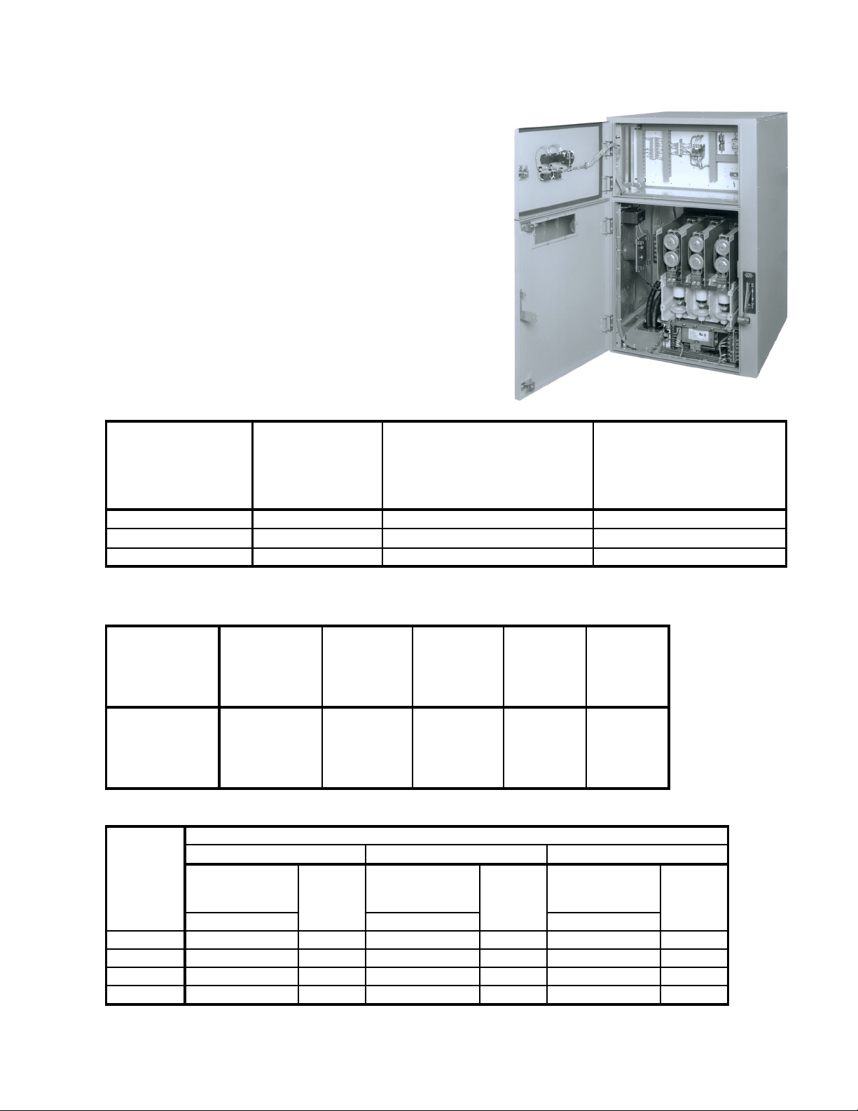
MEDIUM VOLTAGE CONTROLLERS
JK400 Series
The JK400 Series of motor controller is the result
of extensive research and development. This
state-of-the-art controller was designed in
Houston, T exas, and is currently being manufactured under ISO 9001 standards in the same
manufacturing facility as Toshiba motors and
drives. The components in this new series have
been arranged in the most logical manner to
produce a tightly designed unit, and in the full
voltage type starters, uses no internal power
cables. This streamlined, space saving design
provides the ultimate in maintenance ease and
safety features.
These medium voltage controllers are available in
across-the-line or reduced voltage models for the
control of induction, wound rotor or synchronous
motors, transformers, or capacitors up to 6.6kV .
All controllers are designed to meet NEMA Class
E2 requirements. These fixed type controllers
are available in one or two high enclosures with
the following standard features:
Standard Features Full & Reduced
Voltage Controllers
T oshiba Medium V oltage V acuum Cont actor 400A
Bolted Pressure Switch Connections
30" Wide Footprint (Even in a T wo High Design)
Rigid 1 1 Gauge S teel Frame
Front Accessible Main Bus
Current Transformers
Current Limiting, High Interrupting Capacity ,
"R" Rated Motor Starting Fuses
Start and Stop Push Buttons
Run and Off Pilot Lights
Single Phase Ammeter
Control Power Transformer with Primary
and Secondary Fuses
Thermal Bimetallic Overload Relay
S eparate Medium and Low Voltage
Compartments
Built-in Run/T est Circuit
Mechanical and Electrical Interlocks
Isolated Low Voltage Compartment
The low voltage section is oversized and is at a
convenient height. This section is isolated from
the medium voltage section and includes:
Thermal Overload Protection Relay
Pilot Lights (door mounted)
Push Buttons (door mounted)
Single Phase Ammeter (door mounted)
CPT Secondary Fuses
Control T erminal Point s for Customer Connections
Timers (for Reduced V oltage Controllers)
Standard Options:
Metering & Metering Switches
Ground Fault Protection Relay
Phase Sequence Protection Relay
RTD Monitor/Relay
Solid State (2E) Protection Relay
(Overload/Single Phase)
S2E21 Multi-funtion Protection Relay
Visible, Bolted Pressure, Isolation Switch
Standard Features:
Bolted Pressure Isolation Switch
Less Resistance
Less Wear
Zero Insertion Pressure
Mechanical Interlocking System
Reduced Voltage Autotransformer
Controller
Additional Standard Features:
Shorting and Run, 400 Ampere, Vacuum
Contactors
NEMA Medium Duty, Three Winding, Copper
Wound Autotransformer with 50%, 65%, and
80% Taps
Adjustable Solid State Transition Timer
Adjustable Solid State Incomplete Sequence
Timer
If UL or CUL is required, specify when ordering.
Consult Factory for applicable models and options.
Page 3
g
r
MEDIUM VOLTAGE CONTROLLERS
p
JK400 Series
Toshiba's JK400 series complies with EEMAC,
NEMA, UL and CSA standards and is available in
non-reversing and reversing full voltage, autotransformer, reactor, multi-speed, synchronous and
wound rotor configurations. Latched contactors
are also available.
The JK400 series is available in the following
enclosed ratings:
360 amps
2300-6600 Volts
Up to 5,000 HP
Current Rating
Maximum
Continuous
Enclosure Type
Type 1 Ventilated 360 360 320
Type 1 Non-Ventilated 320 320 280
Type 12, 3, 3R 310 310 280
* Actual limits based on your specific application parameters. All specifications subject to change without notice.
Amperes*
46" and 61"
One-Hi
h Controlle
Maximum Continuous Amperes*
90" One-High Controller or Lower
Controller in a Two-High Stacking
Arrangement
Maximum Continuous
Amperes*
Upper Controller in a Two-High
Stacking Arrangement
Short Circuit & Withstand Capability
Interrupting
Capacity
(Symmetrical
Amperes)
50,000
@ 2.3 - 6.6 kV
Interrupting
Capacity
(Symmetrical
MVA)
200 @ 2.3 kV
350 @ 4.0 kV
400 @ 4.6 kV
570 @ 6.6 kV
Short Time
Capability
30 Seconds
(Amperes)
2400 6000 18.2 60
Short Time
Capability
1 Second
(Amperes)
Dielectric
Withstand
1 Minute
(kVAC)
Impulse
Voltage
Withstand
(kV)
Application Table
Enclosed
Maximum
Continuous
Current
(Amperes)
360 1500 1750 1500 2500 3000 2500 4000 5000 4000
320 1250 1500 1250 2250 2500 2250 3500 4500 3500
310 1250 1500 1250 2000 2500 2000 3500 4000 3500
280 1000 1250 1000 1750 2250 1750 3000 3500 3000
For transformer and capacitor load switching applications, consult factory.
2300 Volts, 3 Phase 4200 Volts, 3 Phase 6600 Volts, 3 Phase
Synchronous
Motors
0.8 PF 1.0 PF 0.8 PF 1.0 PF 0.8 PF 1.0 PF
Maximum Horse
Induction
Motors
Synchronous
ower at Utilization Voltage
Motors
Induction
Motors
Synchronous
Motors
Induction
Motors
Page 4

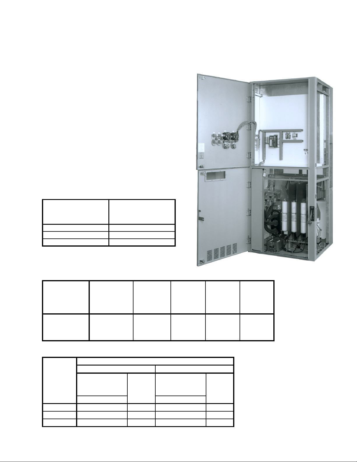
MEDIUM VOLTAGE CONTROLLERS
JK720 Series
The new JK720 Series of motor controller is the
result of extensive research and development.
This state-of-the-art controller was designed in
Houston, T exas, and is currently being manufactured under ISO 9001 standards in the same
manufacturing facility as Toshiba motors and
drives. The components in this new series have
been arranged in the most logical manner to
produce a tightly designed unit. This streamlined, space saving design provides the ultimate
in maintenance ease and safety features.
These medium voltage controllers are available in
across-the-line or reduced voltage models for the
control of induction, wound rotor or synchronous
motors, transformers, or capacitors up to 4.8kV .
All controllers are designed to meet NEMA Class
E2 requirements. These fixed type controllers
are available in one high enclosures with the
following standard features:
Standard Features Full & Reduced
Voltage Controllers
T oshiba Medium V oltage Vacuum Contactor 720A
Bolted Pressure Switch Connections
36" Wide Footprint
Rigid 1 1 Gauge S teel Frame
Front Accessible Main Bus
Current Transformers
Current Limiting, High Interrupting Capacity ,
"R" Rated Motor Starting Fuses
Start and Stop Push Buttons
Run and Off Pilot Lights
Single Phase Ammeter
Control Power Transformer with Primary
and Secondary Fuses
Thermal Bimetallic Overload Relay
Separate Medium and Low Voltage
Compartments
Built-in Run/T est Circuit
Mechanical and Electrical Interlocks
Isolated Low Voltage Compartment
The low voltage section is oversized and is at a
convenient height. This section is isolated from
the medium voltage section and includes:
Thermal Overload Protection Relay
Pilot Lights (door mounted)
Push Buttons (door mounted)
Single Phase Ammeter (door mounted)
CPT Secondary Fuses
Control T erminal Point s for Customer Connections
Timers (for Reduced V oltage Controllers)
Standard Options:
Metering & Metering Switches
Ground Fault Protection Relay
Phase Sequence Protection Relay
RTD Monitor/Relay
Solid State (2E) Protection Relay
(Overload/Single Phase)
S2E21 Multi-funtion Protection Relay
Standard Features:
Bolted Pressure Isolation Switch
Less Resistance
Less Wear
Zero Insertion Pressure
Mechanical Interlocking System
Reduced Voltage Autotransformer
Controller
Additional Standard Features:
Shorting (400A) and Run (720A), V acuum
Contactors
NEMA Medium Duty , Three Winding, Copper
Wound Autotransformer with 50%, 65%, and
80% Taps
Adjustable Solid State Transition Timer
Adjustable Solid State Incomplete Sequence
Timer
If UL or CUL is required, specify when ordering.
Consult Factory for applicable models and options.
Page 5
MEDIUM VOLTAGE CONTROLLERS
A
JK720 Series
Toshiba's JK720 series complies with EEMAC,
NEMA, UL and CSA standards and is available in
non-reversing and reversing full voltage, autotransformer, reactor, multi-speed, synchronous and
wound rotor configurations. Latched contactors
are also available.
The JK720 series is available in the following
enclosed ratings:
720 amps
2300-4800 Volts
Up to 6,000 HP
Note: An Incoming Section is required for the JK720
FVNR, FVR and RVAT type starters, transformer
feeders and capacitor switching controllers.
Current Rating
Maximum Continuous
Enclosure Type
Type 1 Ventilated 720
Type 1 Non-Ventilated 650
Type 12 & 3R 600
Amperes*
One-High Controller
* Actual limits based on your specific application parameters.
All specifications subject to change without notice.
Short Circuit & Withstand Capability
Interrupting
Capacity
(Symmetrical
Amperes)
50,000
@ 2.3 - 4.6 kV
Interrupting
Capacity
(Symmetrical
MVA)
200 @ 2.3 kV
350 @ 4.0 kV
400 @ 4.6 kV
Short Time
Capability
30 Seconds
(Amperes)
4320 10,800
Short Time
Capability
1 Second
(Amperes)
Application Table
Enclosed
Maximum
Continuous
Current
(Amperes)
720 3000 3500 3000 5500 6000 5500
650 2750 3000 2750 5000 5500 5000
600 2500 2750 2500 4500 5000 4500
For transformer and capacitor load switching applications, consult factory.
0.8 PF 1.0 PF 0.8 PF 1.0 PF
Maximum Horsepower at Utilization Voltage
2300 Volts, 3 Phase 4200 Volts, 3 Phase
Synchronous
Motors
Induction
Motors
Synchronous
Motors
Dielectric
Withstand
1 Minute
(kV)
C 13.25
DC 19
Induction
Motors
Impulse
Voltage
Withstand
(kV)
60
Page 6

1. Standards
1.1 Basic controller shall comply with NEMA ICS3-1993, Part 2 (ICS2-324) and UL 347
Standards. Basic controller can be UL Listed and CSA Certified.
2. Structure
2.1 Dimensions
FVNR One-high - 30"W x 36"D x 46"H (no bus, small LV compartment)
FVNR One-high - 30"W x 36"D x 61"H (bus provision, large LV compartment)
FVNR One-high - 30"W x 36"D x 90"H (bus provision, empty upper MV compartment)
FVNR Two-high - 30"W x 36"D x 90"H
RVAT (up to 1250HP) - 36"W x 36"D x 90"H
RVAT (1250HP-4000HP) - 42"W x 36"D x 90"H
2.2 Fabrication
2.2.1 11 gauge frame with 16 gauge side, back and top sheets.
2.2.2 Front of cubicle to be an all-welded assembly. Remainder of frame to be bolted
construction.
JK Series Product Specification
400A MEDIUM VOLTAGE FIXED CONTROLLER
2.2.3 Back and top sheets to be removable for easy access for assembly and wiring.
2.2.4 Basic dimensions and squareness of cubicle to be controlled by accurately located NCpunches holes. With exception of welded front frame, cubicle should be capable of being
assembled without a fixture.
2.2.5 All doors shall be minimum 12 gauge steel.
2.2.6 All structural components shall be given a corrosion resistant finish by either galvanizing or
painting. Galvanized steel shall be used only for internal structural members or panels.
2.2.7 All panels used to mount low voltage devices shall be painted white for superior visibility.
Panels shall be easily removable or swing-out to provide access to horizontal bus mounted in the
middle rear of the cubicle.
2.3 General Arrangement of Components
2.3.1 Medium voltage compartments, low voltage compartments and power bus compartments
shall be isolated by grounded steel barriers.
2.3.2 Complete front accessibility to all components shall be provided for installation against
walls or for back-to-back arrangements.
2.3.3 Low voltage components shall be located so that components are accessible with medium
voltage doors closed. Low voltage compartment shall be sized with consideration to mounting
commonly used devices.
Page 7

2.4 Handling and Installation
2.4.1 Removable angles or eye bolts shall be provided at the top of the structure for lifting.
3. Power Bus
3.1 Horizontal power bus shall be located at the center rear of the cubicle, in the same location as
other JK Series controllers.
3.2 Horizontal power bus ratings of 1200 and 2000 amperes are available. Bus sizes shall match
those provided in other JK Series controllers.
3.3 Horizontal power bus shall be braced for 50kA RMS symmetrical.
3.4 Horizontal power bus shall be tin plated as standard with insulated bus and silver plating optional.
3.5 Bare copper 1/4 x 2 inch horizontal ground bus shall be available and the location shall match
other JK Series controllers.
3.6 Vertical power bus feeding 400 ampere controllers shall be 1/4 x 1-1/4 inch tin plated copper.
Insulated bus and silver plating are optional.
3.7 Horizontal power bus shall be front accessible by removing or swinging open a panel.
4. Medium Voltage Controllers - 400 Amperes
4.1 Medium Voltage Controller Compartment
4.1.1 The medium voltage controller compartment for controllers rated 400 amperes shall consist
of an isolation switch (4.2), a fixed mounted vacuum contactor (4.3), three fixed mounted power
fuses (4.4), three current transformers and a control power transformer with primary fuses.
Optionally a second control or potential transformer with primary fuses may be provided.
4.1.2 Internal power connections between power components shall be made using either high
voltage cable or bus bars.
4.1.3 Connection of customer's outgoing load cables shall be made to terminals mounted on the
rear of the medium voltage contactor. It shall be possible to terminate outgoing load cables with
the removal of the horizontally mounted power fuses. Sufficient wire bending space shall be
provided for terminating shielded cables as large as 1-2/0 per phase, or unshielded cables as
large as 1-350MCM per phase, top or bottom entry.
4.1.4 A zero sequence current transformer for ground fault sensing when required shall be
provided. It shall be located within the MV compartment where customer’s load cable can be
conveniently passed through the current transformer window prior to termination.
4.1.5 Three current transformers for metering and relaying shall be provided. These shall be of
the window type (or bar type as option) with burden capacity as required for operating the various
meters and relays.
4.1.6 Control power and optional potential transformers shall be of the encapsulated type with
primary fuses. Primary side of transformers shall be wired to the load side of the main controller
power fuses. Transformers shall be arranged to provide easy access for replacement of primary
fuses.
Page 8

4.2 Bolted Pressure Isolation Switch
4.2.1 A Toshiba type JK fixed mounted, gang-operated isolation switch shall be provided with
each controller to isolate the medium voltage compartment from the power source.
4.2.2 The switch shall be directly driven by an externally operable handle mounted on the right
hand flange of the cubicle. The handle shall provide positive indication of the position of the
switch.
4.2.3 The switch mechanism shall be designed such that in the closed position it provides the
equivalent of a bolted pressure joint at both ends of the movable blades, rather than relying on
spring pressure.
4.2.4 The line side of the switch shall be bus connected to the main horizontal power bus or to
the incoming terminals of the controller. The load side of the switch shall be bus connected to
the main controller power fuses.
4.2.5 The switch blades shall automatically ground the line side of the power fuses when the
switch is opened. This allows any stored energy in the controller load circuit to be discharged by
closing the contactor using test power.
4.2.6 It shall be possible to visually confirm that the switch blades are open and grounded by
viewing the blades through the viewing window with the medium voltage door closed. Also, there
shall be a mechanical operated flag (visible through the window in the medium voltage door)
displaying the switch in the “OPEN” position with the door closed.
4.2.7 A shutter mechanism shall automatically isolate the medium voltage compartment from all
live parts when the switch is opened.
4.2.8 The external operating handle for the isolation switch shall be designed to accept up to
three external padlocks in the OFF position.
4.2.9 The switch shall be capable of interrupting the no-load current of the largest control power
transformer which can be connected to it. The interrupting capability of the switch shall be a
minimum of 0.4 amperes at 110% of rated line voltage.
4.2.10 The switch shall be rated as follows:
400 amperes @ 7.2kV
4.2.11 The mechanical life of the switch and its operating mechanism shall be 10,000 operations
minimum.
4.2.12 All switch current-carrying parts shall be silver plated. An optional tin-over-silver plated
switch shall be available for use in paper mill applications.
4.3 Vacuum Contactor
4.3.1 The Toshiba HCV-5HA vacuum contactor shall be used in these controllers.
4.3.2 The contactor shall be bolted into the medium voltage compartment. It shall be arranged
such that the power connections are front-accessible so it can be unbolted and removed if
necessary for maintenance.
Page 9

4.3.3 Power connections from the isolation switch to the main power fuses shall be made using
bus bar. Connections from the contactor through the current transformers to the outgoing load
terminals shall be made using power cable furnished by others.
4.3.4 The contactor shall be available with an optional mechanical latch with provisions for
manual or electrical trip.
4.3.5 The contactor shall be mechanically and electrically interlocked with the isolation switch as
described in the section on interlocking (4.5).
4.4 Power Fuses
4.4.1 The power fuses shall be arranged horizontally at the top of the contactor unit. In this
position, the blown fuse indicators on the fuses shall be visible, through the viewing window, when
the medium voltage door is closed.
4.4.2 The fuse unit shall include either single or double barrel power fuses, R-rated or E-rated, 3"
diameter.
4.5 Interlocking
4.5.1 A mechanical interlock shall be provided between the vacuum contactor and the isolation
switch. The interlock shall prevent the isolation switch from being opened or closed unless the
main contacts of the contactor are opened.
4.5.2 The interlock described in 4.5.1 shall also operate in a manner such that it will prevent the
closing of the main contacts of the vacuum contactor unless the isolation switch is either fully
opened or fully closed.
4.5.3 An electrical interlock shall be provided as a backup to the mechanical interlock in 4.5.1.
This interlock shall switch off control power to the vacuum contactor at any isolating switch
position other than fully opened or fully closed.
4.5.4 A mechanical interlock shall be provided between the isolation switch and the medium
voltage compartment door. This interlock shall prevent the door from being opened unless the
isolating switch is in the fully open position.
4.5.5 The interlock described in 4.5.4 shall be capable of being circumvented in the event
emergency entrance to the controller is required. Circumventing the interlock shall require two
separate and distinct operations and shall require the use of a tool.
4.5.6 A mechanical interlock between the isolation switch and the medium voltage door shall be
provided to prevent the isolating switch from being closed when the door is open. This interlock
shall be capable of being circumvented only by the use of a tool.
4.5.7 An electrical interlock shall be provided to ensure the isolation switch does not open with
the control power transformer under load. This interlock shall be designed such that during
switch opening, the transformer secondary is disconnected prior to the opening of the switch
blades. Also, the isolating switch blades must close before the secondary load is reconnected.
4.5.8 An electrical interlock shall be provided to prevent the vacuum contactor from being closed
using external test power unless the isolation switch is fully opened and the secondary of the
normal control power transformer is disconnected from the control circuit to prevent backfeeding
the transformer.
Page 10

5. Ratings
5.1 Controller shall be rated as follows:
5.1.1 Interrupting Ratings:
400 Ampere Controller:
- contactor 7.0kA @ 6.9kV
- fused controller 50kA RMS Sym. @ 7.2kV
5.1.2 Continuous Thermal Ratings:
400 Ampere Controller:
200MVA @ 2.3kV
350MVA @ 4.0kV
400MVA @ 4.6kV
570MVA @ 6.6kV
Enclosure type Max. Continuous
Amperes
46” and 61” One-high
controller
Max. Continuous
Amperes
90” One-high controller or
Lower controller in a Two-
high stacking
Max. Continuous
Amperes
Upper controller in a
Two-high stacking
arrangement
arrangement
NEMA-1 Ventilated 360 360 320
NEMA-1 Non-ventilated 320 320 280
NEMA-12/3R 310 310 280
5.1.3 Short Time Thermal Rating:
400 Ampere Contactor: 2400A for 30 seconds
6000A for 1 second
5.1.4 Impulse Withstand:
400 Ampere Controller: 60kV
1.2 x 50 microsecond wave
Rev. 2, 2/16/1999
Page 11

1. Standards
1.1 Basic controller shall comply with NEMA ICS3-1993, Part 2 (ICS2-324) and UL 347
Standards. Basic controller can be UL/CUL Listed.
2. Structure
2.1 Dimensions
Across-the-Line (one-high) - 36"W x 36"D x 90"H
Reduced Voltage Autotransformer - (2) 36"W x 36"D x 90"H
2.2 Fabrication
2.2.1 11 gauge frame with 16 gauge side, back and top sheets.
2.2.2 Front of cubicle to be an all-welded assembly. Remainder of frame to be bolted
construction.
2.2.3 Side, back and top sheets to be removable for easy access for assembly and wiring.
2.2.4 Basic dimensions and squareness of cubicle to be controlled by accurately located NCpunches holes. With exception of welded front frame, cubicle should be capable of being
assembled without a fixture.
JK Series Product Specification
720A MEDIUM VOLTAGE FIXED CONTROLLER
2.2.5 All doors shall be minimum 12 gauge steel.
2.2.6 All structural components shall be given a corrosion resistant finish by either galvanizing or
painting. Galvanized steel shall be used only for internal structural members or panels.
2.2.7 All panels used to mount low voltage devices shall be painted white for superior visibility.
Panels shall be easily removable or swing-out to provide access to horizontal bus mounted in the
rear of the cubicle.
2.3 General Arrangement of Components
2.3.1 Medium voltage compartments, low voltage compartments, power bus compartments and
field conductor wireways shall be isolated by grounded steel barriers.
2.3.2 Complete front accessibility to all components shall be provided for installation against
walls or for back-to-back arrangements.
2.3.3 Low voltage components shall be located so that components are accessible with medium
voltage door closed. Low voltage compartment shall be sized with consideration to mounting
commonly used devices.
2.4 Handling and Installation
Page 12

2.4.1 Removable angles or eye bolts shall be provided at the top of the structure for lifting.
2.4.2 Optional removable sill channels shall be available.
3. Power Bus
3.1 Horizontal power bus shall be located at the center rear of the cubicle, in the same location as
other JK Series controllers.
3.2 Horizontal power bus ratings of 1200 and 2000 amperes shall be available. Bus sizes shall
match those provided in other JK Series controllers.
3.3 Horizontal power bus shall be braced for 50kA RMS symmetrical.
3.4 Horizontal power bus shall be tin plated as standard with silver plating optional.
3.5 Bare copper 1/4 x 2 inch horizontal ground bus shall be available and the location shall match
other JK Series controllers.
3.6 Vertical power bus feeding 720 ampere controllers shall be 3/8 x 2 inch tin plated copper. Silver
plating shall be optional.
3.7 Horizontal power bus shall be front accessible by removing or swinging open a panel.
4. Medium Voltage Controllers - 720 Amperes
4.1 Medium Voltage Controller Compartment
4.1.1 The medium voltage controller compartment for controllers rated 720 amperes shall consist
of an isolation switch (4.2), a fixed mounted vacuum contactor (4.3), three fixed mounted power
fuses (4.4), three current transformers and a control power transformer with primary fuses.
Optionally a second control or potential transformer with primary fuses may be provided.
4.1.2 Internal power connections between power components shall be made using either high
voltage cable or bus bars.
4.1.3 Connection of customer's outgoing load cables shall be made to terminals mounted on the
left side of the medium voltage compartment. It shall be possible to terminate outgoing load
cables without the removal of major components such as the vacuum contactor and power fuses.
Sufficient wire bending space shall be provided for terminating shielded cables as large as 2500MCM per phase, top or bottom entry.
4.1.4 A zero sequence current transformer for ground fault sensing when required shall be
provided. It shall be located such that factory installed internal power cables from all three
phases shall pass through its window. Ground current sensors for Toshiba 2E ground fault
module and Multilin ground fault relay shall be available as a minimum.
4.1.5 Three current transformers for metering and relaying shall be provided. These shall be of
the window type with burden capacity as required for operating the various meters and relays.
4.1.6 Control power and optional potential transformers shall be of the encapsulated type with
integral primary fuses. All transformers shall be rated 60kV BIL. Primary side of transformers
shall be wired to the load side of the main controller power fuses. Transformers shall be
arranged to provide easy access for replacement of primary fuses.
Page 13

4.2 Bolted Pressure Isolation Switch
4.2.1 A fixed mounted, gang-operated isolation switch shall be provided with each controller to
isolate the medium voltage compartment from the power source.
4.2.2 The switch shall be directly driven by an externally operable handle mounted on the right
hand flange of the cubicle. The handle shall provide positive indication of the position of the
switch.
4.2.3 The switch mechanism shall be designed such that in the closed position it provides the
equivalent of a bolted pressure joint at both ends of the movable blades, rather than relying on
spring pressure.
4.2.4 The line side of the switch shall be bus connected to the main horizontal power bus or to
the incoming terminals of the controller. The load side of the switch shall be bus connected to
the main controller power fuses.
4.2.5 The switch blades shall automatically ground the line side of the power fuses when the
switch is opened. This allows any stored energy in the controller load circuit to be discharged by
closing the contactor using test power.
4.2.6 It shall be possible to visually confirm that the switch blades are open and grounded by
viewing the blades through the viewing window with the medium voltage door closed. Also, there
shall be a mechanical operated flag (visible through the window in the medium voltage door)
displaying the switch in the “OPEN” position with the door closed.
4.2.7 A shutter mechanism shall automatically isolate the medium voltage compartment from all
live parts when the switch is opened.
4.2.8 The external operating handle for the isolation switch shall be designed to accept up to
three external padlocks in the OFF position.
4.2.9 The switch shall be capable of interrupting the no-load current of the largest control power
transformer which can be connected to it. The interrupting capability of the switch shall be a
minimum of 0.4 amperes at 110% of rated line voltage.
4.2.10 The switch shall be rated as follows:
720 amperes @ 5.0kV
4.2.11 The mechanical life of the switch and its operating mechanism shall be 10,000 operations
minimum.
4.2.12 All switch current-carrying parts shall be silver plated. An optional tin-over-silver plated
switch shall be available for use in paper mill applications.
4.3 Vacuum Contactor
4.3.1 The Toshiba CV-6KAU vacuum contactor shall be used in these controllers.
4.3.2 The contactor shall be bolted into the medium voltage compartment. It shall be arranged
such that the power connections are front-accessible so it can be unbolted and removed if
necessary for maintenance.
Page 14

4.3.3 Power connections from the isolation switch to the contactor shall be made using bus bar.
Connections from the contactor through the current transformers to the outgoing load terminals
shall be made using power cable.
4.3.4 The contactor shall be supplied with an optional mechanical latch with provisions for
manual or electrical trip.
4.3.5 The contactor shall be fully mechanically and electrically interlocked with the isolation
switch as described in the section on interlocking (4.5).
4.4 Power Fuses
4.4.1 Main current-limiting power fuses shall be provided for both motor starting (R rated) and
transformer feeder (E rated) applications.
4.4.2 Available fuse ratings for motor starting applications shall be Gould Type A051B2DAR0
rated 38R (630A), 5kV or A051B3DAR0 rated 57X (900A), 5kV.
4.4.3 Available fuse ratings for transformer feeder applications shall be Gould Type
A055C2D0R0-500E and 600E, and A055B3D0R0-750E and 900E, rated 5.5kV.
4.4.4 All power fuses shall employ bolt-in mounting.
4.4.5 The blown fuse indicators on the fuses shall be visible, through the viewing window, when
the medium voltage door is closed.
4.5 Interlocking
4.5.1 A mechanical interlock shall be provided between the vacuum contactor and the isolation
switch. The interlock shall prevent the isolation switch from being opened or closed unless the
main contacts of the contactor are opened.
4.5.2 The interlock described in 4.5.1 shall also operate in a manner such that it will prevent the
closing of the main contacts of the vacuum contactor unless the isolation switch is either fully
opened or fully closed.
4.5.3 An electrical interlock shall be provided as a backup to the mechanical interlock in 4.5.1.
This interlock shall switch off control power to the vacuum contactor at any switch position other
than fully opened or fully closed.
4.5.4 A mechanical interlock shall be provided between the isolation switch and the medium
voltage compartment door. This interlock shall prevent the door from being opened unless the
switch is in the fully open position.
4.5.5 The interlock described in 4.5.4 shall be capable of being circumvented in the event
emergency entrance to the controller is required. Circumventing the interlock shall require two
separate and distinct operations and shall require the use of a tool.
4.5.6 A mechanical interlock between the isolation switch and the medium voltage door shall be
provided to prevent the switch from being closed when the door is open. This interlock shall be
capable of being circumvented only by the use of a tool.
Page 15

4.5.7 An electrical interlock shall be provided to ensure the isolation switch does not open with
the control power transformer under load. This interlock shall be designed such that during
switch opening, the transformer secondary is disconnected prior to the opening of the switch
blades. Also, during switch closing, the switch blades must close before the secondary load is
reconnected.
4.5.8 An electrical interlock shall be provided to prevent the vacuum contactor from being closed
using external test power unless the isolation switch is fully opened and the secondary of the
normal control power transformer is disconnected from the control circuit to prevent backfeeding
the transformer.
5. Ratings
5.1 Controllers shall be rated as follows:
5.1.1 Interrupting Ratings
- Contactor 7.2kA @ 6.6kV Max.
- Controller 50kA RMS Sym. @ 5.0kV Max.
5.1.2 Continuous Current Ratings
N-1 Enclosure (Ventilated) 720A
N-1 Enclosure (Non-ventilated) 650A
N-12, 3, 3R Enclosure 600A
200MVA @ 2.3kV
350MVA @ 4.0kV
400MVA @ 4.6kV
5.1.3 Horsepower Ratings - Induction Motors (Approximate)
5.1.4 Short Time Current Ratings
5.1.5 Impulse Voltage Withstand
Rev. 5, 2/16/1999
@2.3kV@4.2kV
N-1 Enclosure (Ventilated) 3000 5500
N-1 Encl. (Non-ventilated) 2750 5000
N-12, 3, 3R Enclosure 2500 4500
4320A - 30 seconds
10,800A - 1 second
60kV
1.2 x 50 microsecond wave
Page 16

Page 17

Page 18

Page 19

Page 20

Page 21

Page 22

Page 23

North America Headquarters & Manufacturing Facilities (Houston, TX)
TOSHIBA - Quality by Design
Our company culture and history is strongly rooted in quality. Our designs are
technologically innovative and our products are manufactured from start to end
using only the highest quality foreign and domestic parts.
Product Warranty
Toshiba offers a comprehensive warranty program on its full line of industrial
products. Consult your salesperson or the factory for specific information.
Medium Voltage Motor
G7 Drive
Need to Know More?
Be sure to visit our website located at www.tic.toshiba.com for the latest
information on Toshiba products.
Customer Support Services
Toshiba offers 24 hour service nationwide. For assistance of any type,
call: 1-800-231-1412
ADJUSTABLE SPEED DRIVES MOTORS CONTROLS UPS INSTRUMENTATION PLC
Available Through:
INDUSTRIAL DIVISION
13131 West Little York Road, Houston, Texas 77041
Tel 713/466-0277 Fax 713/466-8773
US 800/231-1412 Canada 800/872-2192 Mexico 01/800/527-1204
www.tic.toshiba.com
Copyright 2/2005
*pacjKSBROCH050218*
 Loading...