

Page 1
POWER DISTRIBUTION
Solid
State Starters
Medium Voltage
200-400-600-720A
JK Series
Page 2

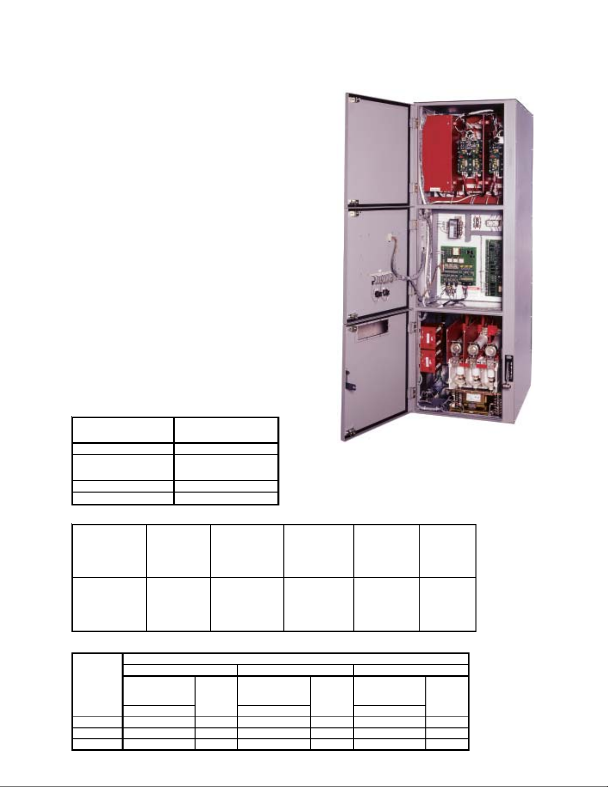
SOLID STATE STARTER
JKSSS4+ Series
The JKSSS Series of motor starter is the result of
extensive research and development. This
streamlined, space saving design (only 30" wide)
provides the ultimate in maintenance ease and
safety features. These medium voltage solid state
starters are available for the control of induction,
wound rotor or synchronous motors, up to 6.9kV.
All starters are designed to meet NEMA Class E2
requirements.
Features
Soft Start
125% Continuous Duty
500% - 60 Seconds, 600% - 30 Seconnds
30" Wide Footprint
Digital Microprocessor Control
LCD Display w/Programming Keypad
Toshiba Medium Voltage Vacuum Contactors,
for Bypass and Input Isolation
Incoming, 400A JK Disconnect Switch - Bolted
Pressure Switch Connections
Current Limiting, High Interrupting Capacity,
"R" Rated Motor Starting Fuses
Two Stage Solid State Motor Protection
Starting: Programmable for Class 5 through 30
Running: Programmable for Class 5 through 30
Control Power Transformers with Primary and
Secondary Fuses
NEMA Type 1 Enclosure
Separate Medium and Low Voltage Compartments
Mechanical and Electrical Interlocks
Visible, Bolted Pressure, Isolation Switch
Less Resistance
Less Wear
Zero Insertion Pressure
Mechanical Interlocking System
Isolated Low Voltage Compartment
The low voltage section is oversized and is at a
convenient height. This section is isolated from
the medium voltage section.
Digital Control Module
LCD Display (two lines) and Status LEDs
(Power, Run, Alarm, Aux. Relays)
Programming Keypad (Non-volatile Memory)
Maintenance Data
Fault indications: Shorted SCR, Phase Loss, Shunt
Trip, Phase Imbalance, Phase Rotation, Overload,
Overtemp, Overcurrent, Short Circuit, Load Loss,
Ground Fault, Stator Phase Trip, RTD Trip, or Any Trip
Coast Down Time
Starts per Hour
Time Between Starts
Event History - Up to 60 events. Data includes
cause, date, time, phase and ground current.
Additional Features
Serial Communication Port:
RS485 or RS422 with Modbus RTU Protocol or
RS485 or RS422 with Windows Interface
Rugged Gate Firing Circuit Using Ring Transformer
Opto-isolated Inputs
Auxiliary Contacts - Form C, 5A @ 240Vac max.
Adjustments
Motor Full Load Ampere (FLA)
Dual Adjustments - Two independent settings
Initial Voltage 0 - 100% of nominal voltage
Current Limit 200 - 500% of motor FLA
Acceleration Time 1 - 120 seconds
Deceleration Time 1 - 60 seconds
Three custom Accel curves
Jog: 5 - 100% Volt., 1 - 20 sec., Current 100 - 500%
Kick Start: 10 - 100% Voltage, 0.1 - 2 sec.
Coast Down (Back Spin) Lockout Timer 1 - 60 min.
Starts-per-Hour Lockout Timer
1 - 10 successful starts per hour
1 - 60 min. between start attempts
Undercurrent 10 - 90% (with adjustable trip delay
1 - 60 sec.)
Overload Reset - Selectable Manual or Automatic
Two 4 - 20 mA Analog Outputs: Selectable from
Off, RPM, Hottest Non-Stator RTD, Hottest Stator
RTD, RMS Current, % of Motor Load
Options
Drawout Input Isolation, Vacuum Contactor
NEMA Type 12 or 3R Enclosure
1200 or 2000A Main Copper Bus
Available in MCC Lineups with Other JK Series
Starters (FVNR, FVR, RVAT, Synchronous, Etc.)
Available in MCC Lineups with Main Incoming
Disconnect Switch or Toshiba Vacuum
Circuit Breaker
The soft start is available as a controller only for
users which already have an existing full voltage
starter (disconnect switch, main power fuses &
contactor) and wants to add reduced voltage
starting and soft stop features.
PFC Contactor - Vacuum contactor for switching
Power Factor Correction Capacitor.
Manual (Full Voltage) Bypass Selection with solid
state protection (2E) or bimetallic overload.
If UL or CUL is required, specify when ordering.
Consult Factory for applicable models and options.
Page 3
SOLID STATE STARTER
JKSSS4+ Series
T oshiba's JKSSS4 series complies with EEMAC,
NEMA, UL and CSA standards and is available in
non-reversing and reversing, multi-speed, synchronous and wound rotor configurations.
The JKSSS4 series is available in the following
enclosed ratings:
360 Amps Max.
2300-6900 Volts
Protective Features
z Electronic Overload:
Retentive Thermal Memory
Dynamic Reset Memory
z Phase Imbalance/Single Phase
z Short Circuit
z Ground Fault - Optional
z RTD T emperature
z Phase Reversal/Phase Sequence
z Overcurrent
z Start s-per-Hour
z Shorted SCR
z Undercurrent/Loss of Load
z Starter Overtemperature
z Shorted SCR
z Undervoltage
z Overvoltage
Continuous Current
Enclosure T ype
Type 1 Ventilated 360A
Type 12 Ventilated w/
Fans & Type 12 Filters
Type 1 Non-Ventilated 300A
Type 12 & 3R 300A
Short Circuit & Withstand Capability
Max. Continuous Amps*
90" One-High Controller
310A
Interrupting
Capacity
(Symmetrical
Amperes)
Interrupting
Capacity
(Symmetrical
MVA)
Short Time
Capability
30 Seconds
(Amperes)
Short Time
Capability
1 Second
(Amperes)
Dielectric
Withstand
1 Min ute
(kVAC)
200 @ 2.3 kV
50,000
@ 2.3 - 6. 6 kV
350 @ 4.0 kV
400 @ 4.6 kV
2400 6000 18.2 60
570 @ 6.6 kV
Approximate Maximum Horsepower Based on Continuous Current
Enclosed
Maximum
Continuous
Current
(Amperes)
360 1500 1750 1500 2500 3000 3000 4000 5000 4500
320 1250 1500 1250 2250 2500 2500 3500 4000 4000
300 1000 1250 1000 2000 2500 2250 3000 3500 3500
Synchronous
0.8 PF 1.0 PF 0.8 PF 1.0 PF 0.8 PF 1.0 PF
2300V 4200V 6600V
Motors
Maximum Horsepower at Utilization Voltage
Induction
Motors
Synchronous
Motors
Induction
Motors
Synchronous
Motors
Impulse
Voltage
Withstand
(kV)
Induction
Motors
If UL or CUL is required,
specify when ordering.
Consult Factory for
applicable models and
options.
Page 4

SOLID STATE STARTER
JKSSS7+ Series
The new JKSSS7+ Series of motor starter is the
result of extensive research and development.
These medium voltage solid state starters are
available for the control of induction, wound rotor
or synchronous motors up to 4.8kV. All controllers are designed to meet NEMA Class E2
requirements.
Features
Soft Start
125% Continuous Duty
500% - 60 Seconds, 600% - 30 Seconds
Digital Microprocessor Control
LCD Display w/Programming Keypad
Toshiba Medium Voltage Vacuum Contactors,
for Bypass and Input Isolation
Incoming, 720A JK Disconnect Switch - Bolted
Pressure Switch Connections
Current Limiting, High Interrupting Capacity,
"R" Rated Motor Starting Fuses
Two Stage Solid State Motor Protection -
Starting: Programmable for Class 5 through 30
Running: Programmable for Class 5 through 30
Control Power Transformers with Primary and
Secondary Fuses
NEMA Type 1 Enclosure
Separate Medium and Low Voltage Compartments
Mechanical and Electrical Interlocks
Visible, Bolted Pressure, Isolation Switch
Less Resistance
Less Wear
Zero Insertion Pressure
Mechanical Interlocking System
Isolated Low Voltage Compartment
The low voltage section is oversized and is at a
convenient height. This section is isolated from
the medium voltage section.
Digital Control Module
LCD Display (two lines) and Status LEDs
(Power, Run, Alarm, Aux. Relays)
Programming Keypad (Non-volatile Memory)
Maintenance Data
Fault indications: Shorted SCR, Phase Loss, Shunt
Trip, Phase Imbalance, Phase Rotation, Overload,
Overtemp, Overcurrent, Short Circuit, Load Loss,
Ground Fault, Tach Accel Trip, Stator Phase Trip,
RTD Trip, or Any Trip
Coast Down Time
Starts per Hour
Time Between Starts
Any Lockout
Event History - Up to 60 events. Data includes
cause, date, time, phase and ground current.
Adjustments
Motor Full Load Ampere (FLA)
Dual Adjustments - Two independent settings
Initial Voltage 0 - 100% of nominal voltage
Current Limit 200 - 500% of motor FLA
Acceleration Time 1 - 120 seconds
Deceleration Time 1 - 60 seconds
Three custom Accel curves
Jog: 5 - 100% Volt., 1 - 20 sec., Current 100 - 500%
Kick Start: 10 - 100% Voltage, 0.1 - 2 sec.
Coast Down (Back Spin) Lockout Timer 1 - 60 min.
Starts-per-Hour Lockout Timer
1 - 10 successful starts per hour
1 - 60 min. between start attempts
Undercurrent 10 - 90% (w/1 - 60 sec trip delay)
Overload Reset - Selectable Manual or Automatic
Two 4 - 20 mA Analog Outputs: Selectable from
Off, RPM, Hottest Non-Stator RTD, Hottest Stator
RTD, RMS Current, % of Motor Load
Options
NEMA Type 12 or 3R Enclosure
1200 or 2000A Main Copper Bus
Available in MCC Lineups with Other JK Series
Starters (FVNR, FVR, RVAT, Synchronous, Etc.)
Available in MCC Lineups with Main Incoming
Disconnect Switch or Vacuum Circuit Breaker
The soft start is available as a controller only for
users which already have an existing full voltage
starter (disconnect switch, main power fuses &
contactor) and wants reduced voltage starting
and soft stop features.
PFC Contactor - Vacuum contactor for switching
Power Factor Correction Capacitor.
Manual (Full Voltage) Bypass Selection with solid
state protection (2E) or bimetallic overload.
Page 5

SOLID STATE STARTER
AC 13.25
Continuous
Induction
JKSSS7+ Series
T oshiba's JKSSS7 series complies with EEMAC,
NEMA, UL and CSA standards and is available for
induction, synchronous and wound rotor configurations.
The JKSSS7 series is available in the following enclosed ratings:
600 & 720 Amp s, 2300-4800 Volts, Up to 6,000 HP
Protective Features
Electronic Overload:
Retentive Thermal Memory w/Dynamic Reset Memory
Phase Imbalance/Single Phase
Short Circuit
Ground Fault - Optional
RTD T emperature
Phase Reversal/Phase Sequence
Overcurrent
Start s-per-Hour
Shorted SCR
Undercurrent/Loss of Load
Starter Overtemperature
Shorted SCR
Undervoltage
Overvoltage
Microprocessor Digital Control Unit (DCU) **
Programming Keypad:
Operator Control
System/Motor Protection
Serial Communication (RS485)
Statistical Data
LCD status and alarm display with Twelve LEDs
POWER - Indicates control power is present
RUN - Indicates unit/motor is running
ALARM - Lights in conjunction with AUX 2 to
indicate event or warn of possible critical condition
TRIP - Lights in conjunction with AUX 1 to
indicate a critical condition has occurred.
AUX 1-8 - Auxiliary unit relays
** Standard on all JKSSS4+ & JKSSS7+ models, 200-720A, 2300-6900V
Additional Features
Serial Communication Port:
RS485 or RS422 with Modbus RTU Protocol or
RS485 or RS422 with Windows Interface
Rugged Gate Firing Circuit Using Ring Transformer
Opto-isolated Inputs
Continuous Current
Maximum Continuous
Enclosure Type
Amperes*
One-High Controller
Type 1 Ventilated 720
Type 1 Non-Ventilated 650
Type 12 & 3R 600
Short Circuit & Withstand Capability
Interrupting
Capacity
(Symmetrical
Amperes)
50,000
@ 2.3 - 4.6 kV
Interrupting
Capacity
(Symmetrical
MVA)
200 @ 2.3 kV
350 @ 4.0 kV
400 @ 4.6 kV
Short Time
Capability
30 Seconds
(Amperes)
4320 10,800
Short Time
(Amperes)
Capability
1 Second
Dielectric
Withstand
1 Minute
(kV)
DC 19
Impulse
Voltage
Withstand
(kV)
60
Approximate Maximum Horsepower Based on Continuous Current
Enclosed
Maximum
Current
(Amperes)
720 3000 3500 3000 5500 6000 5500
650 2750 3000 2750 5000 5500 5000
600 2500 2750 2500 4500 5000 4500
Maximum Horsepower at Utilization Volt age
2300 Volts, 3 Phase 4200 Volts, 3 Phase
Synchronous
Motors
0.8 PF 1.0 PF 0.8 PF 1.0 PF
Induction
Motors
Synchronous
Motors
Motors
Metering **
Percent of FLA
Phase Current (A, B & C)
Average Current
Ground Fault Current (w/Optional GF
Protection)
Remaining Thermal Register
Thermal Capacity to Start
Average Start Time
Average St art Current
Measured Capacity to Start
Time Since Last Start
Line Frequency
Phase Order
Motor RPM
kW, kV A, kV AR, PF , MWHr
kW Demand, kVA Demand, kVAR
Demand, Amps Demand - (All Date/
Time Stamped)
** Standard on all JKSSS4+ & JKSSS7+
models, 200-720A, 2300-6900V
Page 6

Typical Dimensions and Mechanical Layout for 2300-4200V, 360A Max. Starter
Dimensions are for reference only.
Page 7

T ypical Dimensions and Mechanical Layout for 2300-4200V, 600A & 720A St arter
Dimensions are for reference only.
Page 8

*pacjKSss050218*
ADJUSTABLE SPEED DRIVES
MOTORS
CONTROLS UPS INSTRUMENTATION
PLC
INDUSTRIAL DIVISION
Tel 713/466-0277 Fax 713/466-8773
US 800/231-1412 Canada 800/872-2192 Mexico 01/800/527-1204
www.tic.toshiba.com
Copyright 2/2005
Available Through:
TOSHIBA - Quality by Design
Our company culture and history is strongly rooted on quality. Our designs
are technologically innovative and our products are manufactured from start to
end using only the highest quality foreign & domestic parts.
Toshiba offers a comprehensive warranty program on its full line of industrial
North America Headquarters & Manufacturing Facilities (Houston, TX)
Medium Voltage Motor
G7 Drive
 Loading...