

Air to Air Heat Exchanger
AMP Air Conditioning
www.ampair.co.uk | sales@ampair.co.uk
Installation Manual
Concealed microcomputer
control type
Model name:
VN-M150HE
VN-M250HE
VN-M350HE
VN-M500HE
VN-M650HE
VN-M800HE
VN-M1000HE
For commercial use
Installation Manual 1
Installation Manual xx
English
Xxxxx
1-EN 2-EN
AMP Air Conditioning
www.ampair.co.uk | sales@ampair.co.uk
Air to Air Heat Exchanger
Installation Manual
–1–
Air to Air Heat Exchanger
Installation Manual
Original instruction
Thank you very much for purchasing TOSHIBA Air to Air Heat Exchanger.
Please read this owner’s manual carefully before using your Air to Air Heat Exchanger.
• Obtain the “Owner’s manual” and “Installation manual” from constructor (or dealer).
Request to constructor or dealer
• Please clearly explain the contents of the Owner’s manual and hand over it.
• Read this Installation Manual thoroughly to fully understand everything about your Toshiba Air to Air Heat
Exchanger and be able to install it properly.
• Ask a qualified installer or qualified service person to perform installation.
• System parts such as a wired remote controller (sold separately) are necessary for using this unit.
• After installation, perform a test operation and confirm the safety, then explain to the customer how to use
this unit. Give this installation manual to the customer and ask him/her to keep it with the owner's manual.
Handover to the Customer
• Hand the owner's manual and installation manual to the customer.
• Before the handover, explain fully to the customer the contents of the owner's manual.
Contents
1 Precautions for Safety . . . . . . . . . . . . . . . . . . . . . . . . . . . . . . . . . . . . . . . . . . . . . . . . . 2
2 Accessory Parts . . . . . . . . . . . . . . . . . . . . . . . . . . . . . . . . . . . . . . . . . . . . . . . . . . . . . . 4
3 Cautions for Installation. . . . . . . . . . . . . . . . . . . . . . . . . . . . . . . . . . . . . . . . . . . . . . . . 4
4 Separately Sold Parts . . . . . . . . . . . . . . . . . . . . . . . . . . . . . . . . . . . . . . . . . . . . . . . . . . 5
5 Reference Diagram . . . . . . . . . . . . . . . . . . . . . . . . . . . . . . . . . . . . . . . . . . . . . . . . . . . . 5
6 Model List . . . . . . . . . . . . . . . . . . . . . . . . . . . . . . . . . . . . . . . . . . . . . . . . . . . . . . . . . . . 5
Please read carefully through these instructions that contain important information which complies with the
“Machinery” Directive (Directive 2006/42/EC), and ensure that you understand them.
Generic Denomination: Air to Air Heat Exchanger
Definition of Qualified Installer or Qualified Service Person
The Air to Air Heat Exchanger must be installed, maintained, repaired and removed by a qualified installer or qualified service
person. When any of these jobs is to be done, ask a qualified installer or qualified service person to do them for you.
A qualified installer or qualified service person is an agent who has the qualifications and knowledge described in the table
below.
Agent Qualifications and knowledge which the agent must have
• Qualified installer • The qualified installer is a person who installs, maintains, relocates and removes the Air to Air Heat
• Qualified service
person
Exchanger made by Toshiba Carrier Corporation. He or she has been trained to install, maintain,
relocate and remove the Air to Air Heat Exchanger made by Toshiba Carrier Corporation or,
alternatively, he or she has been instructed in such operations by an individual or individuals who have
been trained and is thus thoroughly acquainted with the knowledge related to these operations.
• The qualified installer who is allowed to do the electrical work involv ed in installation, relo cation and
removal has the qualifications pertaining to this electrical work as stipulated by the local laws and
regulations, and he or she is a person who has been trained in matters relating to electrical work on
the Air to Air Heat Exchanger made by Toshiba Carrier Corporation or, alternatively, he or she has
been instructed in such matters by an individual or individuals who have been trained and is thus
thoroughly acquainted with the knowledge related to this work.
• The qualified installer who is allowed to work at heights has been trained in matters relating to working
at heights with the Air to Air Heat Exchanger made by Toshiba Carrier Corporation or, alternatively,
he or she has been instructed in such matters by an individual or individuals who have been trained
and is thus thoroughly acquainted with the knowledge related to this work.
• The qualified service person is a person who installs, repairs, maintains, relocates and removes the
Air to Air Heat Exchanger made by Toshiba Carrier Corporation. He or she has been trained to install,
repair, maintain, relocate and remove the Air to Air Heat Exchanger made by Toshiba Carrier
Corporation or, alternatively, he or she has been instructed in such operations by an individual or
individuals who have been trained and is thus thoroughly acquainted with the knowledge related to
these operations.
• The qualified service person who is allowed to do the electrical work involved in installation, repair,
relocation and removal has the qualifications pertaining to this electrical work as stipulated by the local
laws and regulations, and he or she is a person who has been trained in matters relating to electrical
work on the Air to Air Heat Exchanger made by Toshiba Carrier Corporation or, alternatively, he or she
has been instructed in such matters by an individual or individuals who have been trained and is thus
thoroughly acquainted with the knowledge related to this work.
• The qualified service person who is allowed to work at heights has been trained in matters relating to
working at heights with the Air to Air Heat Exchanger made by Toshiba Carrier Corporation or,
alternatively, he or she has been instructed in such matters by an individual or individuals who have
been trained and is thus thoroughly acquainted with the knowledge related to this work.
7 Installation . . . . . . . . . . . . . . . . . . . . . . . . . . . . . . . . . . . . . . . . . . . . . . . . . . . . . . . . . . . 6
8 Electric Wiring. . . . . . . . . . . . . . . . . . . . . . . . . . . . . . . . . . . . . . . . . . . . . . . . . . . . . . . . 7
9 Installation Method for Each System Configuration . . . . . . . . . . . . . . . . . . . . . . . . 10
10 Advanced System . . . . . . . . . . . . . . . . . . . . . . . . . . . . . . . . . . . . . . . . . . . . . . . . . . . . 15
11 Advanced Control . . . . . . . . . . . . . . . . . . . . . . . . . . . . . . . . . . . . . . . . . . . . . . . . . . . . 17
12 Test Run. . . . . . . . . . . . . . . . . . . . . . . . . . . . . . . . . . . . . . . . . . . . . . . . . . . . . . . . . . . . 22
13 Maintenance . . . . . . . . . . . . . . . . . . . . . . . . . . . . . . . . . . . . . . . . . . . . . . . . . . . . . . . . 22
14 Troubleshooting . . . . . . . . . . . . . . . . . . . . . . . . . . . . . . . . . . . . . . . . . . . . . . . . . . . . . 24
Air to Air Heat Exchanger
AMP Air Conditioning
www.ampair.co.uk | sales@ampair.co.uk
Installation Manual
Air to Air Heat Exchanger
Installation Manual
Definition of Protective Gear
When the Air to Air Heat Exchanger is to be transported, installed, maintained, repaired or removed, wear
protective gloves and ‘safety’ work clothing.
In addition to such normal protective gear, wear the pr otective gear described be low when undertak ing the special
work detailed in the table below.
Failure to wear the proper protective gear is dangerous because you will be more susceptible to injury, burns,
electric shocks and other injuries.
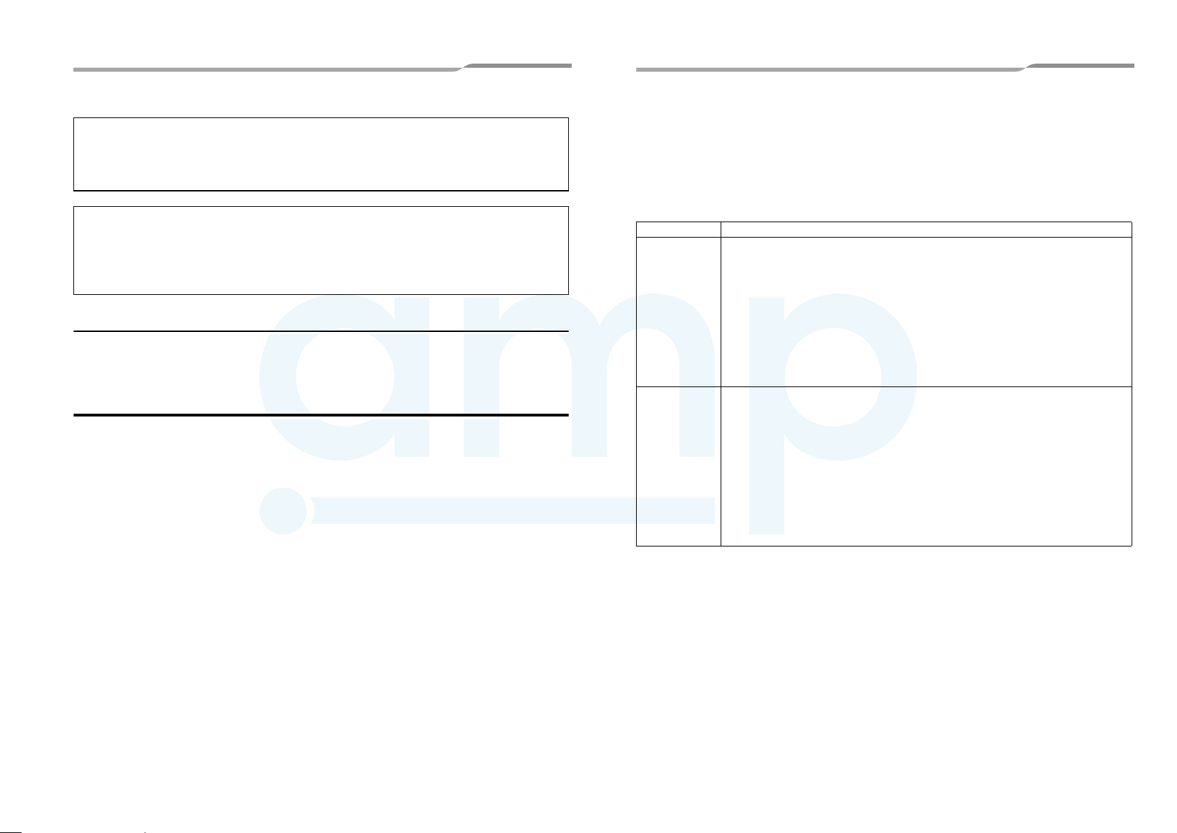
Work undertaken Protective gear worn
All types of work Protective gloves
Electrical-related work Gloves to provide protection for electricians and from heat
Work done at heights (50 cm or more) Helmets for use in industry
Transportation of heavy objects Shoes with additional protective toe cap
‘Safety’ working clothing
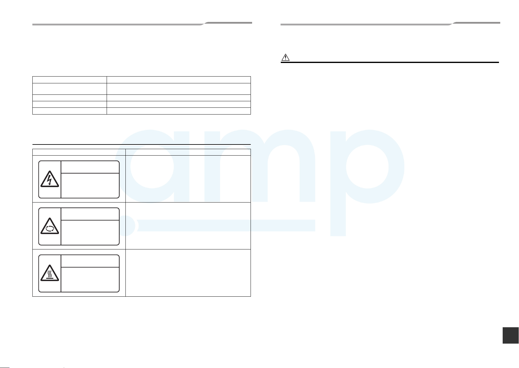
Warning Indications on the Air to Air Heat Exchanger
Warning indication Description
WARNING
ELECTRICAL SHOCK HAZARD
Disconnect all remote
electric power supplies
before servicing.
WARNING
Moving parts.
Do not operate unit with
inspection cover removed.
Stop the unit before the servicing.
CAUTION
High temperature parts.
You might get burned
when removing this cover.
WARNING
ELECTRICAL SHOCK HAZARD
Disconnect all remote electric power supplies before servicing.
WARNING
Moving parts.
Do not operate unit with inspection cover removed.
Stop the unit before the servicing.
CAUTION
High temperature parts.
You might get burned when removing this cover.
1 Precautions for Safety
WARNING
General
• Before starting to install the Air to Air Heat Exchanger, read carefully through the Installation Manual, and follow its
instructions to install the Air to Air Heat Exchanger.
• Only a qualified installer(*1) or qualified service person(*1) is allowed to install the Air to Air Heat Exchanger. If the
Air to Air Heat Exchanger is installed by an unqualified individual, a fire, electric shocks, injury, water leakage, noise
and/or vibration may result.
• If using separately sold products, make sure to use Toshiba specified products only. Using unspecified products may
cause fire, electric shock, water leak or other failure.
• Before opening the electrical control cover or inspection cover of the Air to Air Heat Exchanger, set the circuit breaker
to the OFF position. Failure to set the circuit breaker to the OFF position may result in electric shocks through contact
with the interior parts. Only a qualified installer(*1) or qualified service person(*1) is allowed to remove the electrical
control cover or inspection cover of the Air to Air Heat Exchanger and do the work required.
• Before carrying out the installation, maintenance, repair or removal work, set the circuit breaker to the OFF position.
Otherwise, electric shocks may result.
• Place a “Work in progress” sign near the circuit breaker while the installation, maintenance, repair or removal work
is being carried out. There is a danger of electric shocks if the circuit breaker is set to ON by mistake.
• Only a qualified installer(*1) or qualified service person(*1) is allowed to undertake work at heights using a stand of
50 cm or more or to remove the electrical control cover or inspection cover of the Air to Air Heat Exchanger to
undertake work.
• Wear protective gloves and safety work clothing during installation, servicing and removal.
• When working at heights, use a ladder which complies with the ISO 14122 standard, and follow the procedure in the
ladder’s instructions. Also wear a helmet for use in industry as protective gear to undertake the work.
• When cleaning the filter or heat exchange element of the Air to Air Heat Exchanger, set the circuit breaker to OFF
without fail, and place a “Work in progress” sign near the circuit breaker before proceeding with the work.
• When working at heights, put a sign in place so that no-one will approach the work location, before proceeding with
the work. Parts and other objects may fall from above, possibly injuring a person below.
• The Air to Air Heat Exchanger must be transported in stable condition. In case an accident such as dropping of the
unit occurs while transporting the Air to Air Heat Exchanger, contact the dealer .
• Do not move or repair any unit by yourself. There is high voltage inside the unit. You may get electric shock when
removing the cover and main unit.
• Do not modify the products. Do not als o disa ssembl e or modi fy the par ts. It may caus e a fire, electr ic shoc k or inj ury.
• Confirm whether there is a risk of the Air to Air Heat Exchanger falling down during maintenance or repairing work.
• Before opening the Supply/Exhaust air grill, set the circuit breaker to the OFF position. Otherwise, your hand may be
caught in the rotating parts inside and an injury may result.
Selection of installation location
• Do not install the Air to Air Heat Exchanger in a location that may be subject to a risk of expire to a combustible gas.
If a combustible gas leaks and becomes concentrated around the unit, a fire may occur.
• When transporting the Air to Air Heat Exchanger, wear shoes with additional protective toe caps, protective gloves
and other protective clothing.
• When transporting the Air to Air Heat Exchanger, do not take hold of the bands around the packing carton. You may
injure yourself if the bands should break.
• Install the Air to Air Heat Exchanger at least 2.5 m above the floor level since otherwise the users may injure
themselves or receive electric shocks if they poke their fingers or other objects into the Air to Air Heat Exchanger
while it is running.
• Do not place any combustion appliance in a place where it is directly exposed to the wind of Air to Air Heat Exchanger,
otherwise it may cause im perfect combustion.
• Use a hand track or forklift to carry the unit. When carrying it by human power, have four persons or more; otherwise,
you may strain your back.
Installation
• When the Air to Air Heat Exchanger is to be suspended, the designated hanging bolts (M10 to M12) and nuts (M10
to M12) must be used.
• Install the Air to Air Heat Exchanger at enough strong places to withstand the weight of the unit. If the strength is not
enough, the unit may fall down resulting in injury.
• Follow the instructions in the Installation Manual to install the Air to Air Heat Exchanger. Failure to follow these
instructions may cause the product to fall down or topple over or give rise to noise, vibration, water leakage, etc.
EN
3-EN 4-EN
–2–

5-EN 6-EN
AMP Air Conditioning
www.ampair.co.uk | sales@ampair.co.uk
Air to Air Heat Exchanger
Installation Manual
–3–
Air to Air Heat Exchanger
Installation Manual
Electrical wiring
• Only a qualified installer(*1) or qualified service person(*1) is allowed to carry out the electrical work of the Air to Air
Heat Exchanger. Under no circumstances must this work be done by an unqualified individual since failure to carry
out the work properly may result in electric shocks and/or electrical leaks.
• When repairing the electrical parts or undertaking other electrical jobs, wear gloves to provide protection for
electricians and from heat. Failure to wear this protective gear may result in burn.
• Use wiring that meets the specifications in the Installation Manual and the stipulations in the local regulations and
laws. Use of wiring which does not meet the specifications may give rise to electric shocks, electrical leakage,
smoking and/or a fire.
• Connect earth wire. (Grounding work)
Incomplete earthing causes an electric shock.
• Do not connect earth wires to gas pipes, water pipes, and lightning rods or earth wires for telephone wires.
• After completing the repair or relocation work, check that the earth wires are connected properly.
• Install a circuit breaker that meets the specifications in the installation manual and the stipulations in the local
regulations and laws. Use an exclusive power supply circuit for the Air to Air Heat Exchanger at the rated voltage.
• Install the circuit breaker where it can be easily accessed by the agent.
• When installing the circuit breaker outdoors, install one which is designed to be used outdoors.
• Under no circumstances must the power cable be extended. Connection trouble in the places where the cable is
extended may give rise to smoking and/or a fire.
• Electrical wiring work shall be conducted according to law and regulation in the community and installation manual.
Failure to do so may result in electrocution or short circuit.
• When carrying out electric connection, use the wire specified in the Installation Manual and connect and fix the wires
securely to prevent them applying external force to the terminals. Improper connection or fixing may result in fire.
Test run
• Before operating the Air to Air Heat Exchan ger after havin g completed the work, check that the electrical control cover
and inspection cover are closed, and set the circuit breaker to the ON position. You may receive an electric shock if
the power is turned on without first conducting these checks.
• When there is some kind of trouble (such as when an error display has appeared, there is a smell of burning,
abnormal sounds are heard, or water is leaking) has occurred in the Air to Air Heat Exchanger, do not touch the Air
to Air Heat Exchanger yourself but set the circuit breaker to the OFF position, and contact a qualified service person.
Take steps to ensure that the power will not be turned on (by marking “out of service” near the circuit breaker, for
instance) until qualified service person arrives. Continuing to use the Air to Air Heat Exchanger in the trouble status
may cause mechanical problems to escalate or result in electric shocks, etc.
• After the work has finished, use an insulation test er set (500V Megger) to check the resistance is 1 MΩ or more
between the charge section and the non-charge metal section (Earth section). If the resistance value is low, a disaster
such as a leak or electric shock is caused at user’s side.
• Upon completion of the installation work, check the insulation resistance. Then conduct a test run to check that the
Air to Air Heat Exchanger is operating properly.
Explanations given to user
• Upon completion of the installation work, tell the user where the circuit breaker is located. If the user does not know
where the circuit breaker is, he or she will not be able to turn it off in the event that trouble has occurred in the Air to
Air Heat Exchanger.
• After the installation work, follow the Owner’s Manual to explain to the customer how to use and maintain the unit.
• If there is a danger of the Air to Air Heat Exchanger falling, do not approach the Air to Air Heat Exchanger but set the
circuit breaker to the OFF position, and contact a qualified service person(*1) to have the repairs done. Do not set
the circuit breaker to the ON position until the repairs are completed.
Relocation
• Only a qualified installer(*1) or qualified service person(*1) is allowed to relocate the Air to Air Heat Exchan ger. It is
dangerous for the Air to Air Heat Exchanger to be relocated by an unqualified individual since a fire, electric shocks,
injury, water leakage, noise and/or vibration may result.
• The external air intake opening should be positioned away from the exhaust openings of combustion gases. The
intake of such gases could cause a lack of oxygen in the room.
The external air intake opening should not be pos itioned where discharged air may directly enter it.
A situation like this will lead to the room being contaminated and this may pose a health risk.
• Netting or something similar should be provided at the external air intake opening to prevent birds or other things
interfering with the unit.
• Nests or other foreign objects should be removed. That c ould cause a lack of oxygen in the room.
• To pierce the metal duct through the metal lath or the wire lath or the metal plate of the wooden facility, do not forget
to insulate electrically between the duct and the wall. Otherwise, it would cause an electric shock or an electric
leakage.
• Install the outdoor duct in a falling gradient toward the outside so as to prevent water from coming in. If it is not
installed so, the building is likely to be flooded, wetting the household effects.
• Heat-insulate the outdoor duct (including the indoor side, if necessary) to prevent dewing. If heat insulation is not
adequate, water likely goes indoor and wets the household properties.
• When it is high humid and high temperature inside the ceiling, a ventilation system must be installed inside the ceiling.
Otherwise, it could cause a fire or an electric leakage.
• Install the power line and the connecting line with accuracy so the power source cover may not float. If the installation
of the electrical control cover is inappropriate, the pin connection area is likely to cause a heat generation, a fire and
an electric shock due to dust or powder.
• Do not use the unit at the other voltages than the rated one. It could cause a fire or an elec tric sho ck.
• Do not install the unit in locations with large amounts of oily smoke, such as food preparation areas. It could cause a
fire.
• Do not install the unit at the place of a high temperature or a flame.
It could cause a heat generation or a fire.
• Do not install in locations with high humidity, such as close to bathroom or other similar environment. It could cause
an electric shock or an electric leakage or other troubles.
• Install an earth leakage breaker that is not tripped by shock waves.
If an earth leakage breaker is not installed, an electric shock may be caused.
• Do not install the unit and inside air int ake in a place such as a machin e factor y, chemi cal pl ant, or r esearc h insti tute,
where acids, alkaline, organic solvents, or coating materials are handled and toxic gases and/or corrosive gases may
be produced.
Otherwise gas poisoning may occur and/or the inside of the unit may be eroded or deteriorated. The deterioration
and erosion may result in an fire.
• After installation, switch off the circuit breaker for safety if the unit will not be used for a long time.
• Attach the parts such as the inspection cover securely.
Disposal
Dispose of Air to Air Heat Exchanger in accordance with the 2002/96/EC Directive WEEE (Waste Electrical and
Electronic Equipment).
(*1) Refer to the “Definition of Qualified Installer or Qualified Service Person.”
CAUTION
To Disconnect the Appliance from Main Power Supply.
• Means for disconnection having a contact separation in all poles at least 3 mm must be incorporated in the fixed
wiring in accordance with the wiring rules.
The installation fuse (All Types Can Be Used) must be used for the power supply line of this Air to Air
Heat Exchanger.
Air to Air Heat Exchanger
AMP Air Conditioning
www.ampair.co.uk | sales@ampair.co.uk
Installation Manual
Air to Air Heat Exchanger
Installation Manual
2 Accessory Parts
Name Quantity Shape Usage
Installation manual 1 — (Hand it to the customers.)
CD-ROM (Owner’s manual
and Installation manual)
Owner's manual 1 — (Hand it to the customers.)
Adapter 4 Connection parts for the duct
Screw 16/24 Screws for attaching the adapter
1—
(For other languages that do not appear in this manual, please refer
to the enclosed CD-ROM.)
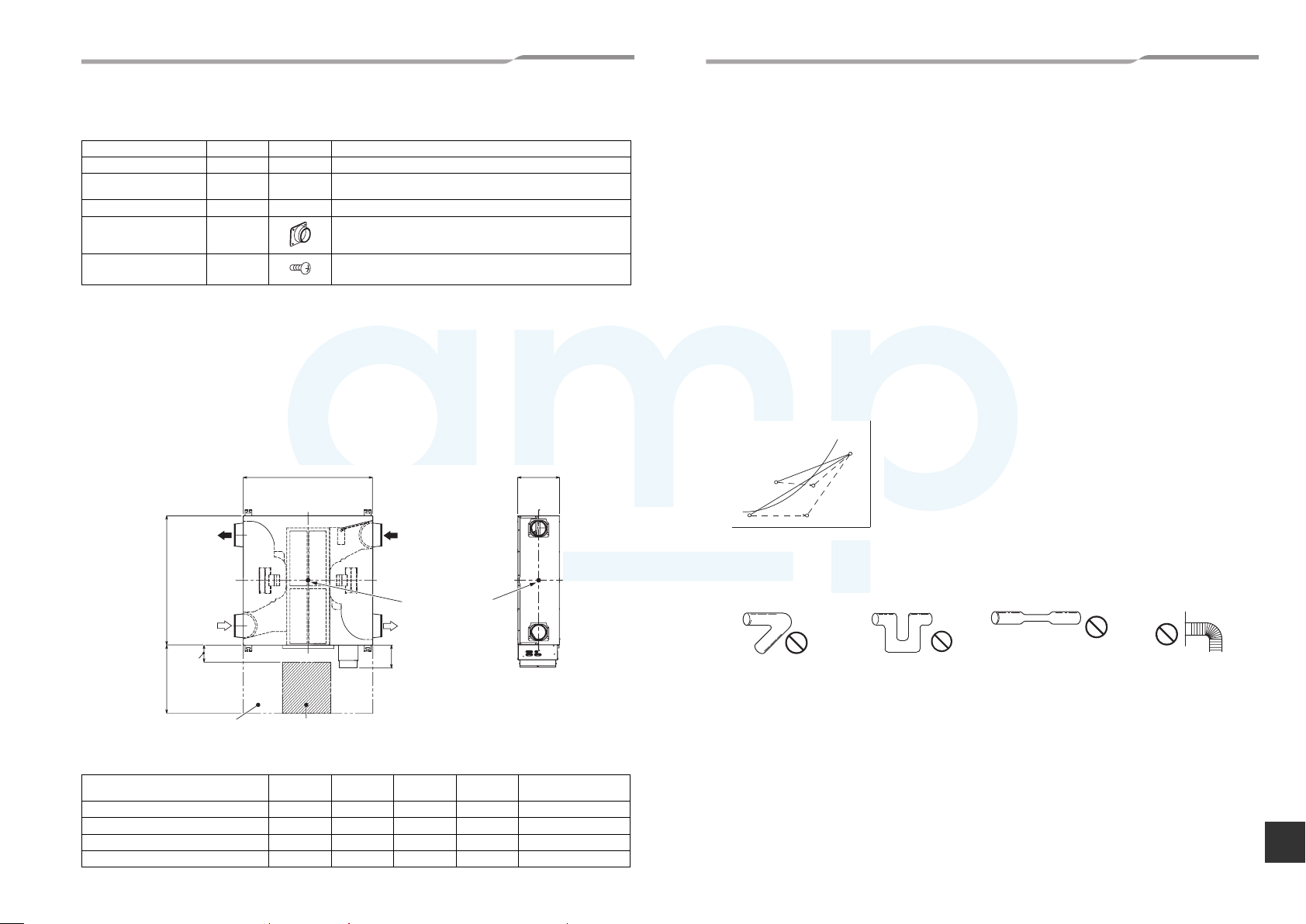
3 Cautions for Installation
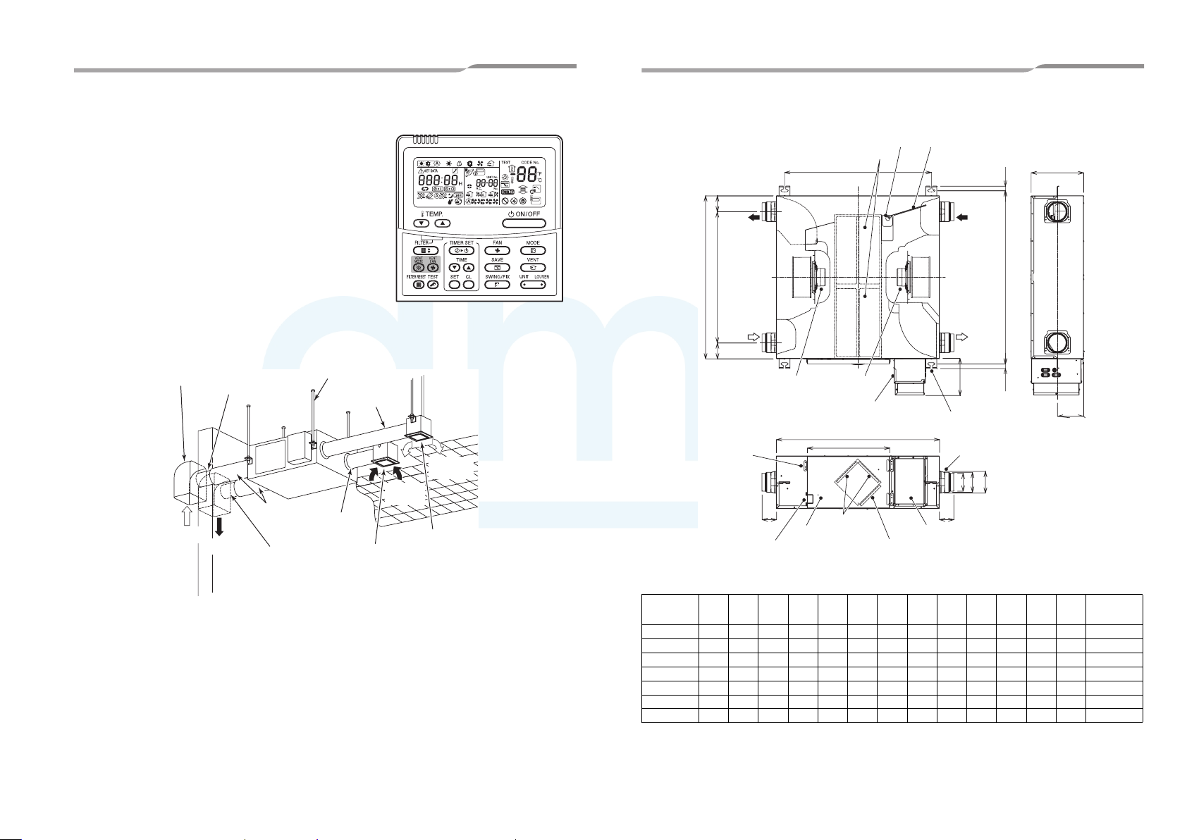
Make the inspection opening at the specific place on the ceiling so the constant cleaning or the equipment checking
of filter and heat exchange element can be performed.
• The inspection opening shown below is necessary to clean the heat exchange element and th e filt er as
required. If not cleaned, they are likely to get clogged, resulting in degradation of performance.
• Use forklift to carry in the Air to Air Heat Exchanger units and use winch or hoist at installation of them.
Unit: mm
B C
EA
(Exhaust
air)
Outdoor side
A
OA
(Outdoor
air)
150 to
250
600 or more
For the inspection of Filters,
Heat Exchange Elements,
Fans, Motors and Damper.
Inspection Opening 450 × 450
or more
RA (Return air)
Indoor side
Centre of gravity
SA (Supply air)
200
• Helmet must be worn to protect your head from falling objects.
Especially, when you work under an inspection opening, helmet must be worn to protect your head from
falling objects from the opening.
• Observe the following conditions when using the Air to Air Heat Exchanger.
Installation requirements : Temperature range −10°C to +40°C, relative humidity 80% or less
Outdoor air conditions : Temperature range −15°C to +43°C, relative humidity 80% or less
Return air conditions : Temperature range +5°C to +40°C, relative humidity 80% or less
Do not install the Air to Air Heat Exchanger in a place where flames can come into contact with the unit.
If the Air to Air Heat Exchanger is used for a long time without observing the conditions above, deterioration or
deformation of resin parts will occur and a malfunction may result.
• Dewing and frosting.
• In cold regions, the surface of the unit or the duct connector may be affected by condensation or frosting
depending on the outdoor air conditions or temperature/humidity of the ceiling cavity even though the
conditions for use are observed. In this case, add a heat insulator.
• Do not install the unit in a place where there is something that must not become wet. Depending on the
temperature or humidity of outdoor air and the installation place, water droplets may fall from the unit.
• As shown in the figure to the below, suppose a high temp absorbing air condition A and a low temp absorbing
air condition B are plotted on the air line figure, then a high temp a ir A is heat-exchanged by the unit and goes
out of the saturation curve as shown by Point C. In this case, the unit will be dewed o r frosted . To avoid th is,
heating a low temp air B up to B’ is required so as to get C’ below the saturation curve, before usin g the unit.
e
v
r
u
C
n
o
i
t
a
r
u
A
at
S
C
B
Dry-bulb temperature (°C)
C'
B'
Absolute humidity (kg/kg’)
• Refrain from the following duct installation works.
1) Excessive bending 2) Multi-times bending 3) Making the connecting duct
smaller
4) Bending near the exhaust air
duct
• Do not install it near the water-heater
• Do not use in bathrooms or food preparation areas or in similar condition place.
If the unit is used at the place of much soot and high humidity large amounts of oily smoke, the filter or the
heat exchange element gets clogged and it will be disable to be use.
• Duct length must be longer than 850 mm.
Model No. A (mm) B (mm) C (mm) Weight (kg)
VN-M150HE, M250HE 900 900 290 36 2
VN-M350HE 900 900 290 38 2
VN-M500HE, M650HE 1140 1140 350 53 2
VN-M800HE, M1000HE 1189 1189 400 70 2
7-EN 8-EN
Heat exchange
element
EN
–4–
9-EN 10-EN
AMP Air Conditioning
www.ampair.co.uk | sales@ampair.co.uk
Air to Air Heat Exchanger
Installation Manual
–5–
Air to Air Heat Exchanger
Installation Manual
4 Separately Sold Parts
• Wired remote controller (for the Air to Air Heat Exchanger)
NRC-01HE (Sold separately)
Up to 8 units of the Air to Air Heat Exchanger can be operated us ing
this remote controller.
5 Reference Diagram
Pipe hood
OA (Outdoor air)
Outdoor air
intake duct
EA (Exhaust air)
Heat insulation
material
Hanging bolt
Exhaust air
duct
Supply air duct
Return air
intake duct
Room intake
opening
(Supply/
Exhaust Air
grille)
RA (Return
air)
Inside supply opening
(Supply/Exhaust Air grille)
SA (Supply
air)
6 Model List
Heat exchange element (2)
CC
EA
(Exhaust air)
Outdoor
A
B
side
OA
(Outdoor air)
Motor
(Exhaust air)
Fixed part of
inspection cover
H H
Fixing lever
Model nameABCDE FGH I JKLM
VN-M150HE 900 724 88 810 957 900 454 80 Ø98 Ø110 121 290 145 Ø100
VN-M250HE 900 670 115 810 957 900 454 97 Ø145 Ø158 162 290 145 Ø150
VN-M350HE 900 670 115 810 957 900 454 97 Ø145 Ø158 162 290 145 Ø150
VN-M500HE 1140 800 170 1050 1197 1140 454 80 Ø195 — Ø212 350 175 Ø200
VN-M650HE 1140 800 170 1050 1197 1140 454 80 Ø195 — Ø212 350 175 Ø200
VN-M800HE 1189 800 195 1099 1246 1189 454 85 Ø245 — Ø262 400 200 Ø250
VN-M1000HE 1189 800 195 1099 1246 1189 454 85 Ø245 — Ø262 400 200 Ø250
(Supply Air)
Inspection cover
Damper motor
D
Motor
Electrical control base
F
G
Filter (x 2)
High efficiency filter
(One for each element)
(sold separately)
Damper
RA
(Return air)
Indoor
side
SA
(Supply air)
200
Hanging bracket (4)
4 - 13 X30 Oval hole
Adapter (4)
I
J
K
Electrical control cover
25
E
25
L
M
Unit: mm
Applicable
duct nominal
diameter
Air to Air Heat Exchanger
AMP Air Conditioning
www.ampair.co.uk | sales@ampair.co.uk
Installation Manual
Air to Air Heat Exchanger
Installation Manual
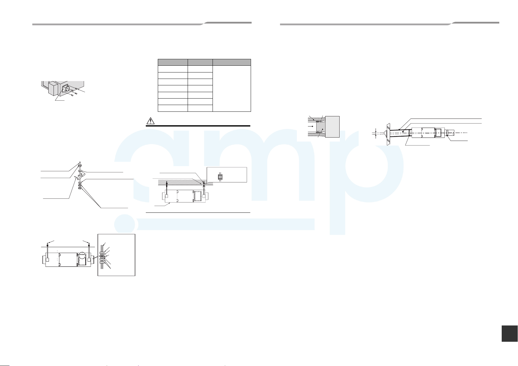
7 Installation
Attaching the adapter
• Attach the adapter to the unit using the accessory
screws (4 or 6).
Screws (accessory:
Adapter
Attaching the washer and the
nut
1) Preparation of the hanging bolt, nut, and
washer is required.
2) Attach the washer and the nut to the hanging
bolt (see the table on the below) according to
the diagram on the below.
Hanging bolt
(M10 or M12)
Nut (M10 or M12)
Hanging bracket
4 or 6 screws)
Washer (M10 or M12)
Washer (M10 or M12)
Use the washer just under
the hanging bracket to
prevent the bolt from
falling off.
Nut (M10 or M12)
Model name Weight (kg) Hanging bolt
VN-M150HE 36
VN-M250HE 36
VN-M350HE 38
VN-M500HE 53
VN-M650HE 53
VN-M800HE 70
VN-M1000HE 70
M10, M12
CAUTION
• Use a commercially available vibration-proof fixture
when the unit is installed in a place where preventing
vibration is necessary.
• Leave a space of 450mm x 450mm or more for
checking the filter, heat exchanging element, power
source, or motor. Refer to “Cautions for Installation”
for the location of the space required.
Hanging bolt
Vibration-proof fixture
Unit
Vibration-proof fixture
Duct Installation
• Duct installation is necessary to protect against access to live parts, rain water or contact with moving parts.
• Seal the junction of an adaptor and a duct with an aluminium tape firmly to prevent any air leakage.
• The room intake opening should be positioned as far as possible from the indoor supply opening.
• Use the specified ducts. (See the Model List)
• Install two outdoor ducts so they will be in the down gradient toward outdoor to prevent water from coming in.
(Gradient: 1/100~1/50) (See the figure below)
Heat-insulate two outdoor ducts (including outdoor air and exhaust air duct) to prevent dewing.
(Material: Glass Wool, Thickness-25mm) (See the figure below)
To pierce the metal duct through the metal lath or the wire lath or the metal plate of the wooden facility, insulate
electrically between the duct and the wall. (Refer to the laws and regulations of the country concerned and the
technical standard.)
Adapter
Aluminium tape
Unit
Slope
(1/100 to 1/50)
Heat insulator
Duct
• It is recommended that an electric damper is used together with the Air to Air Heat Exchanger, as wind may enter
the room while the unit is not in operation in windy places.
Heat insulator
(Insulates the adapter and the aluminium tape)
Outdoor air intake duct, Exhaust air duct
Aluminium tape
Aluminium tape
Fixing the unit
Hanging bolt
(M10 or M12)
Hanging bolt
Nut
Washer
Hanging
bracket
Washer
Nut
Cautions installing unit body
upside down
• The hanging bracket does not need to be replaced.
• The printed image is reversed.
1) Hang the hanging bracket on the hanging bolt,
then adjust the nut so that the unit is level.
2) Use a double nut and fasten it firmly so that the
nut does not become loose.
• If the unit is not installed properly, it will vibrate
and may pose a hazard.
• If the unit is not level, the damper unit will not
work properly.
• Install the unit firmly enough to support its own
weight.
11-EN 12-EN
–6–
EN
13-EN 14-EN
AMP Air Conditioning
www.ampair.co.uk | sales@ampair.co.uk
Air to Air Heat Exchanger
Installation Manual
–7–
Air to Air Heat Exchanger
Installation Manual
8 Electric Wiring
WARNING
1. Using the specified wires, ensure to connect the wires, and fix wires securely so that the external tension to
the wires do not affect the connecting part of the terminals.
Incomplete connection or fixation may cause a fire or other troubles.
2. Connect earth wire. (grounding work)
Incomplete earthing cause an electric shock.
Do not connect earth wires to gas pipes, water pipes, lightning rods or earth wires for telephone wires.
3. Appliance shall be installed in accordance with national wiring regulations.
Capacity shortage of power circuit or incomplete installation may cause an electric shock or a fire.
CAUTION
• If incorrect/incomplete wiring is carried out, it will cause an electrical fire or smoke.
• Install an earth leakage breaker that is not tripped by shock waves.
If an earth leakage breaker is not installed, an electric shock may be caused.
• Use the cord clamps attached to the product.
• Do not damage or scratch the conductive core and inner insulator of power and communication wires when peeling
them.
• Use the power and communication wire of specified thickness, type, and protective devices required.
• Do not connect 220-240V power to the communication terminal blocks ( , , , ) for control wiring.
(Otherwise, the system will fail.)
REQUIREMENT
• For power supply wiring, strictly conform to the Local Regulation in each country.
• After connecting wires to the terminal blocks, provide a trap and fix wires with the cord clamp.
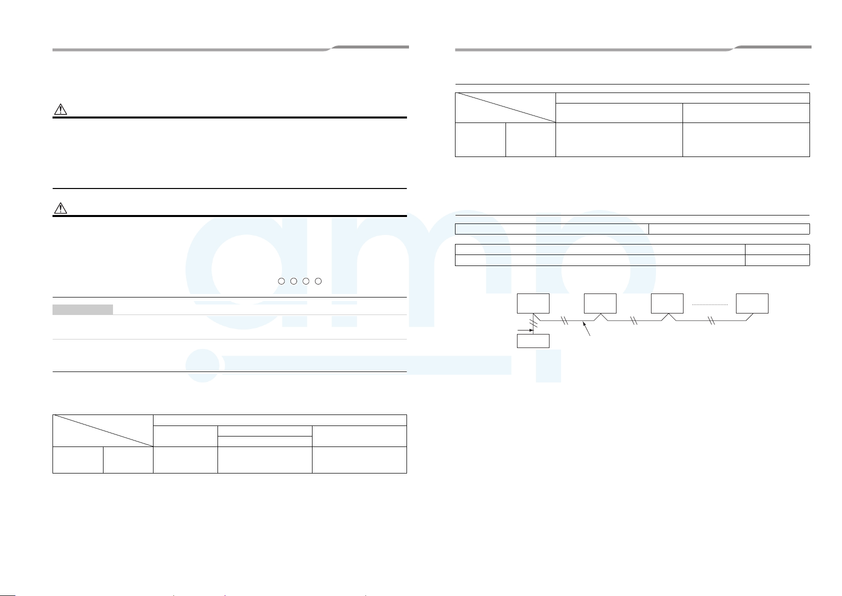
Power and wiring Specifications
Power supply wire and communication wire should be locally procured.
U3U4A B
Communication wire
Item
Model name VN-
Air to Air Heat
Exchanger
*2:
• The length of the communication wire is the total length of the outdoor/indoor transition wire and wire of the central control
assuming that an interlocking system with the indoor unit or central control system is used.
• To prevent noise, use a 2 core shielded wire.
M150HE to
M1000HE
Central control wire (*2) Remote controller wire
2-core, non-polarity
Shielded wire
(Up to 1000m) 1.25 mm
(Up to 2000m) 2.0 mm
Communication wire
2
2
2-core, non-polarity
2
to 2.0 mm2
0.5 mm
Remote controller wiring
Remote controller wiring, remote controller inter-unit wiring 2-core, non-polarity: 0.5 mm
Total wire length of remote controller wiring and remote controller inter-unit wiring = L + L1 + L2 + ··· Ln Up to 500mm
Total wire length of remote controller inter-unit wiring = L1 + L2 + ··· Ln Up to 200mm
On the outside of the uni t, do not all ow the wire fo r the remote c ontroller (co mmunication wi re) and the w ire for AC220-24 0V to come into contact
or put them together in one electrical conduit; otherwise, the control system may have trouble due to noise.
Indoor unit
wiring
L
Remote
controller
Remote controller
* The total length of the remote controller inter-unit wiring is the same for both between the indoor units and
between the Air to Air Heat Exchanger.
Indoor unit
L1 L2 Ln
Remote controller inter-unit wiring
Air to Air
Heat
Exchanger
(Up to 8 units)
2
to 2.0 mm2
Air to Air
Heat
Exchanger
See the table below for the power supply specifications. If the capacity is too small, the unit will suffer from
overheating or burnout.
Item
Model name VN-
Air to Air Heat
Exchanger
*1: Prepare the exclusive power supply for the Air to Air Heat Exchanger
M150HE to
M1000HE
Power supply
220V-240V~, 50Hz
220V~, 60Hz
Power supply for Air to Air Heat Exchanger (*1)
Circuit breaker (switch)
Current rating (Fuse rating)
15A
Power supply wire
1.5 mm
(H07 RN-F or 60245 IEC 66)
3-core,
2
or 2.5 mm
2

Air to Air Heat Exchanger
A
AMP Air Conditioning
www.ampair.co.uk | sales@ampair.co.uk
Installation Manual
Air to Air Heat Exchanger
Installation Manual
Connection diagram
Gray Light blue
M
FM1
1~
Connector
(White)
White
C C
White
Blue
Black
Connector
Orange
(White *6)
White
3
23
13
43F12
43F11
5
5
White
White
Red
Air to Air Heat
Exchanger
Earth
Code Part name
CN*** Connector
F01 Fuse
FM1 Air supplying motor
FM2 Air exhausting motor
DAM Damper motor
TRA TRA sensor
M
1~
Connector
(Black)
Yellow
Blue
Connector
Brown
(Red *6)
Red
43F22
55
White
White
Red
S(N)R(L)
Power supply for the Air
to Air Heat Exchanger
220-240V~, 50Hz
220V~, 60Hz
132
FM2
Yellow
43F21
Red
White
7
43F12
8
P01
Black
CN701
Black
TB1
1
(White)
F01
T3.15A
250V~
1
3
CN67
(Black)
represents the connector to switch between
Extra High and High.
TOA TOA sensor
RY701, RY702 Relay for air supplying motor
RY704, RY705 Relay for air exhausting motor
TB1 Terminal block (power supply)
TB2 Terminal block (communication)
TB3 Terminal block (external output)
777
43F21
43F11 43F22
888
Gray
Yellow
Blue
Light blue
Pink
Brown
3513
RY701
CN702
5
(Red)
Indoor control
RY705
RY702
circuit board
MCC1615
RY704
Code Part name
1. The dotted line represents a wire procured locally, and the dashed line represents an option sold separately.
2. represents a terminal block, represents a c onne ction terminal, and represents a connector on
the printed circuit board.
3. represents a protective earth.
4. represents a printed circuit board.
5. Using a no voltage a-contact input of the external input (sold separately), the following operations are available:
Between 1 and 2: Selecting the remote controller operation (Invalid/Valid)
Between 1 and 3: Adjusting the ventilation fan speed (Low/High)
Between 1 and 4: Selecting the ventilation mode (Bypass mode/Heat exchange mode)
Between 1 and 5: Operation (ON/OFF)
Use a microcurrent contact (DC12V, 1mA). In addition, ON/OFF operation is possible when using a voltage of
DC12V or 24V.
6. Blue wire (High) is connected as factory default. To switch to “Extra High”, connect black wire’s connector
instead of blue.
7. When the temperature of the outdoor air is below -10°C, the unit runs in the cold mode (the ventilator for air
supply runs intermittently). The unit cannot run when the temperature of the outdoor air is below -15°C. The
ventilator for air supply stops running and the ventilator for air exhaust also stops depending on the settings.
8. Even if “Bypass mode” is selected manually, the unit switches to “Heat exchange mode” automatically to prevent
condensation when the temperature of the outdo or air is below 15°C. However, “Byp ass mode” is still displayed.
+
+
M
2134
CN760
(White)
DAM
6
65
Power
supply
External output
(220-240V~, under 1A each)
Operation output
Common
External damper output
12 45
1
Abnormal/Bypass mode ou tpu t
3
TB3
White
Yellow
Blue
Black
Red
CN704
3 975
RY710
RY709
RY708
SW701
DC20V
DC12V
DC 5V
ON
OFF
SW702
ON
OFF
1
4322341
Wiring for central control Wiring for the remote
Code Part name
SW301, SW701
SW702, SW703
43F11, 43F12 Relay for air supplying motor
43F21, 43F22 Relay for air exhausting motor
*5 External input (sold
separately)
No voltage a-contact input
1 Common
2 Remote controller operation
3 Ventilation fan speed
4 Ventilation mode
5 Operation
Voltage DC (12V, 24V) input
5
213
1
4
52
CN705
CN706
1
Blue Blue
U3
DIP switch
CN105
(Brown)
CN106
(White)
CN041
2
3
1
Black
Black
U4
BA
controller
BA
SW301
ON
OFF
SW703
ON
OFF
CN040
(Blue) (Blue)
TB2
1
2
2
1
t°
2
1
t°
2
Wired remote
controller (sold
separately)
TR
TOA
Switches and connectors on the circuit board
Remove the 4 screws to detach the electrical control cover.
* Refer to "9. Installation Method for Each System Configuration" on page 10 about setting the switch.
Electrical control base
Screws (x 4)
Electrical control cover
Changeover switch
for the central
control address
SW703 (No. 3)
Fix: ON
Auto: OFF
ON
OFF
1ON2 3 4 1ON2 3 4
SW702 SW703
Changeover switch for th e
indoor unit address
SW702 (No.1 to 4), 703 (No. 1
and 2)
Changeover switch
for the group
address
SW703 (No.4)
Header (Individual:
ON
Follower: OFF
Changeover switch
for the terminator
SW301 (No.1)
100Ω: ON
None: OFF
ON
OFF
1ON2
SW301
Changeover switch for
pulse/static
SW701 (No.1)
Pulse: ON
Level: OFF
Connectors for the external
input
Remote ON/OFF adapter
(NRB-1HE: sold separately)
CN705(5P)
No voltage a-contact in put
(Remote controller
operation Invalid/Valid,
fan speed Low/High,
Ventilation mode Bypass/
Heat exchange, Operation
ON/OFF)
CN706(2P)
Voltage of DC12V or 24V
(ON/OFF)
ON
OFF
1ON2
SW701
15-EN 16-EN
–8–
EN

17-EN 18-EN
AMP Air Conditioning
www.ampair.co.uk | sales@ampair.co.uk
Air to Air Heat Exchanger
Installation Manual
–9–
Air to Air Heat Exchanger
Installation Manual
Wire connection
In a central control system, connect
the copper braid shield of central
control wire (2-core shielded wire).
Communication wire
terminal block
Wiring for the central
control (U3, U4)
Wiring for the remote
controller (A, B)
Power supply terminal
block (R(L), S(N))
External output terminal
block (1, 2, 3, 4, 5)
Operation output
Common
External damper output (3-4)
Abnormal/Bypass mode
output (3-5)
U2
U1
BA
U4
U3
SR
Power supply wire Central control wire Remote controller wire
30
S(N)
R(L)
Earth line
30
40
1510
REQUIREMENT
• Pass the wires through the grommet of wiring connection holes of the Air to Air Heat Exchanger.
• Keep a margin (Approx. 100 mm) on a wire.
• The low-voltage circuit is provided for the remote controller.
• Rotate the electrical control base to open.
• Connect the power supply wire (R (L), S (N)) and the remote control wire (A, B).
• Connect the central control wire (U1/U3, U2/U4) or the external output terminal block (1 to 5) if necessary.
• Tighten the screws on the terminal board firmly, then fix the wiring on the electrical control box using the
accessory cord clamp.
• Perform earthing work.
Remote
controller wire
Central control
wire
Earth screw
Grommet
Power supply
wire
Electrical control
box
1510
Switching between Extra High and High
WARNING
• Turn off the circuit breaker before switching between Extra High and High.
When switching to Extra High, connect the black lead wire
(Extra High) to the connector.
* The blue lead wire (High) is connected as factory default.
* Connect the black lead wire both to the supplying air motor
(white connector) and the exhausting air motor (red
connector).
* Refer to “Connection diagram” for the connection method.
REQUIREMENT
• After connecting the black lead wire to the connectors, fix the
lead wires using the cord clip.
Cord clip
Blue lead wire
(High)
*Factory default
Exhaust air
(red connector)
Supply air
(white connector)
Remote Controller Wiring
• As the remote controller wire has non-polarity, there is no problem if connections to Air to Air Heat Exchanger
terminal blocks A and B are reversed.
Wiring diagram
Terminal block for remote
controller wiring of Air to Air
Heat Exchanger
A
B
Remote controller wire
(locally procured)
* For details of wiring/installation of the remote controller, refer to the Installation Manual enclosed to in the remote
controller.
Terminal block
Remote
A
controller
B
unit

Air to Air Heat Exchanger
AMP Air Conditioning
www.ampair.co.uk | sales@ampair.co.uk
Installation Manual
Air to Air Heat Exchanger
Installation Manual
9 Installation Method for Each System
Configuration
D
Central control system
(When controlling the Air to Air Heat Exchanger only)
Settings and electric wiring differ depending on the system configuration. Perform electric wring according to the
system examples shown in the table below. (Refer to page 12 to 14 for details.)
System example Operation
A
Air to Air Heat Exchanger system
(One Air to Air Heat Exchanger is used.)
Air to Air
Heat
Exchanger
AB
AB AB
Remote controller for the Air to Air
Heat Exchanger
NRC-01HE
Remote controller for air conditioner
RBC-AMS41E
B
Air to Air Heat Exchanger system
(Multiple Air to Air Heat Exchangers are used.)
Air to Air
Heat
Exchanger
C
Air to Air Heat Exchanger system linked with air
conditioners
Outdoor
unit
Air
conditioner
Air to Air
Heat
Exchanger
AB AB
AB AB
Remote controller for the Air to Ai r
Heat Exchanger
NRC-01HE
Remote controller for air
conditioner
RBC-AMS41E
U1 U2
U1 U2 U1 U2
Air
conditioner
AB AB AB
Remote controller for air conditioner
AB
RBC-AMT32E, RBC-AMS41E
Remote controller for the Air to Air Heat
Exchanger
NRC-01HE
Air to Air
Heat
Exchanger
Air to Air
Heat
Exchanger
19-EN 20-EN
• Using the remote controller for the Air to Air Heat
Exchanger NRC-01HE, the unit can be started or stopped,
control the ventilation fan speed, and select the ventilation
mode.
• If two remote controllers are used, the latter operation
overrides the former and their indications always reflect the
result of the latter operation.
* The remote controllers for the air conditioners RBC-
AMT32E are not compatible with a system in which only
the Air to Air Heat Exchanger is used. Only on/off
operation is available for RBC-AMS41E.
• Using the remote controller for the Air to Air Heat
Exchanger NRC-01HE, the unit can be started or stopped,
control the ventilation fan speed, and select the ventilation
mode.
• If two remote controllers are used, the latter operation
overrides the former and their indications always reflect the
result of the latter operation and the settings of the header
unit.
* The remote controllers for the air conditioners RBC-
AMT32E are not compatible with a system in which only
the Air to Air Heat Exchanger is used. Only on/off
operation is available for RBC-AMS41E.
• The remote controller for the air conditioner or the Air to Air
Heat Exchanger can be used to ON/OFF the whole
system.
• The remote controller for the Air to Ai r Heat Exchanger
NRC-01HE can be used to control the ventilation fan speed
and ventilation mode of the Air to Air Heat Exchanger.
• The remote controller for air conditioner RBC-AMT32E and
RBC-AMS41E cannot be used to control the ventilation fan
speed or ventilation mode of the Air to Air Heat Exchanger.
• The remote controller for the air conditioner or the Air to Air
Heat Exchanger can be used to ON/OFF the Air to Air Heat
Exchanger separately.
AB
* Setting modifications are required for separate control.
AB
Refer to "11. Advanced Control" on page 19.
• If two remote controllers are used, the latter operation
overrides the former and their indications always reflect the
result of the latter operation. In addition, the indications of
the Air to Air Heat Exchanger always reflect the setting of
the unit with the smallest indoor unit address number.
–10–
U3 U4
U3 U4 U3 U4
Air to Air
Heat
Exchanger
AB
AB
Remote controller for the Air to Air Heat Exchanger
(NRC-01HE)
Remote controller for air conditioner (RBC-AMS41E)
E
Central control system
(When controlling the air conditioner and the Air to Air Heat
Exchanger separately)
Outdoor
unit
U1 U2
U3 U4
U1 U2 U1 U2
Air
conditioner
AB
AB
Remote controller for the
air conditioner
(RBC-AMT32E, RBCAMS41E)
F
Central control system
(When controlling the air conditioner and Air to Air Heat
Exchanger together)
Outdoor
unit
U1 U2
U3 U4 U3 U4
U1 U2 U1 U2
Air
conditioner
AB AB AB
AB
System example Operation
• The central controller can be used to ON/OFF the whole
system and separately ON/OFF groups of the Air to Air
Central controller for 64/128 units/groups
(TCB-SC642TLE2, BMS-CM1280TLE)
Air to Air
Heat
Exchanger
AB
AB
U3 U4
Air
conditioner
AB
AB
Air
conditioner
Remote controller for air
conditioner
(RBC-AMT32E, RBC-AMS41E)
Remote controller for the Air to Air
Heat Exchanger (NRC-01HE)
Air to Air
Heat
Exchanger
Central controller for 64/128
units/groups
(TCB-SC642TLE2, BMSCM1280TLE)
Air to Air
Heat
Exchanger
Remote controller for the Air to Ai r
Heat Exchanger (NRC-01HE)
Remote controller for air conditioner
(RBC-AMS41E)
Central controller for 64/128
units/groups
(TCB-SC642TLE2
BMS-CM1280TLE)
Air to Air
Heat
Exchanger
AB
AB
U3 U4
AB
AB
Air to Air
Exchanger
Air to Air
Heat
Exchanger
Air to Air
Exchanger
Heat
AB
AB
AB
AB
Heat
Heat Exchangers.
• The central controller cannot be used to control the
ventilation fan speed or ventilation mode of the Air to Air
Heat Exchanger.
• If the central controller and the remote controller for the Air
to Air Heat Exchanger are used, the latter operation
overrides the former.
• The remote controller for the Air to Air Heat Exchanger
(NRC-01HE) can be used to control the ventilation fan
speed and ventilation mode of the Air to Air Heat
Exchanger.
* The remote controllers for the air conditioners (RBC-
AMT32E) cannot be used to control the group of the Air
to Air Heat Exchangers. Only on/off operation is
available for RBC-AMS41E.
• The central controller can be used to ON/OFF the whole
system and separately ON/OFF groups of air conditioners
and the Air to Air Heat Exchangers. (Air conditioners and
Air to Air Heat Exchangers are not linked in this system.)
• The central controller cannot be used to control the
ventilation fan speed or ventilation mode of the Air to Air
Heat Exchanger.
• The operation of the central controller overrides that of the
remote controllers for the Air to Air Heat Exchangers and
the air conditioners. However, the operation of the remote
controller for the Air to Air Heat Exchanger does not affect
that of the remote controller for the air conditioner and vice
versa.
• The remote controller for the Air to Air Heat Exchanger
(NRC-01HE) can be used to control the group of the air
conditioners instead of using the remote controller for the
air conditioner.
• The remote controller for the Air to Air Heat Exchanger
(NRC-01HE) can be used to control the ventilation fan
speed and ventilation mode of the group of the Air to Air
Heat Exchangers.
* The remote controllers for the air conditioners (RBC-
AMT32E) cannot be used to control the group of the Air
to Air Heat Exchangers. Only on/off operation is
available for RBC-AMS41E.
• The central controller can be used to ON/OFF the whole
system. It can also be used to ON/OFF the Air to Air Heat
Exchanger separately (*).
• The central controller cannot be used to control the
ventilation fan speed or ventilation mode of the Air to Air
Heat Exchanger.
• If three control devices are used; the central controller and
the remote controllers for the Air to Air Heat Exchanger and
the air conditioner, the latter operation overrides the former
regardless of which device is used.
• The remote controller for the Air to Air Heat Exchanger
NRC-01HE can be used to control the ventilation fan speed
and ventilation mode of the Air to Air Heat Exchanger.
• If the remote controller for the air conditioner (RBC-
AB
AMT32E and RBC-AMS41E) is used; the ventilation fan
speed or ventilation mode of the Air to Air Heat Exchanger
can not be controlled.
AB
• The remote controller for the air conditioner or the Air to Air
Heat Exchanger can be used to ON/OFF the Air to Air Heat
Exchanger separately.
* Setting modifications are required for separate control.
Refer to “"11. Advanced Control" on page 19.
EN

21-EN 22-EN
AMP Air Conditioning
www.ampair.co.uk | sales@ampair.co.uk
Air to Air Heat Exchanger
Installation Manual
–11–
Air to Air Heat Exchanger
Installation Manual
Air to Air Heat Exchanger system
System example —
Central control None
No. of Air to Air Heat
Exchangers
Operation together with the air
conditioners
Remote controller inter-unit
wiring
Central control wiring Not necessary
1.Line (system) address Fixed
2. Changing the indoor
unit address
No.1 to 4 of SW702
No.1 and 2 of SW703
3. Changing the group
address
No.4 of SW703
4.Fix/Automatic
changeover of the
central control
address
No.3 of SW703
Circuit board of the Air to Air Heat Exchanger
5. Changing the
terminator
No.1 of SW301
Checking before turning on
the power
Turning on the power Turn on the breaker of all the Air to Air Heat
Central control address
setting
A B C
1 Multiple 1 Multiple
No Yes
Not necessary Necessary
* The line (system) address is fixed as 31 for the Air to Air Heat Exchanger.
Not necessary
Factory default: 1
Necessary
Header (Individual):
ON
Complete the settings of the Air to Air Heat
Exchanger and wiring.
Exchangers.
Necessary
No duplication
Factory default: 1
Necessary
Header: ON (1unit)
Follower: OFF (the
other units)
* Settings of the
header unit reflect
the indications of
the remote
controller.
Air to Air Heat Exchanger system linked
Not necessary
Factory default: 1
Not necessary
Follower: OFF (all units)
* Settings of the follower unit with the smallest
indoor unit address number reflect the
indication of the remote controller.
Not necessary
Not necessary
None: OFF
• Complete the settings of the Air to Air Heat
Exchanger and wiring.
• Refer to the Installation Manual of the air
conditioner for the settings and wiring.
Turn on the Air to Air Heat Exchan ger first.
Refer to the Installation Manual of the air
conditioner for its power supply.
Not necessary
with air conditioners
Necessary
No duplication
Factory default: 1
Central control system
System example — —
Central control One Air to Air
No. of Air to Air Heat
Exchangers
Operation together with the air
conditioners
Remote controller inter-unit
wiring
Central control wiring Necessary (Header unit only) Not necessary
1.Line (system) address Fixed
2.Changing the indoor
unit address
No.1 to 4 of SW702
No.1 and 2 of SW703
3.Changing the group
address
No.4 of SW703
4.Fix/Automatic
changeover of the
central control
address
No.3 of SW703
Circuit board of the Air to Air Heat Exchanger
5.Changing the
terminator
No.1 of SW301
Checking before turning on
the power
Turning on the power Turn on the
Central control address
setting
D E F
Heat Exchanger
is used.
Multiple 1 Multiple 1 Multiple
Necessary Not necessary Necessary
* The line (system) address is fixed as 31 for the Air to Air Heat Exchanger.
Necessary
No duplication
Factory default: 1
Necessary
Header: ON
(1unit)
Follower: OFF
(the other units)
* Settings of the
header unit
reflect the
indications of
the remote
controller.
Necessary
100Ω: ON
(1 header unit
only)
Complete the
settings of the Air
to Air Heat
Exchanger and
wiring.
breaker of all the
Air to Air Heat
Exchangers.
Refer to the Installation Manual of the central control device.
When controlling the air conditioner
and the Air to Air Heat Exchanger
separately
No Yes
Not necessary
Factory default: 1
Necessary
Header
(Individual): ON
*Refer to the Installation Manual of the central control device.
Not necessary
OFF
* Adjust settings on the air conditioner.
• Complete the settings of the Air to Air Heat Exchanger and wiring.
• Refer to the Installation Manual of the air conditioner for the settings and
wiring.
Turn on the Air to Air Heat Exchanger first. Refer to the Installation Manual
of the air conditioner for its power supply.
Necessary
No duplication
Factory default: 1
Necessary
Header: ON
(1unit)
Follower: OFF
(the other units)
* Settings of the
header unit
reflect the
indications of
the remote
controller.
Not necessary
Auto: OFF
When controlling the air conditioner
and Air to Air Heat Exchanger
together
Not necessary
Factory default: 1
Not necessary
Follower: OFF (all units)
* Settings of the follower unit with
the smallest indoor unit address
number reflect the indication of the
remote controller.
Necessary
No duplication
Factory default: 1

Air to Air Heat Exchanger
AMP Air Conditioning
www.ampair.co.uk | sales@ampair.co.uk
Installation Manual
Air to Air Heat Exchanger
Installation Manual
Changing the group address, indoor unit address, and central
control address
◆ About the switches on the circuit board of the Air to Air Heat Exchanger
SW702 SW703
Changing the indoor unit address
●: ON -: OFF
When there are multiple Air to Air
Heat Exchangers, do not duplicate
the value between No.1 to No.4 of
SW702 and between No.1 and No.2
of SW703. (Factory default: 1)
ON
OFF
1ON2 3 4 1ON2 3 4
Indoor unit address switch (¦: ON —: OFF)
Address switch number
SW702 SW703 SW702 SW703 SW702 SW703 SW702 SW703
1 2 3 4 1 2 1 2 3 4 1 2 1 2 3 4 1 2 1 2 3 4 1 2
Address
1 ——————17————¦ — 33—————¦ 49————¦¦
2 ¦ —————18 ¦ ———¦ — 34 ¦ ————¦ 50 ¦ ———¦¦
3—¦ ————19 — ¦ ——¦ — 35 — ¦ ———¦ 51 — ¦ ——¦¦
4 ¦¦————20 ¦¦——¦ — 36 ¦¦———¦ 52 ¦¦——¦¦
5——¦ ———21 — — ¦ — ¦ — 37 — — ¦ ——¦ 53 — — ¦ — ¦¦
6 ¦ — ¦ ———22 ¦ — ¦ — ¦ — 38 ¦ — ¦ ——¦ 54 ¦ — ¦ — ¦¦
7—¦¦———23 — ¦¦— ¦ — 39 — ¦¦——¦ 55 — ¦¦— ¦¦
8 ¦¦¦———24 ¦¦¦— ¦ — 40 ¦¦¦——¦ 56 ¦¦¦— ¦¦
9 ———¦ ——25 — — — ¦¦— 41 — — — ¦ — ¦ 57———¦¦¦
10 ¦ ——¦ ——26 ¦ ——¦¦— 42 ¦ ——¦ — ¦ 58 ¦ ——¦¦¦
11 — ¦ — ¦ ——27 — ¦ — ¦¦— 43 — ¦ — ¦ — ¦ 59 — ¦ — ¦¦¦
12 ¦¦— ¦ ——28 ¦¦— ¦¦— 44 ¦¦— ¦ — ¦ 60 ¦¦— ¦¦¦
13 — — ¦¦——29 — — ¦¦¦— 45 — — ¦¦— ¦ 61 — — ¦¦¦¦
14 ¦ — ¦¦——30 ¦ — ¦¦¦— 46 ¦ — ¦¦— ¦ 62 ¦ — ¦¦¦¦
15 — ¦¦¦——31 — ¦¦¦¦— 47 — ¦¦¦— ¦ 63 — ¦¦¦¦¦
16 ¦¦¦¦——32 ¦¦¦¦¦— 48 ¦¦¦¦— ¦ 64 ¦¦¦¦¦¦
Address switch number
Address
Address
Changing the group address
Header (Individual): ON Follower: OFF
• When the system equipped with the Air to Air
Heat Exchanger(s) only is used, s et only one
unit as the header unit.
• When the system equipped with the Air to Air
Heat Exchanger and air conditio ners is
used, be sure to set all the Air to Air Heat
Exchangers as follower units . (Factory
default: Follower)
Changing the central control address
Fixed: ON Auto: OFF
The settings do not need to be adjusted.
(Leave the value OFF.)
Address switch number
Address switch number
Address
Installing two remote controllers for the Air to Air Heat
Exchanger
For details on how to install the remote controller for the Air to Air Heat Exchanger, r efer to the I nstallation Manual
accessory with the remote controller.
One or multiple Air to Air Heat Exchanger(s) can be controlled b y using two re mote cont rollers. ( Up to two remo te
controllers can be installed.)
Remote controller (inside of the
back)
Follower remote
controller
Header remote
controller
21
* Set switch 2 to low.
Header remote
controller
21
21
DIP switch
Follower remote
controller
Header remote
controller
Follower remote
controller
21
21
DIP switch
How to install
To use two remote controllers, follow the procedure below.
1. Set one remote controller as the header (factory default).
2. Set the other remote controller as the follower using the DIP switch. After that, the remote controller works as
the follower.
Settings for each system configuration
NOTE
• The line (system) address is fixed as 31 for the Air to Air Heat Exchanger.
A
Air to Air Heat Exchanger system (One Air to Air Heat Exchanger is used.)
Air to Air Heat Exchanger
Earth
Power supply
LNU1U3U2U4
Remote controller
(header)
AB
ABAB
Remote controller
(follower)
Changing the group address (No.4 of SW703)
Settings for changing the group address are
necessary. Select “Header: ON”. (Factory default:
Follower)
* When “Header: ON” is selected, “Individual: ON”
will be selected in this system.
Changing the indoor unit address (No.1 to 4 of
SW702, No.1 and 2 of SW703)
The setting does not need to be adjusted. (Factory
default: 1)
23-EN 24-EN
–12–
EN

25-EN 26-EN
AMP Air Conditioning
www.ampair.co.uk | sales@ampair.co.uk
Air to Air Heat Exchanger
Installation Manual
–13–
Air to Air Heat Exchanger
Installation Manual
B
Air to Air Heat Exchanger system (Multiple Air to Air Heat Exchangers are used.)
Air to Air Heat Exchanger
Earth EarthEarth
U1U3U2
LN LN LN
Remote controller
(header)
* For group control, install remote controller inter-unit wiring between the units.
* Up to 8 units can be installed for group control.
AB
U4
AB AB
Air to Air Heat Exchanger Air to Air Heat Exchanger
U1U3U2
AB
U4
Remote controller
inter-unit wiring
Power supplyPower supplyPower supply
Remote controller
(follower)
U1U3U2
U4
AB
Changing the group address (No.4 of SW703)
Settings for changing the group address are necessary. Select “Header: ON” for only one unit. Select “Follower”
for the other units.
* Settings of the header unit reflect the indications of the remote controller. (Factory default: Follower)
Changing the indoor unit address (No.1 to 4 of SW702, No.1 and 2 of SW703)
Settings for changing the indoor unit address are necessary. Do not duplicate the value. (1 to 64)
* The header unit does not need to be selected as “1”. (Factory default: 1)
C
Air to Air Heat Exchanger system linked with air conditioners
Power supply
Indoor unit
Power
supply
Remote controller
(header)
* For group control with air conditioners , install inter-unit wiring between the units.
* Up to 8 units can be installed for group control.
Outdoor unit
L1 L2 L3 N
U1 U2 U3 U4 U5 U6
Control wiring between indoor and outdoor units
LN
AB
Control wiring between indoor units
Indoor unit Air to Air Heat Exchanger
LN LN LN
Power
supply
Air to Air Heat Exchanger
U1U3U2
ABU1 U2ABU1 U2 AB
Power
supply
Remote controller
inter-unit wiring
AB
U4
Power
supply
Remote controller
(follower)
U1U3U2
U4
AB
Changing the group address (No.4 of SW703)
The settings of the group address does not need to be adjusted. Leave th e value “Follower: OFF”. (Factory default:
Follower)
* Settings of the follower unit with the smallest indoor unit address number reflect the indication of the remote
controller.
Changing the indoor unit address (No.1 to 4 of SW702, No.1 and 2 of SW703)
Settings for changing the indoor unit address are necessary. Do not duplicate the value. (1 to 64) (Factory default: 1)
D
Central control system (When controlling the Air to Air Heat Exchanger only)
For the settings of the central control address, refer to the Installation Manual of the central control device.
Power supply
Central controller
L N
U1U3U2
U4
Central control wiring
Air to Air Heat
Exchanger
U1U3U2
U4
LN
Power
supply
Remote controller
(header)
* Central control wiring must be connected to the header Air to Air Heat Exchanger unit only.
* For group control, install inter-unit wiring between the units.
* Up to 8 units can be installed for group control.
AB AB
AB
Power
supply
Remote controller
inter-unit wiring
Air to Air Heat
Exchanger
U1U3U2
U4
LN LN LN
Remote controller
(follower)
AB
Air to Air Heat
Exchanger
Power
supply
Remote controller
(header)
U1U3U2
U4
AB
Remote controller
inter-unit wiring
Air to Air Heat
Exchanger
Power
supply
Remote controller
(follower)
U1U3U2
AB
U4
ABAB
Changing the group address (No.4 of SW703)
Settings for changing the group address are necessary. Select “Header: ON” on the header unit of each group
which central control wiring is connected to. Select “Follower” for the other units.
* Settings of the header unit reflect the indications of the remote controller. (Factory default: Follower)
Changing the indoor unit address (No.1 to 4 of SW702, No.1 and 2 of SW703)
Settings for changing the indoor unit address are necessary. Do not duplicate the value. (1 to 64)
* The header unit does not need to be selected as “1”. (Factory default: 1)
Changing the terminator (No.1 of SW301)
Settings for changing the terminator are necessary. Select “ON” f or one of the header unit.
(Factory default: OFF)
100Ω: ON (1 header unit only)
None: OFF (the other uni ts)
SW301
ON
OFF
1ON2
Changing the
terminator
100Ω: ON
None: OFF
(Factory default: OFF)

Air to Air Heat Exchanger
AMP Air Conditioning
www.ampair.co.uk | sales@ampair.co.uk
Installation Manual
Air to Air Heat Exchanger
Installation Manual
E
Central control system (When controlling the air conditioner and the Air to Air Heat Exchanger
separately)
For the settings of the central control address, refer to the Installation Manual of the central control device.
Power supply
L1 L2 L3 N
U1 U2 U3 U4 U5 U6
Indoor unit
LN
Power
supply
Remote controller
(header)
* Central control wiring of the Air to Air Heat Exchanger is necessary only for the header unit.
* For group control, install inter-unit wi ring between the units.
* Up to 8 units can be installed for group control.
Central
control
wiring
Control wiring
between indoor and
outdoor units
AB AB
Remote controller
inter-unit wiring
Changing the group address (No.4 of SW703)
Settings for changing the group address are necessary. Select “Header: ON” on the header unit of each group
which central control wiring is connected to. Select “Follower” for the other units.
* When “Header: ON” is selected, “Individual: ON” will be selected if only one Air to Air Heat Exchanger is
connected to this system.
* Settings of the header unit reflect the indications of the remote controller. (Factory default: Follower)
Changing the indoor unit address (No.1 to 4 of SW702, No.1 and 2 of SW703)
Settings for changing the indoor unit address are necessary. Do not duplicate the value. (1 to 64)
* The header unit does not need to be selected as “1”. (Factory default: 1)
Changing the terminator (No.1 of SW301)
* The settings do not need to be adjusted.
Power supply
Central controllerOutdoor unit
L N
U1U3U2
U4
Control wiring between
indoor units
Indoor unit
LN LN LN
Power
supply
Remote controller
(follower)
ABU1 U2ABU1 U2
Central control wiring
Air to Air Heat
Exchanger
Power
supply
Remote controller
(header)
U1U3U2
U4
AB
Remote controller
inter-unit wiring
Air to Air Heat
Exchanger
Power
supply
Remote controller
(follower)
U1U3U2
AB
U4
ABAB
F
Central control system (When controlling the air conditioner and Air to Air Heat Exchanger
together)
• For the settings of the central control address, refer to the Installation Manual of the central control device.
• Do not perform the central control wiring with the Air to Air Heat Exchanger.
Power supply
L1 L2 L3 N
U1 U2 U3 U4 U5 U6
Control wiring between indoor and outdoor units
Indoor unit
LN
Power
supply
Remote controller
(header)
* For group control with air conditioners, perform inter-unit wiring between the units.
* Up to 8 units can be installed for group control.
AB
Changing the group address (No.4 of SW703)
The settings of the group address does not need to be adjusted. Leave the value “Follower: OFF”. ( Factory default:
Follower)
* The settings of the follower unit with the smallest indoor unit address number reflect the indication of the remote
controller.
Changing the indoor unit address (No.1 to 4 of SW702, No.1 and 2 of SW703)
Settings for changing the indoor unit address are necessary. Do not duplicate the value. (1 to 64) (Factory default: 1)
Changing the terminator (No.1 of SW301)
* The settings do not need to be adjusted.
Central
control
wiring
Power supply
Central controllerOutdoor unit
L N
U1U3U2
U4
Control wiring between indoor units
ABU1 U2ABU1 U2
Air to Air Heat
Exchanger
Power
supply
Remote controller
inter-unit wiring
U1U3U2
AB
U4
Indoor unit
LN LN LN
Power
supply
Air to Air Heat
Exchanger
Power
supply
Remote controller
(follower)
U1U3U2
AB
U4
AB
27-EN 28-EN
–14–
EN

29-EN 30-EN
AMP Air Conditioning
www.ampair.co.uk | sales@ampair.co.uk
Air to Air Heat Exchanger
Installation Manual
–15–
Air to Air Heat Exchanger
Installation Manual
10Advanced System
WARNING
• Use wiring that meets the specifications in the Installation Manual and the stipulations in the local regulations and
laws. Use of wiring which does not meet the specifications may give rise to electric shocks, electrical leakage,
smoking and/or a fire.
• When carrying out electric connection, use the wire specified in the Installation Manual and connect and fix the wire
securely to prevent them applying external force to the terminals. Improper connection of fixing may result in fire.
• Electrical wiring work shall be conducted according to law and regulation in the community and Installation Manual.
Failure to do so may result in electrocution or short circuit.
REQUIREMENT
For the connecting procedure and electric wiring of External Input (sold separately), refer to the Installation Manual of
Remote On/Off Adapter NRB-1HE.
1 When the operation is linked by a signal from an external device or remotely controlled On and
Off. (Separately sold External Input)
REQUIREMENT
Do not change the setting of the Air to Air Heat Exchanger single operation for Air to Air Heat Exchangersystem linked
with air conditione rs on page 19.
* Operating together if a command is sent to one of the units in the group.
* Setting for linked operation with external devices can be changed. Refer to the "Setting for linked operation with
external devices" on page 20.
• When a remote controller is used with the Air to Air Heat Exchanger
The latter operation of the remote controller or the switch of the external device overrides the former.
(Single operation of Air to Air Heat Exchanger is possible.)
• When no remote controller is used with the Air to Air Heat Exchanger
The operation of the Air to Air Heat Exchanger is confined to that together with the external device.
(Single operation of Air to Air Heat Exchanger is not possible.)
1) When the output signal of the external device is DC12V or DC24V (static signal)
(locally procured)
(1), (2)
DC12V
DC24V
(non polarity)
• Transmission wire used to extend must be locally procured: Non-polarity, 2-core wire 0.5mm
Maximum length: Refer to the external device’s manual.
• Insert the Remote ON/OFF Adapter NRB-1HE (sold separately) into connector CN706 (2P).
• If a command is sent to one of the units in the group, all the air conditioners and the Air to Air Heat
Exchanger operate together.
Remote ON/OFF Adapter NRB-1HE
Blue (1)
Orange (2)
2m
CN706
Control circuit board of the
Air to Air Heat Exchanger
2
2) When the output signal of the external device is a no voltage a-contact (static signal)
(locally procured)
(1), (5)
No voltage
a-contact
SW4
As these terminals are not used, insulate them.
Running when SW4 is closed, and stopped when it is open.
• Transmission wire used to extend must be locally procured: Non-polarity, shielded wire (H05 VVC4V5-K
or 60227 IEC 74) 0.5mm
Maximum length: 50m
• Insert the Remote ON/OFF Adapter NRB-1HE (sold separately) into connector CN705 (5P).
• If a command is sent to one of the units in the group, all the air conditioners and the Air to Air Heat
Exchanger operate together.
If a polar contact such as a photocoupler is used with a no
voltage a contact, connect the positive pole to terminal (5),
and the negative pole to terminal (1).
2
Remote ON/OFF Adapter NRB-1HE
Green (1)
Yellow (2)
Red (3)
White (4)
Black (5)
2m
Specification of the external contact:
Contact for microcurrent
DC12V 1mA
CN705
Control circuit board of the
Air to Air Heat Exchanger
2 Operating together with a pulse transmission device such as a building management system
(separately sold External Input)
1) Select “Pulse: ON” for No.1 of SW701 (Changeover switch for pulse/
static). (Factory default: “Static”)
2) Insert the Remote ON/OFF Adapter NRB-1HE (sold separately) into
connector CN705 or CN706. (For the input signal, refer to of “1) When
the output signal of the external device is DC12V or DC24V (static
signal)” or “2) When the output signal of the external device is a no
voltage a-contact (static signal)” above.
* The pulse width should be 200msec or more.
ON
OFF
SW701
1ON2
Changing the
pulse/static
Pulse: ON
Static: OFF
Select “ON” for No.1
of SW701
(Factory default:
Static)
3 Switching the remote controller between invalid/valid, low/high, or Bypass mode/Heat exchange
mode from an external device (separately sold External Input)
* Perform connection with one of the units in the group.
* Static signal only
Insert the Remote ON/OFF Adapter NRB-1HE (sold separately) into connector CN705.
• Transmission wire used to extend must be locally procured: Non-polarity, shielded wire (H05 VVC4V5-K or
60227 IEC 74) 0.5mm
Maximum length: 50m
If a polar contact such as a photocoupler is used with a no
voltage a-contact, connect the positive pole to terminal (2),
(3), or (4), and the negative pole to terminal (1).
2
Specification of the external contact:
Contact for microcurrent
DC12V 1mA

Air to Air Heat Exchanger
AMP Air Conditioning
www.ampair.co.uk | sales@ampair.co.uk
Installation Manual
Air to Air Heat Exchanger
Installation Manual
1) When switching the remote controller between invalid/valid from an external device
(locally procured)
(1), (2)
No voltage
a-contact
The remote controller is
inoperable when SW1 is
closed.
As these terminals are not used, insulate them.
SW1
Remote ON/OFF Adapter NRB-1HE
Green (1)
Yellow (2)
Red (3)
White (4)
Black (5)
2m
CN705
Control circuit board of the
Air to Air Heat Exchanger
SW1 [Remote controller Invalid: ON, Valid: OFF]
• For NRC-01HE (remote controller for the Air to Air Heat Exchanger), when one of the buttons below is
pressed, blinks and the operation is invalid.
* [ON/OFF] button
* [VENT] button
* [VENT MODE] button
* [VENT FAN] button
• For RBC-AMT32E, AMS41E (remote controller for the air conditioner), pressing the [ON/OFF] button has
no effect.
• When the remote controller is inoperable, the 24-hour ventilation mode and nighttime heat purge operation
are not available.
• If a command is sent to one of the units in the group, the invalid/valid setting of t he remote controller in the
group can be switched.
2) When switching between low/high from an external device
Remote ON/OFF Adapter NRB-1HE
Green (1)
Yellow (2)
Red (3)
White (4)
Black (5)
2m
CN705
Control circuit board of the
Air to Air Heat Exchanger
(1), (3)
No voltage
a-contact
(locally procured)
SW2
Low is applied when SW2
is closed, and High when
it is open.
As these terminals are not used, insulate th em .
SW2 [Low: ON, High: OFF]
• For NRC-01HE (remote controller for the Air to Air Heat Exchanger), the message on the display is
changed. However, when the air conditioner operates Air to Air Heat Exchanger system linked with air
conditioners, ventilation fan speed (Low/High) is changed though the ventilation amount is not shown on
the display.
• If a command is sent to one of the units in the group, all the Air to Air Heat Exchangers in the group operate
together.
• The latter operation of the remote controller or the external device overrides the former.
3) When switching between Bypass mode/Heat exchange ventilation from an external device
(locally procured)
(1), (4)
No voltage
a-contact
SW3
Bypass mode is applied when SW3
is closed, and Heat exchange
ventilation when it is open.
As these terminals are not used, insulate th em .
Remote ON/OFF Adapter NRB-1HE
Green (1)
Yellow (2)
Red (3)
White (4)
Black (5)
2m
CN705
Control circuit board of the
Air to Air Heat Exchanger
SW3 [Bypass mode ventilation: ON, Heat exchanging ventilation: OFF]
• For NRC-01HE (remote controller for the Air to Air Heat Exchanger), the message on the display is
changed.
• If a command is sent to one of the units in the group, all the Air to Air Heat Exchangers in the group operate
together.
• The latter operation of the remote controller or the external device overrides the former.
NOTE
The operation mode will be automatically changed to Heat exchange mode when outdoor air temperature is below 15°C
during Bypass mode. The display remains Bypass mode.
4 Connecting an auxiliary fan or monitoring operation output (External Output)
Power supply
Auxiliary
fan
Lamp or management device
If external devices is used working at a higher voltage and current than the rated values, install a relay
according to the diagram above.
Rated relay: 220-240VAC
Connect to the terminal block for external output (1 and 2) in the electrical control box
Connection wire (locally procured): 2-core wire (H07 RN-F or 60245 IEC 66) 1.0mm
Rated contact
Maximum: 240VAC, 1A
Minimum: 220VAC, 100mA
Contact is on during normal operation as factory default.
• Contact is off during 24-hour ventilation mode, nighttime heat purge operation, delay mode or cold mode
(temperature is below -10°C) as factory default.
• The operation output settings can be changed. Refer to "Setting for changing the operation output" on
page 21.
220-240V~, 50Hz
220V~, 60Hz
Contact
Terminal block for external output
24VDC, 1A
5VDC, 100mA
To power
supply
Relay contact
External device
External device
External device
Contact
Terminal block for external output
2
to 2.5mm2
EN
31-EN 32-EN
–16–

33-EN 34-EN
AMP Air Conditioning
www.ampair.co.uk | sales@ampair.co.uk
Air to Air Heat Exchanger
Installation Manual
– 17 –
Air to Air Heat Exchanger
Installation Manual
5 Connecting an electric damper (electric shutter) (External Output)
220-240V~, 50Hz
220V~, 60Hz
Power supply
Electric
damper
Contact
Terminal block for external output
Connect to the terminal block for external output (3 and 4) in the electrical control box
Connection wire (locally procured): 2-core wire (H07 RN-F or 60245 IEC 66) 1.0mm2 to 2.5mm
Rated contact (3 to 5: Total value with abnormal signal output)
Maximum: 240VAC, 1A
Minimum: 220VAC, 100mA
The electric damper (electric shutter) works during normal operation, 24-hour ventilation mode, and
nighttime heat purge operati o n.
• The electric damper (electric shutter) also works in the following circumstances:
* While the operation is stopped intermittently in 24-hour ventilation mode
* While the operation is paused during nighttime heat purge operation
* While operating in cold mode (Temperature is below −10°C.)
• The electric damper (electric shutter) does not work in the following circumstances:
* While the operation is stopped
* Before the monitoring operation of nighttime heat purge operation starts
* While in the delay mode
24VDC, 1A
5VDC, 100mA
If external output is used working at a higher
voltage and current than the rated values, install
a relay according to the diagram above (diagram
for connecting an auxiliary fan).
Rated relay: 220-240VAC
6 Monitoring an abnormal signal or the operation signal of bypass mode (External Output)
220-240V~, 50Hz
220V~, 60Hz
Power supply
Abnormal signal or
operation signal of
normal ventilation
Connect to the terminal block for external output (3 and 5) in the electrical control box
Connection wire (locally procured): 2-core wire (H07 RN-F or 60245 IEC 66) 1.0mm
Rated contact (3 and 4: Total value with output of the electric damper)
Maximum: 240VAC, 1A
Minimum: 220VAC, 100mA
It is possible to monitor an abnormal signal or the operation signal of bypass mode from the Air to Air
Heat Exchanger.
Detection of an abnormal signal is possible, as factory default.
• To change settings so that the operation signal of bypass mode can be detected, refer to “Abnormal signal/
bypass mode signal output setting” on page 21.
Terminal block for external output
Contact
24VDC, 1A
5VDC, 100mA
2
to 2.5mm
11Advanced Control
REQUIREMENT
• When the unit is used for the first time, it takes a while
for the remote controller to recognize operation input
after the power is turned on. This is not a malfunction.
• For details on the auto address setting of air
conditioners when operating together with a SMMS
series air conditioner (adjust the auto address setting
on the circuit board of the outdoor interface), refer to
the Installation Manual of the SMMS series air
conditioner.
2
• For details on the auto address setting of air
conditioners when operating together with a DI·SDI
series air conditioner (the action is performed when
the power is turned on), refer to the Installation
Manual of the DI·SDI series air conditioner.
• Turn on the Air to Air Heat Exchanger first. Refer to the
Installation Manual of the air conditioner about its
power supply.
• When shipped from the factory, all the settings are
set to [Factory default]. Change the settings of the
Air to Air Heat Exchanger if necessary.
• Change settings using the main remote controller
(wired remote controller).
* The settings cannot be changed using the wireless
remote controller, the sub remote controller, or a
system without a remote controller (system with only
the central remote controller). Therefore, prepare the
main remote controller and install it.
Changing the advanced
control settings
Basic procedure for changing the settings
Change settings while the power is turned off. (Stop
operation.)
2
CAUTION
Do not change any setting codes other than those in this
manual; otherwise, the unit may not work or some
problems may occur.
Changing the settings of the Air to Air Heat
Exchanger (For NRC-01HE)
* For RBC-AMT32E, AMS41E, settings can be
changed using the same procedure as NRC-01HE.
(Display position is different from that of NRC-01HE.)
3
4
5
1
6
2
1 Push button and temp. button
simultaneously for at least 4 seconds.
After a while, the display flashes as shown in the
figure.
Confirm that the CODE No. is [01].
• If the CODE No. is not [01], push button to
erase the display content, and repeat the
procedure from the beginning.
(No operation of the remote controller is
accepted for a while after button is pushed.)
(* Display content varies with
the indoor unit model.)
2 Every time the button is pressed, the
unit numbers of the indoor units or the Air to
Air Heat Exchangers in the group are
displayed successively. Select the Air to Air
Heat Exchanger to change settings. When
the unit is selected, the fan starts running to
indicate the selected unit.
* The unit number of the Air to Air Heat
Exchanger is 31-OO. OO represents the indoor
unit address specified with No.1 to No.4 of
SW702 and No.1 and No.2 of SW703. For NRC01HE, the indicator lights up.
3 Using TEMP. / buttons, specify
CODE No. [ ].

Air to Air Heat Exchanger
AMP Air Conditioning
www.ampair.co.uk | sales@ampair.co.uk
Installation Manual
Air to Air Heat Exchanger
Installation Manual
4 Using TIMER time / buttons, select
SET DATA [ ].
5 Push button. When the display changes
from flashing to lit, the setup is completed.
• To change settings of another indoor unit,
repeat from Procedure
2.
• To change other settings of the selected indoor
unit, repeat from Procedure
3.
Use button to clear the settings.
To make settings after button was pushed,
repeat from Procedure
2.
6 When settings have been completed, push
button to determine the settings.
When button is pushed, “SETTING” flashes
and then the display content disappears and the
air conditioner enters the normal stop mode.
(While “SETTING” is flashing, no operation of the
remote controller is accepted.)
Codes (DN codes) for changing settings
Codes in the table below are necessary for local advanced control.
Code Description SET DATA and description Factory default Note
Lighting-up hours of
the Filter Sign
01
Auto recovery from
a power failure
28
Single operation of
the fan
31
Imbalanced Fan
speed ventilation
48
24-hour ventilation 0001: Invalid
49
Delayed operation 0000: Invalid
4B
Nighttime heat
purge
4C
Setting of the
exhausting fan
4D
operation below
−15°C (OA)
Setting of the linked
operation with
external devices
4E
Changing the
ventilation mode
EA
Changing the
ventilation Fan
speed
EB
0000: None
0001: 150 H
0002: 2500 H
0003: 5000 H
0004: 10000 H
0000: Invalid
0001: Valid
* Resumes the status just before the
power failure
0000: Invalid
0001: Valid
ON/OFF operation for the Air to Air Heat
Exchanger only
0000: Normal
0001: SA (High) > EA (Low) active
0002: SA (Low) < EA (High) active
* “High” may be “Extra High”.
0002: Valid
0001-0006: [Setting valve] x 10 minutes
* Delaying the Air to Air Heat Exchanger
0000: Invalid
0001-0048: Start after [Setting value] x 1
* Setting for the time before the nighttime
0000: Exhausting fan run
0001: Exhausting fan stop
* The supplying fan stops when the
0000: ON/OFF linked
0001: ON linked
0002: OFF linked
* Specifies whether the ON/OFF
0001: Bypass mode
0002: Heat Exchange mode
0003: Automatic mode
* Compatible with systems without a
0002: High
0003: Low
0004: Imbalanced
* “High” may be “Extra High”.
* Compatible with systems without a
delay
operation to reduce the air-conditioning
load when starting running the air
conditioner
hour(s)
heat purge operation starts
temperature is below −15°C. (OA)
operation of the Air to Air Heat
Exchanger is linked with the external
device operation
remote controller and RBC-AMT32E
remote controller and RBC-AMT32E
0002: 2500 H Adjusting this setting is
0000: Invalid *1
0000: Invalid Adjusting this setting is
0000: Normal Adjusting this setting is
0001: Invalid Adjusting this setting is
0000: Invalid Adjusting this setting is
0000: Nighttime
heat purge
OFF
0000: Exhausting
fan run
0000: ON/OFF
linked
0003: Automatic
mode
0002: High *1
necessary for the
header unit.
necessary for the
header unit. (System
equipped with the Air to
Air Heat Exchanger
and air conditioners)
necessary for all the Air
to Air Heat Exchangers
in the group.
necessary for all the Air
to Air Heat Exchangers
in the group.
necessary for all the Air
to Air Heat Exchangers
in the group. (System
equipped with the Air to
Air Heat Exchanger
and air conditioners)
Adjusting this setting is
necessary for all the Air
to Air Heat Exchangers
in the group. (System
equipped with the Air to
Air Heat Exchanger
and air conditioners)
Adjusting this setting is
necessary for all the Air
to Air Heat Exchangers
in the group.
Adjusting this setting is
necessary for a Air to
Air Heat Exchanger to
which an adapter for
remote ON/OFF control
(sold separately) is
connected.
*1
EN
35-EN 36-EN
– 18 –

37-EN 38-EN
AMP Air Conditioning
www.ampair.co.uk | sales@ampair.co.uk
Air to Air Heat Exchanger
Installation Manual
–19–
Air to Air Heat Exchanger
Installation Manual
Code Description SET DATA and description Factory default Note
Changing the
operation output
ED
Changing the
abnormal signal/
EE
Bypass mode
signal output
* Adjusting this setting is necessary for the header unit when using a system equipped with the Air to Air Heat Exchanger
only, and the Air to Air Heat Exchanger with the smallest indoor unit address number when using a system equipped with
the Air to Air Heat Exchanger and air conditioners.
0000: ON during normal operation
0001: ON during normal operation, 24-
hour ventilation, or nighttime heat
purge operation
0002: ON during 24-hour ventilation or
nighttime heat purge operation
0003: ON when SA fan is running
0004: ON when EA fan is running
0000: ON when an abnormal signal is
detected
0001: ON when the Bypass mode signal is
detected
0000: ON during
normal
operation
0000: ON when an
abnormal
signal is
detected
Adjusting this setting is
necessary for a Air to
Air Heat Exchanger
which transfers the
operation output.
Adjusting this setting is
necessary for a Air to
Air Heat Exchanger
which transfers the
operation output.
Changing the time before the Filter Sign lights up
The time before the Filter Sign lights up can be changed according to the installation conditions.
* Adjust this setting for the header unit.
• Select [01] in step 3 on page 17.
• Select a value from the table on the below in step 4 on page 18 according to the preferred time before the
Filter Sign lights up.
Code SET DATA 0000 0001 0002 0003 0004
01
Time before the
Filter Sign lights
up
None 150H
2500H
(Factory
default)
5000H 10000H
Setting of auto recovery from a power failure
Resumes the status just before the power failure.
* Adjusting this setting is necessary for the header unit when an Air to Air Heat Exchanger system is used, and
the Air to Air Heat Exchanger with the smallest address number when an Air to Air Heat Exchanger system linked
with air conditioners is used.
• Select [28] in step 3 on page 17.
• Select [0001] in step 4 on page 18.
Code SET DATA 0000 0001
Auto recovery from a power
28
failure
Invalid
(Factory default)
Valid
Setting of the Air to Air Heat Exchanger single operation (Setting
for the header air conditioner)
Single operation of the Air to Air Heat Exchanger is possible when operation of the Air to Air Heat Exchanger is
linked with that of the air conditioners.
Use the button of the wired remote controller.
* While the Air to Air Heat Exchanger is in operation, is displayed on the remote controller.
* Adjust this setting for the header air conditioner in the group when an Air to Air Heat Exchanger system linked
with air conditioners is used.
VENT
* This setting is invalid when an Air to Air Heat Exchanger(s) system is used.
• Select [31] in step 3 on page 17.
• Select [0001] in step 4 on page 18.
Code SET DATA 0000 0001
31 Single operation of the fan
Invalid
(Factory default)
Valid
REQUIREMENT
Do not change this setting when the operation is linked by a signal from an external device or remotely contro lled on
and off (page 15) by using Remote ON/OFF Adapter NRB-1HE (sold separately).
Setting of the imbalanced ventilation Fan speed
SA/EA imbalanced operation of the Air to Air Heat Exchanger is possible.
Use the button of the remote controller.
* Adjust this setting for all the Air to Air Heat Exchangers when group operation is applied.
* Though RBC-AMT32E, RBC-AMS41E cannot be used, this setting can still be changed. For details, refer to
“Ventilation Fan speed setting” on page 20.
• Select [48] in step 3 on page 17.
• Select [0001: SA (High) > EA (Low) active] or [0002: SA (Low) < EA (High) active] in step 4 on page 18.
Code SET DATA 0000 0001 0002
Imbalanced ventilation Fan
48
speed
Invalid
(Factory default)
SA (High) > EA (Low)
active
SA (Low) < EA (High)
active
Setting of 24-hour ventilation
24-hour ventilation (intermittent operation of Low mode) is possible.
* Adjust this setting for all the Air to Air Heat Exchangers in the group.
* The air volume of ventilation is half as much as that of Low mode (Ventilated at 60-minute intervals)
* When 24-hour ventilation is in operation, the 24-hour ventilation indicator is not displayed on RBC-AMT32E,
RBC-AMS41E.
• Select [49] in step 3 on page 17.
• Select [0001] in step 4 on page 18.
Code SET DATA 0000 0001
49 24-hour ventilation
Invalid
(Factory default)
Valid

Air to Air Heat Exchanger
AMP Air Conditioning
www.ampair.co.uk | sales@ampair.co.uk
Installation Manual
Air to Air Heat Exchanger
Installation Manual
Setting of delayed operation (Delayed operation of the Air to Air
Heat Exchanger when it operates link with air conditioners)
The operation of the Air to Air Heat Exchanger is de layed by [S etting value] x 10 minutes ( 10 to 60 minute s) when
the [ON/OFF] button is pressed. (Available when the operation of the Air to Air Heat Exchanger is linked with that
of air conditioners)
* Adjust this setting for all the Air to Air Heat Exchangers in the group. (only when the Air to Air Heat Exchanger(s)
operates together with air conditioners)
* This setting is invalid for a system equipped with the Air to Air Heat Exchanger only.
* For NRC-01HE, the indicator lights up.
• Select [4B] in step 3 on page 17.
• Select a value from the table on the below in step 4 on page 18 according to the preferred time.
Code SET DATA 0000 0001 to 0006
4B Delayed operation
Invalid
(Factory default)
[Setting value] x 10 minutes delay
Nighttime heat purge setting
Nighttime heat purge exhausts hot air in the room by bypass mode and reduces the cooling load in the morning.
Monitoring operation starts after [Setting value] x 1 hour(s). (1 to 48 hours)
* Adjust this setting for all the Air to Air Heat Exchangers in the group. (Only when the Air to Air Heat Exchanger(s)
operates link with air conditioners)
* This setting is invalid for an Air to Air Heat Exchanger system.
• Select [4C] in step 3 on page 17.
• Select a value from the table on the below in step 4 on page 18 according to the preferred time.
Code SET DATA 0000 0001 to 0048
4C Nighttime heat purge
0000: Invalid
(Factory default)
Start after [Setting value] x 1
hour(s)
Setting for operation of the exhausting fan below −15°C
Stops the exhausting fan when the temperature outside falls below −15°C
* Adjust this setting for all the Air to Air Heat Exchangers in the group.
* The air supplying fan stops regardless of this setting.
* When the indoor temperature is over 26°C, the exhausting fan stops even when the outdoor temperature is
higher than -15°C.
• Select [4D] in step 3 on page 17.
• Select [0001] in step 4 on page 17.
Code SET DATA 0000 0001
Exhausting fan operation below
4D
−15°C
Exhausting fan runs
(Factory default)
Exhausting fan stops
Setting for linked operation with external devices
Specifies the operation of the Air to Air Heat Exchanger linked with the on/off operation of external devices
* For group operation, adjust this setting for the Air to Air Heat Exchanger to which the Remote ON/OFF Adapter
(NRB-1HE: sold separately) is connected.
• Select [4E] in step 3 on page 17.
• Select a value from the table on the below in step 4 on page 17.
Code SET DATA 0000 0001 0002
Linked operation with external
4E
devices
0000: The Air to Air Heat Exchanger starts/stops together with the starting/stopping of an external device. (The latter
operation of the remote controller or the switch of the external device overrides the former.)
0001: The Air to Air Heat Exchanger starts together with the starting of an external device. Use the remote controller to
stop operation.
0002: The Air to Air Heat Exchanger stops together with the stopping of an external device. Use the remote controller to
start operation.
ON/OFF linked
(Factory default)
ON linked OFF linked
Ventilation mode setting
The setting of the ventilation mode can be changed when the remote controller for air conditioners
(RBC-AMT32E, RBC-AMS41E) or a system without a remote controller is used.
* Adjusting this setting is necessary for the header unit when an Air to Air Heat Exchanger system is used (RBC-
AMT32E can not be used.), and for the Air to Air Heat Exchanger with the sma llest address number when an Air
to Air Heat Exchanger system linked with air conditioners is used.
* When the remote controller NRC-01HE is installed, this setting is invalid. (The remote controller ca n be used for
operation.)
• Select [EA] in step 3 on page 17.
• Select a value from the table on the below in step 4 on page 17.
Code SET DATA 0000 0001 0002
EA Changing the ventilation mode Bypass mode Heat Exchange mode
Automatic mode
(Factory default)
Ventilation Fan speed setting
The setting of the ventilation Fan speed can be changed when the remote controller for air conditioners (RBCAMT32E, RBC-AMS41E) or the system without the remote controller is used.
* Adjusting this setting is necessary for the header unit when an Air to Air Heat Exchanger system is used (RBC-
AMT32E can not be used.), and for the Air to Air Heat Exchanger with the sma llest address number when an Air
to Air Heat Exchanger system linked with air conditioners is used.
* When the remote controller NRC-01HE is installed, this setting is invalid. (The remote controller ca n be used for
operation.)
• Select [EB] in step 3 on page 17.
• Select a value from the table on the below in step 4 on page 17.
Code SET DATA 0002 0003 0004
Changing the ventilation
EB
amount
* When [0004] is selected, adjust setting of the imbalanced ventilation Fan speed (Code: 48).
High
(Factory default)
Low Imbalanced
39-EN 40-EN
–20–
EN

41-EN 42-EN
AMP Air Conditioning
www.ampair.co.uk | sales@ampair.co.uk
Air to Air Heat Exchanger
Installation Manual
– 21 –
Air to Air Heat Exchanger
Installation Manual
Setting for changing the operation output
Terminals 1 and 2 for external devices can be used to connect an auxiliary fan or to use the operation output for
operating external devices connected to the terminal. It can be specified when the operation output is used.
* Apply this setting for the Air to Air Heat Exchanger to which an external device is connected.
• Select [ED] in step 3.
• Select a value from the table below in step 4.
Code SET DATA 0000 0001 0002 0003 0004
ON during
Changing the
ED
operation
output
0000: Contact is on only during normal operation.
* Contact is off during 24-hour ventilation or nighttime heat purge operation.
* Contact is off during cold mode (while the temperature is below -10 °C).
0001: Contact is on during normal operation, 24-hour ventilation, or nighttime heat purge operation.
* Contact is on when 24-hour ventilation is stopped intermittently.
* Contact is off when nighttime heat purge operation is on standby. (paused before the monitoring operation of the
nighttime heat purge operation starts)
* Contact is off during cold mode (while the temperature is below -10 °C).
0002: Contact is on during 24-hour ventilation or nighttime heat purge operation.
* Contact is on when 24-hour ventilation is stopped intermittently.
* Contact is off during normal operation or when the nighttime heat purge operation is on standby. (paused before
the monitoring operation of the nighttime heat purge operation starts)
* Contact is off during cold mode (while the temperature is below -10 °C).
0003: Contact is on only when SA fan is running.
* Contact is off when 24-hour ventilation is stopped intermittently, so do not connect an auxiliary fan.
0004: Contact is on only when EA fan is running.
* Contact is off when 24-hour ventilation is stopped intermittently, so do not connect an auxiliary fan.
* Contact is off during delayed operation, when switching the damper (Heat exchange mode/Bypass mode),
regardless of the selected value.
normal
operation
(Factory
default)
ON during
normal
operation, 24-
hour ventilation,
or nighttime
heat purge
operation
ON during 24-
hour ventilation
or nighttime
heat purge
operation
ON when SA
fan is running
ON when EA
fan is running
Remote controller switch monitoring function
This function is available to call the service monitor mode from the remote controller during a test run to acquire
temperatures of sensors of indoor unit (Air to Air Heat Exchanger).
1 Push and buttons simultaneously for at least 4
seconds to call the service monitor mode.
2 Pushing TEMP. buttons, select the number of
sensor (CODE No.) to be monitored. (See the following
table.)
3 Pushing (left side of the button), select an indoor
unit to be monitored.
* The unit number of the Air to Air Heat Exchanger is 31-OO.
2
4 Push button to return to the normal display.
Indoor unit data (Air to Air Heat Exchanger)
CODE No. Data name
02 Indoor unit Return air temperature (TRA)
F0 Microcomputer cumulative energized hours (x 100h)
F2 Supply air fan cumulative energized hours (x 100h)
F3 Filter cumulative hours (x1 h)
FA Indoor unit outdoor air temperature (TOA)
4
1
2
Abnormal signal/bypass mode signal output setting
Terminals 3 to 5 for external output can be used to de te ct an abno rm al signal/bypa ss mod e sig nal ou tput. Output
signal to be detected can be selected.
* Adjust this setting for the Air to Air Heat Exchanger to which an external output is connected.
* When [0000] is selected, contact is on If there is any error on the connected Air to Air Heat Exchanger.
• Select [EE] in step 3 on page 17.
• Select a value from the table on the below in step 4 on page 17.
Code SET DATA 0000 0001
Changing the abnormal signal/
EE
bypass mode signal output
0000: Contact is on when an abnormal signal output is detected.
0001: Contact is on when the bypass mode signal output is detected.
* Contact is on during nighttime heat purge operation.
* Contact is off when the nighttime heat purge operation is on standby. (paused before the monitoring operation
of the nighttime heat purge operation starts)
* Even when is displayed on the remote controller, contact is off during the Heat exchange mode.
ON when an abnormal signal is
detected
(Factory default)
ON when the bypass mode signal
is detected

Air to Air Heat Exchanger
AMP Air Conditioning
www.ampair.co.uk | sales@ampair.co.uk
Installation Manual
Air to Air Heat Exchanger
Installation Manual
12Test Run
Before performing a test run
• Before turning on the power supply, carry out the following procedure.
Using 500 V-megger, check that resistance of 1 MΩ or more exists between the terminal block of the power
supply and the earth (earthing).
If resistance of less than 1 MΩ is detected, do not run the unit.
• When a test run is performed together wit h air conditioners, follow the Installation M anuals of the air conditioner s.
Performing a test run of the Air to Air Heat Exch anger using th e
remote controller (NRC-01HE)
Confirm that the unit operates properly referring to the Owner's Manual of the Air to Air Heat Exchanger.
Operation item Button Display Operation
1.Starting operation The operation lamp lights up, then the
2.Changing the
ventilation mode
3.Changing the
ventilation amount
4.Stopping operation The operation lamp goes off, then the
Air to Air Heat Exchanger starts
running.
Each time the ventilation mode button
is pressed, the mode changes as
follows:
→ →
Each time the ventilation amount
button is pressed, the ventilation
amount changes as follows:
→
* or is displayed only
when the imbalanced ventilation
Fan speed is valid.
Air to Air Heat Exchanger stops
running.
13Maintenance
Running the Air to Air Heat Exchanger for a long period
causes the filter or heat exchange element to become
clogged with dust. If the filter or heat exchange element
is clogged, the ventilation amount is reduced and
ventilation effect will be deteriorated.
Clean the filter and heat exchange element regularly
according to the extent of dust accumulation.
WARNING
Before performing maintenance, stop the unit, then
turn off the breaker.
• Otherwise, an electric shock or injury may result.
Do not pour or spray water or detergent on the
electric parts.
• Otherwise, an electrical leakage may occur and a fire
or electric shock may result.
CAUTION
Wear protective gloves when performing
maintenance.
• Otherwise, an injury may result.
Maintenance of the filter and
heat exchange element
◆ Filter maintenance (Clean the filter
once or twice a year.)
1
2
1 Open the inspection cover.
Enter the ceiling cavity remove the screw of fixed
part of Inspection cover and remove the fixing
lever (support the inspection cover while removing
the brackets), then open the inspection cover.
Fixed part of
Inspection cover
Inspection cover
Fixing lever
2 Pull out the heat exchange elements.
Filters are attached to the heat exchange element.
Hold the handle of the heat exchange element,
then pull it out.
* 2 heat exchange elements are equipped with
this unit.
Filters
CAUTION
The table below shows the weight of each heat
exchange element. Handle the heat exchange
element carefully so as not to drop it.
Model name Weight (kg/unit) Quantity
VN-M150HE 1.7 2
VN-M250HE 1.7 2
VN-M350HE 1.7 2
VN-M500HE 2.9 2
VN-M650HE 2.9 2
VN-M800HE 3.7 2
VN-M1000HE 3.7 2
1 Clean the filter if is indicated on the
remote controller.
2 Press the button after cleaning the filter.
The indicator disappears.
43-EN 44-EN
– 22 –
EN

45-EN 46-EN
AMP Air Conditioning
www.ampair.co.uk | sales@ampair.co.uk
Air to Air Heat Exchanger
Installation Manual
–23–
Air to Air Heat Exchanger
Installation Manual
3 Remove the filters.
Remove the filters from the frame of the heat
exchange element.
Heat exchange
elements
Filters
4 Clean the filters.
Clean the filters by dusting them or using a
vacuum cleaner. If the filters are badly clogged,
wash them by pressing them down in lukewarm
water with a neutral dish washing liquid.
Vacuum cleaner
(with a brush)
Filters
NOTE
• Do not dry the filter with heat from a flame; otherwise,
deformation or deteri oration of the filter may result.
• Light-up hours of the indicator is set to [2500 H]. If
the filter is badly clogged, change the setting value.
For the details, refer to the “Changing the time before
the Filter Sign lights up” on page 19.
• Do not soak the filter in water hotter than 60°C;
otherwise, deformation or deterioration of the filter
may result.
Maintenance of the heat
exchange elements (Clean
the heat exchange elements
once or twice in 2 years.)
1 Clean the heat exchange elements
Remove the dust on the surface of the heat
exchange element using a vacuum cleaner.
Heat exchange
element
Vacuum cleaner
(with a brush)
(Corner)
Do not wash in water
NOTE
• Use a vacuum cleaner with a brush, and stroke the
brush gently on the heat exchange element.
• Do not press the nozzle of the vacuum cleaner hard
against the heat exchange element; otherwise, the
surface of it will be scratched.
• Do not wash the heat exchange element in water.
* Contact the dealer or installer when the heat
exchange element is damaged and replacing it
is necessary.
Reinstallation after
maintenance
1 Attach the filters.
Attach the filters after they have completely dried.
Attach them to the frame of the heat exchange
element as before.
Heat exchange
element
2 Attach the heat exchange elements.
Install the heat exchange elements as before.
Filters
NOTE
Attach the filters. If this unit is used without them, the
heat exchange elements will become clogged and a
breakdown may result.
3 Attach the inspection cover.
Fit the fixing lever to the inspection cover to attach it
securely and fix the fixed part of Inspection cover with
a screw.
Inspection
cover
Fixing lever
Filters

Air to Air Heat Exchanger
AMP Air Conditioning
www.ampair.co.uk | sales@ampair.co.uk
Installation Manual
Air to Air Heat Exchanger
Installation Manual
14Troubleshooting
Confirmation and check
When an error occurred in the Air to Air Heat
Exchanger, the check code and the unit No. of Air to Air
Heat Exchanger appear on the display part of the
remote controller.
The check code is only displayed during the operation.
If the display disappears, operate the Air to Air Heat
Exchanger according to the following “Confirmation of
error history” for confirmation.
* Unit No. of Air to Air Heat Exchanger is 31-OO.
Check code
Confirmation of error history
When an error occurred on the Air to Air Heat
Exchanger, the error history can be confirmed with the
following procedure. (The error history is stored in
memory up to 4 troubles.)
The error can be confirmed from both o perating statu s
and stop status.
2
1 When pushing and buttons at the
same time for 4 seconds or more, the
following display appears.
If [Service check] is displayed, the mode
enters in the trouble history mode.
•[01: Order of error history] is displayed in CODE
No. window.
• [Check code] is displayed in CHECK window.
• [Air to Air Heat Exchanger address in which an
error occurred] is displayed in Unit No.
* Unit No. of Air to Air Heat Exchanger is 31-OO.
Unit No. of the Air to Air Heat
Exchanger with a problem
3
1
2 Every pushing of button used to set
temperature, the error history stored in
memory is displayed in order.
The numbers in CODE No. indicate CODE No.
[01] (latest) → [04] (oldest).
REQUIREMENT
Do not push button because all the error history of
the Air to Air Heat Exchanger will be deleted.
3 After confirmation, push button to return
to the usual display.
Check codes and parts to be checked
Wired remote
controller
display
E01
E02
E03
E08
E09
E18
F17
F18
F29
L03
L08
L09 Indoor power level not set Indoor Indoor power level has not been set.
L20
P31
* “Indoor” in “Judging device” refers to the Air to Air Heat Exchanger or the air conditioner.
Main defective parts
No header remote
controller
Remote controller
communication error
Remote controller
transmission error
Indoor unit-remote
controller regular
communication error
Duplicated indoor
addresses
Duplicated header
remote controllers
Header indoor unit-indoor
follower unit regular
communication error
Air to Air Heat Exchanger
(TOA) error
Air to Air Heat Exchanger
(TRA) error
Indoor unit, other P.C.
board error
Duplicated header indoor
units
Indoor group address not
set
LAN communication error Indoor Address setting, central control remote controller, network
Other indoor unit error Indoor Another indoor unit in the group is raising an alarm.
Judging
device
Remote
controller
Remote
controller
Indoor Remote controller, network adapter, indoor P.C. board --- No
Indoor Indoor address setting error --- The same address as the self-
Remote
controller
Indoor Indoor P.C. board --- Regular communication is not possible
Air to Air Heat
Exchanger
Air to Air Heat
Exchanger
Indoor Indoor P.C. board --- EEPROM error
Indoor Indoor address setting error --- There are two or more header
Indoor Indoor address setting error --- Indoor address group has not
Incorrect remote controller setting --- The header remote
controller has not been set (including two remote controllers).
No signal can be received from the indoor unit.
System interconnecting wires, indoor P.C. board, remote
controller --- No signal can be sent to the indoor unit.
data is received from the remote controller or network adapter.
address was detected.
Remote controller address setting error --- Two remote
controllers are set as header in the double-remote controller
control.
(* The header indoor unit stops raising alarm and follower indoor
units continue to operate.)
between header and follower indoor units or between twin
header (main) and follower (sub) units.
Outdoor Air sensor (TOA), indoor P.C. board --- Open-circuit or
short-circuit of the heat exchanger sensor (TOA) was detected.
Return Air sensor (TRA), indoor P.C. board --- Open-circuit or
short-circuit of the heat exchanger sensor (TRA) was detected.
units in the group.
been set.
adapter --- Duplication of address in central control
communication
E03/L07/L03/L08 alarm check locations and error description
Parts to be checked / error description
47-EN 48-EN
– 24 –
EN

ET9X463301
AMP Air Conditioning
www.ampair.co.uk | sales@ampair.co.uk
 Loading...