

Toshiba VLP Technology Q9 Plus Installation & Operation Manual
TM
TOSHIBA
Buy: www.ValinOnline.com | Phone 844-385-3099 | Email: CustomerService@valin.com
DN: 68249-000
Q9 Plus ASD Install & Op Manual
February, 2013
Q9 Plus ASD
INSTALLATION & OPERATION MANUAL

Document Number: 68249-000
February, 2013
Q9 Plus ASD
Buy: www.ValinOnline.com | Phone 844-385-3099 | Email: CustomerService@valin.com
Installation & Operation Manual
TM

Introduction
Buy: www.ValinOnline.com | Phone 844-385-3099 | Email: CustomerService@valin.com
Congratulations on the purchase of the Q9 Plus Adjustable Speed Drive!
The Q9 Plus Adjustable Speed Drive (ASD) is a solid-state AC drive that features Toshiba
International Corporation’s (TIC) Virtual Linear Pump Technology, Time-Based Alternation, and
Vector Control algorithms. These algorithms provide easy setup, enhanced reliability, and precise
control under the most deman ding co nd iti on s — all whil e enabl ing th e moto rs o f t he s yste m to dev e lop
high starting torque and providing compensation for motor slip. The result is smooth, quick starts and
®
highly efficient operation. Additionally, as a BACnet
interoperable HVAC systems.
-compatible device, the Q9 Plus ASD supports
Virtual Linear Pump Technology was
with the setup of pumping systems. It allows for pump curve responses that are direct, linear, and
precise at any flow or pressure setting. Eliminating the normal concerns of the adverse effects of
conventional pumping system control response curves, Virtual Linear Pump Technology allows the
system to adapt seamlessly and easily to peak load demands while maintaining the same degree of high
performance output and reliability across the entire load range — all without any user intervention!
Time-Based Alternation
pumps of the system by optimizing load sharing such that all pumps are allowed to alternate as the
primary pump while the remaining pump(s) operate in an ancillary mode for time intervals that are
determined by the user . Time-Based Alternation also offers a significantly decreased level of system
down-time during a pump failure by allowing the system to operate, albeit with a diminished capacity.
The Q9 Pl
Electronic Operator Interface (EOI) of the Q9 Plus ASD has an easy-to-read LCD screen and a highintensity LED display . The EOI provid es easy access to the many monitoring and pr ogramming features
of the Q9 Plus ASD.
The Q9 Pl
be accessed via the easy-to-use menu, via the Direct Access Numbers (see pg. 82), or using
communications via a host PC. Easy system access to the monitoring and control features combined
with Toshiba’s high-performance softwa re delivers unparalleled motor control precision and reliability.
This manual has been prepared to enable installers, users, and maintenance personnel to maximize the
abilities of the Q9 Plus ASD. With this in mind, use this manual to develop a system familiarity before
attempting to install or operate the device. This manual may also be used as a reference guide or for
training.
us ASD is a very powerful tool, yet surprisingly simple to operate. The user-friendly
us ASD uses digita lly-controlled pulse width modulation. The programma ble functions may
provides a more evenly-spread machine wear pattern for all motors and
designed to remove the guesswork that is normally associated

Important Notice
Buy: www.ValinOnline.com | Phone 844-385-3099 | Email: CustomerService@valin.com
The instructions contained in this manual are not intended to cover all details or variations in equipment
types, nor may it provide for every possible contingency concerning the installation, operations, or
maintenance of this equipment. Should additional information be required, contact the Toshiba
International Corporation Customer Support Center.
The contents of this manual shall not become a part
commitment, or relationship. The sales contract contains the entire obligation of Toshiba International
Corporation. The warranty contained in the contract between the p arties is the sole warranty o f Toshiba
International Corporation and any statements contained herein do not create new warranties or modify
the existing warranty.
Any electrical or mechanical modifi
Toshiba International Corporatio n may void all warranties and may void the UL/CSA listing or
other safety certifications. Unauthorized modifications may also result in a safety hazard or
equipment damage.
Misuse of this equipment could result in injury and equipment damage. In no event will Toshiba
International Corporation be responsible or liable for direct, indirect, special, or consequential
damage or injury that may result from the misuse of this equipment.
cations to this equipment without the prior written consent of
of or modify any prior or existing agreement,

About This Manual
Buy: www.ValinOnline.com | Phone 844-385-3099 | Email: CustomerService@valin.com
This manual was written by the Toshiba International Corporation Technical Publications Group. This
group is tasked with providing technical documentation for the Q9 Plus Adjustable Speed Drive.
Every effort has been made to provide accurate and concise information to you, our customer.
At Toshiba International Corporation, we’re continuously searching for better ways to meet the
constantly changing needs of our customers. E-mail your comments, questions, or concerns about
this publication.
Manual’s Purpose and Scope
This manual provides information on how to safely install, operate, maintain, and dispose of your
Q9 Plus Adjustable Speed Drive. The information provided in this manual is applicable to the
Q9 Plus Adjustable Speed Drive only.
This manual provides information on the various features and functions of this powerful cost-saving
device, including
• Installation,
• System operation,
• Configuration and menu options, and
• Mechanical and electrical specifications.
Included is a section on general safety instructions that describes the warning labels and symbols that
used throughout the manual. Read the manual completely before installing, operating , performing
are
maintenance, or disposing of thi s equipment.
This manual and the accompanying drawings should be co
and should be readily available for referen ce and revi ew. Dimensions shown in the manual are in metric
and/or the English equivalent.
Because of our commitment to continu ous improvement
right, without prior notice, to update information, make product changes, or to discontinue any product
or service identified in this publication.
Toshiba International Corporation (TIC) shall not
consequential damages resulting from the use of the information contained within this manual.
This manual is copyrighted. No part of this manual may be photocopied or reproduced in any form
ithout the prior written consent of Toshiba International Corporation.
w
© Copyright 2013 Toshiba International Corporation.
TOSHIBA
appearing in this manual are registered trademarks of their respective owners.
®
is a registered trademark of Toshiba Corporation. All other product or trade references
nsidered a permanent part of the equipment
, T oshiba Inter national Corporation res erves the
be liable for direct, indirect, special, or
All rights reserved.
Printed in the U.S.A.

Contacting TIC’s Customer Support
TOSHIBA INTERNATIONAL CORPORATION
Q9 Plus Adjustable Speed Drive
Please complete the Warranty Card supplied with the ASD and return it to Tosh ib a Inte rn atio nal Corporation by
prepaid mail. This will activate the 12 month warranty from the date of installation; but, shall not exceed 18
months from the shipping date.
Complete the following information and retain for your records.
Model Number: ______________________________________________________________________
Serial Number:_______________________________________________________________________
Project Number (if applicable):__________________________________________________________
Date of Installation:___________________________________________________________________
Inspected By:________________________________________________________________________
Name of Application:_________________________________________________________________
Buy: www.ValinOnline.com | Phone 844-385-3099 | Email: CustomerService@valin.com
Center
Toshiba International Corporation’s Customer Support Center can be contacted to obtain help in
resolving any Adjustable Speed Drive system problem that you may experience or to provide
application information.
The Support Center is open from 8 a.m. to 5 p.m. (CST), Monday through Friday. The Center’s toll free
number is US (800) 231-1412/Fax (713) 937-9349; CAN (800) 872-2192; MEX 01 (800) 527-1204.
For after-hours support follow the directions in the outgoing message when calling.
You may also contact Toshiba International Corporation by writing to:
Toshiba International Co rpor ation
13131 West Little York Road
Houston, Texas 77041-9990
Attn: ASD Product Manager.
For further information on Toshiba International Corporation’s products and services, please visit
our web site.

Table of Contents
Buy: www.ValinOnline.com | Phone 844-385-3099 | Email: CustomerService@valin.com
General Safety Information .............................. ..... .................................................................1
Safety Alert Symbol ........................................................... ................................................1
Signal Words ......................................................................................................................1
Special Symbols .................................................................................................................2
Equipment Warning Labels ................................................................................................2
Qualified Personnel ............................................................................................................2
Equipment Inspection .........................................................................................................3
Handling and Storage .........................................................................................................3
Disposal ..............................................................................................................................3
Installation Precautions ...........................................................................................................4
Location and Ambient Requirements .................................................................................4
Mounting Requirements ..................................................................................................... 4
Conductor Routing and Grounding ....................................................................................5
Power Connections ............................................................. ...... ...... ....................................6
Protection ............................................................................................................................6
System Integration Precautions ..............................................................................................7
Personnel Protection ...........................................................................................................7
System Setup Requirements ...............................................................................................8
Dynamic Braking Precaution...........................................................................................8
Operational and Maintenance Precautions ...........................................................................9
Motor Characteristics ............................................................................................................ 10
Motor Autotuning .............................................................................................................10
Pulse Width Modulation Operation ..................................................................................10
Low Speed Operation .......................................................................................................10
Overload Protection Adjustment ......................................................................................10
Operation Above 60 Hz ....................................................................................................10
Power Factor Correction ........................................................... ...... ..... .............................11
Light Load Conditions ......................................................................................................11
Motor/Load Combinations ...............................................................................................11
Motor Braking ..................................................................................................................11
Q9 Plus ASD Characteristics ................................................................................................12
Over-Current Protection ...................................................................................................12
ASD Capacity ...................................................................................................................12
Using Vector Control ........................................................................................................12
Hand/Auto Operation ........................................................................................................12
Installation and Connections ................................................................................................13
Installation Notes ..................................................... ...... ...................................................13
Q9 Plus ASD Installation and Operation Manual i

Mounting the ASD ............................................................................................................14
Buy: www.ValinOnline.com | Phone 844-385-3099 | Email: CustomerService@valin.com
Connecting the ASD .........................................................................................................15
Power Connections .......................................................... ...... ........................................15
System Grounding..........................................................................................................17
Lead Length Specifications ..............................................................................................19
I/O and Control .................................................................................................................20
Terminal Descriptions....................................................................................................21
I/O Circuit Configurations.............................................................................................24
Typical Connection Diagram.........................................................................................25
Startup and Test .............................................................................................................26
Electronic Operator Interface ..............................................................................................27
EOI Operation ............................................... ..... ...... ....................................................... ..27
Battery Backup .................................................................................................................27
EOI Features ..................... ..... ...... .....................................................................................28
LED/LCD Screens .........................................................................................................29
Using the LCD Screen ...................................................................................................30
EOI Remote Mounting ....................................................... ...... ........................................31
System Operation ...................................................................................................................34
Startup Wizard ..................................................................................................................34
Operation (Hand) ..............................................................................................................34
Default Setting Changes ............................... ..... ................................................... ...... ..... .35
Search For Default Setting Changes..............................................................................35
Command Mode and Frequency Mode Control ................................................................. 36
Command Control (F003) ................................................................................................36
Frequency Control (F004) ................................................................................................37
Command and Frequency Control Selections................................................................37
Override Operation ........................................................................................................37
Command and Frequency-Control Override Hierarchy.................................................38
Command Control Selections ........................................................................................39
Frequency Control Selections........................................................................................39
System Configuration and Menu Options ...........................................................................41
Root Menu Items ..............................................................................................................41
Frequency Command Mode...........................................................................................41
EOI Command Mode.................................................................................................... .42
Monitor Mode................................................................................................................43
Program Mode Menu Navigation ..................................................................................46
Startup Wizard Requirements .............................................................................................68
Running the Startup Wizard .............................................................................................68
Virtual Linear Pump Setup ..................................................................................................72
BACnet® Setup ......................................................................................................................76
S4 Pinout ...........................................................................................................................76
BACnet® Inputs, Outputs, and Values .............................................................................77
Direct Access Parameter Information .................................................................................82
Direct Access Parameters/Numbers .................................................................................82
ii Q9 Plus ASD Installation and Oper ation Manual

Alarms, Trips, and Troubleshooting ..................................................................................245
Buy: www.ValinOnline.com | Phone 844-385-3099 | Email: CustomerService@valin.com
User Notification Codes .................................................................................................246
Alarms and Trips ............................................................................................................247
Alarms..........................................................................................................................247
Trips.............................................................................................................................251
Viewing Trip Information........................................... ..... ............................................256
Clearing a Trip ..................................... ...... ..... ................................................... ...... ....256
Part Numbering Convention and Enclosure Dimensions ................................................257
Part Numbering Convention ...........................................................................................257
Enclosure Dimensions ....................................................................................................258
Voltage/Current Specifications ...........................................................................................264
Cable/Terminal Specifications ............................................................................................266
Short Circuit Protection Recommendations .....................................................................268
Q9 Plus ASD Installation and Operation Manual iii

General Safety Information
DANGER
WARNING
CAUTION
CAUTION
Buy: www.ValinOnline.com | Phone 844-385-3099 | Email: CustomerService@valin.com
DO NOT attempt to install, operate, maintain, or dispose of this equipment until you have read and
understood all of the product safety information and directions that are contained in this manual.
Safety Alert Symbol
The Safety Alert Symbol is comprised of an equilateral triangle enclosing an exclamation mark. This
indicates that a potential personal injury hazard exists.
Signal Words
Listed below are the signal words that are used throughout this manual followed by their descriptions
and associated symbols. When the words DANGER, WARNING, and CAUTION are used in this
manual they will be followed by important safety information that must be carefully adhered to.
The word DAN
situation exists that, if not avoided or if instructions are not followed precisely, will result in serious
injury to personnel or loss of life.
The word W
situation exists that, if not avoided or if instructions are not followed precisely, could result in serious
injury to personnel or loss of life.
The word CAU
situation exists that, if not avoided or if instructions are not followed precisely, may result in minor or
moderate injury to personnel.
The word CAU
exists that, if not avoided or if instructions are not followed precisely, may result in equipment or
property damage.
GER preceded by the safety alert symbol indicates that an imminently hazardous
ARNING preceded by the safety alert symbol indicates that a potentially hazardous
TION preceded by the safety alert symbol indicates that a potentially hazardous
TION without the safety alert symbol indicates that a potentially hazardous situation
Q9 Plus ASD Installation and Operation Manual 1

Special Symbols
Buy: www.ValinOnline.com | Phone 844-385-3099 | Email: CustomerService@valin.com
T o identify special hazards, other symbols may app ear in conjunction with the DANGER, WARNING,
and CAUTION signal words. These symbols indicate areas that require special and/or strict adherence
to the procedures to prevent serious injury to personnel or loss of life.
Electrical Hazard Symbol
A symbol that is comprised of an equilateral triangle enclosing
a lightning bolt indicates a hazard of injury from electrical
shock or burn.
Explosion Hazard Symbol
A symbol that is comprised of an equilateral triangle enclosing
an explosion indicates a hazard of injury from exploding parts.
Equipment Warning Labels
DO NOT attempt to install, operate, perform maintenance, or dispose of this equipment until you have
read and understood all of the user directions that are contained in this manual.
Warning labels that are attached to the equipment will include an equilateral triangle enclosing an
exclamation mark. DO NOT remove or cover any of these labels. If the labels are damaged or if
additional labels are required, contact the TIC Customer Support Center.
Labels attached to the equipment are there to
hazardous situation that may result in serious injury, severe property and equipment damage, or loss of
life if safe procedures or methods are not followed as outlined in this manual.
Qualified Personnel
Installation, operatio n, and mai nte nan ce sh al l be performed by Qualified Personnel Only. A Qualified
Person is one that has the skills and knowledge relating to the construction, installation, operation, and
maintenance of the electrical equipment and has received safety training on the hazards involved (refer
to the latest edition of NFPA 70E for additional safety requirements).
Qualified Personnel sh
• Have carefully read the entire operation manual.
• Be familiar with the construction and function of the ASD, the equipment being driven, and the
hazards involved.
• Be able to recognize and properly address hazards associated with the application of motor-driven
equipment.
• Be trained and authorized to safely energize, de-energize, ground, lock-out/tag-out circuits and
equipment, and clear faults in accordance with established safety practices.
• Be trained in the proper care and use of protective equipment such as safety shoes, rubber gloves,
hard hats, safety glasses, face shields, flash clothing, etc., in accordance with established safety
practices.
all:
provide useful information or to indicate an imminently
For further information on workplace safety visit www.osha.gov.
2 Q9 Plus ASD Installation and Opera ti on Manual

Equipment Inspection
Buy: www.ValinOnline.com | Phone 844-385-3099 | Email: CustomerService@valin.com
• Upon receipt of the equipment, inspect the packaging and equipment for shipping damage.
• Carefully unpack the equipment and check for damaged parts, missing parts, or concealed damage
that may have occurred during shipping. If any discrepancies are discovered, it should be noted
with the carrier prior to accepting the shipment, if possible. File a claim with the c arrier if necessary
and immediately notify the TIC Customer Support Center.
• DO NO
• Ensure that the rated capacity and the model number specified on the nameplate conform to the
order specifications.
• Modification of this equipment is dangerous and is to be performed by factory trained personnel.
When modifications are required, contact the TIC Customer Support Center.
• Inspections may be required after moving equipment.
• Contact the TIC Customer Support Center to report discrepancies or for assistance if required.
T install the ASD if it is damaged or if it is missing any component(s).
Handling and Storage
• Use proper lifting techniqu es when moving the ASD; inclu ding pr operly si zing up th e load, getti ng
assistance, and using a forklift if required.
• Store in a well-ventilated location and preferably in the original carton i f the equipment will not be
used upon receipt.
• Store in a cool, clean, and dry location. Avoid storage locations with extreme temperatures, rapid
temperature changes, high humidity, moisture, dust, corrosive gases, or metal particles.
• The storage temperature range of the Q9 Plus ASD is -13° to 149° F (-25° to 65° C).
• DO NOT store the unit in places that are exposed to outside weather conditions (i.e., wind, rain,
snow, etc.).
• Store in an upright position.
Disposal
Never dispose of electrical components via incineration. Contact your state environmental agency for
details on disposal of electrical components and packaging in your area.
Q9 Plus ASD Installation and Operation Manual 3

Installation Precautions
Buy: www.ValinOnline.com | Phone 844-385-3099 | Email: CustomerService@valin.com
Location and Ambient Requirements
• The TIC ASD is intended for permanent installations only.
• Installation shall conform to the National Electrical Code (NEC)— Article 110 (Requirements
For Electrical Installations), all regulations of the Occupational Safety and Health
Administration, and any other applicable national, regional, or industry codes and standards.
Note: For ALL references to the National Electrical Code (NEC), see the latest release of
the National Electrical Code.
• Select a mounting location that is easily accessible, has
adequate illumination for adjustment, inspection, and maintenance of the equipment (refer to NEC
Article 110-13).
• DO NOT mo
or injury to personnel) if it were to fall from its mounting location.
• DO NOT mo
gases, water, solvents, or other fluids.
• Avoid installation in areas where v
corrosive mists or gases, or sources of electrical noise are present.
• The installation location shall not be exposed to direct sunlight.
• Allow proper clearance spaces for installation. DO NOT obs
the section titled Installation and Connections on pg. 13 for further information on ventilation
requirements.
• The ambient operating temperature range of the Q9
unt the ASD in a location that wo uld prod uce catas trophi c results ( equipm ent dam age
unt the ASD in a location that would allow it to be exposed to flammable chemicals or
ibration, heat, humidity, dust, fibers, metal particles, explosive/
Mounting Requirements
adequate personnel working space, and
truct the ventilation o penings. Refer to
Plus ASD is 14° to 104° F (-10° to 40° C).
•Only Qualified Personnel should install this equipment.
• Install the unit in a secure and upright position in a well-ventilated area.
• As a minimum, the installation of t
OSHA, as well as any other applicable national, regional, or indu stry codes and standards.
• Installation practices should conform to the latest revision of NFPA 70E Electrical Safety
R
equirements for Employee Workplaces.
• It is the responsibility of the ASD installer/maintenance personnel to ensure that the unit is installed
into an enclosure that will protect personnel against electric shock.
4 Q9 Plus ASD Installation and Opera ti on Manual
he equipment should conform to the NEC — Article 1 1 0,

Conductor Routing and Grounding
WARNING
Buy: www.ValinOnline.com | Phone 844-385-3099 | Email: CustomerService@valin.com
• Use separate metal conduits for routing the input power, output power, and control circuits.
• A separate ground cable should be run inside the conduit with the input power, output power, and
control circuits.
• DO NOT connect CC to earth ground.
•Use IICC terminal as the return for the V/I input.
• Always ground the unit to prevent electrical shock and to help reduce electrical noise.
• It is the responsibility of the A SD install er/mainte nance person nel to p rovide pr oper gro undin g and
branch circuit protection in accordance with the NEC and any applicable local codes.
— The Metal Of Conduit Is Not An Acceptable Ground —
Grounding Capacitor Switch
The ASD is equipped with leak reduction capacitors which are used to reduce the EMI leakage via the
3-phase power-input circuit and for compliance with the Electromagnetic Compatibility Directive
(EMC).
The effective value of the capacitor may be increased, reduced, or removed entirely via the Selector
ch, Switching Bar, or the Switching Screw — the type used is typeform-specific.
Swit
The Grounding Capacitor Switch allows the user to quickly change the value of the leakage-reduction
capacitance of the 3-phase input circuit without the use of any tools.
See the section titled Power Connection Requi rem e nts on pg. 16 for more on the Grounding Capacitor
Switch.
See figures 4, 5, 6, and 7 on pg. 18 for an electrical depiction of the leak
the Grounding Capacitor Switch and the methods used to set the capacitance value.
age-reduction functionality of
Q9 Plus ASD Installation and Operation Manual 5

Power Connections
DANGER
Buy: www.ValinOnline.com | Phone 844-385-3099 | Email: CustomerService@valin.com
Contact With Energized Wiring Will Cause Severe
Injury Or Loss Of Life.
• Turn off, lock-out, and tag-out all power sources before proceeding to connect the power wiring to
the equip
ment.
• After ensuring that all power sources are turned o
lock-out/tag-out procedures, connect the 3-phase power source wiring of the correct voltage to the
correct input terminals and connect the output terminals to a motor of the correct voltage and type
for the application (refer to NEC Article 300 – Wiring Methods and Article 310 – Conductors For
General Wiring). Size the branch circuit conductors in accordance with NEC Table 310.16.
• If multiple conductors are used in p
separate conduits, each parallel set shall have its own condu it (i.e., place U1, V1, W1, an d a ground
wire in one conduit and U2, V2, W2 an d a ground wire in anot her; refer t o NEC Articl e 300.20 and
Article 310.4). National and local electrical codes should be referenced if three or more power
conductors are run in the same conduit (refer to NEC Article 310 adjustment factors).
• DO NO
and may cause injury to personnel.
• DO NO
• Ensure the correct phase sequence and the desired direction of motor rotation in the Bypass mode
(if applicable).
T connect the 3-phase input power to the output of the ASD. This will damage the ASD
T connect resistors across terminals PA – PC or PO – PC. This may cause a fire.
Protection
ff and isolated in accordance with established
arallel for the input or output power and it is necessary to use
• Ensure that primary pr otection exists for th e inpu t wiri ng to the equip ment. T his pro tection mu st b e
able to interrupt the available fault current from the power line. The equipment may or may not be
equipped with an input disconnect (op tio n).
• All cable entry openings must be sealed to red
maximum cooling efficiency.
• It is the responsibility of the ASD installer/maintenance personnel to setup the E
braking system of the ASD. The function of the Emergency Off braking function is to remove
output power from the drive in the event of an emer gency . A supplemental braking system may also
be engaged in the event of an emer gen cy. For further informat ion on br aking s ystems see p arameter
F250.
Note: A s
• Follow all warnings and precautions an
6 Q9 Plus ASD Installation and Opera ti on Manual
upplemental emergency sto ppi ng s yst em s hou l d be used with the ASD. Emergency
stopping should not be a task of the ASD alone.
uce the risk of entry by vermin and to allow for
d do not exceed equipment ratings.
mergency Off

System Integration Precautions
WARNING
Buy: www.ValinOnline.com | Phone 844-385-3099 | Email: CustomerService@valin.com
The following precautions are provided as general guidelines for the setup of the ASD within the
system.
• The TIC ASD is a general-purpose product. It is a system component only and the system design
should take this into consideration. Please contact the TIC Customer Support Center for
application-specific information or for training support.
• The TIC ASD is part of a larger system and t
observing certain precautions and performing proper system integration.
• Improperly designed or imp rop erly in stalled sy stem in terlocks may r ender the motor u nable to st art
or
stop on comm and.
• The failure of external or ancillary components may cause intermittent system operation (i.e., the
s
ystem may start the motor without warning).
• A detailed system analysis and job safety analysi
and/or systems integrator before the installation of the ASD component. Contact the TIC Custo mer
Support Center for options availability and for application-specific system integration information
if required.
Personnel Protection
• Installation, operation, and maintenance shall be performed by Qualified Personnel Only.
• A thorough understanding of the ASD will be required before the installation, operation, or
maintenance of the ASD.
he safe operation of the ASD will depend upon
s should be performed by the systems designer
• Rotating machinery and live conductors can be hazardous and shall not come into contact with
personnel. Personnel should be protected from all rotating machinery and electrical hazards at all
times.
• Insulators, machine guards, and electrical safeguards
inadvertent actions of workers. Insulators, machine guards, and electrical safeguards are to be
inspected (and tested where possible) at installation and periodically after installation for potential
hazardous conditions.
• DO NOT allow per
near the machinery.
• DO NO
fatal. Warning signs to this effect shall be posted at or near the hazard.
• Personal protection equipment shall be provided and
inherent to system operation.
Q9 Plus ASD Installation and Operation Manual 7
T allow personnel near electrical conductors. Contact with electrical conductors can be
sonnel near rotating machinery . Warning signs to this effect shall be posted at or
may fail or be defeated by the purposeful or
used to protect employees from any hazards

System Setup Requirements
CAUTION
Buy: www.ValinOnline.com | Phone 844-385-3099 | Email: CustomerService@valin.com
• When using the ASD as an integral part of a larger system, it is the responsibility of the
ASD installer/maintenance personnel to ensure that there is a fail-safe in place (i.e., an arrangement
designed to switch the system to a safe condition if there is a fault or failure).
• System safety features should be employed and designed into the integrated system in a manner
such that system operation, even in the event of system failure, will not cause ha rm or resu lt in
system damage or injury to personnel (i.e., E-Off, Auto-Restart settings, System Interlocks, etc.).
• The programming setup and system configuration of the ASD may allow it to start the motor
nexpectedly. A familiarity with the Auto-Restart settings are a requirement to use this product.
u
• Improperly designed or imp rop erly in stalled sy stem in terlocks may r ender the motor u nable to st art
or stop on com mand.
• DO NOT install power factor improvement/correction capacitors or surge absorbers on the output
of the ASD.
• Use of the built-in system protective features is highly recommended (i.e., E-Off, Overload
Protection, etc.).
• If a secondary magnetic contactor (MC) or an AS D output discon nect is used between t he ASD and
the load, it should be interlocked to halt the ASD before the secondary contact opens. If the output
contactor is used for bypass operation, it must be interlocked such that commercial power is never
applied to the ASD output terminals (U, V, or W).
• When using an ASD output disconnect, the ASD and the motor must be stopped before the
isconnect is either opened or closed. Closing the output disco nnect w hile the 3-phas e outpu t of t he
d
ASD is active may result in equipment damage or injury to personnel.
• The operating controls and system status indicators
where the operator can see them without obstruction.
• Additional warnings and notifications shall be posted at the equipment installation location as
deemed required by Qualified Personnel.
should be clearly readable and positioned
Dynamic Braking Precau t io n
• The Dynamic Braking function is NOT used with the Q9 Plus ASD.
• DO NOT attempt to configure or connect the DBR function to the Q9 Plus ASD.
• Attempts to configure or adapt the ASD to use the Dynamic Braking function may result in
system damage or injury to personnel.
8 Q9 Plus ASD Installation and Opera ti on Manual

Operational and Maintenance
WARNING
Buy: www.ValinOnline.com | Phone 844-385-3099 | Email: CustomerService@valin.com
Precautions
• Turn off and lock-out/tag-out the main power, the control power, and instrumentation connections
before inspecting or servicing the ASD, removing any enclosure panels, or connecting/
disconnecting the power wiring to the equipment.
• Turn the power on only after attaching (or closing) the front cover. DO NOT
front cover or any of the enclosure panels of the ASD during normal ASD operation.
• During system setup, calibration, testing, or troubleshooting it may be required to access live
circuits. DO NOT leave the system unattended and powered with the door(s) and/or covers
removed.
• If/when taking a live reading is requi red (equipm ent is power ed), it is to be perf ormed by Qualified
Personnel ONL
personnel for all electrical measurements.
• The capacitors of the ASD maintain a residual charge for a period of time after the ASD is powered
off. The required time for each ASD typeform is indicated with a cabinet label and a Charge
Indicator LED (shown for smaller ASDs in Figure 2 on pg. 15; LED is located on the front panel
of larger ASDs). Wait at least the minimum time ind
ensure that the Charge Indicator LED has turned off once the ASD power has been turned off
before coming into contact with any circuits.
Y. Proper and approved personal protection equipment is to be used by trained
icated on the enclosure-mounted label and
remove or open the
• DO NO
Center for repair information.
• DO NOT place any objects inside of the ASD.
• If the ASD should emit smoke, or an unusual odor or sound, turn off the power immediately.
• The heat sink and other com ponents may become extremely hot to the touch. Allow the unit to cool
before coming into contact with these items.
•The Auto-Restart and Retry programmable functions of the ASD may allow for the system to
start or stop unexpectedly. Warning signs to this effect must be clearly posted at or near the
machinery/hazard.
• Remove power from the ASD during extended periods of non-use.
• Inspect the system annually (as a minimum) for damaged or improperly functioning parts,
cleanlin
operating in a harsh environment or when used on a high-output-demand application.
T attempt to disassemble, modify, or repair the ASD. Contact the TIC Customer Support
ess, and to ensure that the connectors are tightened securely. Inspect more frequently when
Q9 Plus ASD Installation and Operation Manual 9

Motor Characteristics
Buy: www.ValinOnline.com | Phone 844-385-3099 | Email: CustomerService@valin.com
Listed below are some variable speed AC motor control concepts with which the user of the
Q9 Plus Adjustable Speed Drive should become familiar.
Motor Autotuning
Motor production methods may cause minor dif fer ences in motor oper atio n. The negativ e ef fects of these
differences may be minimized by u sing the Autotune feature of th e ASD. Autotuning is a function of the
ASD that measures several parameters of the connected motor and places these readings in a stored table.
The software uses the information in the table to help optimize the response of the ASD to applicationspecific load and operational requirements. The Autotuning function may be enabled for automatic
tuning, configured manually at F400, or disabled.
The measured parameters include the rotor resistance, the
inductance, rotational inertia values, and leakage inductance values.
stator resistance, the required excitation
Pulse Wid t h Modulation Operation
The ASD uses sinusoidal Pulse Width Modulation (PWM) control. The output current waveform
generated by the ASD approaches that of a perfect sine wave; however, the output waveform is slightly
distorted. For this reason, the motor may produce more heat, noise, and vibration when operated by an
ASD than when operated directly from commercial power.
Low Speed Operation
Operating a general-purpose motor at lower speeds may cause a decrease in the cooling ability of the
motor. Reducing the torque requirement of the motor at lower speeds will decrease the generated heat at
lower speeds.
When the motor is to be operated at low speed (less than 50% of full speed) and at the rated torque
continuously, a Toshiba VF motor (designed for use in conjunction with an ASD) is recommended.
Overload Protection Adjustment
The ASD soft ware monitors the out put current of the system and determines when an overload condition
occurs. The overload current level is a percentage of the rating of the motor. This function protects the
motor from overload.
The default setting for the over load d etection circui t is set to the maxi mum rated cu rrent of t he ASD at t he
factory. This setting will have to be adjusted to match the rating of the motor with which the ASD is to be
used. To change the overload reference level, see Motor Overload Protection Level 1 on pg. 174.
Operation Above 60 Hz
A motor produces more noise and vibration when it is operated at frequencies above 60 Hz. Also, when
operating a motor above 60 Hz, the rated limit of the motor or its bearings may be exceeded; this may void
the motor warranty .
Contact the motor manufacturer for additional information before operating the motor above 60 Hz.
10 Q9 Plus ASD Insta ll ation and Operatio n Manual

Power Factor Correction
Buy: www.ValinOnline.com | Phone 844-385-3099 | Email: CustomerService@valin.com
DO NOT connect a power factor correction capacitor or surge absorber to the output of the ASD.
If the ASD is used with a motor that is equipped with a capacitor for power factor correction, remove the
capacitor from the motor.
Connecting either of these devices to the output of the ASD may cause the ASD to malfunction and trip,
or the output device may cause an over-current condition resulting in damage to the device or the ASD.
Light Load Conditions
When a motor is operated under a continuous light load (i.e., at a load of less than 50% of its rated
capacity) or it drives a load which produces a very small amount of inertia, it may become unstable and
produce abnormal vibration or trips because of an over-current condition. In such a case, the carrier
frequency may be lowered to compensate for this undesirable condition (see Program Special
Carrier Frequency PWM Carrier Frequency).
Note: W
hen operating in the Vector Control mode the carrier frequency should be set to
2.2 kHz or above.
Motor/Load Combinations
When the ASD is used in combination with o ne of the f ollowing motors or loads, it may result in unstable
operation.
• A motor with a rated capacity that exceeds the motor capacity recommended for the ASD.
• An explosion-proof motor.
When using the ASD with an explosion-proof motor or other special motor types, lower the carrier
frequency to stabilize the operation. DO NOT set the carrier frequency below 2.2 kHz if operating the
system in the vector control mode.
Note: When operating in the Vector Control mode the carrier frequency should be set to
2.2 kHz or above.
If the motor being used is coupled to a load that has a large backlash or if coupled to a reciprocating load,
use one of the following procedures to stabilize motor operation.
• Adjust the S-Pattern acceleration/deceleration setting,
• If operating in the Vector control mode, adjust the response time, or
•Switch to the Constant Torque control mode.
Motor Braking
The motor may continue to r otate and coas t to a stop afte r being shut of f due to the i nertia of the load. If an
immediate stop is required, a braking system should be used. For further information on braking systems
see DC Injection Braking Current on pg. 125.
Q9 Plus ASD Installation and Operation Manual 11

Q9 Plus ASD Characteristics
CAUTION
Buy: www.ValinOnline.com | Phone 844-385-3099 | Email: CustomerService@valin.com
Over-Current Protection
Each Q9 Plus ASD model is designed for a specified operating po wer range. The Q9 Plus ASD will incur
a trip if the design specifications are exceeded.
However, the Q9 Plus ASD may be operated at 110% of the specified output-current range for a limited
amount of time as indicated in the section titled Voltage/Current Specifications on pg. 264. Also, the Stall
Prevention Level (see F601) may be adjusted to help with nuisance over-current trips.
When using the Q9 Plus ASD for an application that controls a motor which is rated significantly less
than the maximum current rating of the Q9 Plus ASD, the over-current limit setting will have to be
changed to match the application. See Motor Overload Protection Level 1 for further information on this
ASD/motor configuration.
ASD Capacity
The Q9 Plus ASD must not be used with a motor that has a significan tly larg er capacity, even if the motor
is operated under a small load. A Q9 Plus ASD being used in this way will be susceptible to a high-output
peak current which may result in nuisance tripping.
Do not apply a level of input voltage to a Q9 Plus ASD that is beyond that which the Q9 Plus ASD is
rated. The input voltage may be stepped down when required with the use of a step-down transformer or
some other type of voltage reduction system.
Using Vector Control
Using Vector Control enables the system to produce very high torque over the entire operating range
even at extremely low speeds. Vector Control may be used with or without feedback. However, using
feedback increases the speed accuracy for applications requiring precise speed control. Enabling the
Automatic Energy Savings further increases the efficiency of the Q9 Plus ASD while maintaining its
robust performance.
Vector Control is not capable of operating multiple motors connected in parallel.
See V/f Pattern on pg. 87 for further information on using Vector Control.
Hand/Auto Operation
While running in the Hand mode at a non-zero speed, if the RJ45 connector is removed from the EOI, the
Q9 Plus ASD remains in the Hand mode running at the last commanded speed even though the Hand
LED is off. The Q9 Plus ASD output remains at the frequency of the Frequen cy Command field at the
time of the disconnect for the duration of the disconnect.
To prevent this condition, before disconnecting the RJ45 connector, ensure that the Q9 Plus ASD is off.
12 Q9 Plus ASD Insta ll ation and Operatio n Manual

Installation and Connections
CAUTION
Buy: www.ValinOnline.com | Phone 844-385-3099 | Email: CustomerService@valin.com
The ASD may be set up initially by performing a few simple configuration settings. To operate properly,
the ASD must be securely mounted and connected to a power source (3-phase AC input at the R/L1, S/
L2, and T/L3 terminals). The control termi nals of the ASD may be used by connecti ng the terminals of
the Terminal Board (P/N 072314P903) to the proper sensors or signal input sources (see the section
and
titled I/O and Control on pg. 20
System performance may be further enhanced by assigning a function to the output terminals of the
Terminal Board and connecting the terminals to the proper indicators or actuators (LEDs, relays,
contactors, etc.).
Note: The optional Q9 Plus ASD interface boards may be used to expand the I/O
functionality of the ASD.
Installation Notes
When a brake-equipped motor is connected to the ASD, it is possible that the brake may not release at
startup because of insufficient voltage. T o avoid this, DO NOT connect the brake or the brake contactor
to the output of the ASD.
If an output contactor is u sed for bypass operation, it must be interlocked such that comm ercial power is
never applied to the output terminals of the ASD (U/T1, V/T2, and W/T3).
Figure 9 on pg. 23).
DO NOT apply commercial power to the ASD output terminals U/T1, V/T2, and W/T3.
If a secondary magnetic contactor ( MC) is u sed betw een the output of the ASD and the motor, it should
be interlocked such that the ST – CC connection is disconnected before the output contactor is opened.
DO NOT open and then close a secondary magnetic contactor between the ASD and the motor unless
the ASD is off and the motor is not rotating.
Note: Re-application of power via a secondary contact while the Q9 Plus ASD is on or
while the motor is still turning may cause ASD damage.
The Q9 Plus ASD input voltage should remain within 10% of the specified input voltage range. Input
voltages approaching the upper or lower-limit settings may require that the over-voltage and undervoltage stall protection level parameters be adjusted. Voltages outside of the permissible tolerance
should be avoided.
The freque ncy of the input power should be ±2
DO NOT use an ASD with a motor that has a power rating higher than the rated output of the ASD.
The Q9 Plus ASD is designed to operate NEMA B motors. Consult with the TIC Customer Support
Center before using the ASD for special applications such as with an explosion-proof motor or
applications with a piston load.
Disconnect the ASD from the motor before megging or applying a bypass voltage to the motor.
Interface problems may occur when an ASD is used in conjunction with some types of process
controllers. Signal isolation may be required to prevent controller and/or ASD malfunction (contact the
TIC Customer Support Center or the process controller manufacturer for additional information about
compatibility and signal isolation).
Hz of the specified input frequency.
Use caution when setting the output frequency. Overtorque and may result in damage to the motor and/or the driven equipment.
Q9 Plus ASD Installation and Operation Manual 13
speeding
a motor decreases the ability to deliver
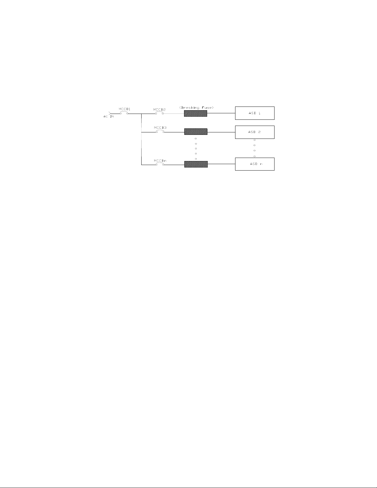
Not all ASDs are equipped with internal primary power input fuses (HP dependent). When connecting
Figure 1. Typical Circuit Breaker Configuration.
CAUTION
Buy: www.ValinOnline.com | Phone 844-385-3099 | Email: CustomerService@valin.com
two or more drives that have no internal fuse to the same power line as shown in Figure 1, it will be
necessary to select a circuit-breaking configuration that wil
1, only MCCB2 trips — not MCCB1. If it is not feasible to use this configuration, insert a fuse between
MCCB2 and ASD 1.
Mounting the ASD
l ensure that if a short circuit occurs in ASD
— The following thermal specifications apply to the 230- and 460-volt ASDs ONLY —
Install the unit securely in a well-ventilated area that is out of direct sunlight.
The process of converting AC to DC and then back to AC produces heat. During normal ASD
operation, up to 5% of the input ener gy to th e ASD may b e dissipated as heat. I f inst alling the ASD in a
cabinet, ensure that there is adequate ventilation.
DO NOT op
The ambient operating temperature rating of the Q9 Plus ASD is 14° to 104° F (-10° to 40° C).
When installing multiple ASDs horizontally, Toshiba recommends at least 5 cm of space between
adjacent units. However, horizontally mounted ASDs may be installed side-by-side with no space in
between the adjacent units if the top cover is removed from each ASD.
For 150 HP ASDs and above, a minimum of 50 cm of space is requ ired abo ve and belo w a djacent units
d any obstruction. This space is the recommended minimum space requirement for the ASD and
an
ensures that adequate ventilation is provided for each unit. More space will provide a better
environment for cooling (see the section titled Part Numbering Convention and Enclosure Dimensions
on pg. 257 for additional information on mounting space requirements).
Note: En
erate the ASD with the enclosure door open.
sure that the ventilation openings are not obstructed.
14 Q9 Plus ASD Insta ll ation and Operatio n Manual
Connecting the ASD
DANGER
DANGER
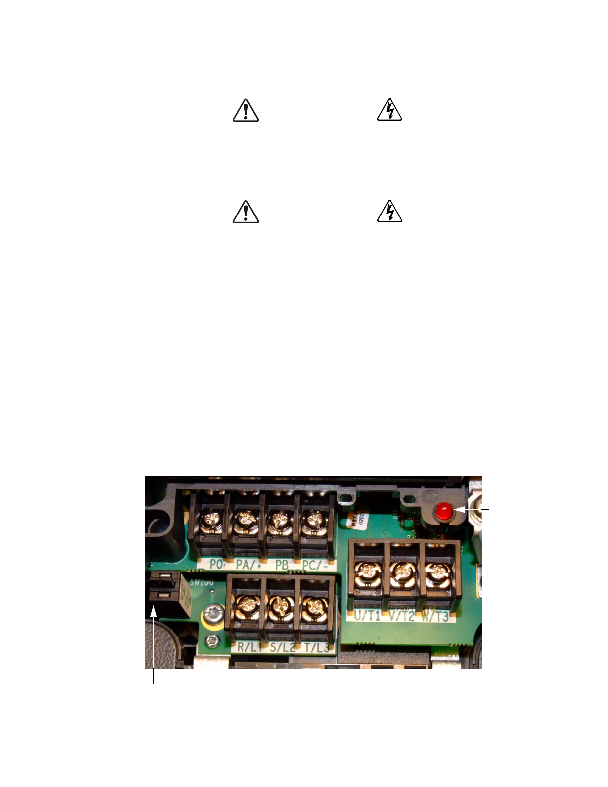
Grounding Capacitor Switch — Pull for Small capacitance/push for Large cap acitance.
Note: PO-to-PA/+ shorting bar removed to show reference designators.
Charge
Indicator
LED
Buy: www.ValinOnline.com | Phone 844-385-3099 | Email: CustomerService@valin.com
Refer to the section titled Installation Precautions on pg. 4 and the section titled Lead Length
Specificati ons on pg. 19 before connecting the ASD and the motor to electrical power.
Power Connections
Contact With 3-Phase Input/Output Terminals May Cause
Electrical Shock Resulting In Injury Or Loss Of Life.
See Figure 20 on pg. 25 for a system I/O connectivity schematic.
An inductor (DCL) may be connected across the PO and PA/+ terminals to provide additional filtering.
When not used, a jumper must be connected across these terminals (see Figure 20 on pg. 25).
PA/+ and PB are used for the DBR connection. The DBR function is NOT used on the Q9 Plus ASD.
PC/- is the negative terminal of the DC bus.
R/L1, S/L2, an
U/T1, V/T2, and W/T3 are the output terminals of the ASD that connect to the motor.
The location of the Charge Indicator LED for the smaller typeform ASD is provided in Figure 2. The
Charge Indicator LED is located on the front door of the enclosure of the larger ASDs.
Figure 2. Typical Q9 Plus ASD input/output terminals and the Grounding Capacitor Switch.
d T/L3 are the 3-phase input supply terminals for the ASD.
Q9 Plus ASD Installation and Operation Manual 15
Power Connection Requirements
Buy: www.ValinOnline.com | Phone 844-385-3099 | Email: CustomerService@valin.com
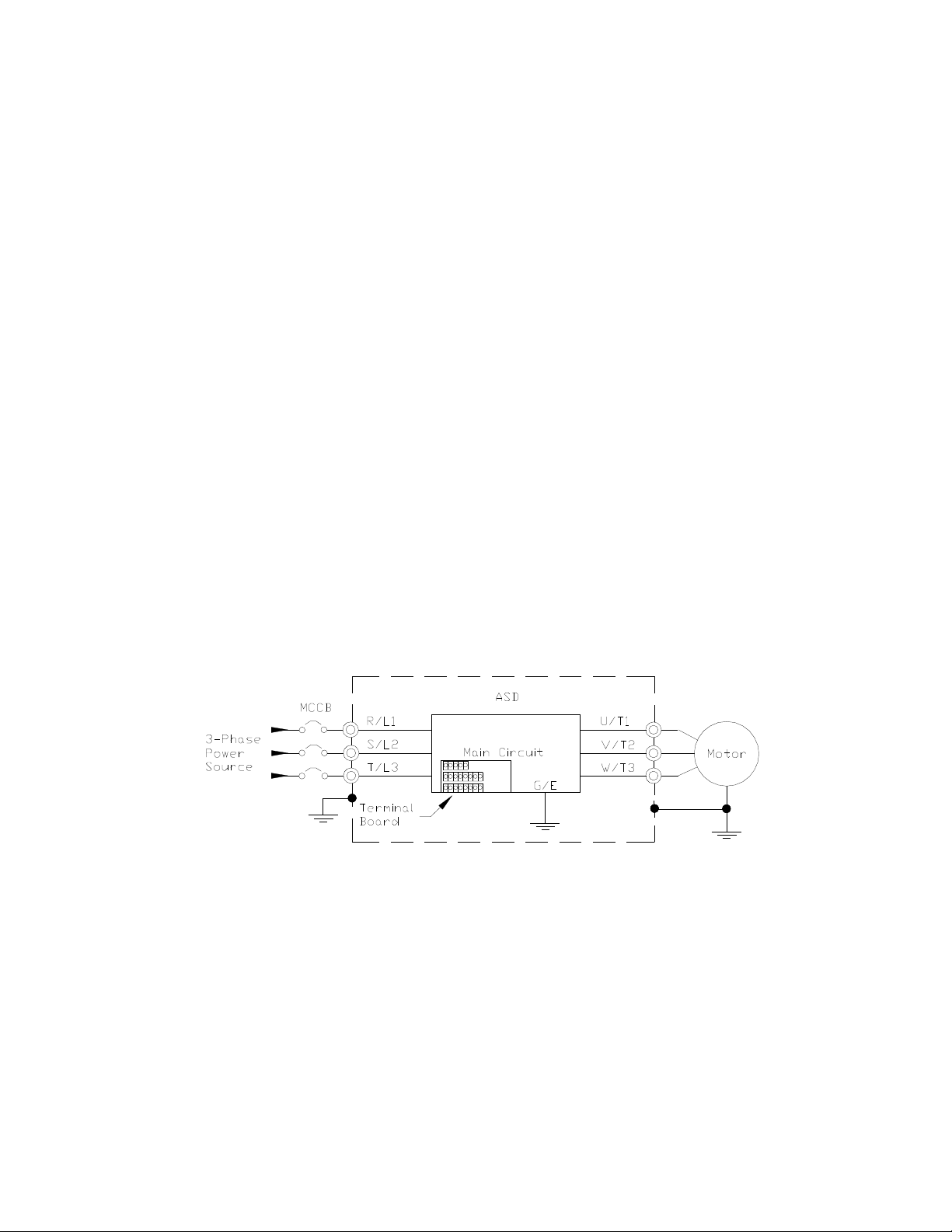
Connect the 3-phase input power to the input terminals of the ASD at R/L1, S/L2, and T/L3
(see Figure 3 for the typical electrical connection scheme). Connec t the outp ut of t he ASD to the mot or
from the ASD terminals U/T1, V/T2, and W/T3. The input and output conductors and terminal lugs
used shall be in accordance with the requirements listed in the section titled Vo ltage/ Current
Specificati ons on pg. 264.
If multiple conductors are used in parallel for the inp
separate conduits, each parallel set shall have its own conduit and not share its conduit with other
parallel sets (i.e., place U1, V1, and W1 in one condu it and U2, V2, and W2 in another — refer to NEC
Article 300.20 and Article 310.4). National and local electrical codes should be referenced if three or
more power conductors are run in the same conduit (refer to NEC Article 310 adjustment factors).
Note: N
Install a molded case circuit breaker (MCCB) or fuse between the 3-phase power source and the ASD in
accordance with the fault current setting of the ASD and NEC Article 430.
The ASD is designed and tested to comply with UL Standard 508C. Modifications to the ASD system
or failure to comply with the short circuit protection requirements outlined in this manual may
disqualify the UL ratin g. See Table 27 on pg. 268 for typeform-specific short circuit protection
recommendations.
As a minimum, the installation of the ASD shall conform to NE
Safety and Health Administration requirements, and to any other local and regional industry codes
and standards.
Note: In
Figure 3. Q9 Plus ASD/Motor Typical Connection Diagram.
ational and local codes should be referenced when running more than three
conductors in the same conduit.
the event that the motor rotates in the wrong direction when powered up, reverse
any two of the three ASD output power leads connected to the motor.
ut or output power and it is necessary to use
C Article 110, the Occupational
16 Q9 Plus ASD Insta ll ation and Operatio n Manual

System Grounding
Buy: www.ValinOnline.com | Phone 844-385-3099 | Email: CustomerService@valin.com
Proper grounding helps to prevent electrical shock and to reduce electrical noise. The Q9 Plus ASD is
designed to be grounded in accordance with Article 250 of the NEC or Section 10/Part One of the
Canadian Electrical Code (CEC).
The grounding conductor shall be sized in accordance with A
Table 6 of the CEC.
—The Metal Of Conduit Is Not An Acceptable Ground—
The input, output, and control lines of the system shall be run in separate metal conduits and each shall
have its own ground conductor.
ASDs produce high-frequency noise — steps must be taken during installation to avoid the negative
ef
fects of noise. Listed below are some examples of measures that will help to combat noise problems.
• DO NO
other, and do not bind them together.
• DO NO
or in parallel with each other, and DO NOT bind them together.
• Use shielded wires or twisted wires for the control circuits.
• Ensure that the grounding terminals (G/E) of the ASD are s
• Connect a surge suppressor to every electromagnetic contactor and every relay installed near the
ASD.
T install the input power and output power wires in the same duct or in parallel with each
T install the input/output power wires and the wires of the control circuit in the same duct
rticle 250-122 of the NEC or Part One-
ecurely connected to ground.
• Install noise filters as required.
Grounding Capacitor
The Grounding Capacitor plays a role in minimizing the effects of leakage current through the ASD
system and through ground paths to other systems. Leakage current may cause the improper operation
of earth-leakage current breakers, leakage-current relays, ground relays, fire alarms, and other sensors
— and it may cause superimposed noise on CRT screens.
The Grounding Capacitor Switch allows the user to quickly change the v
capacitance of the 3-phase input circuit. See figures 4, 5, 6, and 7 on pg. 18 for an electrical depiction of
the leakage-reduction functionality and the methods us
used is typeform-specific.
If using a 460-volt ASD that is in the range of 5.0 HP to 25 HP, and the U/T
connections to the motor are 100 meters or more in length, the ASD Carrier Frequency must be set to
4 kHz or less when activating or deactivating the Grounding Capacitor Switch. ASD overheating may
occur if the Carrier F
Capacitor Switch.
See pg. 5 for more information on the Grounding Capacitor Switch and pg. 15 for the location.
Q9 Plus ASD Installation and Operation Manual 17
requency is set above 4 kHz when activating or deactivating the Grounding
ed to change the capacitance value. The method
alue of the leakage-reduction
1, V/T2, and W/T3
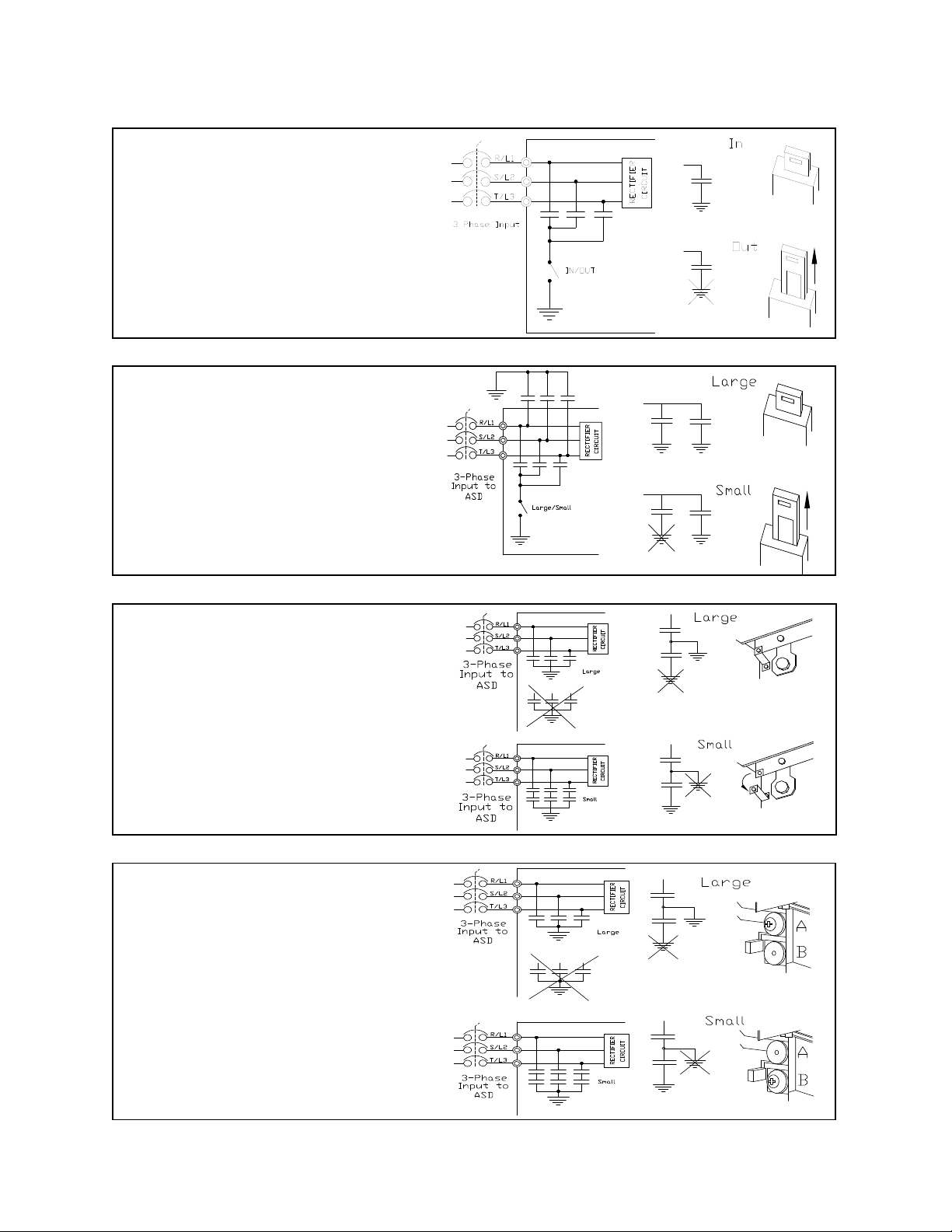
Figure 4. The Grounding Capacitor
Switch is used on typeforms — 200-volt
0.5 HP to 10 HP and the 25 and 30 HP/
460-volt 1.0 HP to 250 HP.
The value may be set to Maximum
(default setting) or to Zero by pushing or
pulling the switch actuator, respectively.
Figure 5. The Grounding Capacitor
Switch is used on type forms — 200-volt
15 HP to 20 HP and the 40 HP to 60 HP/
460-volt 30 HP to 100 HP.
The value may be set to Large (default
setting) or Small by pushing or pulling
the switch actuator, respectively.
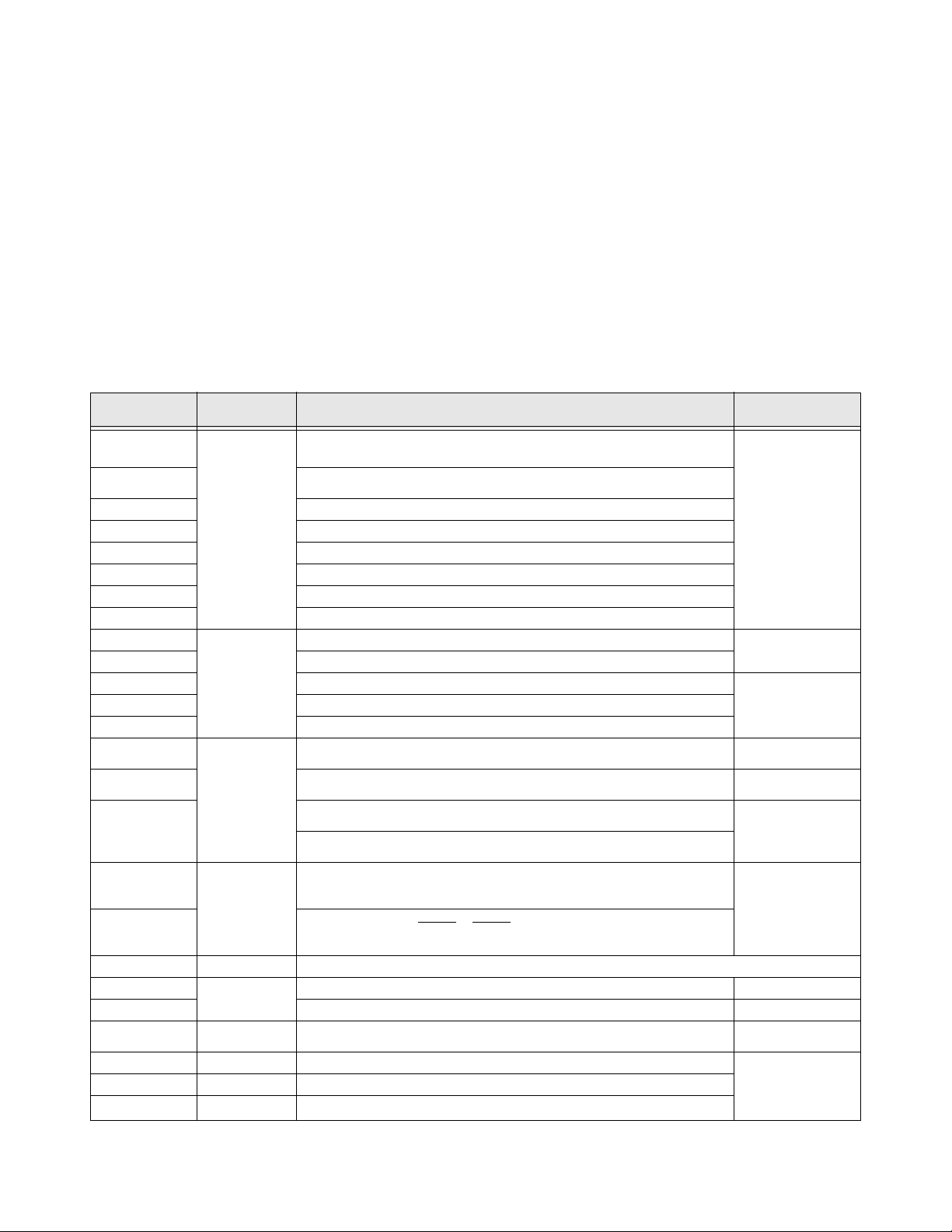
Figure 6. The Grounding Capacitor Bar
is used on typeforms — 200-volt 75 HP
and the 100 HP/460-volt 125 HP and the
150 HP. The value may be set to Large
or Small (default setting) by connecting
or disconnecting the switching bar,
respectively.
Figure 7. The Grounding Capacitor
Screw is used on typeforms — 460-volt
175 HP and above.
The value may be set to Large or Small
(default setting) by placing the screw in
the A position or by placing the screw in
the B position, respectively.
Buy: www.ValinOnline.com | Phone 844-385-3099 | Email: CustomerService@valin.com
18 Q9 Plus ASD Insta ll ation and Operatio n Manual

Lead Length Specifications
Buy: www.ValinOnline.com | Phone 844-385-3099 | Email: CustomerService@valin.com
Adhere to the NEC and any local codes during the installation of ASD/motor systems. Excessive lead
lengths may adversely effect the performance of the motor. Special cables are not required. Table 1 lists
the suggested maximum lead lengths for the listed motor voltages. Lead lengths from the ASD to the
motor in excess of those listed in Table 1 may require filters to be added to the output of the ASD.
Table 1. Lead Length Recommendations.
Model
230-Volt All 1000 feet 450 feet
460-Volt
Note: Contact the TIC Customer Support Cen ter for appli cation ass istance when us ing lead
PWM Carrier
Frequency
< 5 kHz 600 feet 200 feet
5 kHz 300 feet 100 feet
lengths in excess of those listed.
NEMA MG1 Part 31
Compliant Motors
NEMA MG1 Part 30
Compliant Motors
Exceeding the peak voltage rating or the allowable thermal rise time of the motor
insulation will reduce the life expectancy of the motor.
When operating in the Vector Control mode the carrier frequency should be set to
2.2 kHz or above.
Q9 Plus ASD Installation and Operation Manual 19
I/O and Control
Buy: www.ValinOnline.com | Phone 844-385-3099 | Email: CustomerService@valin.com
The ASD can be controlled by s everal input types and combinations thereof, as well as operate within a
wide range of output frequency and vo ltage lev els. This s ection disc usses t he ASD control met hods and
supported I/O functions.
erminal Board supports discrete and analog I/O functions and is shown in Figure 9 on pg. 23.
The T
Table 2 lists the names, descriptions, and default settings (of programmable terminals) of the input and
output terminals of the Terminal Board.
Note: To use the input lines of the Terminal Board to provide Run commands, the
Command Mode setting must be set to Terminal Block .
Figure 20 on pg. 25 shows the typical connection diagram for the Q9 Pl
us ASD system.
Table 2. Terminal Board Terminal Names and Functions.
Terminal Name Input/Output
ST
RES
F Forward — Multifunctional progra mmable discrete input.
R Reverse — Multifunctional program m abl e disc ret e input.
S1 Fire Speed — Multifunctional programmable discrete input.
S2 Preset Speed 2 — Multifunctional programmabl e di screte input.
S3 Damper Feedback — Multifunctional programmable discrete input.
S4 Emergency Off — Multifunctional programmable discrete input.
O1A/B (OUT1)
O2A/B (OUT2) Reach Frequency — Multifunctional programmabl e disc ret e ou tput.
FLA Fault relay (N.O.).
FLC Fault relay (Common).
RR
RX
V/I
(Select V or I via
301)
SW
AM
FM
+SU DC Input Externally-supplie d 24 VD C backup control power (1.1 A m ax.). An alternative to the EOI Bat te ry Backup.
P24
PP 1 0.0 VDC (10 mA max.) voltage source for the external potentiometer. Figure 15 on pg. 24.
FP Pulsed Output
IICC — Return for the V/I input term inal. DO NOT
CCA — Return for the RR, RX, P2
CC — Return for the AM, FM, +SU, and the discrete input terminal.
Discrete Input
Connect to CC to
tivate (Sin k
ac
mode).
Switched Output
Analog Input
Analog Output
DC Output
Standby —
normal ASD operation.
Reset
Faulted — ignored when not Faulted.
Damper Command — Multifunctional programmable discrete output.
Frequency Mode 1 — Mu
input — 0 Hz to Maximum Frequency).
Unassigned —
Unassigned).
Unassigned — V — Multifunctional programmable isolated analog voltage input
(0 to 10 VDC input).
Frequency Mode 2 — I (Default setting) — Multifunctional programmable isolated
analog current input (4 [0] to 20 mADC input — 0 Hz to Maximum Frequency).
Output Current — Voltage outp ut that is proportional to the output current of the
ASD or to the magnitude of the function assigned to this terminal (see Table 11 on pg.
237).
Output Frequency —
frequency of the ASD or to the magnitude of the function assigned to this terminal
(see Table 11 on pg. 237). Select C
24 VDC (200 mA max.) output . Figure 14 on pg. 24.
Output Frequency — Mul
frequency based on the output frequency (see Table 11 on pg. 237).
Function (Default Setting If Programmable)
(see
Terminal Descriptions on pg. 21
Multifunctional programmable discrete input. Activation required for
— Multifunctional pro grammable discrete input. Ac tivation resets ASD when
ltifunctional programmab le ana lo g inp ut . (0.0 t o 10 volt
Multifunctional programmable analog input (-10 to +10 VDC input —
Current or Voltage output that is proportional to the output
urrent or Voltage at F681.
tifunctional programmable output pulse train of a
4, and the PP terminals.
)
Circuit Config.
Figure 10 on pg. 24.
Figure 16 on pg. 24.
Figure 19 on pg. 24.FLB Fault relay (N.C.).
Figure 11 on pg. 24.
Figure 12 on pg. 24.
Figure 13 on pg. 24.
Figure 18 on pg. 24
Figure 17 on pg. 24.
connect to
Earth Gnd
or to each other.
20 Q9 Plus ASD Insta ll ation and Operatio n Manual

Terminal Descriptions
Buy: www.ValinOnline.com | Phone 844-385-3099 | Email: CustomerService@valin.com
Note: The programmable terminal assignments may be accessed and changed from their
default settings as mapped on pg. 46 or via the Direct Access method: Program
Direct Access Applicable Parameter Number. See the section titled Program
Mode Menu Nav igation on pg. 46 for the applicable Direct Access parameter
numbers.
Note: For further informat i on on te rmi na l assignments and default setting changes, see the
sections titled Default Setting Changes on pg. 35 and Input Terminals on pg. 50.
Note: See the section titled Cable/Terminal Specifications on pg. 266 for the Q9 Plus ASD
conductor and terminal electrical specifications.
ST — The default setting for this terminal is the Standby mode controller. As the default setting, this
terminal must be activated for normal sy stem operation. The ST terminal is activated by connecting CC
to this terminal (Sink mode). When deactivated, OFF is displayed on the Frequency Command
screen. This input terminal may be programmed to any of the functions listed in Table 10 on pg. 234
(see F113).
RES — The default setting for this terminal is Reset. The RES terminal is activated by con necting CC
to this terminal (Sink mode). A momentary connection to CC resets the ASD and any fault indications
from the display. Reset is effective when faulted only. This input terminal may be programmed to any
of the functions listed in Table 10 on pg. 234 (see F114).
F — The default setting for this terminal is Forward run command. The F terminal is activated by
connecting CC to this terminal (Sink mode). This input terminal may be programmed to any of the
functions listed in Table 10 on pg. 234 (see F111).
R — The default setting for this terminal is Reverse run command. The R terminal is activated by
connecting CC to this terminal (Sink mode). This input terminal may be programmed to any of the
functions listed in Table 10 on pg. 234 (see F112).
S1 — The default setting for this terminal is Fire Speed. The func tion of thi s input as Fire Speed is to
run the motor at the Preset Speed 1 setting upon activation. This terminal may be activated by
connecting CC to this terminal (Sink mode) and may be initiated by a fire alarm signal or fire/smoke
sensing device. This input terminal may be programmed to any of the functions listed in Table 10 on
pg. 234 (see F115).
S2 — The default setting for this terminal is Preset Speed 2. The function of this input as
Preset Speed 2 is to run the motor at the Preset Speed 2 setting upon activation. The terminal may be
activated by connecting CC to this terminal (Sink mode). This input terminal may be programmed to
any of the functions listed in Table 10 on pg. 234 (see F116).
S3 — The default setting for this terminal is Damper Feedback. The function of this input as Damper
Feedback is to complete the requirements for normal system operation as described in Table 10 on
pg. 234. The S3 terminal is activated by connecting CC to this terminal (Sink mode). This input
terminal may be programmed to any of the functions listed in Table 10 on pg. 234 (see F117).
S4 — The default setting for this terminal is Emergency Off (Normally Closed). The Emergency Off
terminal is activated by opening the connection to CC (Sin k mode). The function of this input as
Emergency Off is to remove power from the outp ut of the ASD and may apply a supplement al braking
system using the method selected at the Emergency Off Mode selection parameter (see F603). This
input terminal may be programmed to any of the functions listed in Table 10 on pg. 234 (see F118).
RR — The defaul t function assigned to this terminal is the Frequency Mode 1 setting. The RR
terminal accepts a 0 – 10 VDC inp ut si gnal that i s us ed t o cont r ol the fun ction ass igned to this term inal.
This input terminal may be programmed to control the speed or torque of the motor via an amplitude
setting or regulate by setting a limit. The gain and bias of this terminal may be adjusted for application-
Q9 Plus ASD Installation and Operation Manual 21
 Loading...