

Toshiba HVK-6M40A, VK-6P32A, HVK-6P40A, VK-8M40A, VK-8P40A Installation Operation & Maintenance
...
lvlav.
31, 2012 9:lSAlVl
TOSHIBA
No
1530
P,
2
Document; GF0776{'I-B
INSTRUGTION$
IilSTALLATION
.
OPEFATION
.
MAINTENANCE
Type
VK
&
HVK
Series
Vacuum
Circuit
Breakers 5-15kV
APPLICABLE TYPE FORMS
(1200A) (20004)
(30004)
VK.6M32A VK.6P32A
I.IVK.6M32A
HVK-6P32A
VK.6M4OA VK.BP4OA
HVK-6M4OA HVK'6P4OA
VK"8M4OA
VK-8P4OA VK-8O40
HVK-8M4OA HVK-8P4OA
,VK.1OM25A2
VK-1OF25A2
HVK-lOM25A2
HVK-I0P26A2
VK-10M40A VK-10P40A VK-10040
HVK-1OM4OA HVK.IOP4OA
vK-6M50
vK-6P50 VK-6050
vK-10M50 VK-10P50 VK-10()50
NOTES:
t) The
designation of
H
before
vK
(i€.
HVKI
dsnot€s that the circuit braaker unit
was assembled
in the USA using domestic
and
foreigri
components.
All
'
relErgnces to modal numbere in thie manual will
be by the numbets following
the VK- and
HVK-.
2l Thi! manuel waB writtan
lor tha Toshiba typ€ form circuit
brsakers listed on
thi$
page
used in coniunction
with Toshiba
cells.
For
circuit
brsek6rs
utilized in
the convereion
of
othsr
equipment, a supplemental
i struction manu8l Should
be obEain6d
from lhe conversion manufacturer.
lssued 2/95.
Supemedee GF077401-A Deted 12194.
N4av.
31 2012
9: l5AlVl
t0, )tu
r,
1
INTRODUCTION
Page i
READ THIS MANUAL carefully
for imponant information about
safety, handling,
installation,
operation,
maintenrnce, and
parts
replacements for
spring-operation-type.
VK
and
HVK
series
vacuum
circuit breake6.
This manual
and all accompanying
drawhg$ should
b6 consid€r€d a
pgrmanent paft
of the equlpmgnt.
They should
be
readily
available
for /eview
and
reference
at all timos.
DIMENSIONS
shown in th€ manual are
metric and/or their 1,.S. equivalgnt.
INOUIRIES
should be addressed to;
Field
$ervice
Department
Toshiba lnternational Corporation
13.l31
West Littls York Road
Houston, Texas 77041
USA
Telephone:
1713't
466"0277
(800)
231-1412
(800)
527-12O4
(Cenada)
Fax:
|'7131
466"8773
ll[ffiFiliilC-l
uaa only Torhtba-authodzad
rBptacamont
padr.
nWiF-MiEl
tiris
equipment
is
de3igned and buitt
in
accordance
with
opptioable
sttetl
etandqrds
in 6l{sct on ttle date of manutactu.c. Unautho.hed
modElcadonr wlll
vold wattalty
and cEn ra:uh ln rwera lnJury, daath and
propsrty
dnmag6, Do not
mak6 nny moditicadons to
thi8
ecpipmefi without
tho
written
tpproval of
Toshiba.
6
TOSHIBA INTEFNATIONAL
CORPORATION,
1 995
t!1ay.31.2012
9:15Att1
No.
1510
P,
4
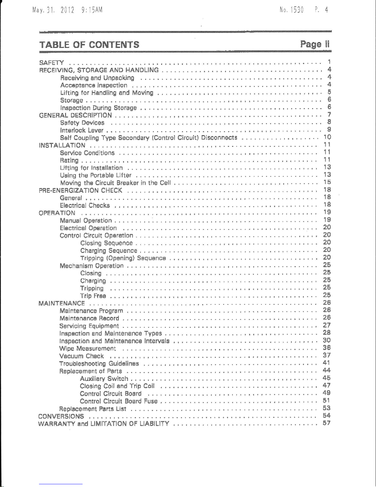
TABLE OF CONTENTS
Page ii
SAFETY
RECEIVING,STORAGEANDHANDLING
,........,,4
Receiving and Unpacking
.........4
Acc€pl6nca lnspection
,...4
Lifting for Handling and Moving
" "
'
5
Stotage,
..'.". t,
lnspection During Stolage
........-
6
GENERALDESCRIPTION
.,..,...7
gafety
Deviceg
........' I
lnterlock Lever , ,
........9
Sell Coupling Type Secondary
(Csntrol
Circuit)
Disconngcts
, .
'
. . 10
INSTALLATION
.,...,
11
Service Conditions
....
..'...... 11
Bating..
...... 11
Lifting tor lnstellation
',.'
13
Using the
Portable Lifter
...'.'.'. 13
Moving the Circuit Breaker in the Cell
.-.....15
PRE-ENERGIZATION
CHECK
..,, 18
General ,
.. ... .
18
Elactrical Checks .
...... t8
oPERATtoN
..,,"..,
19
Manual Operation.....
.'..'.". 19
Electrical Op€ration
.
'
... 20
Controf Ckcult
Oparation
..,.
'., , '
ZO
Closing Sequence.....
..'.20
Charging Sequence
'.......20
Tripping
(Oponing)
Saquanca
....."' 20
Mechanism Operation
....25
Closing .
,.......
25
Charging
.......' 25
Tripping ,
.......
25
Trip Frae
.""...25
MAINTENANCE
...,,, 26
Maintenance Progtam
.... 26
Maintgnanca R€cord
,
.,"
26
Servioing
Equipment
..... ?7
lnspaction
and Maintenance
Type3..
'..'.'.2e
lnspgction and
Mainlenanc€
lnterv8ls
'.
', ',.
30
Wipe Measutement
...
......
'..
36
Vacuum
Chack
,
..-...'
37
Troubleshoothg Guidelines
.,"".41
Replacement of
Parts .
... 44
Auxiliary Switch,
"'.'....45
Closing Coil
and Trip Coil
,
..
....
' ' '
47
Control Citcuit
Board .
..'..4S
Control Circuit Board Fuse
'."'
. . .. .
51
Feplacement
Pans List
...
53
CoNVERS|ONS
.
^....
54
WARBANTYandLIMITATIONOFLIABILITY
..'..'' 57
tvlav
31
2012 9:
l5Al!1
[1o
1530
P5
SAFETY
Page
1
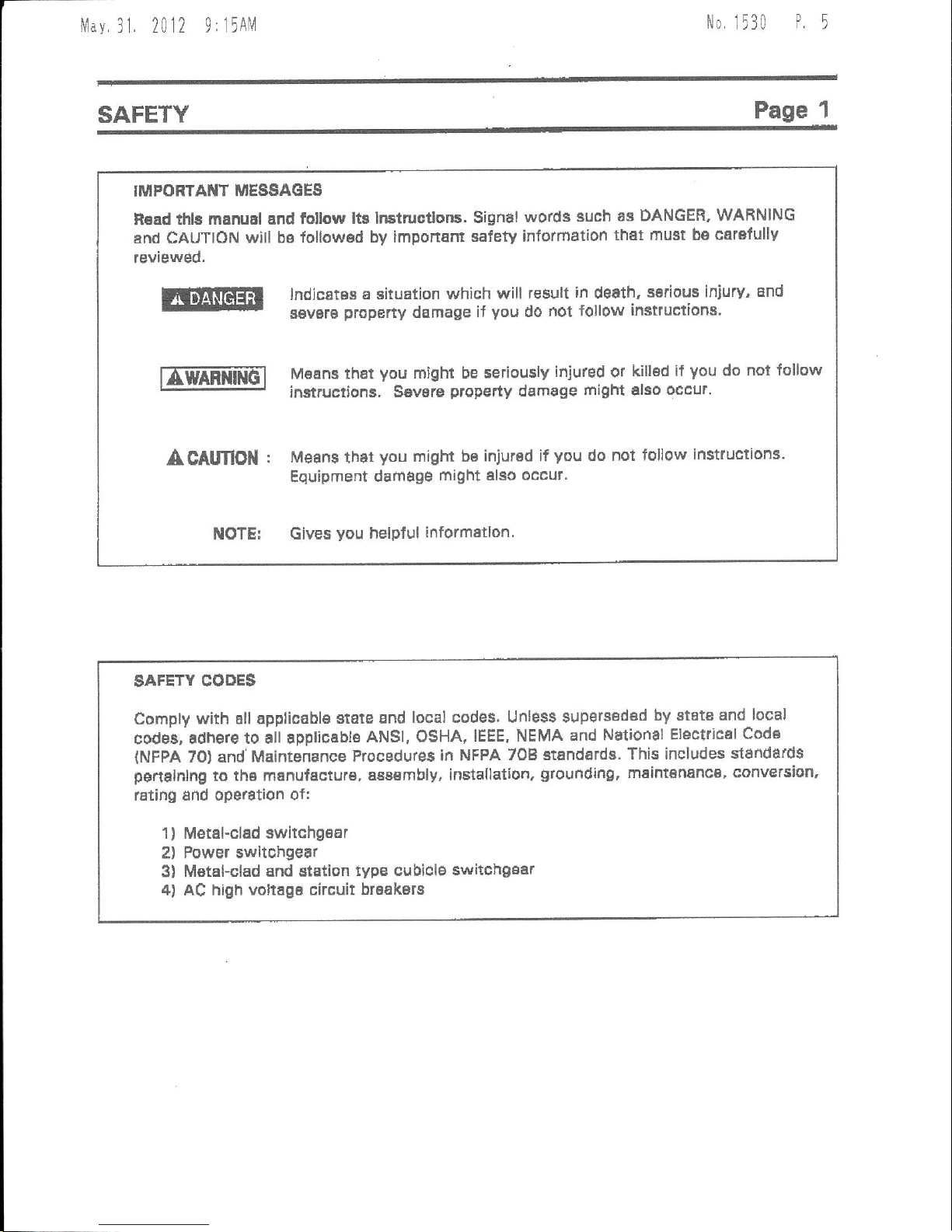
IITJIPO
RTAI{T MESSAG
ES
R€ad
thls manual and follow
lt3 Instruotlons.
Signal
words
such as DANGER'
WAFNING
enrf CAUTION
will bB lollowsd
by imponam
safety information
that
must be catafullv
reviewed.
lndjcates a
situation which
will tesult
in
death,
serious iniury,
and
s€vsrB
propeny
damage
if
you
do
not follow
instructions'
|[mmiilG"l
M66n3 that
you
might be seriouslv
iniured
or
killod
if
you
do
not lollow
r-:'-J
instructions, S€vste
property
demage
tflight
also
occur.
A CAlmOil
: Mean3
that
you
might be
injured if
vou
do
not follow
instructions.
Equipment
damage
might elso occur.
NOTE:
Gives
you
nelpful
informallon'
SAFETY
CODE$
Comply
with all applicable
state and
local codes' Unless $upsrssdad
by etate and
local
codei, adhere
to all appliceble
ANSI, OSHA, IEEE,
NEMA and
National
Eteclrical
Cods
{NFPA
70) and'Maintenance
ProcEdures
in NFPA 708
standarde.
This includes sl6ndards
penalnlng
to
the manufaetu.e,
a88embly, installation,
grounding,
maintananca, conversion,
lating and ope€tion
of:
1
)
Metehclad switchgear
2) Power swltchge8r
3) MetaFclad
snd stEtion
typg cubiclE switchgsar
4) AC hiqh voltagB
circuit braakers
llav.
3I 2012
0,
15AM
No. 1530
P6
Page 2
SAFETY
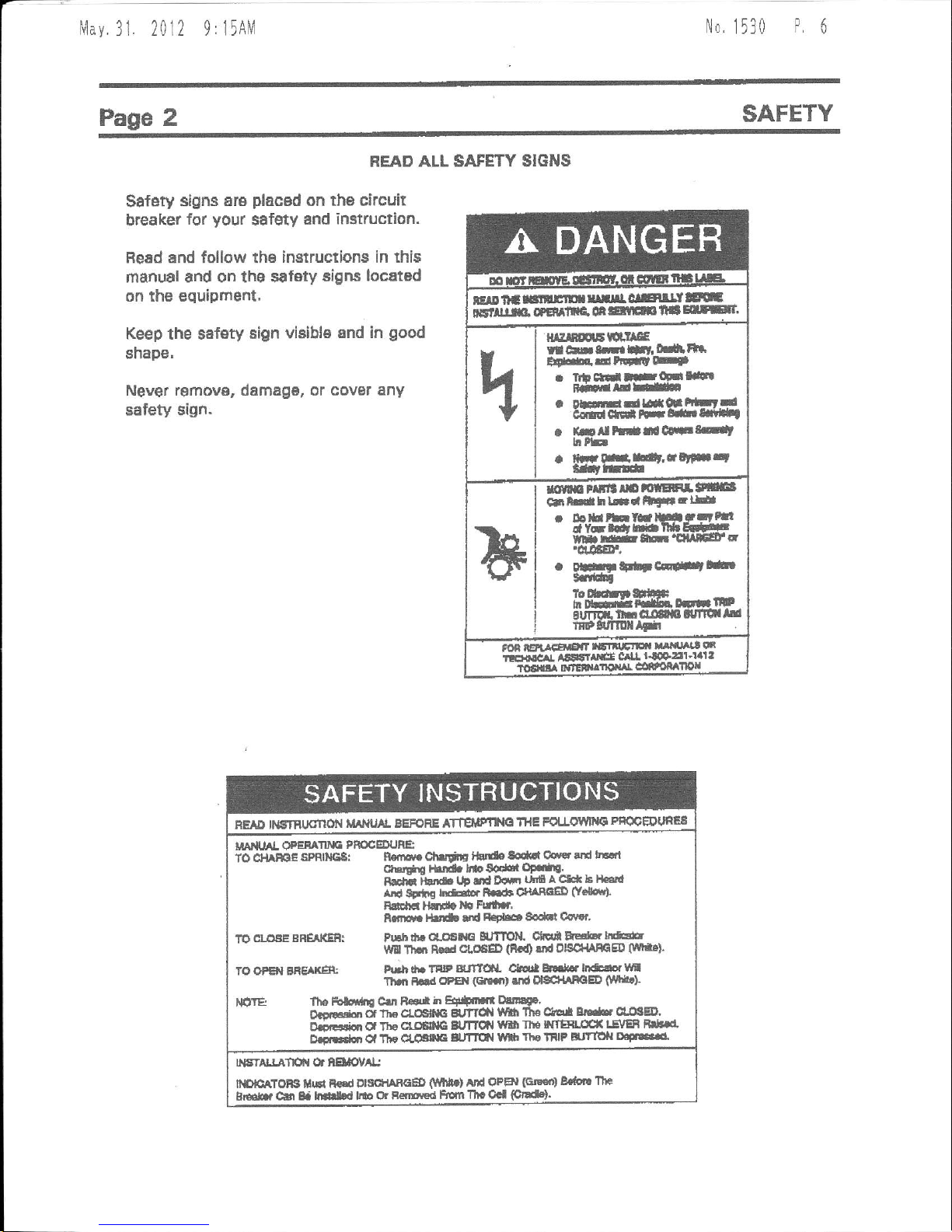
READ ALL SAFETY SIGNS
Safety
slgns are
placed
on ths circuit
breaker
for
your
safety
and imtruction.
BeEd and follow tha
instructions in this
manual
and on tho safety
signs locatod
on rhe equipment.
Keep
the sefsty
sign viaible
and in
good
shape,
Never removg, damag6, or covat
any
safety sign.
ElDltagr|rtnfilrlclElrltr
ictllim.
eemre
orlanrrr
lta
E[Et
H^TNHEH'IE
r ArN.irfit'
m,tla
tFGaHtE
. tt clal tFq-llll
i-HirdE
. DEEdtgqt
trLrd
arqrc(ilt* Hlf,ln*f
a
irll
trdrlecEtd
hrb
. ffi lrrildr,iq
ntt
!.ltffilr
*flm
rrrlt
r[ ffiEF]a
!!
cltlrdhLilriFtLE
. btuhht!5ttrttll
dy-tCrttlUEl*'E
trf
rrE t&r'ClUfiFa
'd.aEr,
.
orF
tFtt cF#tbr
tdfr
FEAD tt€tnrJdflol{
t&lluAl BEFoRE ATTElptlE
THE
FoUOlltttt
pfiQOEltJfiES
uAr{rAl oFEE
s PmcEDt'Ae
To $lA*E
stf,Negl n
.g chlrliE f5t*
toqrl cevst
crd hE
(t1.
ii!
;htd. bro Soqbr
OF..fte.
BtEa
-l}
t& tlF fd
Dcttt
unfl a cH b tLtlll
erd sEtla
rr&or R.le ofiAndD
g.lqr).
Rd€ ldt{e
Fdt r'
ilttHr
l5t rtd
R€tbat 8o.ld
Csnr'
1rO.La!!FSREAIGRT
Fllhdlrat,(!
G eJfllll
Ctqi Es'b.lre
\irf, Tllql
R€rd
ctoeED
(is0
{td OlSCt{AffiED
0rn'}
7o OPB{ BRE
xE t h.lr
A. TflrP
gJftSL
Ch * hdr..li*dor
lr
Thrl h
@sl
(Glifit
rd ol8C+lrhOED
$nr.!
lfiftE
fhe Folci'rn C||t
R€sa
h Ef,+trsr Olttqg.
o.dgidl
*
rlE cLodta
gt
tTct{
lllfi 1'lr€ drEi
Er*. clllg4r'
aj-r!+*n Oa
The
cr.CElcc BUTllll
Yflt llro wTEH.rffi
lE\rEB Br*rr
D.i.doi Cl Tlta
dr6
E
gufltil
!\{l
lltelilP Jtlofi
D'F t'c5'
NsnLLAfn chElaol/^l.j
ITFEATOB t{$i FFd
OtSfi
RaED
(!lt{t}
Atld OpBl
GlE€o)
8.aort
lttc
gr*.
Cfi tf mH
lllo cjr Fentle<t
lErnn Tll. Ocl
(ffi).

N4av.
3I 2012
9: l5AlV
No
1530
P,
1
gAFETY
Page
3
OUALIFIED
OPERATORS
OilLY
only
quslified
persons
are to
lnstall, op€rate
or service
this €qulpmefi
accordjng
to all
applicabls
codes and established
safgty
practic6s.
A
quallfle
d
person
must:
1
)
Getelully
tead th6 entlte
iGtruction
tnanual.
2) Be $killed
in the
installation, construction
or opgration
of the Equipment
and awa/e Ol
the hazards involved.
3l
Be lrainad
and suthorized to $sf€ly
energizB,
de-enetgize,
clear,
ground,
lockout
8nd
tag circuits
ln accordEnce
wilh estSbli$hed
sefsty
practice.
4) Be trained ahd
Suthorized
to
parform
the service,
maiftenancs or
rspair of this
aquipment.
5)
Be
trained
in the
proper
care
and use of
protectiva
equipment
such as
rubber
glove$,
hsrd hat, safety
glassos,
face shield'
flash clothing, etc.
in
accordance
with
astabllshBd
practlces.
6)
Bp
tr9ln6d
in rendering
first aid.
Nlav
31. 2012 9:15AN4
No.
1530
P.
I
Page 4
RECEIVING, HANDLING
AND $TORAGE
RECEIVIIIo AND UIUPACKING
The
clrcuh breqker
unite
are aubjected to
fEctory
production
testlng
prlor
to
being
packed
and shipped.
ACCSPTAilCE IiI$PECNON
Confirm that
the
circuil breake, unit
is
oompleta,
conect as :pecified and undamaged
trom shipment 6nd
handling.
Upon
recelpt
of the
equipmBnt, do the
following:
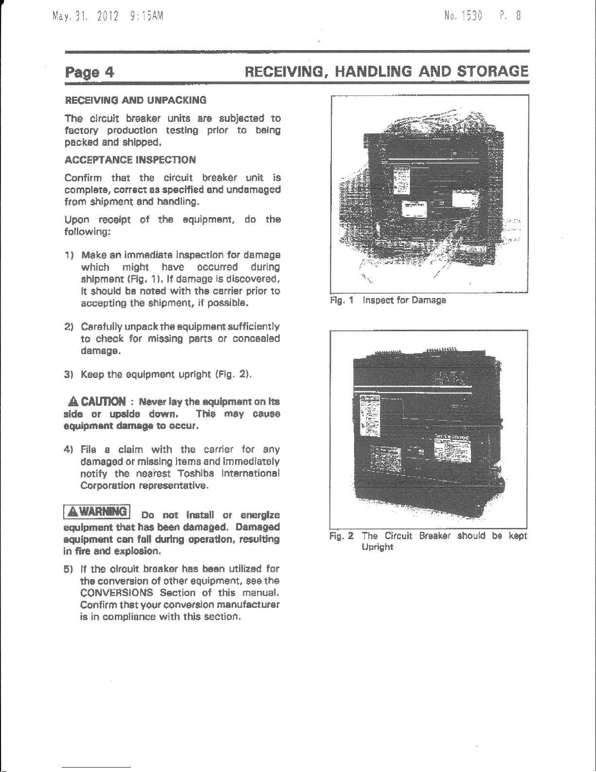
1) Make
an
lmm€diat€ ircpeclion
for damag€
which miotx
have
occurred
durlng
Ehipment
(Fig.
1
).
lf
damage
is
discove.ed,
it
should
be notad with th€ carrier
prior
to
accepting
the
shipment
if
p+asibla.
2)
Carelully
unpack tha aquipmant sufficiently
to cheok
for missing
pens
or concealed
damage-
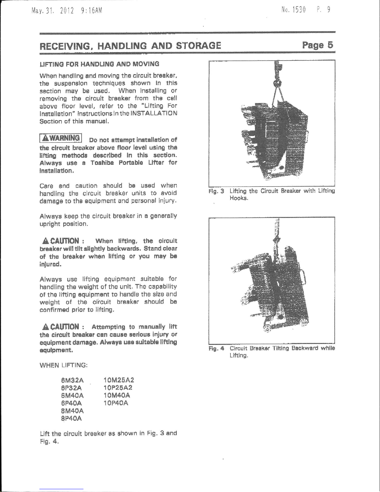
3l Keep the equipmefi
upright
(Flg.
2).
A
CAltflOil
r ltl.vat
hy th6
esripmam on lia
elde or upslde dwn. Tlf$
may
cause
equhmrm
drmrge to occur.
4) File
a
claim with the
csrrier
for
$ny
damaggd
or missing itsms €nd immediately
notily the
neaiest Toshlbe lnternational
Corporation representative.
IZffil
oo nor i6ral or en€rllze
eqrlpmEnt trat
has
bcan *rflagsd.
Drmegod
iquipmilt can fdl drdng operadon, tctultidg
in fire snd
exploEion.
5) lf the cucuit
braikor
haa
baen
utilized
for
rhe conveFion of olher equipmert, see the
CONVERSIONS
S6etion ot this manual.
Cofifirm th€t
yo{lr
conver8ion
msnufecturer
is in compliance with
thi$ section.
Flg. t lnspedl for Damaga
Fi!. Z Thb Circuit Brdsk8r Bhould
Uprighr
kept
llav.31
2012
9:16AM
No
1530
P9
RECEIVING,
HANDLING
AND STORAGE
Page 5
LIFTINd
FOR HANDLING
AND MOVING
When
handllng
and
movlng
the
circuit braskdr,
rhe suspension
technlques shown
ln this
saction
may b6 used. When installing
or
removing
th6 circuit braaker
from the csll
above
floor
level, refer
to the
"Lifting For
I nstaltation"
instructions
id the
I N$TALLATIO
N
Sgction
of thie mpnual,
ffmnlGl Do nor atbmpr instattation
of
the clrouit bteaker
above
floot leyel u3ing the
lifting
m€thod8 d€scdbed
ln thls section.
Alway$ u$e
e Tolhibe
Portsbla Llfter
for
lnstalladon,
Care and
csution
should ba
usad when
handling
the circuit
breaker units
to avoid
damage to tha aquipment
and
personal
injury.
Always
keep the circuit bf€aker
in e
genBrally
upright
position.
ACAUflON
!
when
littlng,
the oircuit
breekar
vvlll tllt rllghtly backwards.
Stand clear
of
the bteake.
whon
lifting or
you
may be
inlured,
Always use
lifting
equipmant
suilable for
handling ths weight of the
unit.
The
capability
of the
llfting equipment to
handle the size and
weight
of the ciicuit
br6aker should
be
confirmed
prior
to lifting,
A
CAlmON
I
Attempting
to
menually lift
the
circull bruakar
csn caure ledous injury
or
equiprro
t damtge.
Alwey: u:a
eultoHe llftlng
equJpmerTt,
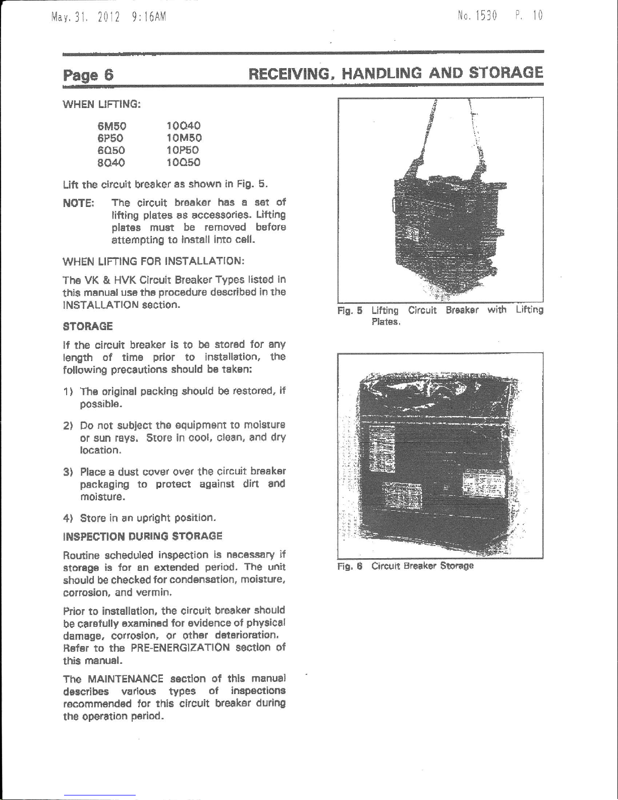
FlE.
3
Lifting
the Cirouit
Hooks.
Breaker
with Lifting
Fig. 4 Circuit
Br6ehsr Tihing Beckward
whils
Lifting.
WHEN
LIFTING:
6M32A
6P32A
6M4OA
6P4OA
8M4OA
8P4OA
10M25A2
10P25A2
10M40A
10P40A
Lift ihe
circuit breaker as
shown
ih Fig. 3 end
Fig. 4.
li1av
31 2012 9:
l6AlVl
Itlo,
1 13 0
P
t0
WHEN LIFTING:
6M50
6P50
6050
8040
Lift the circuil
breaker
as shown in
Fig. 5.
The
circuit
braak€r
ha,B a eet of
lifting
plates
as accessories.
Ufting
pletes
must be
removed before
atterfiptlng
to lnstall into c6ll.
WHEN LIFTING FOR
INSTALLATION:
The VK & HVK Gircuit Breaker
Types listed ln
thi$
manual
us€ the
procedure
described
in the
INSTALLATION
section-
STORAGE
lf the
circuit breaker
is
to be
stored
lor any
length of
timB
prior
to installation,
the
following
precautiotar
should
be taken:
The original
packing
should be
restor€d, lf
possibl6.
Do
not
subject
th€
€quipmBnt
to moisturB
or aun
rays. srote in oool,
cl6an, and dry
locetlon.
Place a dust cover over
the circuit
br€ak6r
packaging
to
prot€ct
against dift
and
moisture.
$tote
in an upright
Position.
INSPECTION
OURING STORAGE
Rouine
scheduled
inspection ls nec6s34ry
if
storage
iE lor En extended
period.
The
dlit
should b€ checked
for condensation,
moi$ure,
cottogion,
and vermin,
ftior to instEllation,
the circuit breaker
should
be crrefully
6xamined
lor ovidence of
phy$ical
damage. cotto$ion,
or othsr
doteaioration.
Hof6r
to thc PRE-ENERGIZATION
ssctlon of
this
menual.
The MAINTENANCE
sEction of this
manual
describes
vatious typ$
of
impsc.tiong
recommsndsd
for this
circuit breaksr
durlng
the
operstlon
P€riod.
REGEIVING,
HANDLING
AND
STOHAGE
t
1
10040
10M50
10P50
roo50
NOTE:
Fig. 5
Lifting Circuit
Plat68,
with Lifting
1)
2t
3)
4)
Fig, e
Circuir
Breekef
S$.ag€
lvlav.
31 2012
9: 16AM
No
1530
P.
tl
GENERAL
DESCRIPTION
Page 7
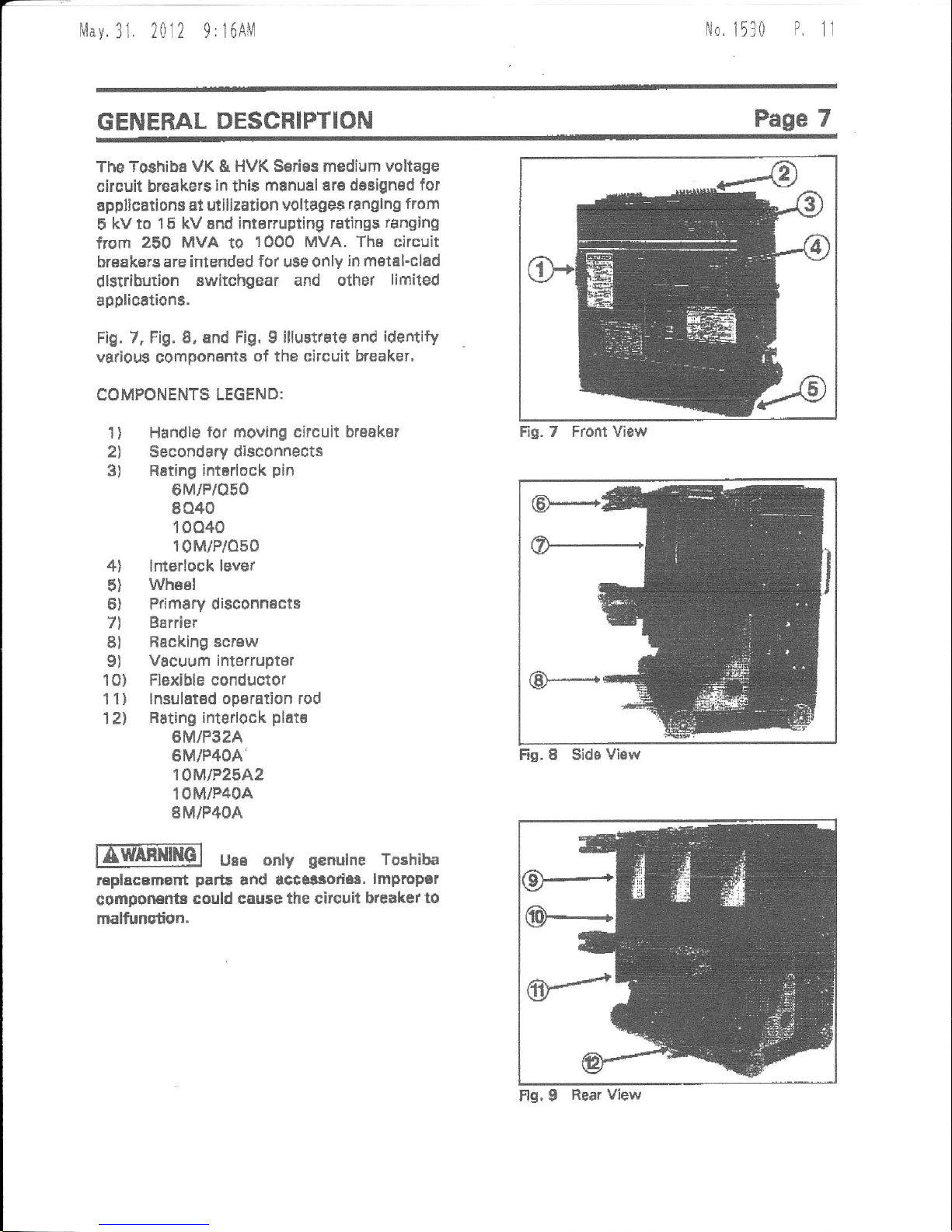
The Toshiba
VK
&
HVK Serias medium voltage
circuit breakers
in
thi6
manuel are dasigned
for
applica offi at utilization
voltages
ranglno from
5
kv to 15 kV and intorrupting ratings
ranging
from
250 MvA
to
1000 MVA. The circuit
breakarg are inlended
for
use only
in metal-clad
dlstriburion
switchgear and other
lifitited
applicttions.
Fig. 7, Fig. 8, and Fig,
g
illust.ate and
identify
various component8
of the circuit b'eaker,
COMPONENTS
LEGEND:
1
)
Handle
lor moving circuit breakar
2l Secondary disconnects
3) Rsting
intBrlock
pin
0M/P/oF0
8040
10040
10M/P/o50
4l lnterlock lever
5)
Whssl
6) Primary disconnscts
7l
Barrier
Bl
Rscking scrsw
9)
Vacuum interrupter
1O)
Flexible conductor
11) lnsulatsd
opsration rod
1Zl
Bating interlock
plat€
6M/P32A
6M/P4OA'
10M|P25A2
10M/P40A
8M/P4OA
UBE only
g€nulne
Toshiba
replacBm€nt
parE
and accatsod68.
lmproP€r
componEl'tr
could cauee the citcuit breaker
to
malfunction.
Fis. 8 Sids
View
Fio.
7 Front Viaw
Fls, I
Rear View
Mav.31
2012 9rl6AM
No,
1530
P.
12
SAFETY
DEI/ICES
Sat61y
inr€rlockg and
guards
sre
provid€d
as
an
iftegr8l
pen
ol th€ €quipment deslgn.
These devices are
provided
for
your
BafBty.
Never Defeat, Modfy or
Bypa*
any Satety
El6vlc53,
lmerloeks. or
operadng mechanfim.
Ttrt world
make
the
enripment
unsati. Flre. erploCon,
gevere
Ir{ury,
death, and
propafi
damage could
occul,
nml
Do not o'€rate th* equipm€nt
unle$s all soverE
and
panelr
sr€ ln
place-
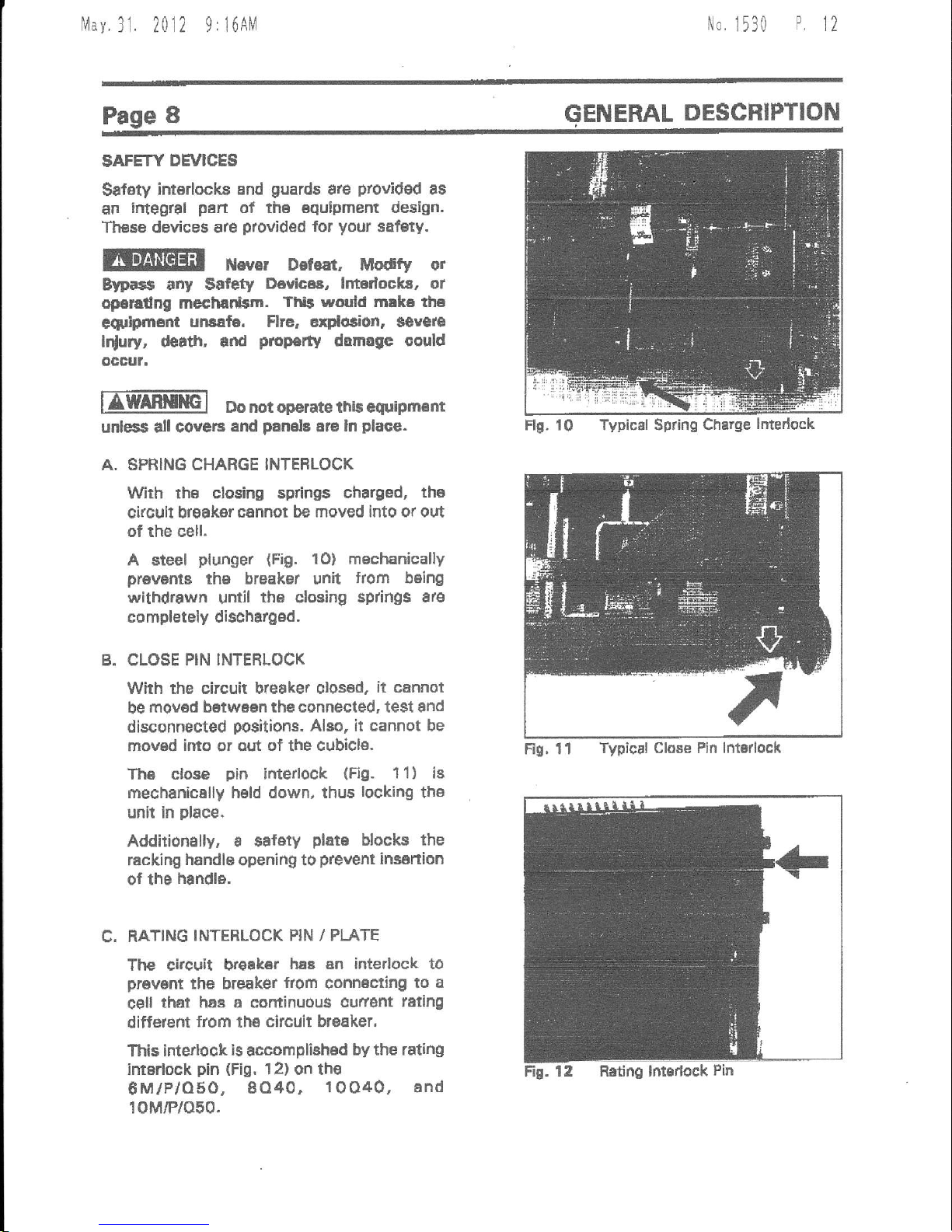
A. SPRING CHARGE INTEFLOCK
With the clesing springs
charged,
tha
circuft break€r
cannot be moved into or out
of the cell.
A steel
plunger
{Fig.
10} mechanically
prawms
th€
breakel unit
from being
withdrawn
until
thB
closing
sp ngs 8re
completely dischargod.
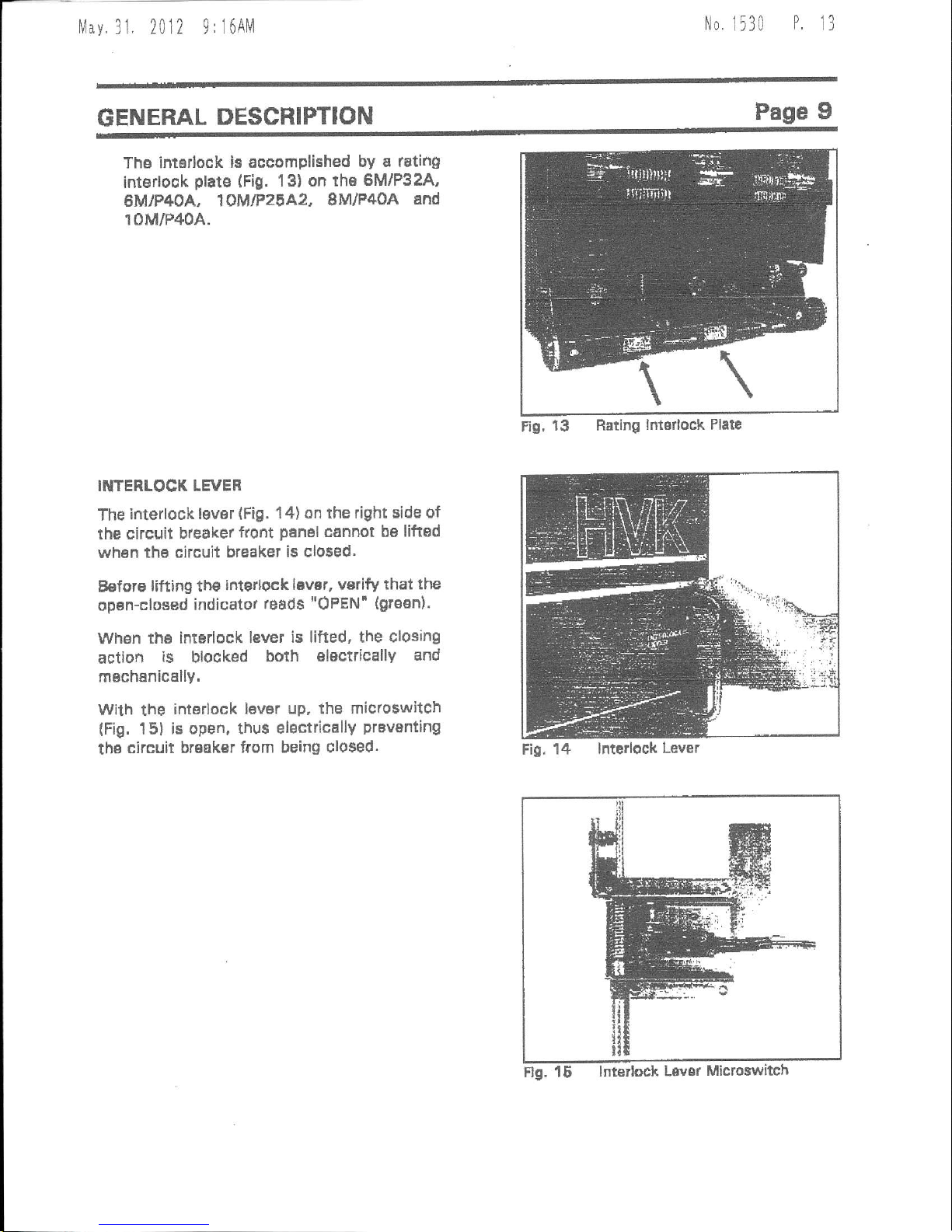
B. CLOSE
PIN INTERLOCK
With the circuit bteaker olosed,
it cannot
be
mov6d betwaen the connected, test and
disconnected
positiorc.
Alao, it cannot be
mov6d
into
or aut of the
cubicl6.
Th6 close
pin
ifiterlock
(Fig.
1 1
)
is
mechanically held down, thus
locking
the
unit in
place.
Addition€lly, a salety
plats
blocks the
racking handle opening to
prevent
insartion
0f
the
handle.
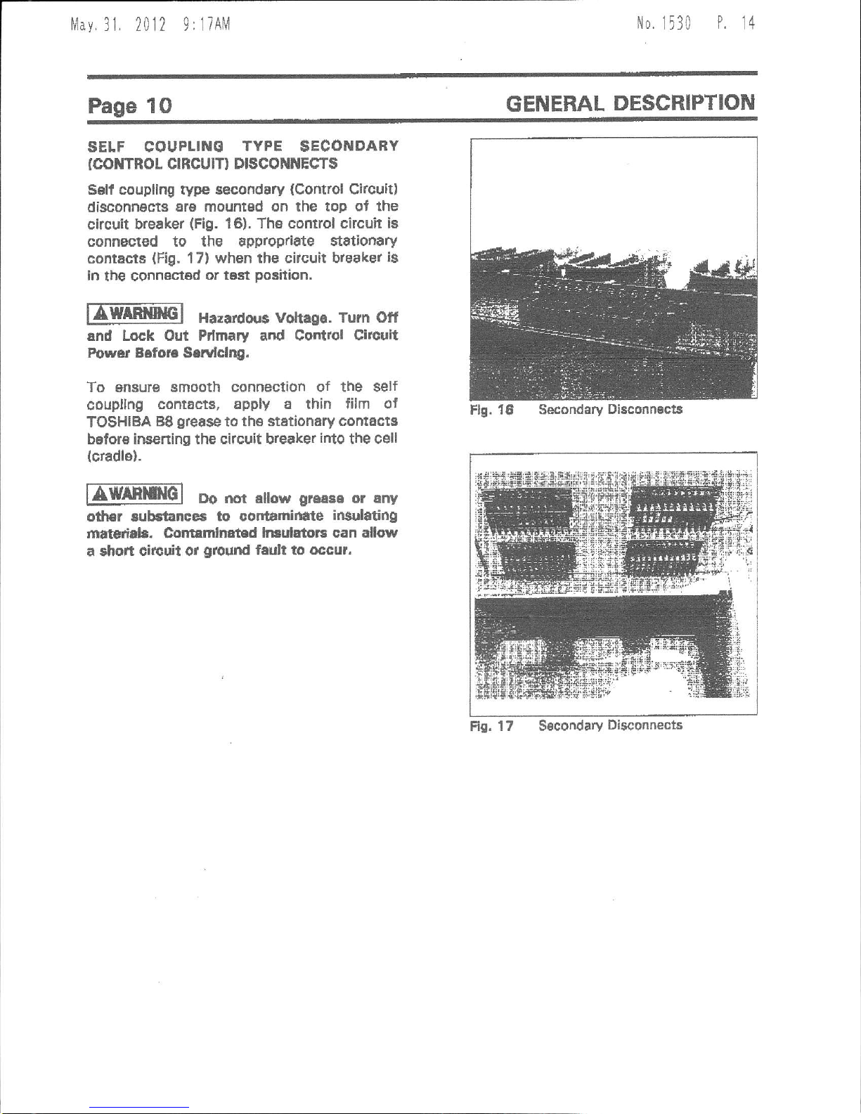
C. RATING
INTERLOCK PIN / PI-ATE
The citcuit H€ak€r
hsB sn interlock to
prevsnt
the breaker
fiom
conn6cting
to a
c€ll
that hae a cominuous
cufierrt
reling
difterent
from
the
circuit br6aker,
This intertock
is
accomplished
by the rating
intarlock
pin
(Fig,
l2) on the
8M/P/O50,
8O40.
1OO40, and
10M/P/O50.
ENERAL
DESCFIPTION
Rs, 11
Typical Close Pin lntorlock
Flg. 10 TypicNl Spring
Charge
lntedock
Mav.31,
2012
9:i6AM
No,
1530
P
t3
GENERAL
DESCRIPTION
Page
9
Ths intddock
ie accomplished
by a rating
interlook
plats
(Fig.
1 3) on the
6MlP32A,
eMlP4OA,
19MtP2gA2,
8M/P40A
and
10M/P40A.
INTENLOCK LEVER
The
interlock
lever
(Fig.
'14)
on the right side
of
the circuit
bleaker
front
panal
cannot be liftad
wh6n
thB circuit breaket
is clo$ed.
Belore
lifting th€
interlock lBvsr, vsrify
that the
opan-closed
indicator
reads
"OPEN'
(grosn).
when
tho interlock lever
is lifted, the
closing
action
is
blocked
boih
electrically
and
rnsch6nically.
wilh
the
interlock
lever up. the micloswitch
(Fig,
151 is
open, thus electricallY
prevsnting
the
circuit brsak€r from
being closed.
Fig,
13 Rating
lntorlock Plate
Fig,
14 lnterlock
Lever
f/av
31. 2012 9:17Ah1
No,
1530
P.
14
Page
1O
GENERAL
DESCRIPTION
SELF COUPLINE
TYPE
$ECONDAEY
(col{TRor
crRcurr) DrscoililEcT$
Sslt coupllng
rype
secondary
(Control
Cl.cult)
disconnects
Er6 mountsd on the top of the
circuit breaker
(Fig.
16).
The comrol circuh ia
connected to the approp/idte $t8tionary
contacts
{Fig.
17} when the citcuit breake.
is
ln
tbe
connestsd
or t6st
position.
fA-l
Hazardorr6 votraga,
Turn otf
and Lock Out Pdmary and Control Circuit
Power B6for€ Sarvlclqg.
To snsur€ smooth connection
of the self
coupllng
contact8, apply a thin film ol
TOSHIBA
B8
grease
to
th€ stationary
cornacts
before insening the
circuit breaker
irto
the cell
(cradle).
nWAf,rcl
Do mt alow
greese
or any
od|3r aubstanccs to cortamid
te
insulating
mNtcriab. Colrtrmlnat
d ln ulatots can allow
a shon
circuit or
ground
fadt to occur.
Fr0.
17
Secondary
Disconnecis
Flg. 16 Secondary
Di8conn€ct8
lvlay.
31, 2012
9:lTAlVl
No
1530
P.
1t
INSTALLATION
Page
11
SERVICE
CONDITTOilS
EWAEtlilG-l
Do nqt ini1pll
rhis
aquipm.m
in areas
where unurual
serviae condition$
erist.
Using thiE €quipm€nt
ln othsr than uaual
aervlce
condffod$ can
relult in squipm€nt
fallura,
Toshibs
VK
&
HVK
$eri€s
Circuit Brsak€rt ara
intended
for
use
in u6ual servioe
conditions as
dellndd
by ANSI. The
temperatule of the air
(arfibient
air temp6raturs)
surrounding
the
Ewitchgear
should be
between the
limits of
-3OoC
l.22oF)
snd +4OoC
(104oF),
The
altitude of the equipffient
instsllation should
nor exceed
3300 ft
{100o
m},
IUOTE;
Temperature,
ehitutle ot othar
conditions outside
of the usual
limitt
may raquire derating
or other special
equiPment.
Contact ToEhiba
lntsrnational CorPoration
for
additional lntormstion.
RATIIVG
Prior
to
ln$tallation:
The
maximum fault curredt
capaoily
ol tho
powsr
sy3t6m
at thB
point
of
installstion
should be
verified. This
valug must not exceed
ths symmetrical
interruptino eapability
ot the
circult
bteaker.
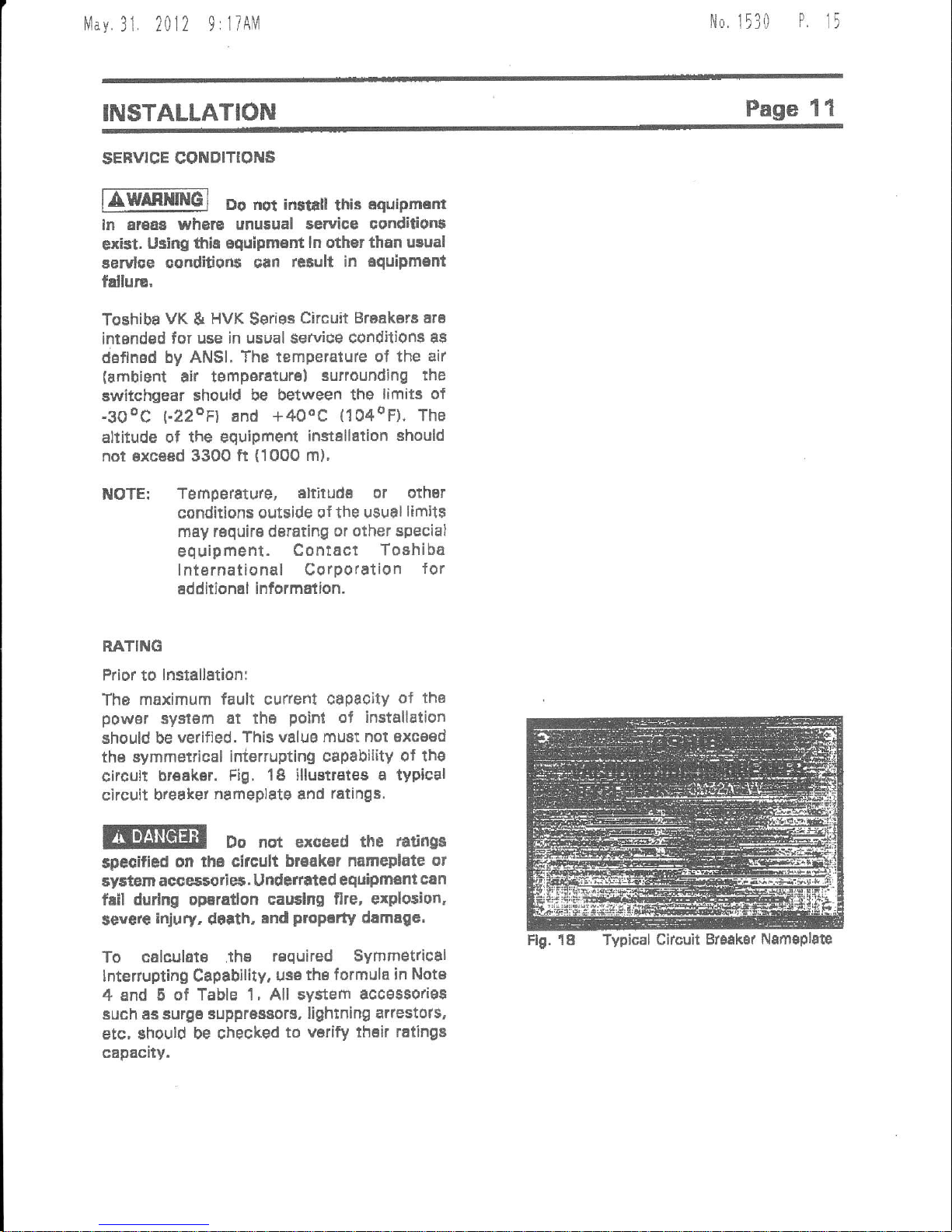
Fig. 18 illuetrEtes
a typical
circuit breaket
nameplatg
and
ratings.
Do not exceed
the
tati
ga
$pecified
on
fi6 circult
braak€r nameplate
ot
aystem acces5orie5.
undefrated
equipment
can
fail
durlng oparallon caudng
flre, erploaion,
sgvgrg
inju
. d6rth,
ind
proP.dy
damagc,
To calculat€ .th€
required Symmetrical
lnterrupti
g
Capability.
usatheformula
in Note
4 and 5
of Table 1, All system
accss9origs
Buch as surge supprasaors,
lightning arlestols,
etc, should
be checked
to
varify thsir ratingi
capacity.
Flg. 18 Typical
Ciacuit Br3aker
Nsmsplac
1,,1av.31.
2012 9:17AM
N0.
1530
P
16
Idofiificdidr
RddVdlr
::;..itH6l
it:iji6flil;&l
i"i;6,1.{iri:
|-., i..i i:lc
.3frNt
ltl.i irE8li.i
"t:i
'.
Er!
r!t5! r
+.r'ri ,
r}'
H
f,..!H
V*{t
0t
!.Yl
tldt
3tln
{xv t
r4ahg
tffi)
r#*
r,iri{
Dty, V
!E
6a.d
Htr-
E
{rYl
t2f
Y*rt
nrrF
t
cat'
ht
\'hrg
tsr
lhr
rl
€oll
{At
ESA
Atrr
*sln
ht}rg
la
lls.
rvt
lrat
t4)'
F4ruy
VB
lvl
AIE2A
6Fil2A
4.16
!t.16
2SO
150
1,76
4.78
't.24
1,21
l9
to
60
m
1200
zxxt
29
za
I
3 2
E.a6
s,gt
3lt
3A
a0 6E
5A
al,tloA {rf
6goa
of
4.lE
!t.t6
s60
950
\7d
d76
t-d
I
O
te
IE
60
@
l roo
zu)
,t1
3
2
2
4.78
1.',1c
4t
4l
41
+1
SB
6E
Etfio
6F60
6(rc
4,16
4.16
ILI
E
Ito
360
361)
47',
+76
4.ta
l-lr
t.t3
t0
19
19
60
60
c0
t tod
20@
3000
tll
4t
4t
I
I
s
,
z
2
lto
a.o
40
43
att
49
49
a0
4S
7t
7t
7e
Ar,lbA
I'IIOA
80,to
tlf
7,4
7.2
300
6('0
500
d.:5
a.r3
a,z5
l.r5
LB
t.lE
36
3t
IE
95
tt
SE
I400
20s
gooo
33
t3
3
a
s
2
2
2
4.6
6,6
6,8
41
4i
a1
41
d6
66
6A
I6MfiA'
tot:lt l 13.4
500
5m
t6
l5
t
-30
tJo
36
t!
gE
s
I uao
zn
16
IE
3
s 7
I t.5
l t,3
,3
23
tt
t3
a7
t7
toM{an
't{tFttoa
roq40
tll'
1C.E
I
s.a
l3.a
750
7A
7
IE
ll
IE
t.ao
1.30
t
-so
a8
36
3t
6
t5
t6
1200
:000
3000
2A
28
2E
3
3
2 11.5
36
t6
86
3g
36
36
5S
EA
6E
roP4oA fil
lmto fl r
l!-6
13.8
1066
100(l
t3
IE
t.0
t-0
3C
36
t5
s
2o0o
3000
B7
37
a 2
1E
15
37
g7
l7
6A
F9
lotFo
totto
iooEo
19.t
13,t
t3,8
t 000
looo
1000
16
t5
l5
!
-lo
l,$
1.30
36
3!
36
s
E6
1206
2l'qt
30m
s7
g7
3
I
3
2
2
i t,5
I 1,5
116
49
.t6
4E
4{
*0
46
't7
77
17
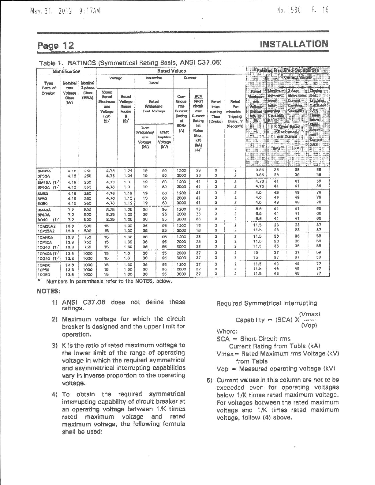
Table
1 . RATINGS
Numbol6
ITIOTES:
Basis,
ANSI C37.06)
r€fer
to the
r)
2l
3)
ANSI C37.OB
does
not
define
thes€
r6tings.
MEximum voltage
for which lhe circuit
breaker
i6 d€signed and th6
upper limit for
operation.
K ic
the
latio
of
rSted maximum
vollage to
th6 lowar limit
of the range ot
opetating
vohage
in which tha roguir€d
symm€trical
and asymmefiical
interrupting cap8bilitiss
vary in inv€rs€
proportion
to the oper€ting
voltSge.
To obtain the
requked symmetrical
interrupting capability
of citcuit breaker
at
an
operEting voltsga betwsBn
1/K times
Irted
m€ximum
voltage
snd
ratad
maximum vohage,
the tollowing formulS
shall be
usBd:
Required Symmetrical
lfierruptlng
(vmex)
Capability=(SCA)X*-*
(vop)
where:
SCA = Short-Circuit
rms
Currant
Rating from
Table
(kAl
Vmax=
Faled
Maximum rms Voltega
{kV}
from Table
Vop
=
Measured
operating
voltage
(kV)
5) Crlrrsnt
veluas in thb column
are not to
be
excEeded even
{or
operatihg
voltages
below
1/K tim6s
rated maximum voltage'
For voltages bstwBsn
the ratad maximum
voltage
8nd
l/K
times
rated maximum
voltage, lollow
{4)
above,
4)
Nlav
31. 2012 9:liAM
No.
1530
P
17
INSTALLATION
Page 13
LIFTING FOF INSTALLATIOil
lJnlika the
lifting
procedures
recommended
in
the
FECEIVING,
STORAGE AND HANDLING
section,
Lifting
for lnstallation
pulposas
raquires a different technique,
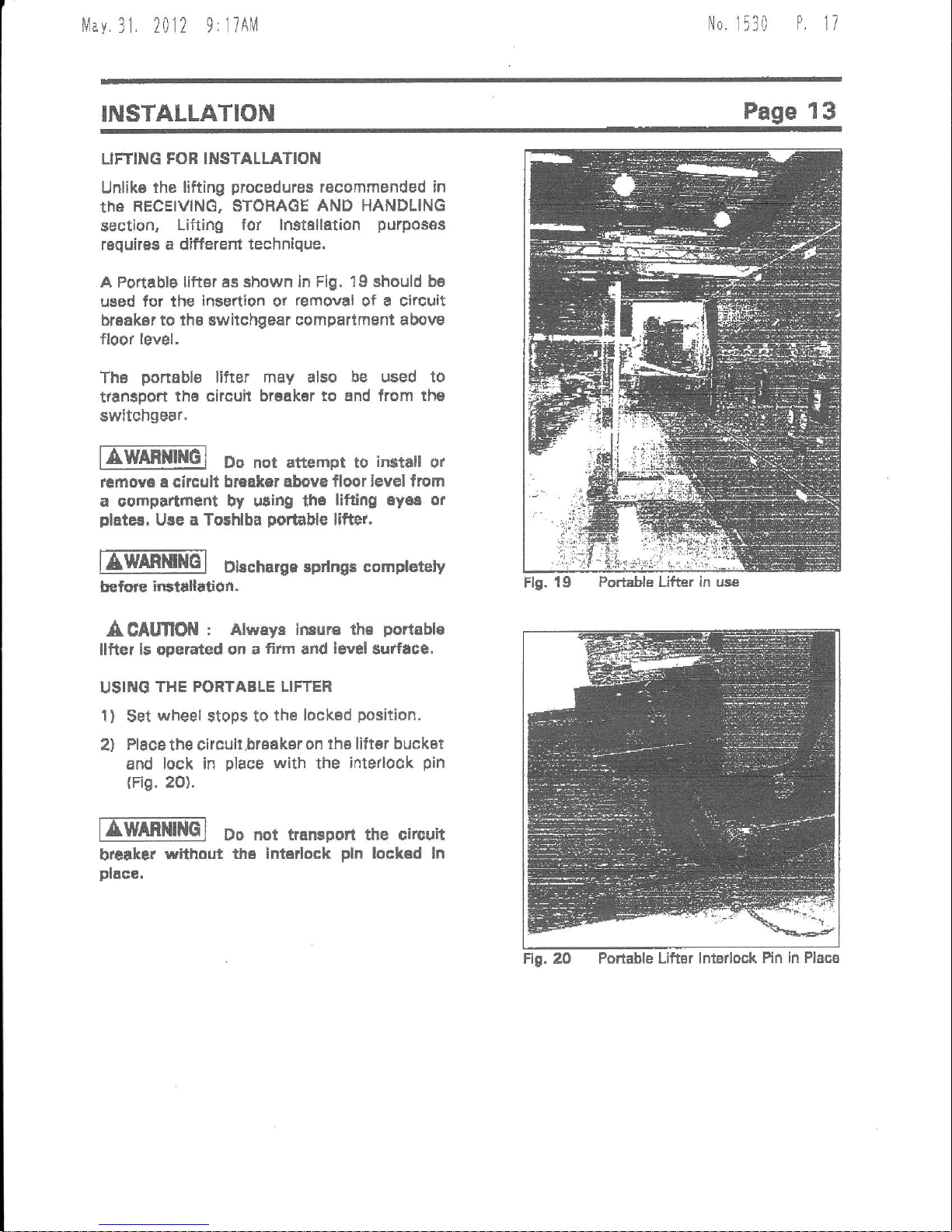
A Portablg
liftdr ss shown ln Fig. 19 should ba
used
for lhe insettion ot
removal
of a clrcuit
br€ak6r to th6 switchgear
compartment above
floor level,
Ths
ponable
lifter may also
be used to
trtnsport
ths circuit brsakar to 6nd
from th€
switchgear.
EWffiMt{6]
Do not
attempt to
irstar
ot
remova
a circult
breaker abova floor level
from
a
compartmefit by uting th6
lifting 6y68 or
plater,
Ure a To5hlba
portable
lifter,
lIffiEl
Dbcharge sprtngs
compt€rcly
ffilre
irHtallution.
A CAtmOil
: Alwaya lnsurs the
portibl€
llfter ls operated
on a
fififi
and
l€vel
Surface.
USIilO
THE PORTABLE LIFTER
1)
$et
wheel
stops to
the
lock€d
position.
2) Place the circult,brsaksr
on lhs liltBr buckat
and
lock in
place
with
the
inte,look
pin
(Fig.
2o).
EEm[im]
Do nor traffipon
the circuit
breraker
without
th€ intsrlock
pln
lockad
ln
place,
Flg. 19
Po*able Lifter in use
ng.2O
Portable Lifter lntsrlock Pin
in Placg
klay
31. 2012
9:18AM
No.
1530
P
18
Page 14
INSTALLATION
lIffil
Do nar rrrEport the vac.um
Clrcuh
Ercaker in dle dc{iNted
pocition
whila
udru
por$lc
llfter,
3l Unlock
the
wheel
stops and
move the lifter
into
position
in front of
the
oell.
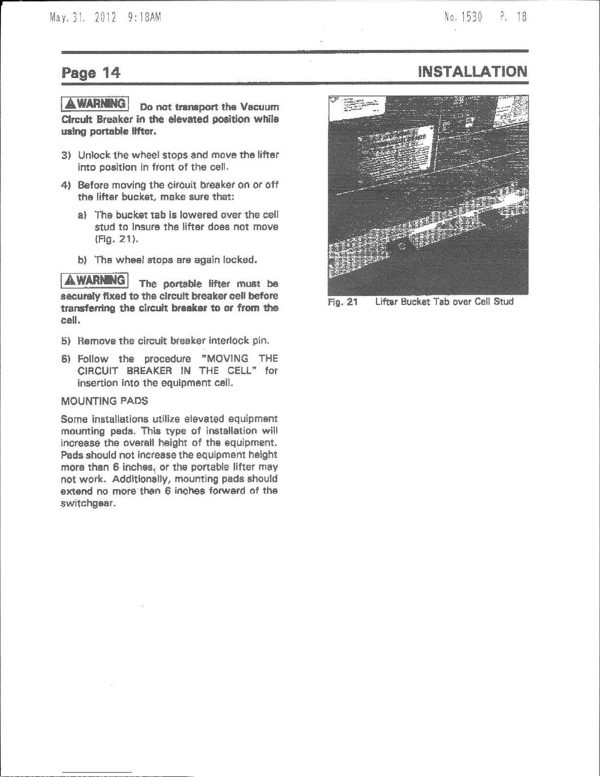
4l Before moving the citouit hreaket on or off
th6 liftor bucket, make sure that:
al The buckst tab is lowered over the sell
stud to
lnsure
the
lifter does not movs
(Fig,
21).
b)
Ths wheel stops Ere again locked.
nmmG]
The
porrdue
riftGr must b6
s€cu]€ly flx6d to ths clrcult breaket cell befu|e
traGfcrdng the cirllir't
k..ler lo or from lha
cell.
5) Ramove
the circuit bteaker
ifiterlock
pin.
6) Follow the
procedure
"MOVING
THE
CIRCUIT
EREAKER
lN
THE
GELL" for
insertion
into
the equlpment
cell.
MOUNTING
PADS
Some installations
utilize
elevated equipment
mounting
pads.
This ryp€ of irEtallation
will
increa$e
ths
ovorell heigtrt of thB Bquipment,
Pads should not increa$e the equlpmsnt
height
more
than 6 inches, or tho
ponable
lifter ftay
not work.
Addltlonally,
mounting
pads
should
ext€dd
no moru than 6
inches lorward of the
switchgBar.
Lifar Buckat Tab
over
Cell Stud
Eq,
2l
|!lav
3l.
20l2 9
r
lBAM
No,
1530
P
19
INSTALLATION
Page
15
MOVING
THE CIRCUIT
BREAKER
IN THE
CELL
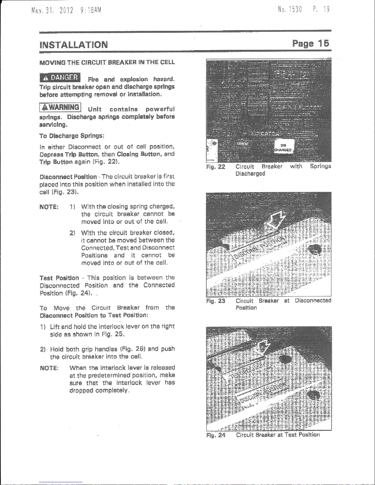
lilE@
Ftre and exptoiion
harard.
Trip
clrcuit
ba€ekar
opan and dlecharoa
sptlng$
b€lore
attempting
lemoyil
or
instellation.
ITMRNINGI
unh
conratns
powerrut
sprlngr.
Discturge ep,ingc
completely befora
rswlclng,
To Dkcharse
$prlngs;
ln either
Disconnect ot out
of
cell
position,
Dep.ess
Trlp Bjtton, then Clo3ing
Button,
and
Trlp
Eutton
again
(Fig.
22).
Disconnact
posltlon
-
The circuit
breaker
is first
placed
into
thlr
posilion
whsn installed
into the
cBll
(Fig.
231.
Fic. 22
Clrcult
Breaket
with
Dlscharged
Springs
NOTE:
2t
1)
T6Bt Poiiffon
Disconnected
Position
(Fig,
Wlth th€ closing spring charged,
the circuit
brgdker
cannot
bB
moved into or out
of the cell'
With rhe circuit
breaker closed.
it cannot
be moved between
the
Connected,
Test
snd
Disconnact
Positions and
it cannot
be
moved into ol oui
of the cell,
-
This
position
is between
the
Position and th6 Connected
24t,
,
Dbconnected
1)
To
Move the
circuir
Br€akEr trom
the
Dbconnact
Fosltlon to
Te3t
Position:
Lift and
hold the inlerlook lever
on ths
rlght
sid€
as shown in
Fig. 25.
Hold
both
grip
handles
Fig,
26]
and
push
the circuil
breaker
into the cell.
2l
Whsn
th6 interlock laver
is released
at the
predetermined
position,
mak€
sUrS that the
interlock lever
has
dropped
compl€t€ly.

Nlav
31.
2012 9:IBAM
No.
1530
0 1/\
Page
16
INSTALLATION
Conneated
Felition
-
ln thia
position,
the
circuit breaker
prim6ry
disconnect
bus stabs
afs
conn€ctod to rhe switchgeal
bus bars.
ln
moving the circuit
br€akdr
from rhe T€st
Po€idon to
trr€ Connccted Position:
1)
First cheak to
mak6 Eur6 th6
open-closad
indicator
reads
"OPEI{'
(green).
Flre and erdoSlon
hazard.
Trip
circuit
br€3kar
opin b€fors attempdrig
to
rack llre citcuit
beaker |trto tte Conn€ct€d
Posldon,
2) Lift
the
ifierlock levar.
3l Ineen
the racking handle
as $hown
in
Fig. 27.
4l Turn
the handle clockwise
(Fig.
28). The
cirouit breaker
will
move inward,
5l Stop
rotating the tacking
hsndle
when
the
raoking scr6w
thread h€s cleared
the
racking nw,
You will
heer e click sound
ae
th6
arrow at the lower
paft
of the cirouit
brsaker
comes in line whfi
the red line of
the Connected
Position hdicating
plal6
on
tha cell
floor
{Fig.
29}.
Remove
the
racking
nandle.
Check to
verify rha intedock
lerrer
has
dropped
completely.
Fig" 26
Gripping Circuit Bresker
HEndles
6)
7l
Fis. 25 Lifting
htarlock Lever
FlA. 27
lnsening Backing
Handle

|v1av.31.2012
9:l8AlM
No. 1530
P,
21
INSTALLATION
Page 17
WhEn drawing
out the circuit braakar
from the
Connected
Po6ition
to th6
Teit
Fosition:
1) Firit
check to mako sure the open-closed
indicetor
r6ads
'OPEN-
{gr6sn}.
Fire
and
exploaion
harerd.
Trlp clrcult breaket open bcfoa€
attsmptng to
r.ck
th6
clrcult
brraker out d th. Connected
Position.
2) Lift thB
int€rlock l€v6r.
A CNfiO{
: To avold equlpme t damage,
.lo not
push
the clo3lng button
lgrEenl
whlle
thc
lnterlock
Lever ii l;fted.
3) lnsen the raching handle
(Fig.
271,
4l Turn the
racking handle coufterclookwise
to mov€ ths circuit broakBr
to th8 Tert
Positj,on.
5)
Stop rotating th€ racking
handlo whsn the
raeking
$crew thread
has cleared the
racking
nut, You will hear a click
sound as
ths
arrow at th6 lowdr
pan
of the circuit
breaker
'$
aligned
with
ths
rsd llne of tn6
TEst Porldon indicaiing
line,
E) Rem0ve
the
racking handle.
7)
Check
to verify the lntarlock
levar has
dropped completEly.
Fig- 2a Turning Racking
Hendlg

Nlav
31. 2012
9:l9AM
No.
1530
P.
12
Page
18
PRE-ENERGIZATION
CHECK
OE
ERAL
BEFORE
ETIEEGIZITUG
THE
CIRCUIT
EFEAXER
for the
fir$t time,
lollow
the
procedure
below
to verify
that the aquipment
iB
properly
installed
and
funotional.
ISE@E
nu2arddu
voltage, Tum
ofr and
lock oui
dl
prim.ry
and control clrcltlt
por,\rsr
sources
tttiot
to
perforrning
ttlS
pre-
energlzadon
check.
nffil
Do not
orerfie
th6
6s$pm6nt
undl
a compleE
safEty inspecffon
hm been
mede.
nwARmG]
Do not enerEize
dsffaged
6qrlpm6nt
that ha3 noi
bsen repalred
or
vcrified,
Eml
Do
nat remove,
cover or
destsoy
iny safew
6igrB.
fllffigl Do not operEt€
th," .qrrpment
uftil all
pand$
and
Govelt
hav6 b6an
rcplaced.
n Prior
to
operating the
clrcuit
br€eker,
be
su.e that
thG citcuit breakel
unit
is installed
in the
correct cell.
tr
All block or
oth6r t€mporary
braces used
lor $hipment
must
be
removed,
E Before
alosing
,the
snclosure, all
mstal
chipe, scrap
wire snd othel
deblis
left
over
from
instelletion muBt
bs cleanad out.
E
Cover
all
unueed openings
in
the circuit
breaket.
cell
r all
ELEC'RICAt
CHECKS
nWARl|[Ql Eecrrical
shock
not
touch energlzed
components
u$ng
auxiliary
Power'
panels
and covars.
tr A
Eupply ot epEre
parts,
fuses, etc.
should
be
e3tsbllshrd.
I lnstructlon
manuals
snd
diagrams should
be collected
and
filed.
n
Replace
all
pans,
guards
and batriers
that
may have
b'een
rEmoved
during
wiring and
in$allation.
hazard.
Do
during
a tert
D An
6l6ctrical
insulation
tesistance test
should
be
performsd
to verify
that the
circuit brsaker
and
associated
fi€ltt wiling
arg
fres
from shon
circuits and
grounds,
Refe/tothe
MAINTENANCE
SEction of
this
manual
for additional
information.
EmllRlrB[q Hazardous
vortages
are
pr$ent
.luring dialEctrlc
testlng
whlch can
reault
ln serious
iniury
or
daath.
High
polentlal
taat3
should be
parformed
only by
qualified
peftonnel.
. All
switchos
dnd circuit
breakers
must be
sel
to the OFF
and/or OPEN
positlon
befors
Bnergiu
ing incoming
Powet'
the
llanual GLOBlllG
EUTfo
Fig.
3O
Typical From Circuit
Breaket
LeYout

lvlav
31 2012 9:
19A[1
No,
1530
P.
23
OPERATION
Page
19
MANUAL
OPERATION
ITWmmo]
powcrfl
spdns6, Do nor
place your
hends or iny
part
Of
your
body
inside
thi$ equipfient whlle any lndlcator
ahows
"CHARGED' {yallow)
or
'CLOSED'
kedl.
A.
Manual Chdrging of Closing
gpring
(Fio.31)
1l Rgmove
tho charging
handle
cover,
ldsert
the charging
handle into the
opening for th6 manual charging
handle.
2l
Rarchet
tha
h€ndl€
up and down
several tirnes
{u$u8lly
7
times) untii a
click
(latch)
sound is heard end tha
closing spring chargihg indicatot
changes
fioilt
"Dl$CHARGED"
(whitel
to
"CHARGED"
(yellow).
This is the
position
wh6rB th6 closing spring
is
charged and no
further
movement of
ths handl€ is required.
3) Remove the charging h6ndl6 and
r6plac6 ths cover
plat6
to the Opening.
NOTE:
The number
of times the
handle
must be opefsted
depends
on the
sngle of handla oparation.
B, Manual Closing Operation
Pueh the manualclosing button
(green)
and
th6 circuit braakBr will close
(Fig.
32).
At
this time the open-closed indicator
reads
"CLOSED"
(rad)
and
th€ spring charging
indicaror
turn3
to
"Dl$CHARGED"
(whlto).
A CAIIIIOII
: To
dvoid equipme r damage
do not
push
the closlng button
lgreenl
whlle
th3 clrcult braakar ia closad.
A CNmON
: To avold cqulpment damEge
do not
puNh
th. clo3ing button
lgrEEnl
whil6
the
ffp button
lred)
i$
depressed.
C.
Manual
Qpening
(Tripping)
Operation
Push the trip bwton
(red)
and the circuit
breaker will open,
The opan-closed
indicator
{Fig.
33} will
r6ad
"OPEN"
(greenl.
Fig,32
Fis. 3l Msnusl Chsqing
of Clo$ing Spring
Circuit Br6iksr
Clo€dd
Fig. 33 Circuit Breaker Trlpped
Open

tvlav.31.
2012 9:19AM
No.
1530
P.
24
Page
20
OPERATION
ELESTRICAL OPERATIOITI
Elsctrical
opetation can
ba carrisd
ofi at the
Ts$
or Connoctsd Pqsition.
when
tho
clrcuit
breaker
is
outside
of the cell,
it can be
operated
elegttically
by using
Toshiba
lntarnalional Cotpotdtion's
Sccgs$ory
lsEt
oabinet.
nffiq
powarfut
Spdngs. Do
nct
place
youl
hanrb or any
pan
of
your
body
imlda
the eqipment
whih
indicstor rhows
'CHARGED' lysllorv)
or
"CLOSED'
(r€dl.
Effiffil
66""L
crrcuit
breaker
namedate
for verification of
prop€t
oPeradng
Yohags,
A.
Eledtricel
Charging of Closing
Spting
Upon
applying
power
to tne
conlrol circuit,
the
charging
motor will immediately
start.
When
the sprlng
is
charg€d, the closing
spring charging
indicator
turns from
"DISCHARGED"
(white)
to
"CHABGED"
(yellowL
and
tie motor stops'
The spring
charging is now completod.
B,
Electrical Cloeing
Operation
When the
clo6ing switch
is turned to
"CLOSE"
position,
the
closing coil
will bs
immedidtely
enorgizod
and the circuit
bre€ker
will close. The open'close
indicator
wlll
th€n
tead
"CLOSED"
(redl.
After tho
clositrg
of the
brsek6r. tha
charging motol
will
immediately begin to
charg6
thg
olosing
dprings. Upon
rhe
completion
of
charging, the
closing
spring
charging
indicator
will read
"CHARGED"
(yellow).
6.
Electrlcal Opening
(Tripping)
Operation
Wh6n
the trlp switch
is
lurned
to
'TRIP"
position,
tha
trip coil will be
imrnedistely
energized and the
circuit
breaker will open,
wirh
ths open-closed
indicstor
reading
'OFEN'(greenl.
cor\lYRol ct RcutT oPEnAnoI\l
A, Closing Sequence
Th6
schematics $hown
in Fig. 34 thru
Fig.
36
r6fl6cts
the condition where:
1)
Ghatgtng
13
complate,
and
2)
Th€ circuit breaker
is
open.
IVOTE:
Thc closing
spring
immedi8tBlY
begins
chalging
when the control
circuit
is energizsd.
Pour€rful tprlngs
and movlng
geare,
Do not
plaae yout
hands
of
eny
part
of
your
body lnslde
the equlpment
whil6 tha
cl.cult brcNLGt
it chrrglng.
ln this condition,
the external
opBration
switch
cs(1|
is turned to
the
"closEi
position
causing:
1) Circuit
lL, b1,
LCS,
Y'b, X'b, CC to
energize
the
closing coil
CC,
in$tantlY,
end
2)
The circuit brsakar
closing
llm.
18
304O
mcec., at which
tiffie,
3)
Auxilidry
switch b1 opens,
4) Closing
coil CC, d€-€nergiz€8.
5) Auxiliary
relay
Y,
energizos,
completing
th€ anti-pumping
circuit.
B. Charging Sequence
At
the same
tima tha
circuit breaker
is
closed:
1) Limit switch, LS,
closes
2) Control
Felay X, enargizes
3) Circuit
LS, LS,
X-4, M,
X'4. F is
complered,
and
4) Charging
motdr
runs
(for
about 4
eec)
When oloslng
spring
is charged:
1) Limit switch,
LS,
opens.
2l
Control
r6lay
X, de-energizes.
C. Tripping
{Opening}
$equence
The
tripping
of the circuit breaker
involves
only
the a l
,
TC citcuit.
when the extelnal
oporation switch
GS(21
is
turnsd
to th6
"TFlP"
position:
1) Trip coil, TC,
engrglzss,
and
2) Chcult
brEake. opening
ot tripping
fime
is 15-20 maec,
At
which
time:
1) Auxiliary switch
A1,
opons
2) Trip
coil,
TC, de-anergizes
IIOTE:
FOr clrcuit
brsakers with different
valtagE combinationg
lor cloaing,
tripping
or charging,
consult
Toshiba
lntgrnational CorporEtion
tol
the
particulSr
schEmetic.

Mav
31, 2012
9:l9All
No, 1530
?.
2,
Page
22
OPERATION
FiC.
36 20S250
VDC
ContIol Circuit
Schematic
SYMBOL
DESCRIPTION
Auxiliary rslay coil
Y-b
Auxiliary
relay cofitedts
(N,0.)
x Conuol
relay coil
X-a Control
relay
contacts
{N.o.l
X.tt
Contlol
rclry contacts
(N,C.l
cc
Closing
coil
TC
Trip
coil
a1{5
Auxiliary contacrs
(N.O,l
bt-b5
4ur;11"ry
q6n166s
{N.C.}
M cherging
motor
LS
Limh switches
DI
-D5 Diodes
RI-R4
Resistors
IL lntor'lock switches
c
Cepscitor
F
Fuse
Lcg
Latch Checking
Switch
Hg,37
Legend for Co rol
Ckctrit Schamatics

Nlav
31. 2012
9:l9AM
No.
1530
P,
26
OPERATION
Page 23
l-8 SN" end doGlng
$dng
dlal!€d
t-5'oFF
Clodng €igr,Ll
slrn o{ dGln! op€rdion
Cdlnpleuon ot do8lng op€rdon
1.3
!Ol{i
rnd deing rgnrB
cfierged
Stai of healdng
operuisn
Flg.
38
Sequance of Opgration

l/av.
3l. 2012
9: 19Ali1
No.
1530
P.
21
Page 24
OPERATION
trip
cacch
trip
coil
c ioEing
sprilg
Cl
oei ng
Vac
lrum
inter!uptef
paddle
Closlng
eoil
CloEing
Trip
paddl€
catch
Wip6 rl)rl
CloElbE button
openisg
spring
\
I'taid
Ehaft
Flg. 39 Mechanist$

N1ay.
31
2012 9;
20AlV
No.
1530
P
28
OPERATION
Page 25
MECHANIgM
OPERATIOITI
fAlmml|Fl
Do not
modify or ovedosd
thc
clrcult
breaker operati
g
mechanism.
Slow
clo:ure
of the broaker could
re5ult
in file
and
explo6ion.
A. Closing
The
condition
shown
in Fig.
40 repressnts
the condition
whete the oircuit
breakst
ls
open
and the closing
spring i$ charged
(ready
for cloringl.
ln this condition,
tha
closing
catch
is
released by the
closing
button
or th8 closing
coil, the
closing
spring
csuses the cam
lo rotate
quickly
into the condilion
shown
in Fig.
41 in
which
the circuit breaker is
closed.
B, Charging
From
ths
closed condition
ol Fig.
41 only
the closing cam
is rotaled
by
tha
motor,
with thB
circuit breaker kept closed,
ufiil
the
roller on
th6 cam sngages with
the
catch.
Tripping
Wh6n
thB trip Bhaft ig released
by lhe trip
button or the trip
coil,
dll tha linke raturn
to
the original
open oondition
shown
in
Fig.40.
Trip Free
Whed the
trip crtch
ls r€lea3€d,
tho link
will
move to the trip
free condition Shown
in Fig.
42. When rha charging
operation is
completed,
the
link wili
asBums
the open
condition.
Fig.40
MechanismOpened
D.
Fig.41
MBchNniBm
lmmEdiBtBly
attef
Closing
by Signal
Fig.42
MschNnism
TriPPed
Free

ltlav
31 2012
9:20A1vl
No, 1530
P.29
MAI|uTEilATIICE
PROGRAI$
ln
ordgr
lo €nrur€
continued
reliable and safg
opefatlon
of
lh€
equipment, a
program
ol
routine
maintenance
must
be eetablished.
Operating
and environmental
conditions
will
u6ually dictst€
thE frEquency ol inspeotion
rBquired.
NFPA
R.lbllcatlon
708
'Electrical
Equipmsnt
Maintenance"
may be usad
as a
guide
for satting up thE
maintenance
prog6m.
f@@il
contact
with .netglzed
GomponeBt3
Gan caut€ ievere
iniury, .l€eth
and
Foperty
<lamege.
Tum-off
and look out
hlmary and
Corttol Citcuit
Powar bofore
Ser1,icing.
|AUARlllG-l
tmoropor
matnt€nEnc€ can
c*l86
selrEr€ lnJury.
dsath, and
prop.rty
damage.
Only
qualified
and
aut}odzed
peBons
are
to irstoll.
operatE,
or r€Mce
thls
eqripmBnt.
Do not
allow
grrlte
or lny
othsr
subetancs
to aontaminate
any
intularirq
materl6ls.
Gofteminated
lBulatots oan
allow
8 rhort clrcult
ot
ground
fauh to occul.
iIOTE: Refer to the SAFETY
section
of this
manual lor imPonant
information.
MAIII{TEIIAT{CE
HECORD
Keep
a
p6rman6nt
record
of all
maintenanca
work. At
a
minimum, this
r3cord should
lncluda
information on:
Item$
inspec-tlon
Repons of
any testing
Equipmem
condhion
Corrective
actions
or adiustmems
Dat6 of work
Comments
The
degrss
of detail of
the record
will
depend
somewhat
on the
operating
cond ions.
Teblg
2.
Gircuit
Breakor
Recommended
Torque Valuss
TablF
3. $witchgear
Rscoflmandad
Torque Values
1)
z',r,
3)
4t
5)
6)
Hardware
Size
Recomm6nded
Torque
M3
M4
M5
M6
M8
M10
M12
{kgf-cm)
10
20
40
80
200
350
450
(ft-tb)
0.7
1,4
2.S
5.8
16.5
26,0
33.0
Hardware
Size
BecommsndBd
Totque
1t4-20
5/16-18
3/8-16
1t2-13
(kgf-cm)
55-83
138-207
276-415
553-691
(ft-lb)
+E
10-15
20-30
40-50

ftlav
31 20l2
9: 2OAlVl
No
1530
P.
30
SERVICIITIG
EOI,IPMENT
For
your
safety,
turn ott and
lock out
main and
control
circuit
powel
betoae
servicing
th€
circuit
brsek6r.
Should
ssrvica to
thB circuit bleaker
bo
required
while
tho system
remains
energized,
enrome
caution ust be
sxarcisdd.
Al8o,
certain minimum
safety
procedu/es
mu$t be
followed:
1) Only
qualtfiad perronnel
should attempt
this
38rvic6.
2)
Oo not servic€ a
eircuit bteaker unit
while
connected
to ths
line lerminals.
withdraw
the de-energized
circuit
break€r from
the
anargiead main
bus before
sgrvicing.
Never sE.YicE the
olrsult
breaker
whlla ln the Cormeoted
Porition.
3) Verify
that the automatic
Iine tsrminal
Ehutters
are
closgd, Ilcver service
a unit
unless
the$6 Shutters
ara
fully closed.
4) ltleve.
perform
s6rvic€ on
or next to
exposed components
energizEd
with lin€
volteg6.
lIfimFildl
Fairure to adhere
ro rh€s€
ittety
pmc€durt3
can
tG8ult ln 5everc
iniury.
death ard $evere
prop€rty
damagB'

l!1av.
31.
2012 9:2OAM
No.
1530
0 11
,)
Page 28
MAINTENANCE
INSPECTION
AHD MAIIITENANCE
TYPE$
IUOTE: Refer to the
SAFETY sactlon
ot
this
manual lot impqnant
intormation.
For
points
and types
of
lubtication
refer to Fig. 43
A. Acc€ptancB lnspsction
This
inspaction confirme that the circuit
bredke.
unit
ie completa, corr€ct
as
epeciJied, and undamaged
from
Ehlpmant.
Th6
procEdure
for this in$pection
ls
outlined
in ths BECEIVING eEction of
this
manual.
B, Ftsfiol ln$pection
lnspection
of the condition
of th€ circuit
breaker
while energized.
1) Check
thar no unugual sounds or smolls
exists axternally.
C.
Vi$ual lnsp€otion
lnspection
perform.d
with thB circuit
breaker
withdrawn flom
ths
switchge8r
companm6nt.
I
)
Wiih front
covet removed, inspect
entire clrcult breaker
fot deformation,
ruai or any other
typss
ol
abnormalities-
D. Periodicel
lnapection
lnspec on
parformed
with the circuit
bteaker
withdrawn from the Bwitchg€ar
companment.
1l Psrform Visual lnspection.
2) Clean and lightly coat the contacting
gurfac€s
ol rh€ main conductive
pans
with
Toshiba
B8
greas€.
3) Close
and ttip circuit br€ek€r
manually
and alectrically to
insure
Proper
operation of
m€chaniom.
ChEck wiPe
measurement
(Pg.
361.
4)
lnspect to insure
lubricadon of sliding
end rotating
pans.
5)
LubricEt€
sliding and rotating
parts
with
machine oll
ts
r€quirod.
6)
Test
the clrcuit
breeksr to inaurB
that
primary
and
$econdary
circuit in3ulation
reeistances are
within Toshiba
lnternetlonal
Corporatian
specilications
(Pg.
35).
E, Detail lnspection
lnspection
performad
with
rhe circuit
breaker
drawn outside
of th€ switchgaat
compertm€nt.
1
I
Parform
Periodical lnspefiion.
2) Re-grease
sliding and
roteting
part8.
Feplac€ cotrBr
pins
and E{ings that
are
removed
with ngw ona8.
3)
Perform diol€ctrlc
test
(s6e
Vacuum
Chack
on Pg. 37)'
4) Test the circuit
bisak6r
to insure that
closing time
(Pg.
201,
openlng
timB
(Fg.
2O)
and minimum operating
voltages
tPg.
48)
of
bolh the
closa and trip coils
ar€
within
Toshiba lnternational
Corporation
sp€cifications.
F.
O\rernaul
Complete
di3assembly
of circuit breaker to
replace worn
pdrts
Es
required. Clsan and
re-greaae all
parts,
To
be
performed
only by
Toshiba
lntgrnational Corporation,

[1ay.31.
2012 9:2oAM
No.
1530
P,
32
Olh
or tO
vAc.+N: or-
O&
cr
:5C
,rcsir rA E6 cRlcsE
o#
cr
r&o
ro
Nor
-uERrcAiE
cl coN-AVl."lA-
t{,Tr OTIER Cr'-s Cl GiA{S:
b:tA| A
(sHcwN
DTSASSEVBLED)
:)fi:RNAL
Pc|l-r S
I\'TERNAL PCI^ES
Flg, 43 Points and
Type6
of
Lubricetion

Mav
31. 2012
9:2OAM
No.
1530
P.
33
Page
30
MAINTENANCE
INSPFCTIONANDMAINTST{AilCE
INTERVALS
Tho frsqu€ncy and
detail ot
the required
lnspefilons
will vary
depending on
th6
anvironment
of service and type
ot
inspection
to
be
performed.
Ueing Fig. 44 select
between
the
charts oJ op€rating
years
and operating
cycles
which
will reQuire thd
most fr€quant
inspections
and maintenance.
ln addhion,
when applying circuit
b.eakers
in
severe almospheric
sites such as
outdoor
companftents
,
dusty
gnvironm€nts
,
high
temperaturss
and/or
high humidity
the
inspection and
nrairtanenc6 frequency
should
ba. at a minimum,
twice as
oft€n.
lf th€
1 2th
year
overhaul
is not cetriBd
out, ths
Detsil lnspBction
should
be applied
in
the
cyeleE
of ths
Psriodical lnspaction
(every
3
years),
Should
the circuit
breeker
ba
subiEcted to a
sev€re
condition such
as drop,
collision,
earthquek6
or
fire contacr Toshiba
lnternational
corporation
for s compi6ts
inspection.
lgpldoh
&rpFfrn€ & Pra4llcl!tssn
Ctpdt
l6dnl
I
Frio.Hl
ItlHr
gerdot!
ln+€roolt
AcEsFsnEa i
PllEsnrEtsdl Clrd(
Vlllnll
Pdiddiod
I
0
1000
4000
0000
4@
5000
5000
7000
d0d0
9000
10000
Fic.
,*4
lnepection
Frequensy Schedule5
fffir@t
ablpdudE'ign
9.CtFd(Ublb#n
a uidcdrth
ol
[.
HanrE haddon
Fd.EB
6.R.{rE
7.
Dlalacllc Toa
Chsd(
ffir1!6?V&urlt
8. OprdB
Cll."dtHc
ll.sramst
g,
Oodvlda
D5*ni6t {d Hetdld
Fig.rlS lnepection
and
Maintenance
Tree

llav.31
2012 9:20AlVl
No
1530
P.
34
MAINTENANCE
Page 31
at
.v
(E
[,
rc
c..io6
-g-p(\
€€^-
FFE
oG
6N
.ct ;
Pd
o
tt
o
E
ts
o
o
o
!
cqi
PE
r-B
Etl
ond
tL-c
F.
oqrE
-ooi
cE8
.c .>
,:E-
B50h
O IJ{!
L
;olEE
5 Et
-Ct
3t
tl
E
o
A."
8H
9o
ss
dP
CE
+rlt
9E
oR
G-
fig
.EE
oo
lEc
si
_r
Ntr(:
:4C0.
E'E E
E.96
Ee_
!t
r: H
8EF
s-g
H
ohle
IECLf
!il
f,ft
.=B
9.8
luo
EC
9o
d
3b a
8E
-
8
Eol>
€HEE
EEE€
F
(J
o
.Bd
-a
+;
6E
fiE
6t-
E5
bE=
t;g
:€:
'i8E
EEEE
o
'6
6Ul
3EI$
9iE
Jcl6
.EEE
gIEE
oi,
Een
f€;
e
B
3
-c)
EE
Vrg
6r .=
g
.st
FE
E
oo
EE
*E
EE
JIE
EE
l,ra
'rE
oq
3!'
'l
qo
dg
o
ot
d
-t!
tGd
oEt_t
tc.F.
cr:8
!c@r
d;eFl
(J-c;rit
EXXO.
IJJOEla
Es
.t-
p9
EE
{',E
.g!
to
;83
E9g
tr- ct rl
o
E
!0
=
J
I
E
(J
8
.lr'9
oil
.e
8g
O.E
B
ET:
gEE
J
(J
6
(J
6
:
t,
IJ
o
.tr
()
E
.!
()
d)
E
U
(c
o
{,
qt
r'P
C
r-.P
OEE
E**
f !1 E
g€E
J
u
I
iJ
:t
lt,
5
J
t)
s
a
.q
E
o
I
C'
6
.c
(J
o
8e
o6
E}
,lE
,9E
F_C
o
c
9E
:.6
t, @
d.P
c,
r0J
838
'tl
a.l
fit
.E>E
EE€
EHE
ED
c
'd
ct
.E
o
-g
g)L
oo
JEI
vt
o
dL
tl
5
IA
g,
5
.D
o
HB
o6
otr
trd
ulE
E
c,
3
T'
E
ll-
o
o-
J
(J
t)
(J
o
:s
-
0lE
6'=
-l
l,
ts.= P
=
l!(J[d(,l
o
z
.A
J
d
llt
F
z
;
t)
z
z
r!
F
z
a
2
o
z
z
o
tr
C)
ut
c
ah
z
.F
o
F(.l
,EE
6E
TR
E6
!c
*-C
o.-
r.-
O
oc
!o
.t Tr
-Eo
tE
o:
so
96
1E
l!u
-o
{t
F5

flay.
31.
2012
9:20Al!1
N0.
1530
P
35
Page
32
MAINTENANCE
o
_v
c
=
o
E,
c{('(o
o o({
iFfl
t-t-v
o
E
o
E
s
=
a
o
E
CL
!t
c-->
6H;
I
oB
5C6
t.E s
ahSi
8r
-d
sfl
EH
FC
o
o
ad
CI
6
o
Pu
lio
ct6
oo
.EE
ah
F
o
o
6
o.
o
o
.E
,=
dt
q,
tr
e6
ori
IEE
ct
EC
E'6
.F
.E
e>
oll
bo-
EEE
TZEO
o
o
U'
f,t
3E
gE
'=o
E!.
b9
64
AE
o
c
o
-t6
IEF
e-
tto
6!J
-t,
Ir0
d E'6
o
E
6
.ia
o
o
E
oP
> e-a
b'c 0t
tt
_=
!l
o'a
trbo
I
eE
E'i ta
E''E .
6Pig
gEg.E
F
CT6
O
d)
5€
Ed!
()c
E>
3E
oQ
.E
ci
E.,e r
d',o,-g
3E;
{fi;
co
._
ED
>.c
P E'E
E8R
.ov
.D otE
.
E.efE
a-=6
ED
it
=
>
-:J-O
a, E= o
Ei{e
E.9du
EEAE
Or
tr
-a)
E.d
EE
-o=tD
-e4
6Jc
S":BH
q€
I
EE
gri;
FE
.aE
EFl-
FFEEH
aqooEdl
u) ca
ara
T'
c
o
att
:
E
o
c
o
-!!
=a
YF
o-
o6t
oQ
nt
'cl
E
5
9
rlt
.9;
'EE
oo
o.tr
o;
.l
c
o
o
E
att
o
o
€
a
f
E
E
.c
o
E
!
(t
o
E
(J
J
TJ
ID
"c
(t
EI
:
ab
dt
ttt
.4' I
(,
i:
O.C
aa
6EB
ET:
60.
9ti
.l
(,
I
t
o
:
-o
.t
tJ
o
E
o
F
f
p
J
C'
o
a)
!d
l
o
r'9
lo
g$
E
o
rri
it .E
c!
t'o
e?
6E
..v
o
c
E
o
E
E
o
g
!
o
E
.c
o
F
E
B
{
st
.E'j'
!r aJ
co
:rc
ot
68
E
F'
dsi9
A
E.E
BgE
(J
o.o
ta
tr
-g
a
o
EI
att
o
td
!rE
6h
an(D
de
c
FO
Oftt
Pi
EO.
t,/)6
oo
-!l
o-
60
uc
llF
fo
l.o
Ed
cr,
Fg
'6
o-
6rr
UE
E
tJ
o-
o
o
E
o
6
ib
'\'
cD
g
ct
o':i ia
o
!jYOI
fii5fi6
E>
cD6=
EEfiE
"8gEE
o
z,
-
C
o
o
c
o
E
o
I
o
c
o
ut
c
,6
!.
J4
ct
rD
E
(J
+
-c
.o
6
F

N1ay,31.
2012
9:2lAM
No.
1530
P.
36
MAINTENANCE
lt
it
E
g
o
E
ID
lq
rir
d-
t\
d)
ED
m
n.
o
EI
o
E
3
=
E+
htso
o-P
.>J.E
cI-o
o
qE
E
<tdtr
ED
tr
oE
E Ic
E
".o
CEE
oio
tr O, IJ
"-9-l
.g
F.q
;
>:c
-.=
H;
Ee
F.: bq
=---v
EE.Bsr*
fi.s E E-9
o
8.HE
'=
o ar.E
frE
sf;
}EEd
-E
'.=
:1 0
tr $F;
oP- o
,EE; E
P
fi;g€qE
FE.E:E
HF
':
oF
-e€.o
ti t!
0!
ln
Ed
gFF€
s_96-9
>oust
6
o
E
TJ
*
o
o
E
ttt
E
6
E
i
f
E
-b
o
o
o
o
i
o
o
E
t4
Ei
FE
ho
tso
ecl
o-
c,6
(g
I
c
o
i$
6
lr
E
o-
o.=
-c
dr
6q
!t
.i
*g
.sE
o
o
d,
an
.l,
o
6)
.c
(J
E
(}
d
ql
ff
g*Et*El;EE
:Ett
SEis
gS
g
fig€E?E'EEE
EH;cEic'E[;
.9d
ou
E,p
.l
6e,
EE
€s
tr!
tr
lll
{.1
c
uF
3rJ
EE
nL
o
lll
O.!E
FE
E
o
-c
o
E
*
o
()
g
u
!)
(l
E
o
c
o
EJ
oo
tro
3-c
l!t
c
E
t!
!E'i
d<cD
*rE
6)
o
O
.y
(,
o
o
.g
E
o
!
.v,
l,
E
u
E"€
Elo
ED
O'
.c .E
tt
cl
oe
ots
'io
E5
E#
c'=
E6
c
6
B
(t
o
(J
-(D
$g
bllP
EE€
rEHB
c
.e
ct
E
E
6
c
d
o
c
o
6-
J
o
6
o
rEF
EEEE
s9: a
o
tct
f=
(r0
gE
o
z
3\l
('I
I
o
o
c
o
u
o
o
u,
E
o
0,
.s
o-
J
o
GO
.c
o
+
o
E
to
F

Nlav
31.
2012 9:21AM
No. 1530
P.
31
34
MAINTENANCE
-
tr
e
tJ
c
o
E
tJ
I
{,
;
o
o
E
-9
o
@
-c
(J
+
.c
tl
.!
F
E
J
E
tr
o
ts
ro
s
o-
o
.i
IL
o
|Et
o
e
..c
B
t
o
t
.9
o
E
tr
6
l1
B;
orD
OED
.qE
oE
lgE
e r
ai6
E:3HE
B
E
5
E8
! 6-d
.D
-
H BEIOSi
ESFEE;
fEc;Ff
g
p6E
6_ d
o
€Hg E
EE€e€
ifr
Hr
gn
65EtE.E
.E
6
6
sg
:Ed
cE
UC
t!
Tl
E>
@c
tEd
0!+,
u.tr
€:E
abH
E$rs
:OEE
b bo E
lfo6o
oc>€
# o
-o,6
'oA-
t.c
o O
n
o
.C
(J
@
.A
o
s
o
c
E
4t
E
:!
o
-c
vt
zi
p3
6p
FS
g
€
E
tt
E'
o
.s6
ofr
:fe
ot
t.9
oE
Os
.co
Ftr
e9
T
sE
E
E$.qE
dEEE
.gOEH
oEdE
EEHs
, E?Z
$EgE
F bi:
t
9o
it6
.g
13
io
o
E
trc
EE
'Hes
tf
,=
-c
t'qb
oo9
s
ttE
l(Jgt
o
c
6
.a
E
o
66
:9t
9r6
ob
4F
FE
-o
'=o
rgd
d6r!l
a! l't
.E=
oS
6
Irgo
::.ct
I'
EEE
E88
dF
-.
F oii
^El
L
o
E
J
o
o
E
c)
EE
glr
9B
,c6
Fh
L
(J
o
o
a
5
J
(,
o
E
o
E
-a
E: F
'eB
E-
:bLE:rlD
L
o
tr6.E
;EEE€
srepE
ll
tJ
c
u
(g
3
,A
!
o
o
o
6
.2
ID
=
-/,
.J
o
a
c)
.9
6
c
E
o
F
?E
oo
$F
lEfl
e€He
E-l
6E
ED*'J
r E.E
E:FE
o!6
o
€6
:JF
ox
EH
c!-
o--
(J6
0
G
,.9
u
c
c)
et
3t
4at
ut
(.)
o
lE
FO
co
.=6
ii5
I .iJ
c()
6.:
(J(J
th
rE
o* Y
F
r.!
E
6ts:F
9E9H
d9i5E
o
z
rt
tro
ao

May.
31.
2012 9:2lAM
No,
l5l0
P
38
MAINTENANCE
Page
35
?a
+
6
E
o
t
o
10
o
E
-c
3
c
6
o
E
G
t
.F
P.
<-b
5E
o
T'
o
"{
od
.EE
(Dts
rr)
-E
srt dr
i-lDc!
o.=
(o
!:5c
,E E€
€ErH ;tg
ESEeEEEH
eSIFBEuF
:EE€43!H
CH;ts!EEs
tsEfbE.EEE
.E
a)
o
o
c
a!q
n.gt
rQ
.trE
(4
E;
osQ
9s6
FEtr
PS
EF
ld .d
:lE
o,
Eo
oJ
be
FO
qi
o
ED
{J
E
o
o
o
o
o
to
o
o
o
c!l
oY
EE
=o
att o
EE
o
a
E
oP
o9
loE
o
E
od
EE
r.r E
o
E
o
=
8E
ll'L
tt
:o
c,E
t!6
oat
Eo
.=
o
';i
Er
c:1
,EP
>ct
=,ll
-L(J0
u ao
-u
Eb
lc
6E
dE
o
.g
a)
=
J
.J
CJ
.c
u
J,
o
o
o
tg
.?,
E
at
;
t)
6)
_-
u
5-.
E.E
g
.EgE
gEE
Esp
ct5e
tr
'6
(L
a
o
E
u
-o
ofgH
3;E E
,
9or
tr
co
o oc
l
=It
n
-:l.
tA
E ;'4
=
o:E
o
z
.o o
-
o
u
o
o
o
o,
$
o
th
tr
'6
d-
J
IJ
4
E
U
rt
['
t
6l
F

Nlav
ll 2012 9:2lAM
No
1530
P 39
Page 36
MAINTENANCE
wlPE MEASUBEMEIVT
when
the
clrcuit bloaker
is
closed.
pres.Bwe
on
the maln comact$
inside
the
vaouum
interrupter iE maimained by
a set of springs.
As
the
mein contacts inside
the vacuum
interruptet
wear,
the amount of
wipe
on the
springs decrcases.
Wipe is used to
measule
cofttact w€ar and
maimain contact
prsasure.
The docrea$e
in wipe
i$
also
u$ed to det€rmin€
whsh to
replace the vacuum bottle due
to
wsar
of th6 contactg,
iAmfq
J{6v61 use
a crrcuh breaker
wlth
insufficient
uripe. lnsufficient wha
will
cEuas
poor
cor*act
prcrsute
and can ru$ult
in
firi.
arplosion, ewere lnlury,
daath and
p.opeity
d6mage.
EWAsllG]
rvau.r
aqu$ the wrpe of a
vacuurn
i
terrupter-
lmpropsl edjusrrnent
of
the wlp€ can rcsult in fte,
explo6ion, Sevele
iniury, daadl
end
Flop€rty
damag€,
For: 6M32A
1OM25A2
6P32A
r0P25A2
5M40A
l0M40A
6P40A
10P40A
8M4OA
8P4OA
Wirh
th6 circuit breaker closed,
visually check
the
wipe mark
(redl
ae shown
in Fig. 46. Tho
irnerrupter mu€t
be
replaoed when
tho
wlpo
mark ia no longer visible.
an'n t
FLrLL tt I P=l
I3- MAtrK
t
R=Dl
FiS. 46
wipe
lnspection
PLATE
r-lmm
C;ULL
wlPE)
fig,
47 Wipe ln6pecdon
For:
5M50
6P50
6050
8040
10040
r0Mso
10P50
10050
With
ths circuit
breakar clos6d,
measure the
wipe as
shown in
Fig. 47. Ths lnterrupter
mu8t
b6 roplac€d when
the bldck extends
1mm
below
the
plat6.
.
All
servicing
and replacemem of vacuum
interrupters should
bg
done by Toshiba
lnternational
Corporation, Consult the
factory
for
further
details.

Nlav
31. 2012 9:21A[/
No. 1530
P.
40
MAINTENANCE
Page
37
VACUUM CHECK
This
test
procedure
ls
provided
to oveluets
tha
dielectllc
lrnegrlty
of the
vacuum
interruptgr.
Ths rslatiomhlp
bsrwsen
the dielectric
breakdown
voltaga
and internal
vacuum
intarrupler
preEsure
has
been
found
to
b€
gen€rally
pradictable,
NOTE:
ApplyinB
abnormally
high
voltag6
acrogs a
pait
of contacts
in vgcuum
may
produce
X+ays. The radiation
may incrsesg
with the increase
in
vohage and/or decrease
in
contact
spacing. X+ays
produced
during
this
test
with
recommendad voltage
and
normal contad sp6cing
is extremaly
low
and well below maxirnurh
petmitted
by *andards.
EWARl{tNGl
R
distionErpoiuro
Harerd.
x-
ray. mey
cause lllnerg
or lnJury, Stay rt
leNst
1 fieter
(3.3
fi) eway
from cltctth btoaker
dudng thl5
teit,
tffiim-ttlG-l
Hrzardous
vortases
ate
present
durihg dielec$ic
terting whlch
can
r$utt ln
eevere injury or death'
Onb
quelillGd
pemonnel
rhould
conduct thlr t€sdng,
For Vacuum Check
Procedures
see
pages
39
6nd
40.
Fig. 40
ia an example of a test
circuit that
can
be used to
check the dielsctric
intBgrity'
NOTE:
As sn option, a
corfiPact
vacuum
chsck.r
(Typs
cl35-1 D) ie available,
wh:ch
enables a
quick
and
easY
check on the
vacuum inte upter
int€rn8l
pres3ure.
D6f
6ctiv6 vacuum interrupters
wi,l consi$tently
fail with
liltle
delay therofore,
1O seconds of
voltage Epplication
is suffioient.
Fig, 48
Opdonal Compact
Vacuum Chscker

l\iav,31.2012
9:2lAM
No
1530
P
41
0.slilA
100r':30kV
Aut}
fensfonrl.r
Fig, 49 Exempl€
of
Wthstand Voltage
TeBt Circuit
vapp
Vollrce
ng, 50
Medod
of Applving voltags

l/lav,31
2012
9:2lAM
No
1530
P.
42
VACUUM
CHECK PROCEDURE
FOR:
Procedure;
1
)
Voltage
is
to bE
applled
bstwesn
th€
rerminals of the
vacuum intetrupter
2) Start at
zEro and increasa
voltage
gradually
3l
lf
ammeter
shows
currsnt
flow. reduce
voltage
to zero and dgdin
inorease.
4) R6p€ai
stspg
(2)
and
(3!
a few times.
Criteria:
If the curent
incf€8ses wlth
a
volteg€
increase.
the interlupter
is
defective.
lf zsro, or
nBgligibls
(lsss
than
0.5 A)
curent
is
found with e voltage
inclsase,
ths
interrupter is
good,
FiE,
51
Typical Te$t
Setup
6M/P32A
10MiPz5A2
10M/P40A
8M/P4OA
6M/F4OA
Th6
relationship between
the dielectric
breakdown
voltagc and th€ vacuum
intarnal
pressure is
$hown
in Fig,
52.
ESmMm-l
FadtattonExpogure
Hazatd.x-
rrys mly cause
lllnaas or lnjury, Stay at
le6st
1 rnetet
(3.3
ttl aw.y from
citcuit br6ak€r
drrlng thls
iest,
lll[milmGl
Hazardour vottases
are
preie
t dufng
.liclacttlE
tesdng vrhlch
c8n
rssult ln rcvete
iniuty or death. Only
qualified
parBonnil
lhsuld conduct
thls tEstlng,
Set Upi
1) TEst
ckcuit: Fig, 49
2) Clrcuit Br€ak€r:
Tast in open
"tripped"
position
3) ExpBcied Failure
Voltage
Fange: 17-19
kVac
4) Applied
Test Voltage
(vapp):
22 kvac
5l Timaof
applied voltage: 10sec.
rnaximum.
NOYE; Apply
voltage at a
rate
ol
approximataly
2kV
per
second until
vapp is reached.
Dscreess al th€
gamg
rate.
1)
2)
g
o
EI
.E
E
E
tt
€
e
5
-e
t
-e
6
6
t0€
6U
E.E
Eg
EE
lo
Ie
E5
FE
Fig.
52
voltsgo V9.
lnternal Vacuurn Pressura

filav.31,2012
9:2lAM
No
1530
D )1
Page 4O
MAINTENANCE
VACUUM
CHECK
PROCEDURE FOR:
10040 6M/P/o50
t0MlP/o5o
The
relationship
between the diel€ctric
breakdown vohage and lhe vacuum internal
pr€slruro
is shown in Fig. 54.
Ptoc6dure:
Voltage is ro be applied
between the
i6rmlnah of thc vacuum
int6rupt6r
Start tt
zeto
and
increase
voltag0
gradually
lf ammeter shows current flow, reduce
voltags to zero and again
incraaee.
Bepeat steps
{2}
ancl
(3)
d few tlmBs.
lf th6 curent
increE8es with a voltage
lncrass6, th€ intsffuptsr is d6fectiv6,
ll zerc,
$
ne0llglble
(le$e
than 0.5
A)
currenl
is found with a voltage
increase,
rhe intenupter is
good.
1)
2t
3)
4)
Ra.Irtion Expocura Hezard. X-
Criteria:
lEy5 may cause ifiness
or
iniury.
Stary at
leaSt
'l
mster
13.3
ft) away fiom clrcult breaker
durim
fii8 taEt.
lTwiEn-q
Hazildou$
Yortase$ ere
pr*ent
drdng dlelestrlc testing
which
can
rrsult in eavcre
iniury
or derth.
Only
quallfiad
peEonnd
$hould conduct thi$ testing.
$et
up:
1) Test circuit: Fig. 49
2) Circuit
Breaker: Test
in
opsn
"tripped'
poshion
3)
Expocted Failuro Volrage Fange: 17-21
kVac
4l Applisd Test Voltage
(Vappl;
25 kVac
5)
Tirne
of appligd
voltegs:1Ossc. maximum.
OTE:
Apply voltage at a
rat6 of
approximately
2kV
per
second until
Vapp is
reached.
Decrease
at the
s€me
rat€.
1)
2t
Fig. 53 Typicrl
T6nt S6tup
g
o
6
rli
I
c
€
.l
t
_a
'o
E
-t
o
to€
EE
Eg
:E
E;
lc
ci
TE
Fio. tr
Vottege
Vs.
lntemal
Vacuum
Pressure

lrlav.
31. 2012 9:21AM
No
1530
P.
44
MAINTENANCE
Page 41
TROUBLESHOOTINO GUIDELINES
Table 5. Troubleshootinq
Guidlines
SYMPTOM
SOURCE
OF
TROUELE
PROBLEM
soLuTloN
REFERENCE
FIG.
Circuit
Br6aker
cloes
not cloia at
all
-
Closing signsl
is supplisd
Mechanical Clo$ing spring damagEd
or dislocaled
*
Fig. 5E
Clo$ing
catch saized
or
galled
t
Fig, 39
Closing
paddle
dislocatad
R€position
0r
Replacg
Fis. 39
Closing coil
(burned,
armature
dsmagsd,
galled)
Rsplace
Fig. 55
Fig. 60Flg. 64
Motor
(burnsdl
I
Mechanical
(Unit
has
bB6n
utilized
for
a
Conversion)
Binding du6 to MOC or
other
problem
Requiras
factory
BErvice.
contact
your
convsrsion
rnanufactursr
Control
Circuit
Aux.
Swltch
(poor
contsct ot burned)
RBplace
Fig, 55
Fig. 56-
Fis.
59
contlol relay
(poor
contact
or burnedl
Rsplac6 antira
control circuit
board
Fig. 55
Fig.
66-
Fis. 68
Aux,
Relay
{poor
contact
or burned)
Replace eftire
control
circuit
board
Fig. 55
Fig, 66-
Fis. 68
Motor
(poor
comact
or
butned)
I
Terminal
or connactot
lpoor
contact or burned)
Chsck ot
R€plece
Microswitch
(poor
contEct
or burnedl
Fuse
blown
Replace
I
ltem Requlre!
Factory Sarvice - Consult
Toshiba Internatlonsl
Corporatlon

[/av.
31. 2012
9:22AM
No.
l530
P.
45
Page
42
MAINTENANCE
Table 5, Troubleshooting
Guidelinas
(cont.)
SYMPTOM SOURCE
OF
TROUBLE
PROBLEM SOLUTION
REF.
FIG,
Thele iS
a
closing
sound
but circuit
breaker
did
not
close.
Mechanism
R$Etiing Bpring
and linkg
(feils
ro
reset)
*
Fig.
39
Trip
c6tch
(tails
t0
reset)
t
Fig.
39
Trip shaft
(fails
to
rssst)
Fig. 39
lntetlock
{fails
to catch)
+
Fig. 14-
15FIE.
Trip
coil burned,
armature
damaged,
galled
Replace
coil,
otherwis€
*
Fig, 55
Fis.
6O-
FiE.
64
Main shaft
(galled)
{
Fig. 39
Breaking
portion
Insulated
op€retion rod
(damaged)
I
Undesirably
clos6$
(without
a closing
siqnal)
Mechanism
Closing
catch
(uneble
to
res€t)
It
Fig.
39
Closing shaft
(uneble
to
reset
*
Fig.
39
Control
circuit
Shon
circuit of the closing
circuit and the
power
supply
circuit
ldentiiy
and coffect
Fig.
34-
Fig.37
Doas
not trip 8t
8ll
(when
a
trippirE
signsl is
suppli6d)
MecnaniSm
Trip
coil
{burned
or
galled)
Replace
Fig, E5
Fig. 60-
Fis.
64
Trip shaft and
trip catch
(salled)
*
Fig. 39
Trip
paddlE
(dislocatBd)
Baadjust
Fig. 39
Main
shaft
(galled)
*
Fis, 39
Vacuum
lmerrupl6r
Conracta
Wslded
*
Conrrol
circuit
Auxiliary swhch
(poor
contacl
or
burned)
RBplacs
Fig.
55
Fig.
66-
Fig. 68
r
liem
Rsquiree Factory Sarvice
-
Consult Toshiba
lnternatlonal
Corporation

l/av
31 2012 9: 22Al\/
ll0,
1530
P.46
MAINTENANCE
Page 43
Table
5.
T GuidelinBs
(cont,
SYMPTOM
SOURCE
OF
TROUBLE
PROBLEM
SOLUTION REF.
FIG.
Doss not trip at
sll
(when
a
tripping signal is
suppliadl
(cont)
Control
circuit
(cont)
Trip coil
(burned,
armature
ddmaged. or
galladl
Replec6
Fig. 55
Fig. 6O-
Fig. 64
Terminal and connector
(poor
contact
or burned)
Beplaca
Thare is
a
tripping sound
but
it actually
did not trip
Mechanism Link
(gsll6dl
t
Fis.
39
Unclgslrably
trip
(without
a
tripping signal)
Mschaniem Trip catch
(damagodl
*
Fig. 39
Control
ckcuit
Shon circuit
of the
tripping
circuit and the
power
supply oitcuit.
ldentify
and
correct
Fig. 3tl-
Fig.
37
*
ltem
Requires
Factory
SsrvicB
-
Consult
Toshiba lnternational
Corporation

tolav.
31. 2012 9;22AM
No
1530
P,
41
Page 44
MAINTENANCE
REPLACEMEITT OF PARTS
Fig. 55 Component
Part Location
Use only
gefiine
Toshib8
parts.
Use
of non-Toshibe
perb
can tesult ln sevG.c
iniury,
deatn,
and
property
damage, Only
qualified
por1'onn€t
ihould replaoe
pan$
within thlr cltcult
brcaker,
Scccndrry
lGentrtl
GitcuiU
Oiicorn€cis
Gorbul Cir€rlit
Bo*d
Tdp Coll
AldllerySwltch
Cla.ln$
Coll

Mav.
31. 2012 9:22AM
No.
l5l0
P
48
MAINTENANCE
Page
45
REPLACEMENT
OF AUXILIABY $WITCI{
ITUAFN-IC]
Do nor ,epraoe rho
Auxiriery
Switah
with tm cltcult
breaker in the
Conneated or
Te$t Poiition. Tutn off and
lock
ort Main and Control
Citauit
Powet
b€for:
Servicing.
ftrwARlllilgl
son6r,r, rhar
rh€ crrcurt
breaker
indicrtort
show'DISCHARGED-
(whltel
tnd
"OPEN'
lgrean)
bafote servlclng,
Tools
B6quir6d: Ohm mstor
Phillips Screwdrivet
PROCEDURE:
1) Bafora beginning
reFlacement,
confirm
the
numbor of contacts on th6
replacement
auxlllary
switch Ere correct
(5
NO, 5 NC),
2l Ramovs the
front
cover
of the
circuit
breaker.
3l
Disconnsct
thB link from the main shaft
of the operating
machanism
bY
removing th6 screw
(Fig.
56).
4) Remova ths four sctews
which
sttach
the auxiliary
switch to the circuil
braaker
(Fig.
57).
5l RBmove
wires
conneclgd
to th€
auxlliary
Bwitch.
iIOTE: Matk thB auxiliary
switch terminel
numbers on the
wir€ t€rminals
to
prevent
mis-wiring.
6l
Re-attachthe
wire$totho
nsw tuxiliary
switch.
NOTE;
When rotatad to th6
ptoper
poBition,
the auxiliary
terminal
numbets
11
,2,5,6,,.1Yt
ill be on the
front sid6.
7l Mount the switch in the
circuit brsaksr
and tighten tha
four screws that
hold
ths switch
in
Place.
8) Connect the
llnk
to th€
main shaft of
the
mechaniem and tighten thg
Bcl6w
to
seouro
ln
PlacB'
Fig, 66 Disconnist
th6
Link
Fi!. 57
Bsmove fte
4 Sctew*

lrlav
31, 2012
9:22Ah1
No. 1530
P.
49
9)
10t
Confirm
the
conrinuhy of th6
'NC"
{b}
contact$
with
a
tegter
(Terrhinals
No. t
-
2,6-6,
e-1O, 13-14 and l7-181.
Confilm
th€ non-continuity
of ths
"NO"
(a)
contaots
urith
a test€r
(Terminals
No.3'4, 7-8, 11-12,
15-16 and
19'201.
Manually chdtge
the closing springs.
Unit contrins
powerful
sprlngs,
Do not
dace
your
hsnd$
or
any
part
ol
your
body lnrlde the c.lrcuh
breakel ot neal fle
mschinism whila
tfu rpdngn
arc
CHARGED
or
the cftbrdt
btcaftct
if
CLOSED.
11)
Manually close the oircuit
brBaker
by
pressing
the Closing
Bwton.
Conlirm the non-continuw
of the
"NC'
(b)
contacte with
I t€st€r
lTerminale
No.
1-2.
5-6, 9-10,
13-14
and
17-18).
Confirm
the conrinuhy of the
"NO'r
(a)
contactg
(T€rmin8l
No. 3-4, 7-A,
11-
!2, 15-16
and
19-20).
Manually trip the circult brgakgr
by
pressing
the Trip tsutton.
Contirm that ths
circuir breaker can
be
electrioally
operetad
(Close.
ChargB and
Trip),
Confirm than
no
parts
or tool$ are
left
in ths
circuit brsEker.
Raplacs tha'from cover
(Fig,
69),
Fig.
E8
Remov6d
Auxiliary Switch
12t
13)
14t
lSt
17t
F
c,
5g
ReplEce
Front
Cover

Mav.31
2012 9:22AM
No,
1530
P
t0
MAINTENANCE
Page
47
EEPLACEMENT
OF CLOSING AND
TRIP COILS
EFrFmilC-l
Do nor reprace rhe
crore
or
Trip
Goil
yeith
th€ clrcult breaker ln
the
Connected
or
Test
position.
Turn off and lock
out Maln and Control Circuit
Power beforg
$eMcing.
[IwAFillNGl
gon6rn,
thar
rh6 circulr
breskar
lndlcatore ahow
"DISCHARGED"
(rvhitel
and
"OPEN'
lgrEgn)
b€fote servlclnl,
Tools Required:
PROCEDURE:
Ohm
lneter
Phillios
Scrswdriver
Sandpaper
Fio, B'l lnepection of
Coil $troke
NOTEr
Replscement of
ths clos€ and trip
coil ig by the $ame
Procedure.
1)
Before beginning replacement of
thB
coil.
confirm
th6 resistance and
armalure sttoke of
tha new
coil is
correct
by
using Table 6.
lf
a
mea$ured
value is
dirfsrent
trom thal listed
in the
table, contact
Toshiba lnternational
Corp. for assistdnce,
Table 8.
Coil RB5istsnc6 end Armeture Stroke
Rsmove
the front
panel
of the citouit
breaker.
Rernove thE
rcraws holding
the coil in
place
(Fig,
62).
Con{irm that there i$
no
dabrls in the
thr6ad6d
holes
of the coil baee.
Liohtly rub off sny oxidation
film
{Fig,
63} on ths torminals
of the coil
and coil
base
with
a
fine
grit
$andpap€r.
Do not rub excessively.
2}
3l
4l
5t
VOLTAGE
(Dc)
RESISTANCE
STBOKE
30
3,78o
a
5%
7mm
10,smm
48t60
7.?EQtSr,$
100/1 10
27.704 r
5%
125 38,50I}
*
5s
200t220
126.2Of2*,5%
250
1
87.600
+
5%
Flg,
SZ
tlemov€ Scrawi

Mav.
31. 2012 9:23AM
No,
1530
0 tr
,
)l
Page
tt8
MAINTENANCE
6)
7'
Position fi6 n6w coil on th6 bas€ whh
the coil end aofttaining the
scr€w head
tacing the
pEddle,
Maimain a
wipe
msasurem€nt of 1-1 .Emm
{Fig.
64}.
Alte.hate the
tightening of the coil
mounting
screws ufitil a torque ol
2Okg-cm
(1
.4ft{b) is reached,
Conlirm that rhe coil electricdlly
operates
ths circuit br6aker,
Unlt
contains
powerful
$pdng3.
Do not
place your
hands ot Eny
part
of
your
bodf il€ide tlrc cirsuit
bGeker or tr€ar lfie
machanlsm
wldle the
springs
are
CHARGED
or
the circuit
br€Ek3r lB CLOSED,
8)
Confirm that the coil operates the
citcuit br€akgr
by th6 vohag€ range in
Tabls 7, lf rhe cirouit breaker does
noi
operate whhin the specified rang€,
contact
Toshiba lnts rnationa I
Corporation.
+
Not Rscommended by
ANSI
9l Confirm
that no
parts
o/ tools are
left
in$ide
tho
circuit br6ak€r.
10) Replaco the lront covar
(Fig.
65).
NOTE: Close
.
and trip
coil of thg same
voltaga ratinge arB
id€mical,
PANDLE
1-1.Emm
Fig. 64 Wip6 M6r8urement
Table 7, Coil Vott€o.
BATED
VOLTAGE
{Dc)
CLOSE
VOLTAGE
RANGE
(DC}
TRIP VOLTAGE
RANGE
(DC)
24
a
1+28
30 2+36
r
8-36
48150 38-56
28-58
r00/1 10 ao-124 5+124
125
100-140
7G1tto
2AOt220
1
6t].248
112-248
250 20G2AO
14G280

Ma
y,
2412
9: 23AM
No,
l530
P.
52
MAINTENANCE
Page
49
BEPLACEMENT
OF CONTROL CIRCUIT
BOAFD
trmt[Fl
Do not
r€phce th' controt
Clrcuft
Board
with
the
clrEuit brEak€r In the
Connectad
or
Teat
Porition.
Turn
off
and lock
out
l,lain end Control Clrcult
Power before
i€rvlclng,
EffiFffifi-Gl
son6,n, rhat the circuir
bruaker
indicaton rhow
"DISCHARGED"
lwhltel
and
"OPE " lgreen)
b€tore
s3rvlclng.
Tool
Requiled:
Phillips
Scrdwdriver
Procedure:
1) Using
Table
I and
Fig. 66 below,
confirm the
rated operating
voltags of
control circuit board
before
repla0ement.
NOTE; For
information
concarning
Circuit
Boerds othet thsn 3N9A0007-A
contact Toshiba
lnte lnat
iorr8 |
Corporation.
Tabl6 8. Conffol Ci.cuit
Board V
Circuit
Bcard
3N9A0007-A
Check Point
R3 in Fig, BB
Conuol
voltage
30 Dc 48 DC
1
00/1
10 DC
128 DC 200/220 Dc
250
DC
nssi3tinca Nnd
CaDecitv
100ohm
2W
24oohm 2W 75O ohm 2W I kohm
2w
3kohm
2W
7.skohm 2W
1 et Color Code
BROWN
RED PURPLE
BROWN ORANGE PURPLE
znd
Color Code
BLACK YELLOW
GREEN
BLACK
BLACK GREEN
3rd Color Code
EROWN BHOWN
BROWN
RED BED
RED
4th Color Code
GOLD GOLO
GOLD GOLD
GOLD GOLD
F4 Rd Hg F2 H2
lI lilti
DSTALOFHs
Fis.60 Control Circuit
Board

l\4av,31.2012
9:23AM
No,
1530
D Fl
Page 5O
MAINTENANCE
z',t
3t
Remorre the front cover of the circuit
brsak€r.
Dirconn€ct
the lvire harnesa connectot
from
the contml circuit board eocket by
pulling
the oonnector $traight
out
while
depreesing
the connemor tab to unlock
ir
(Fig.
66).
ACemU
: Tumlng or
rotadng
Eonfieotor caie or
pulling
on conn ctor
reir.6
can crusc
contact failuG.
Remor/e the thumbscrew
(Fig.
E7) and
rotat€ th6 rerainlng spring
downward.
Drow oLn tho Control Circuit
Bosrd
(Fig.
68)
snd replecB it with th€ new
one,
Botate the
retalnlng spring back
lfio
position
End tighten the
thumbscrew,
PuEh rhe connsctor into the
control
circuit
boafd sock$
unil locked in
plsce.
Gonfirm that the circuit breaker
properly
op6rat€$ electrically.
Unit contains
powe.tul
rprlngs. Do
not
dace
your
hands or any
part
st
your
body
iniide
the
circuit
breaker or
near ths
mechanlgm
wHl€ the spdngE are CHABGED or
dt. circuit beakar i: CIOSED.
S)
Confirft th6t ihe
circuit brBak€r
operates
within
the
voltage ranges
of
Table 7
{Pg.
481. lf the circuil
breaker
do6s
not
opgraro
within the specified
runge, contact
Toshiba
l
ternationNl
Corporation.
lol Confirm rhat no
p€rts
or
tools are left
inside
th€ circull
broaker.
111
neplace the
front
cover.
4)
5l
6l
7l
8t
Fic. 68 Full Out tha Conncctor
Eg.
67
Remove
the
Thumbscrew
FiC. 68 Driw
Out ths Control Clrcult CErd

illav.
3l 2012
9
:
Z3AlVl
No
1530
P.
t4
REFLACEMEITIT
OF THE CONTBOT CIRCUIT
BOARD FUSE
Do not reFlaee
th6
Control
CirEuit Board FurE wfth
the choult bGaker
in
the Connected
or
Tatt
Poaltlon,
Tum off and
lock out Mald and Co trol Circuit
FowEt
betote
sarulclng.
E@]
66ns*
th.t th€ clrcult
braakar
lndlcators Ehow
"DISCHARGED-
lwhitel
end
'OPEN'
lt6dt
before cervicing.
PROCEDURE;
1) confitm the
rated
operatlng
voltaga
and
rated current
of luse using
Tebls I
before
tha raplac6mBnt"
2l
Remove the
lront covsr ol the
circuit
broak€r,
3l Disconnect
the
wire harness connBctor
from th€ control
circuit boald socket by
pulling
the connector
straight
out while
depressing
the connestor tab to
unlock
ir
(Ftg.
69,.
ACAtmOil
: Turnlng o?
rotatlns
connsctor care
ot
pulling
on conn6ctor
wltss
ctn
caut6
contact
tallurE,
4l R€mova
th€ thumbscrew
(Fig.
701,
ratate
th(t
retalnlng apring downward
6nd dr8w
out the Control
Clrcuir Board
(Flg.
71).
5i
Replace the fuse
(Fig.
72) and
slide the
card
back into
placs.
Rotate the
,etalnihg spring back into
position
and tigffien the thumbicr€w.
6t
Flg,
69
Full out
tho ConnEctor
Teble 9.
Fuse
OperetinE
VoltiEs
RetEd Fusa Current
30
VDC
4 Amp
4a vDc
2 Amp
1
00/1
10 vDc 1,5 Amp
t 25 VDc
1.5
Amp
200/220
vDc 3/4 Amp
250
VDc 3/4
Amp
Fig, 70 Remove
the
Thumbsaruw

lr1av,
31. 2012 9: 23Alvj
No.
1530
D FF
7l
8)
PuBh thd conn€ctor
into the con$ol
skcuit board
sock€t
until locked in
place.
Confirm
that the circult
br€aker
proparly
operates
electlically.
:
Unit
containa
powerfi.tl
&pdnee
, Do not
plaae youi
hands or
any
ptn
of
your
body
inride
the c{rcuh breaker or near the
mechariam
wHle
$e
6prings er. CHAHGED
ol
the circult breaker
ls CLO$ED.
1Ol Contirm
that
no
pans
ot tools
ars lslt
inside tha circuit
breaker,
11) Replaca the
fiont
cover.
Fig,73 FueeReplacement

Mav.
31. 2012 9:24AM
l'lo.
1530
P
56
MAINTENANCE
Page
53
REPLACEIUETIT
PARTS LIST
Tsble
1
0.
Pads List
lor
Common Use
NO. Nama
of
Dan
Outlind
{Oim€nsiong
in mm,}
ow
Orderino
Coda No.
1
Closing and
Trip coil
i-es---|
2
25oVDc
4DSA?174GO01
220t
200vDc
4D9A2174G002
1 25VDC
4D9A2174G003
110t
100vDc
4D9A2174G004
50/
48VDC
4D9A2174GO05
3OVDC
40942174G006
24VDC
409A2174GO07
2
Auxiliery
relay unit
l--go----'l 40 I
1
250VDC 4D9A217€G001
22Q/
200vDc
4DgA2176GO02
12sVDC 4D9A2176G003
1 10/
100VDc
4D9A2175G004
50/
48VDC
4D9A2176G008
3ovDc 4D9A2176G00G
3
Auxiliary
switch
1
4DgA2177GO04
4
Secondary
disconnects
(vCB
side)
---------rT
____!&
!l
I
v
krSg+i
r-185
2
4D9A2179G001
t
Secondary
disconnecte
(Cell
sidel
l-b4
1.54"] ^
4
4D9A2179G002

Mav.31.
2012 9:24A[1
No, 1530
P,
57
Page 54
CONVERSIONS
cowEEsroNs
A
'convorslon'
is ths sltsring of existing switchggtr
oquipment or the componants
of, including
th€
replacemeft ol
Farts
or
materlals other
rhan the original
d6sign.
It is
the
reeponsibiliry oJ
each
person
engaged
in utilizing
To$hiba vscuum circuit breaker
components
in
conversions
to d6t6rmine
the suitability of those
components
for incorporation in any
particular
application bssed upon
th€
lollowing considerations:
A.
The
electrtcel
charactaristic
and design of the
system
in which the bteFker
component
will
opBrate,
B. The ratings of th6 Toshibs breaker
componsnt
and ths originel breaker
aquipment
in which
it
is to be
installed.
C.
The
design
and
operarion of all ssfety
intarlocks
incorporated
ln thB Toshiba bregker
component 8nd
in th€ ch6ssis ol' truck of
the original
circuit bleaker.
D,
The
design
of the cubiclos in
whioh
the
Toshiba breaker compon€nt
and
truck ale
to b€
operated.
E. The
dgsign
and operation charactefistice
of ell external switches
which are to
bB opelated bY
the Toshiba breaksr
compon€nt
and truck.
ln addition,
a[
of rhe following safety
p.ocedures
must be
sstisfled
when Toshiba vacuum
circuit
breakBr componefts
are utilized
in th6 convelsions of other
6quipmant:
1, All appticablo
ANSI,
IEEE and NEMA standerds
must
be adhered to.
This includes,
without
limitEtion,
all
standards
which
pBrtain
to the
manufacture,
aegembly,
ingtallation,
convarsion'
testing
and operation of
ihetaFclad switchgear,
power
switchgeer.
matal-clad and station-typg
cubicle switchgoEr
and ahBmating current-high
voltaga chcuit breakers;
end
Z.
The mechafiical
end electrical designs and
opgration
of the Toshibd
vacuum circuit breaker
componeltt
and th6 orlglnal
circuit breEker to be conv€rt3d
must be'analyzed
to
utllizo
th6
sdfgft
combinEtion of interlocks
lncorporat€d
in the bredker component
and
in
the
ttuck on
Which
it iS iN$AIIgd
.
DO
NOT REMOVE.
DEFEAT, OR BYPASS
ANY SAFETY
IITITERLOCK'
3. Hearry
gauge
$tgpl
(1
I
gauge
or
heavier)
must bs uesd in all cover$
and barriers
to envelop
tha unused space
abov; and
around
rhe Toshiba
vaCurlm circuit
breaker cgrnpqnont
which
wss
fotmerly occupl€d by the origlnal
breaker, These covers
and
bartiErs must be
properly
grounded,
braced
and
affixed
and must enclose
the unuisd
space as
required by ANSI.
4. The ratings Speoifi€d
in
th€ Toahiba vacuum olrcult
btaaket
componefit
namsplAlg or aystem
accassories
guch
as surge supprsssorr
or lighting
arresters,
stc., mu$t nevel
be exceeded.
A
short circuh
enalysir should
be
performed
to
iniurB.BquipmBnt
is
apptopriata
for the
availsble
fault current,
E. All mechanically oporat€d
ixr8rnEl
swirehes install€d
on th6 original circuit breaker
and
in the
cubiclee
in which it
was
used
should
be replaced
with m€chanicElly
operated $witchss
supplied
by
Toshibs
lntBrnational Corporation
or bV alectronically opetated
oxtarnel
switches.
tns toshiba
vaouum
circuit
breaker component
and th€
blaak€r trusk on whlch
it i$ insrallsd
mu3t b€
properly
aligned, adjusted
and tsstEd, Such alignment,
sdjustmsnt €nd tesls
should
be
pe.formEd
in th€ cubicles in
rrvhich
the
Toshiba v8cuum circuil
break€r
and brBaker truck
will be opersted to
mako
conain that;

May
31. 2012
9:24AM
No.
1530
0
(0
CONVERSIONS
Page 55
(a)
The breaker
truck'3 components
and all of
the safety
interlocks
on tho truck
8nd
the
Toshiba vBcuum
cilcuit breaker
cornponant
tunctions
properly
as originally
de3ign6d;
and
(b)
Th6 opBning and
closing of
the
Toshiba
vacuum circuit
breaker
componedt
results
in
propei
operition
of all enarnal
switches installed
on the
breaker component,
truck
and
cubicle; and
(c)
The Operdtion
of extBrnal
switchas
and mechanicSl
interlocks
doB3
not Efioct
the
opening and
closing ottheToshiha
vacuum circuit
breaker
component'
Broeksropaning
and
ctJsing rim6s
must be
in accodance
with tha specifications
desclibed
in
this
mdnual
(Pg.
20
).
6,
ToShibA
vACUum
Circuii
brBak6rs
must
be opBlsted
Only
in accotdEnce
with
the wlitten
instructions contained
in
this
manual'
|IWm[iFG]
Foiluro
to
camply
urlth thcse
safety
procedur6a
can cauee
flre and
explosion,
reauldng
ln
eevere iniu?y.
death and
property
damag6'
AUTOMATIC
$PRING
DISCHARGE
Automatic
Spring
Discharge
iB th3
discharging
of the Dlosing
spring
without first
closing the
circuit
breaker.
The Tos-hiba
circult breakers
ln
thiS
m;nual ate designed
and
intended
for only
Manual $prlng
Dischatga,
snd only by
tha following
procedure.
1) Oisconnsct
the conirol
circuit
power,
2) Dsprass
the
*Trlp
Button'
{red},
lollowed
by
the
'clo3ing Eutton"
(green)
and then
d6pre3s
the
"Trip
Button"
(red)
onc6
again.
lf tho circuit
breaker that
k being
convertBd
utilizes
the automatic
sprlng
discharge to discharge
the
cloaing
spring upon,
oither the
insenion or
withdrawal of
the
circuit breaker
into
or out
of
tha csll,
tne discbnnEor
Poshion,
ths Tegt
Position ol the
Connectgd
Poshion'
it is tecommended
that
the
design
of the citcuit
br€aker truck
snd cell be
modified
in a
mann€r
that
will requits
Manual
Spting
Dilchirg. only.
It Autometlc
spdng EHlchErse
cannot be
avoided,
thE
lollourlng b sttongly
redommende{l:
(a)
A counter
b6 installed to
monitor ths
number
ol Auromaiic
Spring
Discherge
opgrations;
or
A recotd
be msintained
as to the
number
of
Automatic
Spring
Discharge
operations
thal
hdve
been
perlormed;
and
(b)
Maintenance
should ba
par{ormad
on the closing
$pring
chalging
gears
after
every
100
Automatic
Spring
Discharge op€ration3'
Not3:
F8ilure to
pertorm
mainte
anoe on
th€
closing spring
charging
geats
can
rgsuh in thB
inabilily
to
charga
ih6 closing
springs,
This witl
rendsr ths circuit
breaker
inoperable
(unable
to close)'
Maintenanc€
ol ths closing
spring charging
gears
should
b€
parformsd
only by Toshiba
lnternational
corporation
only.
consult
Toshiba lnternationsl
corpolation
for
further intormation.

lvlav.
31 2012 9: 24Al\4
No,
1530
P
59
Page 56
GONVERSIONS
VMD
The VMD
{Vacuum
Circuir
Bresker Monitoring Device}
is a device used to
monitor
the clrcuit
breeksr
during
a ctoiing oparetlon lnhiated by an
alactrical eignal and will trip
the circuit blEaker open $hould
a dow or incorhplete clo$ing
operation occur.
Tlts rafEty
davlcE rhould be
lnstslled on any TorHba
clrcuh breaker udlked ln
a corwerslon that uses the
mAifi
Opeflidg-Closing $haft
for
any
porpos€8
other dlen
the mrmal open+lose oparadon
or 1fie oFeradon ol a Toshlba
MOC.
lTWmil
Do not
ovcrload
rhe
circuit breaker operatlng mechanlsm,
Slow or lncomplete
oloslng
of dle clrcult
bteaket can oau9e
fire
Nfid explotion,
retulting in aavsla injury, d6ath
8nd
plopitty
damege.
The
VMD monitors ths
pedormance
of the
circuit breaker dutlng the
closing
operation from an
elecric€l signal.
lf the circuit breaker faile
to cloae within lOomsec after
an electrical closing Sigttal
hag been
sent, the
VMD will
send an electrioal
signal to
a sscondary trip coil.
This coil will trip the
chcuit breakar open at any
physical poinr
of rhe closing operation
and
r€l€as€
any en€tgy
stored
in
the
claiing
springs, thus rEducing tha chancEs
of o serious electrical
failute.
Once the
vMD has
performed
o tripping opararion,
it will eut the control circuit
powe/
to the charging
motor thus
preventing
the closing
springs
from
being
rachatged. This
will tandBr the c:rcuit breaker
temgorarily
inoperable. The VMD will reset automatically
only
sftsr
the
control
circuit
powBr
has bssn
idterru
pted
.
An
indicating ligh thar
prorrudes
elightly through
tho circuit breaker
lront cover
will
be
illuminated
if rhs
VMD h€8
p€rform€d
a trlpplng op€ration.
Should the VMD trip the circuh breaker
open, the circuit breakel
must
be
removed from
service
and
a thotough
inspection made
to determine
lhe
cause
of tha elow or incomplete
closing of the circuit
br6akor. The cause of
the slow or incomplete closing
mu$t
be correctsd
bdfore
placing
tho circuit
bro|ker
back in servica,
Do not lesct thc vltD or
attemDt circuit bfeaker
op€mtion
o,
i
comFlete
cloling has baan
determlned and corrected' Fallule
to do
untl
th6 cauaa of dow
$o oan Cluse
fire
and
exploslon.
r6dtirrg
ln
$evse
iniury,
detth anal
ptopafty
damagc'
Refer to the VMD
manual
GF077690
for more intormation
ragarding opetEtion and maintenance'

[1av
31.
20]2
9:24Ahl
No,
1530
P
60
WARRANTY ANd LIMITATION
OF
LIABILITY
e57
WARRAI9TY
AND LIMITATIOITI
OF
LIABILITY
Toshiba lnternationat
corporation
("company")
warrantsthat
sllequipment
and
parts
described
hetein
will be lree trom
defects
in materiels and
workmanship.
THIS WARRANTY
WILL EXPIRE FIGHTEEN
(.t€)
MONTHS AFTER
THE DATE ON
WHICH
sucH
EoUIPMENT
AND
PARTS
(EXCLUDING
REPAIRED
OF EEPLACEMENT
EOUIPMENT
AND
PARTS
FUBNISI.IED PTJRSUANT
TO THIS
WARRANTY}
AEE SHIPPED
BY
THE COMPANY TO THE
INITIAL
PURCHASEB
OR
TWELVE
(12)
MONTHS
AFTER SUCH
EOUIPMENT
AND PARTS
(EXCLUDING
REPAIRED
OR
REPLACEMENT
EOUIPMENT AND
PARTS FURNISHED
PUBSUANT
TO THIS WARRANTY}
ARE FIRST
PLACED IN
OPERATION,
WHICHEVER
PERIOD
FIRST EXPIRES,
The
Company will, at
its
option,
repair or
feplace
any
€uch
equipmant or
part
which is
delective
unde/
the term$
of the for€going
warranty, free
of charge;
ptovided
lhs
purchaset
(1I
promptly
notifios
the Company
in writing
of
such def€ct, and
(2)
turnlshes the
Company SatiSfactorY
proof
thereot,
and
(3)
establishes thal the equtprnent
or
pan
has
been
properly
installed,
mainlained and
operated
within ths limits
of rated capacity and
normal usage
8nd
in 6ccordanc6 with
this manual,
and
t4l
if requested
by the Company,
rstutns tha dafective
equipment
or
part
to the
Company and
pays
all expenees incurred
in conneotion
with
such
return. The
repairsd or replacement
equipment
or
part
*rritl
be delivered.
tr66 of charga,
to
the
purchaset
F.O.B.
the COmpany's
warehouse or, at
the
CompanY's
option.
F.O.B.
a
company authorized
service shop, not
loaded on truck
or other carrier'
The
purchasor
will
pEy
the costs
applicable to
th6 aquipment
or
part
following such
delivery,
including,
withoUt limitation,
all handling, transportstion,
assembly,
in3urence, t€sting
and inspection
charges,
THE
FOREGOING
OBLIGATION TO REPAIR
OR REPLACE
EOUIPMENT
AND PARTS
SHALL BE THE
SOLE
AND EXCLUSIVE
REMEDY
OF THE PIJRCHASER.
ITS CUSTOMEBS
AND
USEBS
OF THE
EOUIFMENT
AND PARTS FOR BREACFI
OF
THE FOFEGOING
WARRANTY.
TI-IE COMPANY
SHALL
HAVE NO OBLIGATIONS
TO DISASSEMBLE
ANY EOUIPMENT
OR
PART WHICH
IS DEFECTIVE
WITHIN THE TERMS
OF
THE ABOVE
WARHANTY OR
TO INSTALL
ANY BEPAIRED OF
REPLACEMENT
PART OR EOUIPMENT
OE
TO PAY
ANY COSTS
INCURRED IN CONNECTION
WITH
sucH DTSASSEMBLY
oR
INSTALLATION.
THE
CQ,IMPANY.
rosHlBA coRpoRATloN-AND]HHE
IMFLILD
WARRANIIES.
INCLUDING.
WI
IMPLIED
WARRANTIES APPLICABLE
TO REPAIRED
qR
RE
MERCHANTAE}LITY.
Th8 total liability of
the company.
Toshiba
cofporatlon
and thsir suppliers
and subcontractors
for any
loss, ddmage
oi cleim,
wharher
in contract, tort
(lncluding
negligsnce
End liability
without faultl,
ol
otherwise,
irising out of, connected
wirh or resulting
from the equipment
and
parts
doecribed
in this
manual
or
the
performance
or breach
of any contract
for
the sals ot supply
of $uch equipm€nt
and
patt$,
Or
lrom
thg
dBsign,
manufacture,
sale, delivery,
tesale,
in$ellation, tBchnicHl
dhection
ol
suparuision of
inetallstion,
in$pection,
teiting,
repair,
rEplacement, oper6tion,
mdintenancs
or u36 ol
any such
€quipmgnt
or
part
or ony
service relating
thereto
furnishod
by the Company
shall
not in
any
evint exceed
ihe
prtos
altocable
to th€ €quipmenr,
part
ot
seruice
whlch
gives
risB to the
claim' loss
or damage.
ln no event,
whether
as a
result ol brsach
of contract
ol watHnty, alleged
n€gligencB,
tiabitity withofi
fault, or otherwi$e,
shsll lhe Gompany,
Toshiba CorporBtion
or theit $uppliets
0r
subcontractors be
liable for special or consEquEntial
damages,
including, wilhout
limitation, loss
of
protita
or
revenue, loEs of use
ot the equlpmont
describod
herein or
any associated
equlpm€nt,
cost
of
capital,
cosr ol subsritfi€
equipment or
parts,
faclllties or 38tvic6s,
down-time
costs,
ldbor
costs
or claims of customets
of the
purcha3st
for such damages.
 Loading...