

Toshiba UE3G2L036C61T, UE3G2L060C61T, UE3G2L100C61T, UE3G2L140C61T, UE3G2L080C61T Instruction Manual
...
UNINTERRUPTIBLE POWER SYSTEM
SINGLE PHASE – 3.6/6/8/10/14/18 kVA
1600EP SERIES
INSTRUCTION MANUAL
April 2003
Part # 55288-000
Manufactured in the USA
U
U

TOSHIBA
IMPORTANT NOTICE
The instructions contained in this manual are not intended to cover all of the details or variations in
equipment, or to provide for every possible contingency to be met in connection with installation,
operation, or maintenance. Should further information be desired or particular problems arise which
are not covered sufficiently for the purchaser's purposes, the matter should be referred to the local
Toshiba sales office.
The contents of this instruction manual shall not become a part of or modify any prior or existing
agreement, commitment, or relationship. The sales contract contains the entire obligation of Toshiba
International Corporation's UPS Division. The warranty contained in the contract between the parties
is the sole warranty of Toshiba International Corporation's UPS Division and any statements
contained herein do not create new warranties or modify the existing warranty.
Any electrical or mechanical modifications to this equipment, without prior
written consent of Toshiba International Corporation, will void all warranties
and may void UL/CUL listing. Unauthorized modifications also can result in
personal injury, death, or destruction of the equipment.
UNINTERRUPTIBLE POWER SUPPLY
If additional information or technical assistance is required, please call Toshiba's marketing
department toll free at (800) 231-1412 or write to: Toshiba International Corporation, 13131 W. Little
York Road, Houston, TX 77041-9990.
Please complete the following information for your records and to remain within this equipment
manual:
Model Number:
Serial Number:
Date of Installation:
Inspected By:
3

TOSHIBA
TABLE OF CONTENTS
SECTION PAGE
Disclaimer .................................................................................................. 3
Table of Contents ........................................................................................ 4 - 5
Introduction ..................................................................................................6
General Safety Instructions..........................................................................7
Important Safety Instructions ....................................................................... 8 - 9
Product Description................................................................................... 10
Theory of Operation................................................................................ 10
Application and Use................................................................................ 10
Power Backup ........................................................................................ 10
Power Conditioning ................................................................................ 10
Inspection/Storage/Disposal..................................................................... 11
Inspection of the new UPS equipment .................................................... 11
Storage of UPS equipment .....................................................................11
Disposal ..................................................................................................11
Precautions ................................................................................................ 12
Installation Precautions........................................................................... 12
Operating Precautions ............................................................................ 12
UPS Connections....................................................................................... 13 - 17
Terminal Block........................................................................................ 13
Wire Size and Tightening Torque ........................................................... 13
Communication Interface........................................................................ 14
Remote Contacts ............................................................................. 14
UPS Stop Signal Operation............................................................... 15
RS-232C ........................................................................................... 16
RS-232C Interface Communication Specifications............................ 17
RemotEye Network Card................................................................... 17
Specifications............................................................................................. 18 - 21
Standard Model Specifications 3.6 – 8kVA .............................................18
Standard Model Specifications 10 – 18kVA ............................................20
Operating the UPS .................................................................................... 22 - 26
Battery Backup Time and Discharge Process ........................................ 22
Battery Low Voltage Tolerances............................................................. 22
Battery Recharging................................................................................. 23
4

TOSHIBA
TABLE OF CONTENTS (Cont'd)
SECTION PAGE
Operating the UPS (cont'd) ...................................................................... 24
Operation Modes .................................................................................... 24
AC Input Mode (normal operation) .................................................... 24
Circuit Bypass Mode ......................................................................... 24
Battery Backup Mode........................................................................ 25
EPO (Emergency Power Off) Function................................................... 25
Audible Alarm Functions......................................................................... 26
Liquid Crystal Display (LCD) Functions .................................................. 26
Display and Keys ...................................................................................... 27 - 28
Front Panel Layout ................................................................................. 27
Keys ....................................................................................................... 27
Light Emitting Diode (LED) Displays ...................................................... 28
Display Screens ........................................................................................ 29 - 41
UPS Start-up Screens ............................................................................ 29
Data Display Screens ............................................................................. 30 - 31
Data Setting Screens.............................................................................. 32 - 37
System Warning Messages.................................................................... 38
System Fault Messages ......................................................................... 39
Status Change Indications...................................................................... 40
Manual RUN/STOP Operation .................................................................. 41
Starting the UPS..................................................................................... 41
Stopping the UPS ................................................................................... 41
UPS Protection Features .......................................................................... 42 - 43
System Protection Features ................................................................... 42
System Protection Functions.................................................................. 42 - 43
Preventive Maintenance/Parts Replacement........................................... 44
Preventive Maintenance ......................................................................... 44
Parts Replacement ................................................................................. 44
External Layouts/Dimensions/Shipping Weights.................................... 45 - 47
External Layouts 3.6/6kVA ..................................................................... 45
External Layouts 8-18kVA ...................................................................... 46
Dimensional Data ................................................................................... 47
Shipping Weights.................................................................................... 47
Index ...........................................................................................................48 - 51
5

TOSHIBA
INTRODUCTION
Thank you for purchasing the 1600EP Series UPS. This Series features a liquid crystal display along
with the very latest state of-the-art microprocessor technology and IGBT transistors for fast, high
power and low noise PWM (pulse width modulation) switching. The 1600EP Series features a low
impedance output transformer to provide total power conditioning and noise isolation even during
static bypass operation.
It is the intent of this manual to provide a guide for installing, operating, and maintaining the UPS.
Please read this manual thoroughly before installation and operation. All warnings and
precautions should be observed for personal safety, for proper equipment performance, and for
longevity.
Read the important safety instructions on pages 8 and 9. Save these safety instructions for future
reference.
Product description and application information can be found starting on page 10. Initial equipment
inspection, storage, installation and operating precautions start on page 11.
Information about the equipment's electrical connections and communication interfaces begin
on page 13. The equipment specifications for both standard and isolated models begin on page 18.
Battery backup time, recharging, low voltage tolerances, alarm and panel indicator functions
are just a few of the functions mentioned in 'Operating the UPS' that begins on page 22.
The liquid crystal display (LCD), front panel layout, light emitting diode (LED) display, and the
startup and data screen explanations begin on page 27.
The system protection features begin on page 42.
The preventive maintenance and/or periodic parts replacement recommendations along with front,
rear, and side panel layout views, dimensional data and shipping weights are also shown starting
on page 44.
TOSHIBA INTERNATIONAL CORPORATION
6
TOSHIBA
GENERAL SAFETY INSTRUCTIONS
Warnings in this manual appear in the following three ways:
1) Danger warnings - The danger warning symbol is an exclamation mark enclosed in a
triangle which precedes the 3/16" high letters spelling the word "DANGER". The
Danger warning symbol is used to indicate situations, locations, and conditions that
exist and can cause serious injury or death:
DANGER
2) Caution warnings - The caution warning symbol is an exclamation mark enclosed in a
triangle which precedes the 3/16" high letters spelling the word "CAUTION". The
Caution warning symbol is used to indicate situations and conditions that can cause
operator injury and/or equipment damage:
CAUTION
3) Attention warnings - The attention warning symbol is an exclamation mark enclosed in a
triangle which precedes the 3/16" high letters spelling the word "ATTENTION". The
Attention warning symbol is used to indicate situations and conditions that can cause
operator injury and/or equipment damage:
ATTENTION
Other warning symbols may appear along with the Danger and Caution symbol and are used to
specify special hazards. These warnings describe particular areas where special care and/or
procedures are required in order to prevent serious injury and possible death:
1) Electrical warnings - The electrical warning symbol is a lighting bolt mark enclosed in
a triangle. The Electrical warning symbol is used to indicate high voltage locations and
conditions that may cause serious injury or death if the proper precautions are not
observed:
2) Explosion warnings - The explosion warning symbol is an explosion mark enclosed in
a triangle. The Explosion warning symbol is used to indicate locations and conditions
where molten, exploding parts may cause serious injury or death if the proper
precautions are not observed:
7
TOSHIBA
IMPORTANT SAFETY INSTRUCTIONS
SAVE THESE INSTRUCTIONS
be followed during the installation and maintenance of the UPS and its batteries.
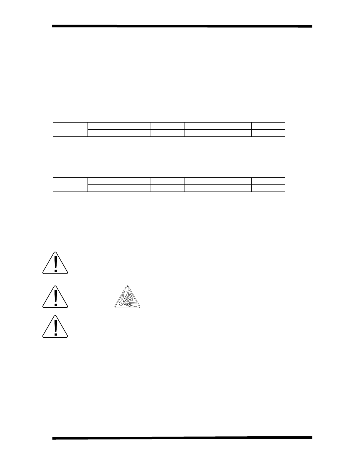
Hardwire type UPS units are not equipped with an over-current protection device nor an output
disconnect for the ac output. Therefore, a circuit breaker should be provided by the user between the
UPS output and the load input. This device should be rated as follows:
240VAC
RATING
The maximum ambient temperature in which the UPS unit should be operated in is 104° F (40° C).
The nominal battery voltages for these models are as follows:
BATTERY
VOLTAGE
Servicing of the batteries should only be performed by a qualified Toshiba Representative who is
knowledgeable of batteries and the required precautions. Keep unauthorized personnel away from
batteries. To arrange for battery replacement, contact your nearest Toshiba authorized service
center.
3.6kVA 6kVA 8kVA 10kVA 14kVA 18kVA
20A 30A 40A 60A 80A 125A
3.6kVA 6kVA 8kVA 10kVA 14kVA 18kVA
216Vdc 216Vdc 288Vdc 288Vdc 288Vdc 288Vdc
This manual contains important instructions
for 3.6, 6, 8, 10, 14, and 18 kVA that should
Misuse of this equipment could result in human injury and equipment
CAUTION
Do not dispose of the batteries in a fire. The batteries may explode.
CAUTION
Do not open or mutilate the batteries. Released electrolyte is harmful to
CAUTION
damage. In no event will Toshiba Corporation be responsible or liable for
either indirect or consequential damage or injury that may result from the
use of this equipment.
the eyes and skin and could also be toxic.
8
TOSHIBA
IMPORTANT SAFETY INSTRUCTIONS (cont'd)
DANGER
1) Verify that the UPS is off and that the power cord is disconnected from the power source.
2) Remove watches, rings or other metal objects.
3) Use tools with insulated handles to prevent inadvertent shorts.
4) Wear rubber gloves and boots.
5) Do not lay tools or metal parts on top of batteries.
6) Determine if the battery is inadvertently grounded. If inadvertently grounded, remove source
of ground.
The likelihood of such shock will be reduced if such grounds are removed during
installation and maintenance.
Contact with any part of a grounded battery can result in electrical shock.
A battery can present a risk of electrical shock and high short
circuit current.
Observe the following when working on batteries:
INSTRUCTIONS IMPORTANTES CONCERNANT
LA SÉCURITÉ
CONSERVER CES INSTRUCTIONS
Cette notice contient des instructions importantes concernant la sécurité.
Une battery peut présenter un risque de choc électrique, de brûlure par
ATTENTION
ATTENTION
transfert d' énergie.
L' élimination des batteries est règlementèe. Consulter les
codes locaux à cet effet.
9

TOSHIBA
Product Description
Theory of Operation
An uninterruptible power supply is a system that is installed between the commercial power
and the load equipment. The UPS provides steady ac output power during commercial power
short-term blackouts or brownouts. This power is provided for a long enough time so that the
load can be shut down in an orderly fashion. This prevents loss of data and possible damage to
both hardware and software.
During normal operation, the UPS uses commercial ac power. In addition, it takes in all of the
high voltage spikes and transients caused by switching and faults, and all of the commonmode and normal mode noise which is associated with commercial ac power. The UPS
converts it all to flat dc power. From this power, the UPS charges its batteries and
generates its own extremely high quality ac waveform output. The result of this process is
maximum power conditioning and regulation.
If the ac power supplied to the UPS drops below a specified voltage level, the unit's batteries
automatically begin supplying power instead of receiving it. This insures that the loads
connected to the UPS continue to receive power with no interruption. When ac input power
becomes available again, operation returns to normal. The unit's batteries begin to recharge
so they will be ready for the next power interruption.
Application and Use
Toshiba's 1600EP Series of on-line uninterruptible power supply (UPS) systems provide
continuous computer-grade ac power in a compact, high performance, and energy efficient
unit. The UPS unit assures safe and reliable operation of critical office equipment. This can
range from word processors and personal computers to mini-computers and local area
networks. All units feature an audible alarm which sounds if the battery voltage drops below
standard during use. This is an additional aid to help in retaining the valuable office data
banks. All units allow for computer interfacing.
Output Rating
Toshiba's 1600EP Series (208/240V) offers UPS models with the following capacities:
MODEL Output Capacity @ 240V Output KW @ .85PF 240V
UE3G2L036C61T 3.6KVA 3.1KW
UE3G2L060C61T 6KVA 5.1KW
UE3G2L080C61T 8KVA 6.8KW
UE3G2L100C61T 10KVA 8.5KW
UE3G2L140C61T 14KVA 11.9KW
UE3G2L180C61T 18KVA 15.3KW
Power Backup
When an electrical power failure occurs, the UPS’s internal batteries automatically supply backup power to the load without interruption. For example, when used to support a computer, the
UPS back-up assures enough additional time to complete the activity and store the data. This
allows an orderly shutdown after a power failure has occurred.
Power Conditioning
When commercial power is present, the UPS supplies conditioned power to the load while
maintaining its batteries in a charged condition. The UPS protects against the normal, everyday
problems associated with heavy use of raw commercial power, including power sags,
surges, signal interference, and spikes. This protection keeps power-line problems from
reaching your load, where they can cause equipment to operate erratically, or damage
software and hardware.
10

TOSHIBA
Inspection/Storage/Disposal
Inspection of the new UPS equipment
Upon receipt of the UPS, a careful inspection for shipping damage should be made.
After Uncrating:
1) Check the unit for loose, broken, bent or otherwise damaged parts. If damage has occurred
during shipment, keep all original crating and packing materials for return to shipping agent.
Warranty will not apply to units which are damaged during shipment.
2) Check to see that the rated capacity and the model number specified on the nameplate
conform to the order specifications.
Storage of UPS Equipment
If the UPS equipment is to be subject to long or short term storage the following guidelines
should be used.
Avoid:
1) Storage in sites subject to extreme changes in temperature or high humidity.
2) Storage in sites subject to exposure of high levels of dust or metal particles
3) Storage on inclined floor surfaces or in sites subject to excessive vibration.
Before Storing:
1) Allow UPS to be operated for 24 hrs. to ensure that the batteries are fully charged.
2) Stop the unit (see "Stopping the UPS" on page 41).
3) Place the unit's MCCB switch (see pages 45-46 for location) in the "off" position.
Storing:
1) Store within a temperature range of -20 ~ 40° C (-4 to 104° F).
2) For best results, store the UPS in the original shipping container and place on a wood or
metal pallet.
3) The optimum storage temperature is 21° C (70° F). Higher ambient temperatures
cause UPS batteries to need recharging more frequently.
After Storing:
1) If stored in an ambient temperature under 20° C (68° F), recharge the batteries every 9
months.
2) If stored in an ambient temperature of 20° to 30° C (68° to 86° F), recharge the batteries
every 6 months.
3) If stored in an ambient temperature of 30° to 40° C (86° to 104° F), recharge the batteries
every 3 months.
Disposal
Please contact your state environmental agency for details on disposal of electrical
components and packaging in your particular area.
It is illegal to dump lead-acid batteries in landfills or dispose of improperly.
Please help our Earth by contacting the environmental protection agencies in your area, the battery
manufacturer, or call Toshiba toll-free at (800) 231-1412 for more information about recycling.
11
TOSHIBA
Precautions
Installation Precautions
1) Install the unit in a well-ventilated location; allow at least 10 cm (4 inches) on all sides
for air ventilation and for maintenance.
2) Install the unit in a stable, level, and upright position which is free of vibration.
3) Install the unit where the ambient temperature is within the correct operating range
(see UPS Specifications pages 18 - 21).
4) Do not install the UPS in areas that are subject to high humidity.
5) Do not allow direct sunlight to shine on the unit.
6) Do not install the UPS in areas which are subject to contamination such as high levels
of airborne dust, metal particles, or inflammable gas.
7) Avoid installation near sources of electrical noise, and always make sure that the unit earth
ground is intact to prevent electrical shock and to help reduce electrical noise.
8) Do not install where water or any foreign object may get inside the UPS.
9) This UPS generates and can radiate radio-frequency energy during operation. Although RFI
noise filters are installed inside the unit there is no guarantee that the UPS will not influence
some sensitive devices which are operating close by. If such interference is experienced,
the UPS should be installed farther away from the affected equipment and/or powered from
a different source than that of the affected equipment.
CAUTION
10) User should provide output over current protection for hardwired UPS versions.
See Safety Instructions on page 8 for the correct device rating.
CAUTION
Operating Precautions
1) The UPS should not be powered up until the entire operation manual has been reviewed.
2) The input power source voltage must be within +10% to -30% of the rated input voltage. The
input frequency must be within the rated input frequency range. Voltages and frequencies
outside of the permissible tolerance range may cause internal protection devices to activate.
3) The UPS should not be used with a load whose rated input is greater than the rated UPS output.
4) Do not use the UPS to provide power to motors that require high starting current or a long
starting time such as vacuum cleaners and machine tools (over sizing for lock rotor current
required).
5) Do not insert metal objects or combustible materials in the unit's ventilation slots.
6) Do not place, hang, or paste any objects on the top or on the exterior surfaces of the UPS.
12
UPS Connections
Terminal Block
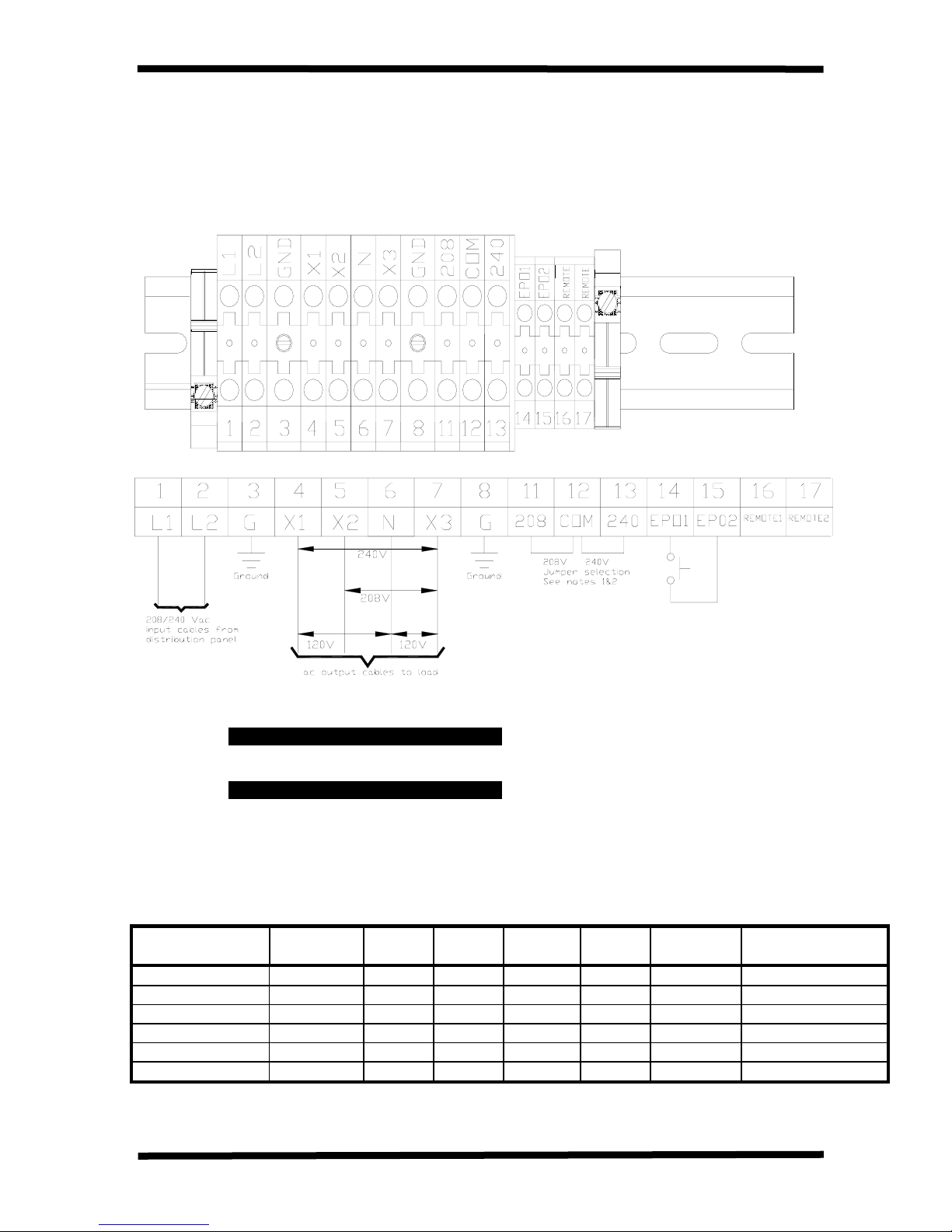
The following illustration is a detail view of the terminal block and wiring connections used
for 208/240 volt units (see pages 45-46 for terminal block location).
TOSHIBA
Notes: 1) If ac input power is 240Vac rated, terminals 12 and 13 must be shorted by jumper wire
Do not jumper terminal 11 to 12 or 13.
2) If ac input power is 208Vac rated, terminals 11 and 12 must be shorted by jumper wire
Do not jumper terminal 13 to 12 or 11. Factory Setting is 208Vac.
Wire Size and Tightening Torque
Use the following table to select the recommended wire size and terminal lug tightening torque
for I/O wire connections. Note: The bold number in () is the maximum size wire that the
terminal block can accomdate.
Item Terminal
Number
AC input lines 1 and 2 (8) 12 (8) 10 (1/0) 8 (1/0) 6 (1/0) 4 14.2
AC output lines 4, 5, and 7 (8) 12 (8) 10 (1/0) 8 (1/0) 6 (1/0) 4 14.2
AC output neutral 6 (8) 12 (8) 10 (1/0) 8 (1/0) 6 (1/0) 4 14.2
Ground 3 and 8 (8) 12 (8) 10 (1/0) 8 (1/0) 4 (1/0) 4 14.2
EPO switch 14 and 15 16 16 16 16 16 9.0
Remote Switch 16 and 17 16 16 16 16 16 9.0
AWG
3.6kVA
AWG
6kVA
AWG
8kVA
AWG
10kVA
(1 Newton-meter = 8.8 pound-inches)
AWG
14-18kVA
Tightening Torque
(Pounds-Inches)
13
UPS Connections
Communication Interfaces
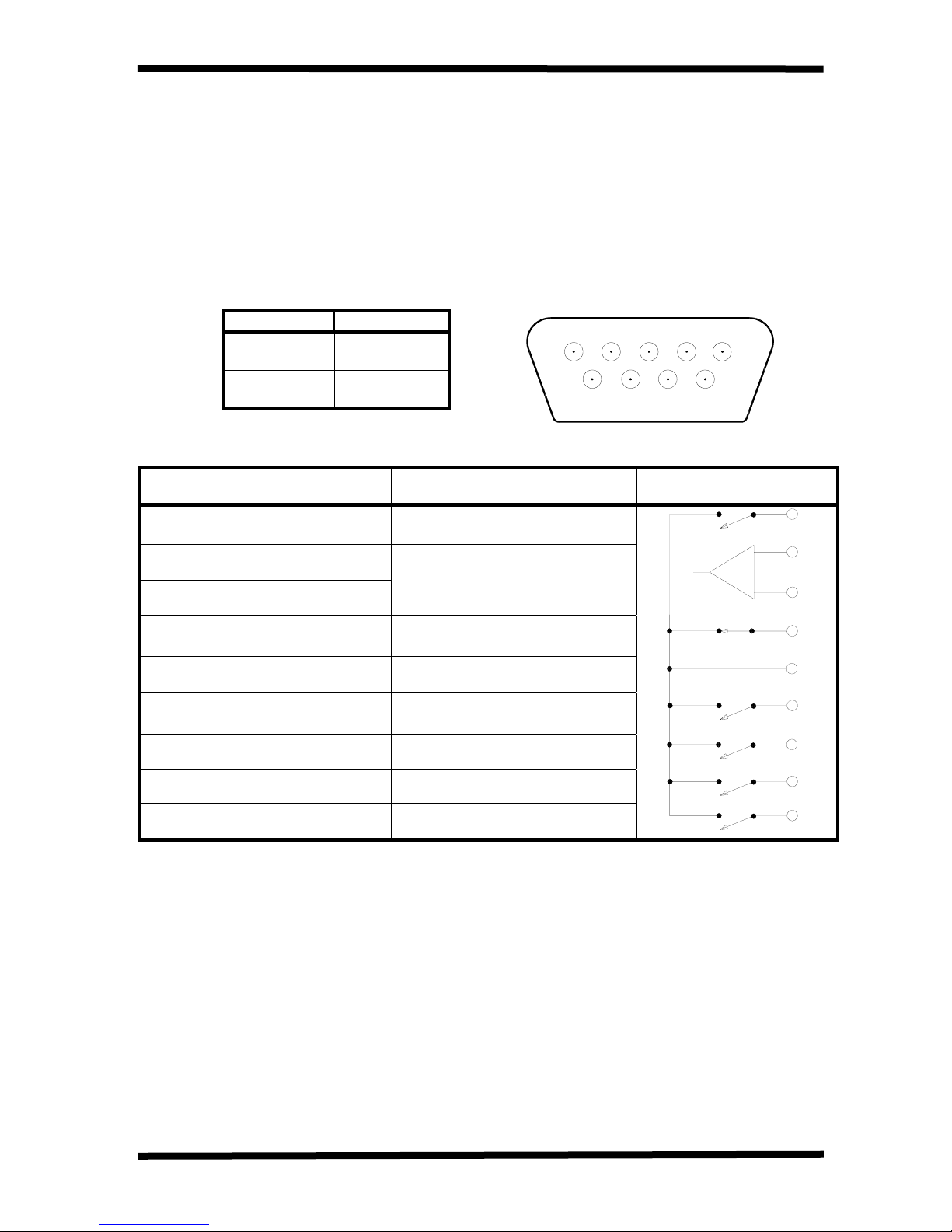
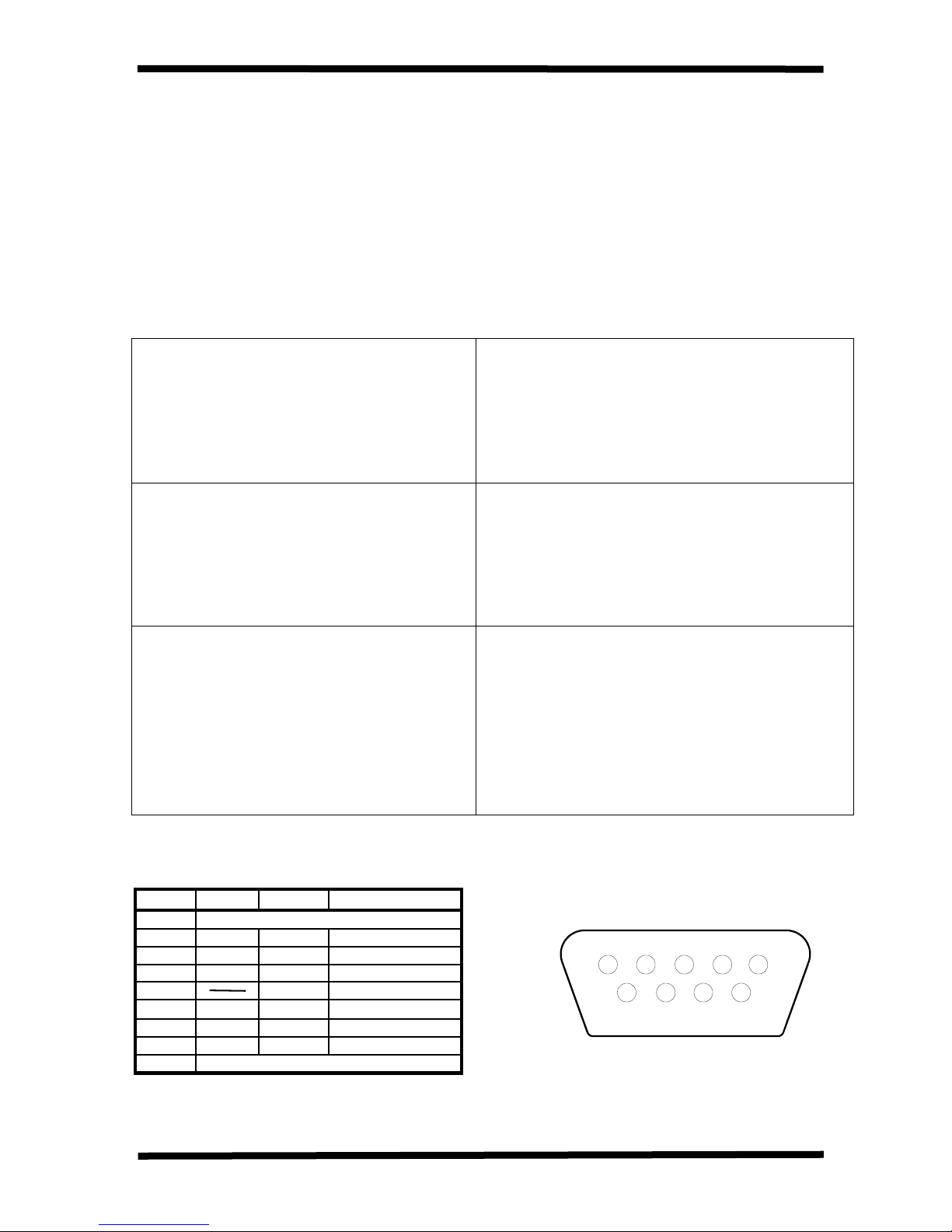
Remote Contacts
The remote interface is a standard feature and is available as solid state relay switch
Contacts through a DB9 male connector located on the back side of the UPS (see pages 4546 for DB9 connector location). The following chart shows the solid-state relay pin
assignment’s for each signal and the associated DB9 connector pinout.
TOSHIBA
Maximum current carrying
capacity of the switch
Voltage Current
48Vdc Peak 100mAdc
peak
30Vac rms
(42Vac peak)
Pin
1 Fault Signal Closed when fault detected
2 UPS stop common
3 UPS stop signal input
4 Normal input power supply Closed with normal supply power
5 Signal common Common signal return
6 Bypass operation Closed during bypass operation
Signal Function
70mAac rms
(100mA peak)
Logic In the UPS
Backup stop when the level
changes from Low (-3 to – 15V)
to High (+3 – +15V)
DB9 Male Connector Outline
(facing connector)
1 2 3 4 5
6 7 8 9
1
2
3
4
5
6
7 Battery voltage drop Closed at voltage drop
8 UPS operation Closed during inverter operation
9 Power failure signal Closed at power failure
Notes:
1) Pin "switches" are shown in their inactive states. If battery voltage is low, pin 7 will
be connected to pin 5.
14
7
8
9
TOSHIBA
UPS Connections
Communication Interface (cont'd)
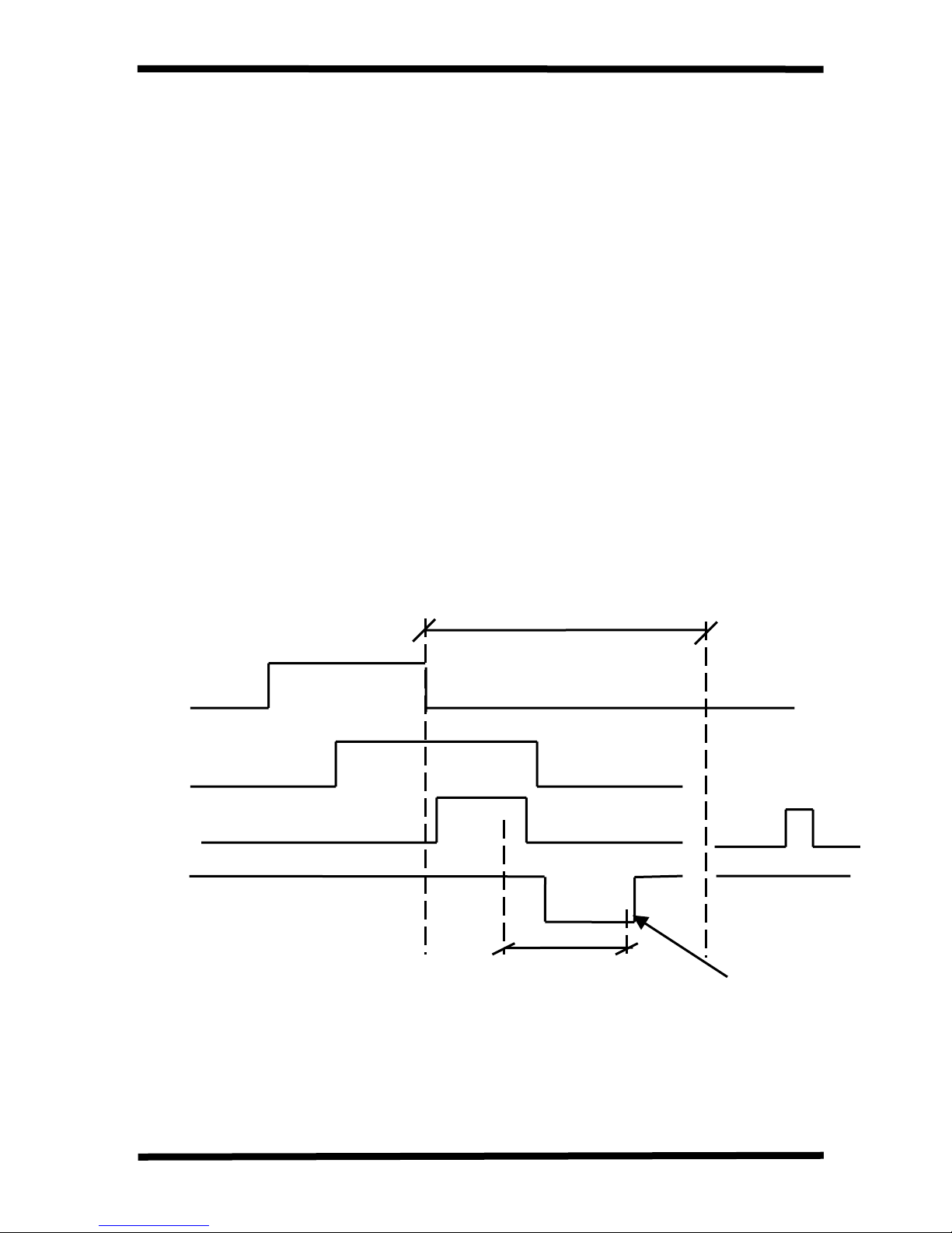
UPS Stop Signal Operation
When the UPS stop signal is sent to the UPS through pin 2 and 3 of the external contact
interface, it is possible to automatically reset the following operating systems (OS), which
can automatically implement the shutdown function and restart the operation:
Applicable OS: Windows NT, IBM OS/2 LAN server, LANtastic
When the power fails, the OS detects the power failure signal from the UPS and starts the
shutdown process.
At the end of the shutdown process, the OS outputs a stop signal to the UPS, and the UPS stops.
When the power recovers, the UPS automatically starts output and restarts the OS. Even
when the power recovers while in a shutdown process, the UPS temporarily cuts off the
output (10 - 20 seconds) and then restarts the OS within 10 minutes after the recovery from
power failure. In this case the UPS cuts off output even with normal input power. Connect
the UPS stop signal of the external contact interface only for the automatic processing so
that the UPS output will not be cut off by mistake. If a stop signal is sent to the UPS ten
minutes or more after the recovery from a power failure, then the UPS ignores this signal
and continues to output power.
If the computer is started/restarted within 10 minutes after the recovery from a power
failure, the power supply may be reset while the computer is restarting.
10 minutes
power failure
normal
UPS stop signal from OS
UPS output voltage
backup
OS shutdown
continues output
Checking time
Temporarily cuts off the
output for 10 to 20 secs.
15
UPS Connections
Communication Interfaces (Cont'd)
RS-232C
The RS-232C serial communication interface is available through a DB9 female connector
located on the back side of the UPS (see pages 45-46 for DB9 connector location). This
interface allows control of the UPS from a personal computer running special Toshiba
software. The computer and the UPS are connected through a serial RS-232C
communication port. The available data from the UPS, via the RS-232C communication link,
is shown below:
Operating Conditions
TOSHIBA
Input voltage
Output voltage
Output current
Battery voltage
Input frequency
Output frequency
Utility power OK
Low battery voltage detected
UPS operating status
(described as ‘yes’ or ‘no’)
UPS in BYPASS mode
UPS in NORMAL mode
Input and output frequency synchronized
UPS ‘Fault’ occurred
DC bus overcurrent
DC bus overvoltage
DC bus undervoltage
‘Fault’ details
(described as ‘occurred’ or ‘not occurred’)
Input overcurrent
Overheat
Overload being timed
Overload (allowable time exceeded)
Output overvoltage (during NORMAL mode)
Output undervoltage (during NORMAL mode)
The connector pin assignment and female connector outline are illustrated below.
RS-232C Connector Pin Assignment
Pin I/O Symbol Description
1 This pin is not used
2 Input RXD Receive data
3 Output TXD Transmit data
4 Output DTR Data terminal ready
5 SG Signal ground
6 Input DSR Data set ready
7 Output RTS Request to send
8 Input CTS Clear to send
9 This pin is not used
DB9 Female Connector Outline
(facing connector)
5 4 3 2 1
9 8 7 6
16
UPS Connections
Communication Interfaces (Cont'd)
RS-232C Interface Communication Specifications
The RS-232C serial communication specifications are shown below:
TOSHIBA
1) Communication system
2) Connection control system
3) Transmission speed
4) Synchronization method
5) Transmission code
6) Error detection
7) Error correction
8) Response monitoring
9) Transmission character format
10) Bit sending order
11) Frame length (information message)
Half-duplex communication system (serial
transmission)
Centralized control, polling/selecting system
1200/2400/4800/9600 baud
Start-stop synchronization
JIS X 0201,7bits (ANSI)
Vertical parity check, even (VRC)
longitudinal parity check, even (LRC)
None
None
10 bits
Low-order bits first
Variable length
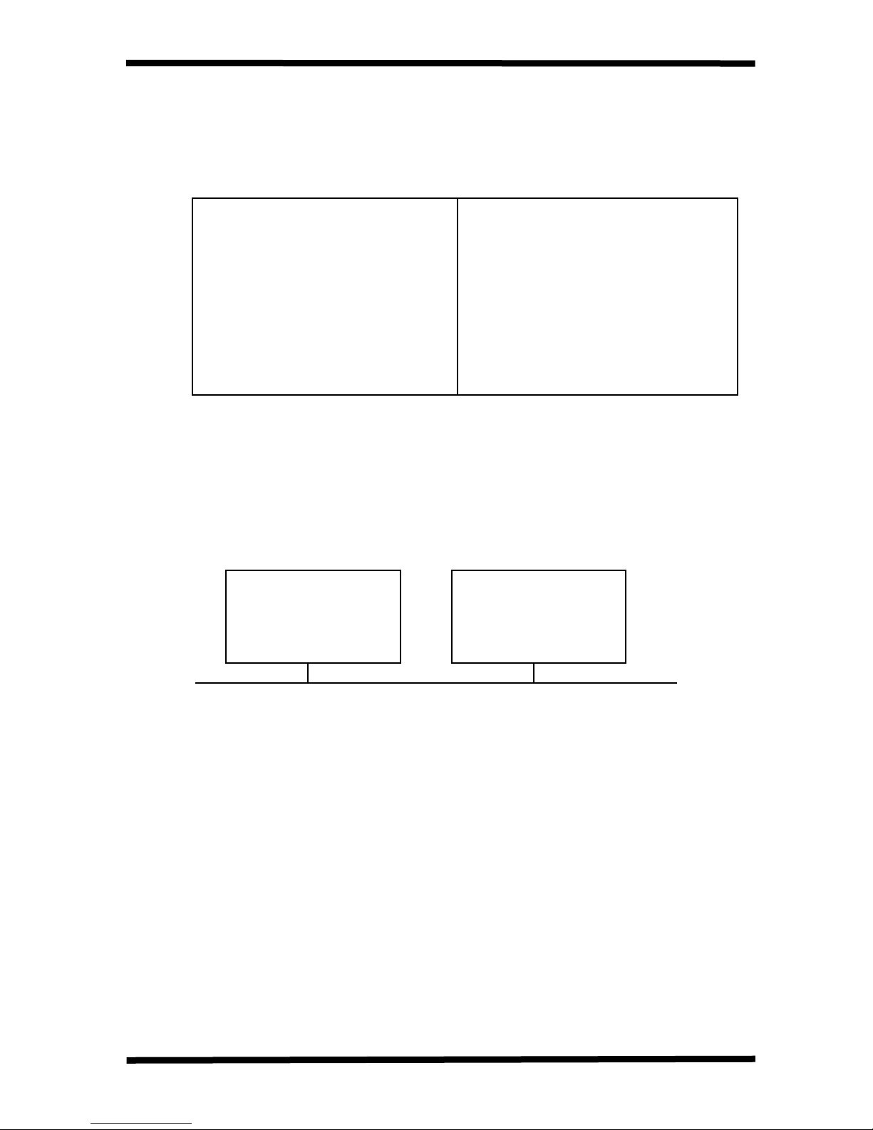
RemotEye Network Card
The RemotEye is an optional network card for Toshiba UPS. This card slides into a slot located on
the back side (pages 45-46) of the UPS. The card provides a network, or LAN-based
communication interface for the UPS. When installed, the UPS can be managed remotely using the
common SNMP and HTTP (web-based) network protocols. The following diagram shows the flow of
the Network Management Station.
Network
Management
Toshiba UPS
Station
Network Communication through Ethernet
Note:
The UPS communication mode setting must be set to “SNMP” mode when using the RemotEye
network card (See Comm Mode variable in the 'Data Setting Screens' on page 32 and 34).
17
 Loading...