

PRODUCT GUIDE
Microcomputer
2006-10
http://www.semicon.toshiba.co.jp/eng
02 03
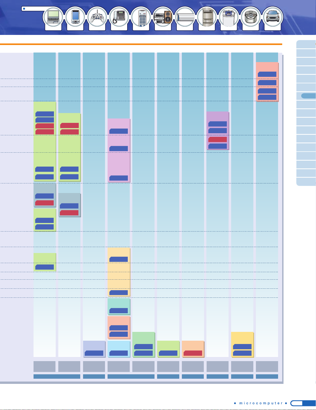
Toshiba microcomputer line-up
Toshiba softwear IP line-up
TX49 Family
FamilyTLCS-900
Toshiba microcomputer development system product line-up
Toshiba offers total solutions to meet your microcomputer needs with an extensive
product line-up supported by our software and development system experts.
64-pin QFP
14mm
14mm / 0.8mm pitch
64-pin LQFP
10mm
10mm / 0.5mm pitch
TLCS-900/H Series
TLCS-900/L
Series
TLCS-900
Series
TLCS-900/L1 Series
TX49/H2 Series
TX49/L4 Series
TX49/L3 Series
TX49/H3 Series
TX49/H4 Series
TX49/W4 Series
TX99 Family
TX99/H4 Series
TLCS-900/H1 Series
High-Speed
TLCS-900/H1 Series
16-bit 32-bit
32-bit
32-bit
64-bit
64-bit
8-bit
Portable devices
Digital information appliances (broadband/OA equipment)
Digital consumer (DSC/DVC/DVD/DTV/STB)
Automotive equipment
Automotive equipment
Audio
TV/communications (cordless phones)/electric appliances/inverter appliances
TX19A Series
TX19 Series
TX19 Family
TX39 Series
MeP
TX39 Family
Performance
TLCS-47 Family
TLCS-870/C Series
Toshiba Integrated
Development Environment
(TIDE)
TLCS-870 Series
RTE47 model 10 system
RTE47 system
RTE870 model 10 system
TLCS-870/X Series
TLCS-870/C1 Series
TLCS-900 Family
TX19 Series
TX19A Series
RTE870/X model 25 system
RTE870/X model 15 system
RTE870/C model 15 system
RTE870/C Light system
RTE900 model 25 system
RTE900 model 15 system
DSU PROBE for N-WIRE
DSU PROBE model 120
DSU PROBE model 110
In-circuit emulator
On-chip debug emulator
NEW
Real-Time OS
Real-Time OS
Real-Time OS
8
-bit
TLCS-870 Family
TLCS-870/X
TLCS-870/C
TLCS-870
TLCS-870/C1
NEW
Core architecture optimized
for C compiler
Minimum instruction execution time: 250 ns
Minimum instruction execution time: 125 ns
Address space extended to 1 Mbyte
■
High-speed processing capability equivalent
to 16-bit microcontrollers
■
Address space extended to 128 Kbytes
■
5-V operation
■
On-chip debug function
[New Core] TLCS-870/C1 Series
The new 8-bit CPU core delivering high-speed processing capability
and memory address space extension, while offering instruction code
compatibility with TLCS-870/C
Under development
TMP89FS60UG/FG
NEW
General-purpose 64-pin product providing various interfaces for serial
communications and a timer system
TCP/IP protocol stack
HTTP server
JPEG
IrDA protocol stack
USB1.1 (device)
Embedded file system
Authentication Library
CompactFlash Driver
SD Memory Card Driver
Library
Handwritten Recognition
Interface
Graphics
Graphical
Speech Codec
Text to Speech (TTS)
TLCS-870 FamilyLL Microcontroller
TLCS-47E Series
T4X Series
T6H Series
TLCS-870/X Series
TLCS-870/C Series
TLCS-870 Series
TLCS-870/C1
Series
TLCS-47 Family
LL Microcontroller
4-bit
Remote controls/calcurators/digital clocks/portable game machines
NEW
04 05
Product line-up
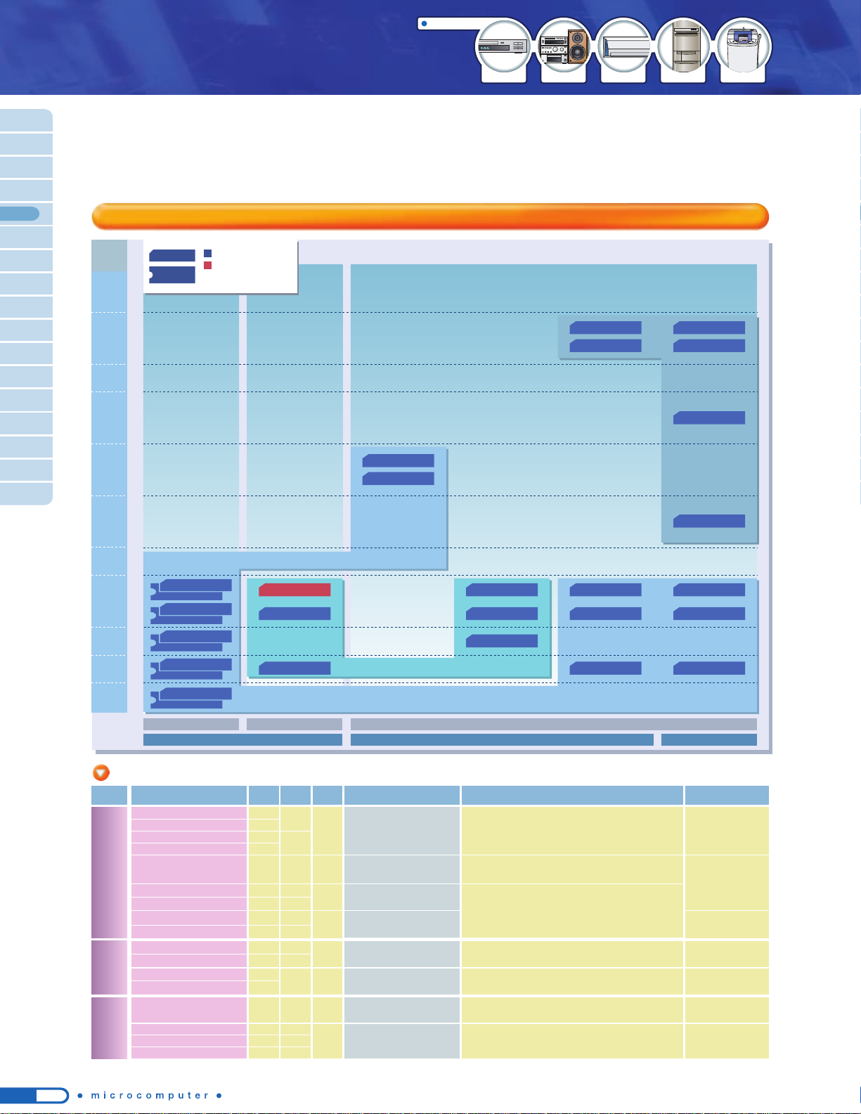
Toshiba has newly developed TLCS-870/C1 Series of 8-bit microcontrollers that deliver high-speed processing capability equivalent to 16-bit
microcontrollers. The TLCS-870/C1 Series achieves high-speed processing capability at low internal clock frequencies by operating one instruction
cycle in a single clock cycle. Toshiba's proprietary memory segment method allows addressing up to 128 Kbytes of memory address space.
16-bit
8-bit
32-bit
32-bit
8-bit Flash microcontrollers based on TLCS-870/C1 core
The new 8-bit CPU core delivering high-speed processing capability and memory address space extension, while offering instruction code compatibility with TLCS-870/C
NEW
NEW
8-Bit Microcontrollers
TLCS-870/X
TLCS-870/C
TLCS-870
TLCS-870/C1
TLCS-900/L1
TLCS-900/H1
High-Speed
TLCS-900/H1
NEW
Performance
Low power consumption
Low noise
Core architecture optimized
for C compiler
Minimum instruction execution
time: 250 ns
Minimum instruction execution time: 125 ns
Minimum instruction execution time: 111 ns
Minimum instruction execution
time: 125 ns
Minimum instruction execution
time: 50 ns
Address space extended to 1 Mbyte
8-bit microcontrollers
16-bit 32-bit8-bit
TMP89FS60UG/FG
✽✽
General-purpose 64-pin product providing various interfaces for serial communications and a timer system
Flash version or mask version can be selected.
16KB
42-pin 44-pin 48-pin 64-pin 80-pin 100-pin
32KB
60KB
96KB
ROM
L
LCD driver built-inStandard product
LLL
LL
L
870/C1 Series road map
(planned)
✽✽
: Under development
++
: Under planning
Part Number
TMP89CM60UG/FG
++
TMP89CS60UG/FG
++
TMP89FS60UG/FG
✽✽
ROM
32 KB
60 KB
60 KB
RAM
3.0 KB
3.0 KB
3.0 KB
8KB
16KB
32KB
64KB
96KB
128KB
Program size (data + code)
1
1
2 3 4
Accessible to the address
space (128 Kbytes)
doubled over 870/C by
the segment method
TLCS-870/C1 Series: Minimum instruction execution time of 125 ns
TLCS-870/C Series: Minimum instruction execution time of 250 ns
*The minimum instruction execution time is reduced by half compared to TLCS-870/C.
Advantages of low-frequency operation
TLCS-870/C Series
64 Kbytes (data + code)
TLCS-900/L1 Series
TLCS-870/C1 Series
128 Kbytes (Max)
Code: 64 Kbytes
Data: 64 Kbytes
Segment method
New
High-speed processing at a low clock frequency
Toshiba's proprietary memory management method (segment method)
Address space extendable to 128 Kbytes
One instruction cycle operated in a single clock cycle
Toshiba's proprietary memory segment method manages
instruction codes and data independently in separate memory
address spaces. This new method enables memory address space
extension without affecting processing speed or code efficiency for
small- to large-sized programs exceeding 64 Kbytes.
The core architecture is configured to reduce the number of clock
cycles required to complete one machine cycle to a single clock
cycle. This achieves processing performance four times that of
TLCS-870/C Series at the same internal clock frequency.
Features of TLCS-870/C1 Series
Toshiba Integrated Development Environment (TIDE)
Emulators
Development System
Toshiba microcontroller core line-up
C Compiler
Assembler
Build Manager
Debugger
Linker
Framework
Editor
*Under development. Specifications are subject to change without notice.
On-chip debug emulator In-circuit emulator
Toshiba Microcontrollers TLCS-870/C1 Series
Realizing processing capability equivalent to 16-bit microcontrollers and
memory address space extendable up to 128 Kbytes
Suitable for high-performance
and multifunctional home
appliances, audio equipment
and portable devices
TLCS-900 Family
8-bit microcontrollers
High-speed processing capability
equivalent to 16-bit microcontrollers
Address space extended to 128 Kbytes
5-V operation
On-chip debug function
TLCS-870 Family
Suitable for home appliances
TLCS-870/C1 Core
Operating voltage: 4.5 to 5.5 V at 8 MHz, 2.7 to 5.5 V at 4.2 MHz
Clock gear:
1/4, 1/2, 1/1
Built-In Functions
Voltage detecting circuit
(Two voltage levels detectable, reset or interrupt selectable)
Power-on reset circuit
(Threshold voltage: 2.4 V
0.2 V)
8-bit timer/counter: 4 channels
(Resolution: 125 ns at 8 MHz)
16-bit timer/counter: 2 channels
(Resolution: 250 ns at 8 MHz)
UART/SIO*: 2 channels
(UART: 128 Kbps, SIO: 4 Mbps at 8 MHz)
UART: 1 channel
(UART: 128 Kbps at 8 MHz)
I
2
C/SIO*: 1 channel
(I
2
C: 400 Kbps, SIO: 4 Mbps at 8 MHz)
*
Two SIO channels can be used simultaneously.
10-bit AD converter: 16 channels
Built-in pull-up resistors
On-chip debug function (Flash version only)
8 MHz
Analog
input
TXD/RXD
SCLK/SI/
SO
SDA/SCL/
SCLK/SI/
SO
TXD/RXD
32 kHz
Pulse output
Timer/counter
input
Pulse output
Timer/counter
input
Interrupt
I/O port
POR/
VLTD
ROM
10-bit
AD
(16ch)
UART/
SIO
(2ch)
I
2
C/
SIO
(1ch)
UART
(1ch)
RAM
870/C1
Core
8-bit
timer
(4ch)
16-bit
timer
(2ch)
I/O
56
Packages:
UG: 64-pin LQFP (10 mm x 10 mm/0.50-mm pitch)
FG: 64-pin QFP (14 mm x 14 mm/0.80-mm pitch)
Internal clock
TLCS-870/C
Series
TLCS-870/C1
Series
One machine cycle
One machine cycle
◆
Compared to the TLCS-870/C, power consumption can be reduced at the
same performance level.
◆
Noise generation can be reduced.
At higher frequencies...
Low-frequency
operation
(8 MHz)
(16 MHz 24 MHz 32 MHz)
Code and data in the same area
64-Kbyte code
segment
64-Kbyte data
segment
Code
Data
Code
Additional code
Data
Code: Instruction op-codes and operands
Data: Sources and destinations of load and arithmetic instructions, etc.
Conventional 8-bit product
Segment method
Software design facilitated
Compact core and object sizes
Compared to the address bus
extension method, core and code
sizes are reduced. The instruction
set is compatible with TLCS870/C.
Unlike the bank switching method, small- to
large-sized programs need not be modified.
Processing speed and code efficiency are
unaffected even if the code size exceeds 64
Kbytes.
Using the Integrated Development Environment (IDE) together with C
Compiler enables seamless operations of coding, building and debugging
tasks which must be performed repeatedly in the software development
process. Toshiba development tools offer a variety of latest functions to
realize a user-friendly and highly efficient debug environment.
*The target system requires a separate power supply.
*The target system requires a separate power supply.
Target
system
Host
system
USB
Control
interface
cable
RTE870/C1
on-chip
debug
emulator
Target
system
Host
system
USB
MCU
probe
RTE870/C1
emulator
Business-card-sized compact emulator
No need for power supply (using USB bus power)
Target connection via a narrow-pitched cable
Extensive on-chip debug functions
Break/event : 8 breakpoints/1 event
Trace :
The last two branches
can be stored in real time.
Memory access: Display/Rewrite during
program execution in 1-byte units
(with a wait of 1 clock cycle)
Debug pin : Two I/O pins
Flash programming function
IDE included
(downloadable from website)
Compact, low-cost, yet highly functional in-circuit emulator
(compared to RTE870/C model 15)
Various 870/C1 Series devices supported by replacing the probe
Common probe with RTE870/C Light*
(*) Compact emulator for 870/C Series
Connected with the host system via USB
IDE included (downloadable from website)
Supports on-chip debug emulation.
06 07
Toshiba’s Flash Microcontrollers
16-bit
4 KB
28/30/32 42/44/48 64 80 100 144 177/193
FBGA
281
FBGA
8 KB
16 KB
32 KB
48 KB
64/60
KB
96 KB
128/120
KB
256 KB
384 KB
512 KB
1 MB
2 MB
Capacity
Under development
Under development
Pin count
Under planning
Under planning
Under development
Under planning
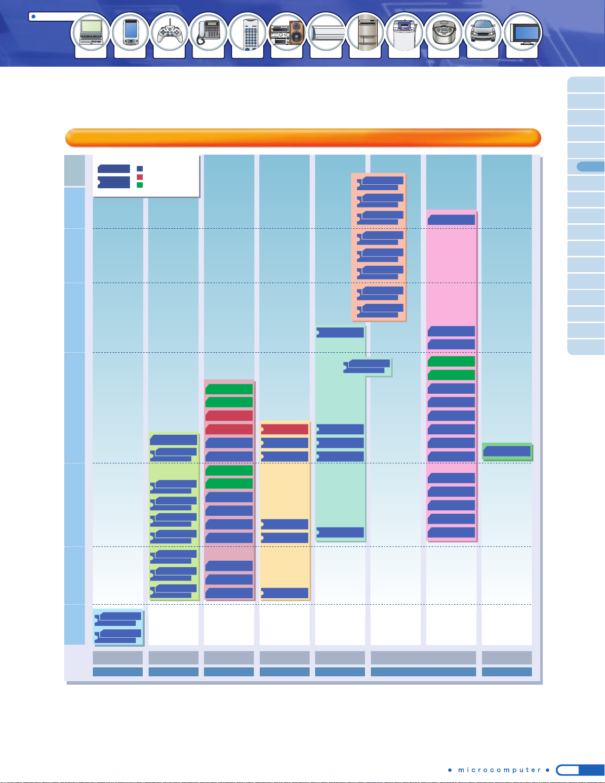
Products with built-in LCD driver
Features of Toshiba’s Flash microcontrollers
Full support system for Toshiba’s Flash microcontrollers
Products in low-pin-count packages
8-bit
TMP86FM23++
TMP86FP24
TMP86FM25
TMP86FM26
TMP86FS27
TMP86FM28++
TMP86FM29
TMP91FW40
TLCS-870 Family
8-bit
TMP86F409
TMP86F807
TMP86F808
TMP86F809
TMP86F892++
TMP86FH09
TMP86FH12
TMP86FH46A
TMP86FM46++
TMP86FH47A
TMP86FM47++
TMP86FH92
TMP86FH92I
TMP86FH93
TLCS-870 Family
TLCS-900 Family
High-speed programming
NANO FLASHTM allows 0.5 Mbytes of data to be programmed in 2 seconds.
Flash programming service
Various programming tools
Toshiba offers a wide variety of programming tools to meet various needs of customers from
development to mass production. Programming services are also available.
Toshiba Semiconductor website
8-bit microcontroller
TMP89FS60
General-purpose 64-pin product providing various interfaces for
serial communications and a timer system
16-bit microcontroller
TMP91FY42
100-pin product featuring large-capacity Flash memory (256 Kbytes)
32-bit microcontroller
TMP92FD28
100-pin product incorporating a USB host controller
Enhanced security function
Up to 255 bytes of password protection can be implemented to
prevent illegal read accesses.
A wide range of operating voltages
Operating voltages ranging from 2.7 V to 5 V are supported.
Various Flash programming methods
In addition to serial mode and parallel mode, ISP (In System
Programming) is supported.
Low power consumption
NANO FLASHTM realizes the same level of low power
consumption compared with mask ROM products.
Quick programming service
Flash programming service is available to enable QTAT
(quick turnaround time).
On-chip debug function incorporated
The on-chip debug function improves development efficiency by
allowing debugging on mass-production boards.
Toshiba’s Flash programming tool
Flash adapter
Connection example
The Flash adapter is a programming adapter
supporting Toshiba’s microcontrollers with onchip Flash memory. Connecting the Flash
adapter with your PC allows you to program,
erase and verify on-chip Flash memory. The
Flash adapter is provided for each package type.
Category
Off-board
programming
(Note 1)
On-board
programming
(Note 2)
Programming services
(Note 4)
Tool type
Programming adapter
Note 1: Off-board programming is a method to program a Flash device before it is mounted on the system board.
Note 2: On-board programming is a method to program a Flash device after it has been mounted on the system board.
Note 3: The in-circuit programmer from Flash Support Group allows off-board single-device programming by connecting an optional adapter.
Note 4:
Programming services are also available from some of the other programming tool vendors in this table apart from Toshiba and MICROTEK.
Note 5:
Some limitations apply when the programming adapter is used for mass production. For details, contact your local Toshiba sales representative.
: Supported
Toshiba Corporation
Toshiba Corporation
MICROTEK Inc.
Flash Support Group, Inc.
HI-LO System Research Co., Ltd.
MINATO ELECTRONICS INC.
Shanghai Gengyan Electric Technology Co., Ltd
T.S ELECTRONICS CO., LTD
Flash Support Group, Inc.
HI-LO System Research Co., Ltd.
MINATO ELECTRONICS INC.
Shanghai Gengyan Electric Technology Co., Ltd
Sophia Systems Co., Ltd.
Flash Support Group, Inc.
(Note 3)
Yokogawa Digital Computer Corporation
Single-device
programmer
Gang programmer
In-circuit programmer
Tool vendor
Development
Mass production
Maintenance
Phase
(Note 5)
Toshiba offers an extensive line-up of microcontrollers with on-chip Flash memory ranging from small-capacity
to 2 Mbytes. You can find a wide variety of products from low-pin-count devices to high-functionality devices.
NEW
* The user is required to connect write signals
and mount oscillators as appropriate to each
device.
A wide variety of peripheral functions
The line-up includes products with various application-specific functions,
such as an LCD driver, an inverter motor control function (PMD), or an
IGBT control timer, as well as general-purpose products.
QTAT
Manufacturing
process
Masked
ROM
product
Flash
product
Programming
order
QTAT is achieved by programming
the Flash microcontroller at Toshiba.
(Note)
Delivery
Delivery
Mask/ES creation process
ES
evaluation
Development
Development
Flash
programing
Customer
Mask/ES
order
Customer
Customer
Mass
production
order
●QTAT
........................
Quick Flash programming service is available.
(Note)
●Quality assurance..The same level of quality as that of
mask ROM products is assured.
●Marking
...................
Custom marking is possible.
●Support
...................
In addition to programming at Toshiba,
customers can use our partner programming
houses.
Note:
Delivery time varies with various conditions such as quantity, order acceptance time,
factory operation schedule, and product type. For details, please contact your local
Toshiba sales representative.
Flash programming service enables QTAT (quick turnaround time),
allowing customers to achieve shorter time-to-market.
TMP86F409
TMP86F807
TMP86F808
TMP86F809
TMP86F892
TMP89FS60
16-bit
TX19 Family
NEW
TMP86FM46
TMP86FM47
TMP91FW40
TMP91FW60
TMP86FS64
TMP88FW44
TMP92FD23A
TMP1940
TMP1942
TMP1942
TMP19A43
TMP19A43
TMP1962
TMP19A64
TMP92FD28
TMP92FD54AI
TMP91FY42
TMP92FY60
TMP19A71
TMP86FH09
TMP86FH12
TMP86FH46A
TMP86FH47A
TMP86FH92
TMP86FH92I
TMP86FM23
TMP86FM25
TMP86FM26
TMP86FM29
TMP86FM48
TMP86FM49
TMP86FH93
TMP86FS23
TMP86FS49A
TMP86FS49AI
TMP86FM28
TMP86FP24
TMP86FS27
TMP86FS28
TMP91FU62
TMP88FW45TMP91FW27
8-bit
32-bit
TLCS-900 Family
TLCS-870 Family
TX19 Family
TLCS-900 Family
TLCS-870 Family
http://www.semicon.toshiba.co.jp/eng/index.html
Information on the entire spectrum of Toshiba
semiconductor products is avaiable here.
●Solution
You can access latest information
for each of system applications.
●Product information
You can access a wide range of new-product information,
presentation data material and other data.
Under development
08 09
Toshiba offers a complete lineup of reliable, user-friendly development tools to support customers in each phase of
program development from design to evaluation.
Reliable, User-Friendly Development Systems for Toshiba Microcomputers
Toshiba Software IP
System Support
* The outlines of microcomputer development systems can be found on page 53 onward.
Compact ICE for TLCS-870/C Series
* For details of software IPs, see the page 61 of this product guide.
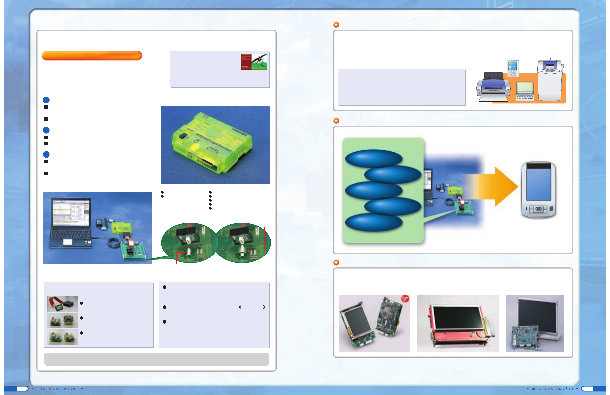
RTE870/C Light emulator
The RTE870/C Light emulator is comprised of the minimum
functions required for debugging, and comes in three types to
support all MCUs in the TLCS-870/C Series (excluding the
TMP86xx24FG).
The price is "Light".
Integration of the RTE controller and pod system makes
the emulator more affordable.
Comes with a free debugger download.
The connection is "Light".
The host interface is through USB.
Can be easily connected to a notebook PC.
The size is "Light".
A new system configuration succeeded in integrating
the system on a single board.
A smaller probe tip takes less space on the target
board.
Product components:
RTE870/C Light emulator
AC power adapter
Other required items:
Probe set
Emulation chip
Language tool
Host system (PC)
USB cable (USB standard A to B)
Target system
Host system
The probe set and options are manufactured by ADLINKS Co., Ltd. These products are distributed by Daimaru Kogyo K.K.
http://www.adlinks.co.jp/
[Usage example]
Exchange connector
Target connector
*The target system requires a separate power supply.
As product development becomes sophisticated and increasingly offers technical advantages, high-performance and
large-scale development becomes required in software development, and the development cycle has turned longer.
To address this situation, Toshiba aims to faster time to market, realize functions with software, and improve quality
by producing software components.
Toshiba’s MCU Plus Software IP Platform
Features of the Software IP
1. Full supports for microcomputers from 8 to 32 bits.
2. Optimized design concept for Toshiba microcomputers.
3. Pursuit of flexible designs and interfaces not limiting
application types.
4. Flexible response to any development environments
and platforms.
Option
Evaluation board for software IP (SWIP)
Reference model for LCD TV
Evaluation board for portable devices
TOP
Bottom
●
Software IPs ● Reference application software ● Reference models
We offer a v ariety of software and solution to speed up your development time.
Stacking connector
The stacking connector is used between the probe and the target
connector to raise height so that the target system can be connected
easily when there is not enough space around the target connector.
MCU mounting adapter for RTE870/C Light Bump socket
The bump socket is used together with the target connector to mount
an MCU on the target system.
M15-Light connection exchange cable
The M15-Light connection exchange cable allows you to connect the
RTE870/C Light system to a target system that has been debugged
with the RTE870/C model 15 system. (The target connecting board
used with the RTE870/C model 15 system is required.)
Probe set
The probe set is available f or each package pin count
or package type of supported MCUs.
Set components:
RTE870/C Light probe
Used to connect the emulator and target
system.
Target connector
Used to connect the probe to the target
system.
Exchange connector
Required with some MCUs.
* For the detailed specifications of the RTE870/C Light emulator, see
“Outline of TLCS-870 Family Development System on page 58.
Operation check and evaluation with a demonstration
board and application.
Software IP group
Network
File system
Speech recording
and playback,
TTS
Graphics
Security
(Authentication)
Customer’s
product
Operation check and evaluation
You can select,
evaluate and use
necessary element
technologies.
Toshiba value your support and aim to propose the best
possible platforms for various application fields.
RTE870/C Light debugger
● Exclusively for RTE870/C Light system
●
The same GUI as RTE87/C model15 debugger
Downloadable from our development system website
(User registration is required.)
AC power
adapter
RTE870/C Light
emulator
RTE870/C
Light probe
USB

10 11
CONTENTS
Microcontrollers Listed by Function/Application
Microcontrollers with motor control circuit (PMD)
12
Microcontrollers with LCD controller
13
Microcontrollers with LCD driver
14
Microcontrollers with fluorescent display tube driver
16
General-purpose microcontrollers in compact packages
17
Microcontrollers with AD converters
20
Microcontrollers for personal equipment
24
Microcontrollers for televisions
25
Microprocessors for digital equipment
26
Microcomputers for automotive applications
27
Microcontrollers for automotive motor control
29
Microcontrollers for inverter electric appliances
30
Microcontrollers for digital single-lens reflex cameras (DSLRs)
31
Microcontrollers for digital video cameras (DVCs)
31
Microcontrollers for audio (CD-MP3 control MCUs)
32
Microcontrollers for audio (Main control MCUs)
32
61
62
64
34
TX99 Family
64-Bit Superscalar TX System RISC
35
TX49 Family
64-Bit TX System RISC
39
Companion Chip
39
TX39 Family
32-Bit TX System RISC
TX19 Family
MeP
(Media embedded Processor)
32-bit TX System RISC
44
TLCS-900 Family
16/32-bit Microcontrollers
47
TLCS-870 Family
8-bit Microcontrollers
Software Development Support
Package List
63
Guide to Websites
Introducing the Latest Software IP
41
40
51
T4X Series / T6H Series
4-Bit / 8 -Bit LL Microcontroller
53
Development System
54
Outline of TX19 Family Development System
56
Outline of TLCS-900 Family Development System
58
Outline of TLCS-870 Family Development System
60
Programming tools / Accessories
System support
On-site support
Web support
Toshiba utilizes global networking to provide powerful support for system development by our customers around the world.
We provide support for microcomputer development including development systems, middleware, application software
and all types of software IP for software development. We also have an organization for providing needed information to
our customers in a timely fashion, through channels such as Web services.
Development support
Toshiba provides extensive local support to satisfy customer needs varying from region to region.
Toshiba Semiconductor Website
Toshiba is committed to supporting our customers in system development.
Software IPs
Reference application software
Reference models
We provide a wide range of software development support for
customers so that they can reduce the time required for
development.
Evaluation board for software IP (SWIP)
Evaluation board for portable devices
Evaluation board for PMD microcontrollers
Evaluation board for inverter lighting equipment
TOP
Bottom
Toshiba provides technical information through our website, with the aim of supplying information to
customers as early as possible to improve their satisfaction.
http://www.semicon.toshiba.co.jp/eng/
Fluorescent lamp lighting by
high-frequency half-bridge
inverter control
using IGBT control timer.
Dimmer function by
frequency and duty
adjustment.
Allows direct
connection to
Toshiba's
emulation pod.
Supports on-
board Flash
programming.
Supports both
sensorless and
sensored
brushless DC
motors.
Equipped with
software for
square wave and
sine wave drive.
Toshiba Electronics (Shanghai) Co.,Ltd.
TOLS Software System Engineering (Shanghai) Co.,Ltd.
Toshiba Electronics Asia, Ltd.
Hong Kong Head Office
Toshiba Electronics Trading (Malaysia) Sdn. Bhd.
Kuala Lumpur Head Office
Toshiba Electronics Service (Thailand) Co., Ltd.
Toshiba Electronics Korea Corporation
Seoul Head Office
Toshiba America Electronic Components, Inc.
Headquarters-Irvine, CA
Toshiba LSI System Support Co.,Ltd.
Toshiba Corporation Semiconductor Company
Toshiba Electronics Taiwan Corporation
Taipei Head Office
12
Applications
Air conditioners Refrigerators
Washing machines
Automotive
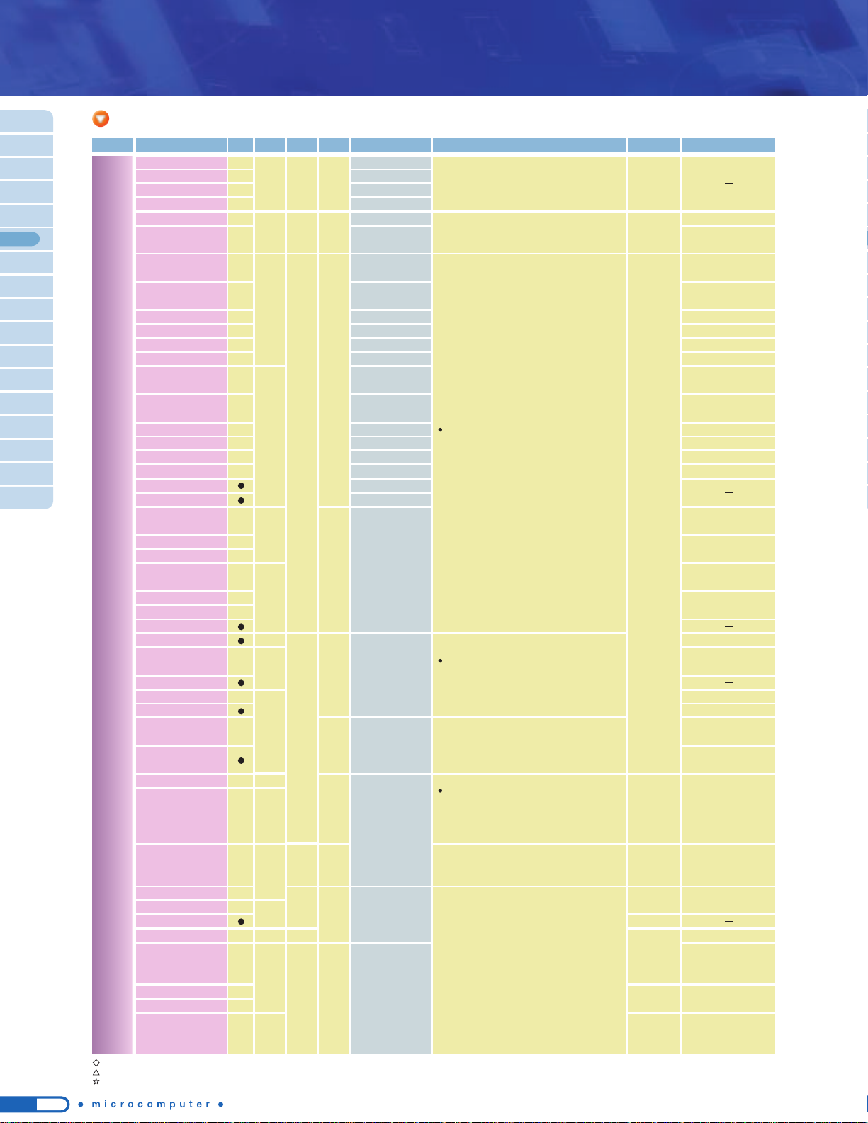
● Sine wave drive
● Rotor position detection function
●
Motor control timer and timer capture
●
PWM waveform generation function
● Overload protection function
● Abnormality protection function
●
Automatic commutation start and
automatic position detection start
● AD converter trigger generation
function
Series
Name
Part Number
Flash
ROM
(bytes)
RAM
(bytes)
Supply
Voltage (V)
PMD
(channel)
I/O Additional Functions Version with OTP/Flash Package
TMP88CH40NG/MG
TMP88CH40IMG
TMP88CH41NG/UG
TMP88CH41IUG
/SUG
T5BE2 T5BE1
TMP88PS42NG/FG
TMP88PS43FG
TMP88CS42NG/FG
TMP88CS43FG
16 K
64 K
870/X
DSP
TX19A
512
2K
19
33
221K32K
1
1
2
4.5 to 5.5
4.5 to 5.5
3.0 to 3.6
55
71
●
10-bit AD converter
●
UART
●
SIO
●
10-bit AD converter
●
UART/SIO
●
PWM
●
Encoder input
●
10-bit AD converter
●
UART
●
SIO
●
PWM
SDIP64/QFP64
(14
20mm)
LQFP44(10
10mm)
TMP88PH41NG/UG
SDIP42/LQFP44(10 10mm)
TMP88PH40NG/MG
SDIP28/SOP28
SOP28
QFP80(14
20mm)
TMP19A71CYUG/FG
-TMP88FW44FG
256 K
120K
10K4K75 2
2
3.0 to 3.6
4.5 to 5.5
91
●
10-bit AD converter
●
UART/SIO
●
PWM
●
Encoder input
●
10-bit AD converter
●
UART
●
SIO
●
PWM
LQFP100(14 14mm)/
QFP100(14
20mm)
TMP19A71FYUG/FG
QFP100(14 20mm)
-TMP88FW45FG
120K 4K 2
4.5 to 5.5
71
●
10-bit AD converter
●
UART
●
SIO
●
PWM
QFP80(14 20mm)
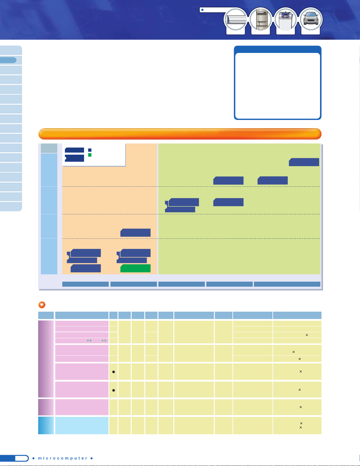
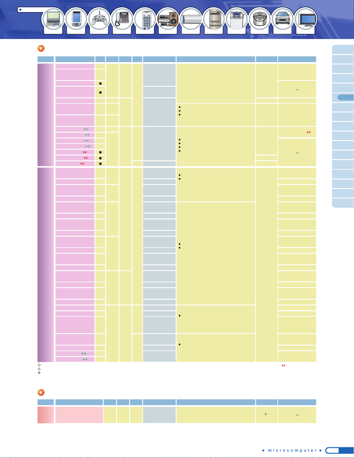
PMD 1ch
Second-generation PMD
4-channel 10-bit ADC
Second-generation PMD
8-channel 10-bit ADC
Third-generation PMD
8-channel 10-bit
high-speed
ADC
PMD 2ch
ROM
size
120/
256 K
64 K
32 K
16 K
*
For details of the products listed above, see the "Part Number List".
++: Under planning
TMP88CH41TMP88CH40
T5BE2
Second-generation PMD
16-channel 10-bit ADC
TMP88CS42
TMP88CH40I
TMP88CH41I/S
Second-generation PMD
16-channel 10-bit ADC
Second-generation PMD
Flash ROM
TMP88CS43
Second-generation PMD
Flash ROM
TMP88FW45
Third-generation
PMD
8- and 11-channel
10-bit high-speed ADCs
TMP19A71
TMP88FW44
*
PMD : Programmable Motor Driver
These microcontrollers with a motor control circuit incorporate an
inverter control function for 3-phase DC and AC motors. The motor
control circuit supports hardware configuration where motor drive
signals are linked with feedback signals from the motor, thus
controlling the motor with less load imposed on the
CPU. The line-up
includes a variety of microcontrollers supporting
120-degree
commutation and vector control.
■ Microcontrollers with motor control circuit (PMD)
28-pin 42-/44-pin 64-pin 80-pin 100-pin
8-bit microcontrollers with motor control circuit (PMD)
Microcontrollers Listed by Function / Application
Main functions
Product line-up
*
Some of the flash memories use the SuperFlash® technology under the license of Silicon Storage Technology, Inc. SuperFlash® is a registered trademark of Silicon Storage Technology, Inc.
TMP88PH40MG
TMP88PH41UG LQFP44(10x10mm)
: In mass production
: Under planning
SOP/QFP
DIP
13
Applications
Electronic dictionaries
PDAs Air conditioners Refrigerators
Washing machines
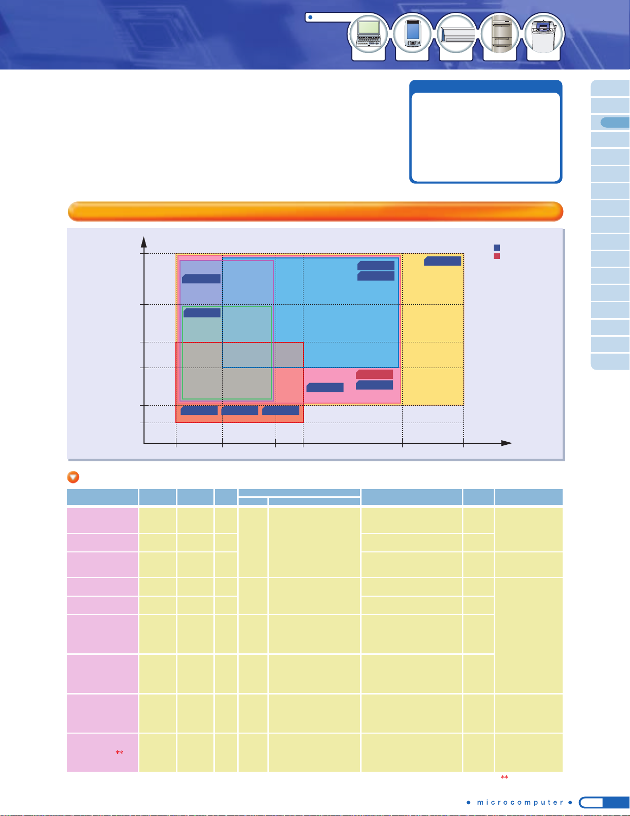
● Monochrome/Gray/Color LCD
controller
● Memory interface:
SDRAM, NAND Flash, SD card
● Large-capacity memory access
MMU
● Touch Screen interface
Part Number
ROM
(bytes)
RAM
(bytes)
Supply
Voltage (V)
I/O Additional Functions
LCD-CTRL
Display SizeColor
Package
TMP91C016FG
31
W/B
W/B
16
Gray
Gray/
Color
64seg. x 32com.
to
360seg. x 240com.
128seg. x 128com.
to
640seg. x 480com.
64seg. x 64com.
to
Color: 320seg. x 320com.
Gray: 960seg. x 480com.
-- 1.8 to 3.6
●
MMU (105MB)
●
DRAM controller
●
Display data X/Y axis conversion circuit (8 x 8)
TMP91C025FG
38-- 2.4 to 3.6
●
MMU (72MB)
●
Touch Screen interface
TMP91C820AFG
778K8K 2.7 to 3.6
●
MMU (136MB)
●
SDRAM controller
TMP92CH21FG
8216K
8K
(Boot)
2.7 to 3.6
●
MMU (512MB)
●
SDRAM controller
●
NAND Flash interface
●
Touch Screen interface
●
USB1.1 interface
64seg. x 64com.
to
640seg. x 480com.
TMP92CA25FG
9210K 2.7 to 3.6
●
MMU (512MB)
●
SDRAM controller
●
NAND Flash interface
●
Touch Screen interface
●
SPI interface
TMP92C820FG
838K-
-
Gray/
Color
136
TMP92CZ26AXBG
288K
1.4 to 1.6
3.0 to 3.6
(Two power
supplies)
●
MMU (3.1GB)
●
SDRAM controller
●
MLC NAND Flash interface
●
USB1.1 interface
●
SPI interface
8K
(Boot)
3.0 to 3.6
●
MMU (136MB)
●
SDRAM controller
TMP91C815FG
618K- 1.8 to 3.6
●
MMU (136MB)
LQFP100
(14 x 14mm)
LQFP128
(14 x 14mm)
FBGA228
(15 x 15mm,
0.8-mm pitch)
LQFP144
(16 x 16mm)
480
Common
Segment
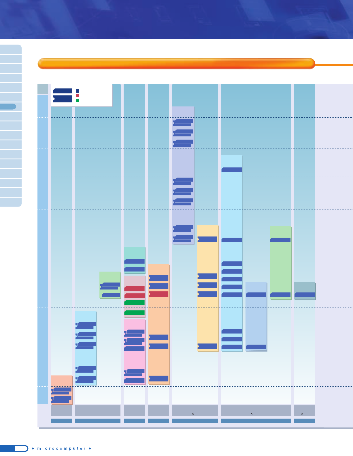
The following microcontrollers contain LCD controller circuitry that
supports monochrome and color STN/TFT. The line-up thus supports
a wide range of LCDs with different sizes.
■ Microcontrollers with LCD controller
320
240
128
64
64
128 320 360 640 960
32
Monochrome
Monochrome /
Gray
Monochrome /
Gray
Monochrome
Color
TMP92CA25
Monochrome /
Gray / Color
TMP92CZ26A
TMP92CF29
64K / 256K /
16M Colors
TMP92CZ26A
TMP91C820A
TMP92C820
TMP92CH21
TMP92CH21
TMP91C016 TMP91C025 TMP91C815
*
For details of the products listed above, see the "Part Number List".
16-/32-bit microcontrollers with LCD controller
64seg.
x
64com.
to
64K
or more colors
:320seg.
x
480com.
4K
or fewer colors
:
640seg.
x
480com.
Gray
Gray/
Color
92
TMP92CF29FG
144K
1.4 to 1.6
3.0 to 3.6
(Two power
supplies)
●
MMU (2.1GB)
●
SDRAM controller
●
MLC NAND Flash interface
●
USB1.1 interface
●
SPI interface
8K
(Boot)
LQFP176
(20 x 20mm)
64seg.
x
64com.
to
64K
or more colors
:320seg.
x
480com.
4K
or fewer colors
:640seg.
x
480com.
Gray
Main functions
Product line-up
: In mass production
: Under development
: Under development
14
23 seg. x 4 com.
TMP86PH22
TMP86CH22
TMP86C822
64-pin44-pin 80-pin 100-pin 144-pin
LQFP
(
10 x 10mm
)
/
QFP
(
14 x 14mm
)
SDIP64/LQFP
(
10 x 10mm
)
QFP
(
14 x 20mm
)
LQFP
(
12 x 12mm
)
QFP
(
14 x 20mm
)
LQFP
(
14 x 14mm
)
LQFP
(
16 x 16mm
)
32seg. x 4 com.
8-bit AD converter:
8 channels
40seg. x 4 com.
On-chip voltage booster
40 seg .x 4 com.
8-bit AD converter:
8 channels
On-chip voltage
booster
ROM
size
4 K
8 K
16 K
24 K
32 K
48 K
60 K
64 K
128 K
42- / 44-pin
SDIP / QFP
ROM
size
2 K
4 K
24seg. x 4 com.
On-chip voltage
booster
60seg. x 16com.
On-chip voltage
booster
8-bit
AD converter:
8 channels
40 seg. x 4 com.
On-chip voltage
booster
10-bit
AD converter:
8 channels
24 seg. x 4 com.
TMP87CM29
TMP87CK29
TMP87CH29
LQFP44
(
10 x 10mm
)
32 seg. x 4 com.
On-chip voltage
booster
TMP86PM29B
TMP86FM29
TMP86CM29L
TMP86FM26
TMP86CM29B
TMP86CH21A
TMP86CH29B
TMP86C829B
TMP86C820
TMP86C420
32 seg. x 4 com.
TMP86PS23
TMP86FS23
TMP86CP23A
TMP86CM23A
TMP86PM23
TMP87PP21
TMP87CP21C
TMP87CM21C
TMP87CM21C
TMP87PP21
TMP86PS27
TMP86CP27A
TMP86CM27
TMP86FS28 TMP86FS28
TMP86CS28 TMP86CS28
TMP87CP21C
TMP87CH21C
TMP87CH21C
TMP86FP24
TMP86FS27
TMP87PP23
TMP87CP23
TMP86FM25
TMP86CM25A
TMP87CM23A
TMP87PP24A
TMP87CP24A
TMP87CM24A
TMP86CM25
TMP93CS20
20 seg x 4 com.
8-bit
AD converter:
4 channels
TMP47C222
TMP47C422
40 seg. x 4 com.
Not voltage
booster type
TMP91FW40
TMP91CW40
60seg. x 16com.
On-chip voltage
booster
8-bit
AD converter:
8 channels
TMP86CS25A
TMP86CS25AD
TMP86PS25
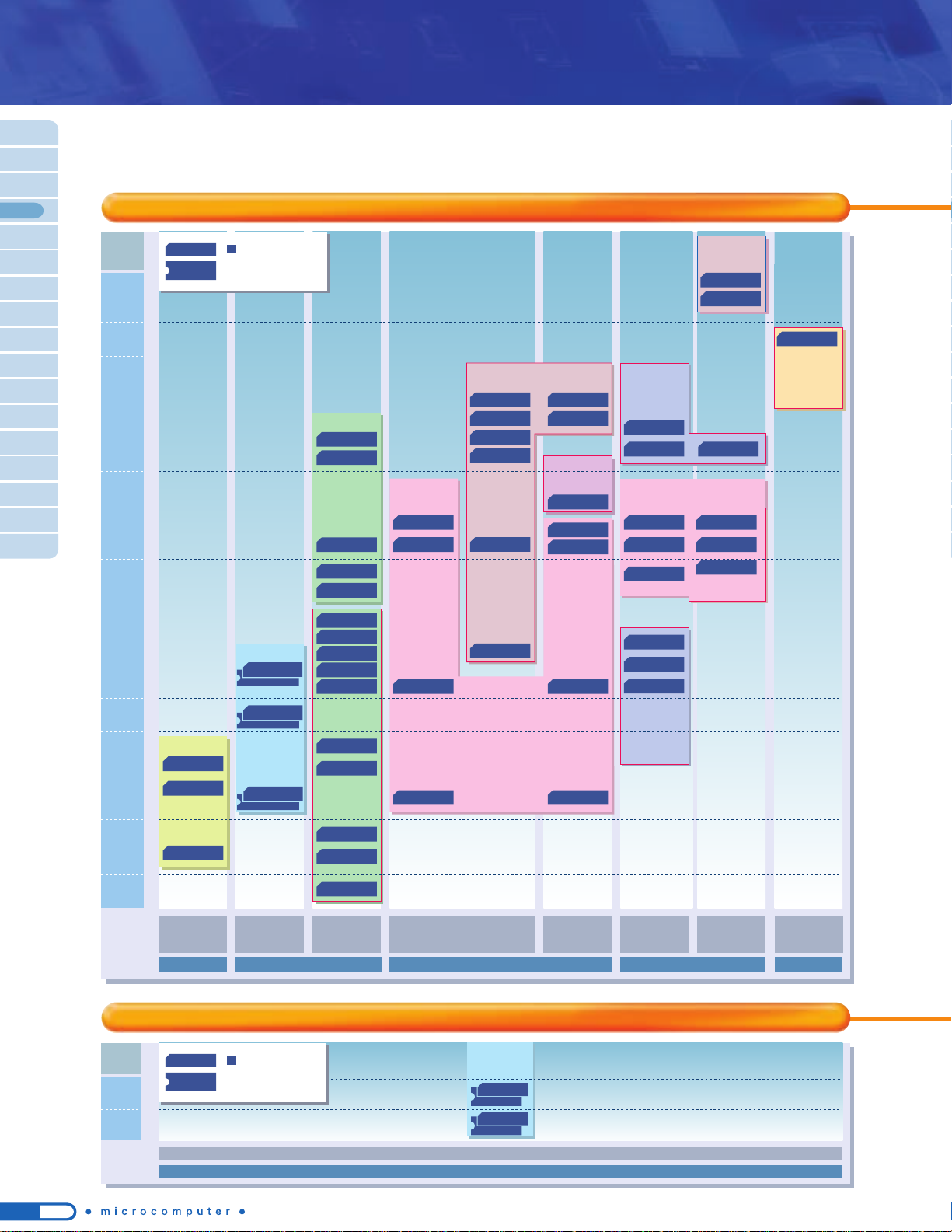
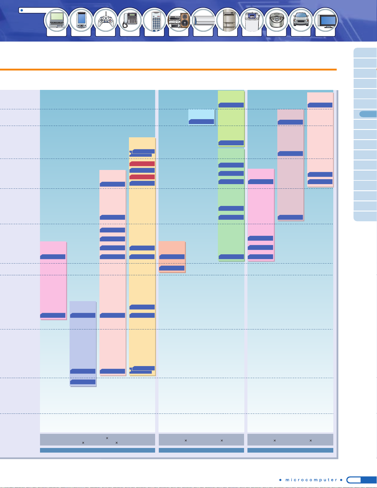
The following microcontrollers contain LCD driver circuitry. Some products also incorporate a voltage booster,
enabling stable LCD display even at low operating voltages and realizing low power consumption.
■ Microcontrollers with LCD driver
Microcontrollers Listed by Function / Application
: In mass production
QFP
DIP
4-bit microcontrollers with LCD driver
8-/16-bit microcontrollers with LCD driver
: In mass production
QFP
DIP
15
Applications
Game machines Telephones Remote controls Audio systems Air conditioners Refrigerators
Washing machines
Rice cookers
Series
Name
Part Number
ROM
(bytes)
RAM
(bytes)
I/O LCD Driver Additional Functions
Power
Voltage (V)
Package
Series
Name
Part Number
ROM
(bytes)
RAM
(bytes)
I/O LCD Driver Additional Functions
Power
Voltage (V)
Package
Series
Name
Part Number
ROM
(bytes)
RAM
(bytes)
I/O LCD Driver Additional Functions
Power
Voltage (V)
Package
16 K
32 K
60 K
32 K
: Guaranteed over the ambient temperature (Topr) range of -20oC to 85oC at 1.8 V to 2.0 V.
: Guaranteed over the ambient temperature (Topr) range of -20oC to 85oC at 2.7 V to 3.0 V.
*
For details of the products listed above, see the "Part Number List".
TMP87CH21CFG/CDFG
TMP87CM21CFG/CDFG
TMP87CP21CFG/CDFG
TMP87CM23AFG
TMP87CP23FG
TMP87CM24AFG
TMP87CP24AFG
TMP87CH29NG/UG
TMP87CK29NG/UG
TMP87CM29NG/UG
870
1 K
2 K
1 K
2 K
2K
1 K
40 seg. X 4 com.
40 seg. X 4 com.
(On-chip voltage booster)
32 seg. X 4 com.
24 seg. X 4 com.
23 seg. X 4 com.
●
8-bit AD converter: 8 channels
●
8-bit SIO: 2 channels
●
16-bit timer/counter: 2 channels,
8-bit timer/counter: 2 channels
●
8-bit AD converter: 5 channels
●
8-bit
UART
: 1 channel
●
18-bit timer/counter: 1 channel,
8-bit timer/counter: 4 channels
2.7 to 5.5
2.7 to 5.5
2.2 to 5.5
QFP100
(
14 X 20mm
)
LQFP100
(
14 X 14mm
)
QFP80 (14 X 20mm
)
LQFP80 (12 X 12mm
)
QFP80 (14 X 20mm
)
LQFP80 (12 X 12mm
)
SDIP64
LQFP64
(
10 X 10mm
)
870/C
256
512
1K
512
1.5K
39
39
41
48
54
42
24 seg. X 4 com.
(On-chip voltage booster)
60 seg. X 16 com.
(On-chip voltage booster)
32 seg. X 4 com.
(On-chip voltage booster)
●
8-bit AD converter: 8 channels
●
8-bit SIO: 1 channel
●
18-bit timer/counter: 1 channel, 8-bit timer/counter: 2 channels
●
8-bit AD converter: 4 channels
●
8-bit SIO: 1 channel,
UART
: 1 channel
●
18-bit timer/counter: 1 channel, 8-bit timer/counter: 2 channels
●
8-bit AD converter: 8 channels
●
8-bit SIO: 1 channel
●
18-bit timer/counter: 1 channel, 8-bit timer/counter: 4 channels
●
10-bit AD converter: 8 channels
●
8-bit SIO/
UART
: 1 channel
●
18-bit timer/counter: 1 channel, 8-bit timer/counter: 4 channels
●
8-bit SIO/UART: 1 channel, 8-bit UART: 1 channel
●
18-bit timer/counter: 1 channel, 8-bit timer/counter: 4 channels
●
Real-time clock with calendar
●
10-bit AD converter: 8 channels
●
8-bit SIO: 1 channel,
8-bit
UART
: 1 channel
●
18-bit timer/counter: 1 channel, 8-bit timer/counter: 4 channels
●
Multiply-accumulate calculator (MAC)
●
10-bit AD converter: 8 channels
●
8-bit SIO: 1 channel, 8-bit SIO/UART: 1 channel
●
16-bit timer/counter: 2 channels, 8-bit timer/counter: 2 channels
●
Program patch logic
●
8-bit AD converter: 8 channels
●
8-bit SIO/
UART
: 1 channel,
8-bit SIO
: 1 channel
●
18-bit timer/counter: 1 channel,
8-bit timer/counter: 4 channels
1.8 to 5.5
1.8 to 5.5
1.8 to 5.5
1.8 to 3.6
1.8 to 3.6
1.8 to 3.6
1.8 to 5.5
1.8 to 5.5
1.8 to 5.5
1.8 to 3.6
LQFP64
(
10 X 10mm
)
QFP64
(
14 X 14mm
)
LQFP64
(
10
10mm
)
QFP64
(
14 X 14mm
)
LQFP64
(
10 X 10mm
)
LQFP80
(
12 X 12mm
)
TMP93CS20FG
TMP91CW40FG
TMP91FW40FG
64 K 2 K 88
40 seg. x 4 com.
(On-chip voltage booster)
● Serial interface: 3 channels
● 10-bit AD converter: 8 channels
● 16-bit timer/counter: 4 channels,
8-bit timer/counter: 4 channels
5V
10%
3V
10%
LQFP144
(
16 x 16 mm
)
900/L
2 K
2 K
QFP100
(
14 X 20mm
)
LQFP100 (14 X 14mm
)
55
40 seg. X 4 com.
(On-chip voltage booster)
●
10-bit AD converter: 8 channels
●
8-bit
UART
: 1 channel,
8-bit SIO
: 1 channel
●
10-bit timer/counter: 1 channel,
8-bit timer/counter: 2 channels
2.7 to 5.5
1 K
QFP80
(
14 X 20mm
)
52
70
69
43
LQFP64
(
10 X 10mm
)
LQFP64
(
10 X 10mm
)
QFP64
(
14 X 14mm
)
LQFP64
(
10 X 10mm
)
LQFP44
(
10 X 10mm
)
32 seg. X 4 com.
16 K
32 K
48 K
32 K
48 K
32 K
48 K
16K
24K
32K
4 K
8 K
32K
8 K
TMP47C222N/F/U
TMP47C422N/F/U
2 K
4 K
192
256
22
20 seg. x 4 com.
47E
● 8-bit AD converter: 4 channels
● 8-bit SIO: 1 channel
●
Pulse output: remote control transmission carrier
2.5 to 5.5
SDIP42
QFP44
(
14 x 14 mm
)
QFP44
(
10 x 10 mm
)
2.7 to 5.5
2 K
62
40 seg. X 4 com.
(On-chip voltage booster)
●
10-bit AD converter: 8 channels
●
8-bit SIO/
UART
: 1 channel,
8-bit
UART
: 1 channel
●
16-bit timer/counter: 2 channel,
8-bit timer/counter: 4 channels
2.7 to 5.5
128 K 4 K 61
40 seg. x 4 com.
(Not voltage booster type)
● Serial interface: 4 channels
● 10-bit AD converter: 12 channels
● 16-bit timer/counter: 3 channels,
8-bit timer/couter: 4 channels
2.7 to 3.6
LQFP100
(
14 x 14 mm
)
900/L1
16 K
8 K
512 32
48K
60K
48K
48K
60K
16-bit microcontrollers with LCD driver
8-bit microcontrollers with LCD driver
4-bit microcontrollers with LCD driver
TMP86FM26UG
TMP86C829BUG/BFG
TMP86CH29BUG/BFG
TMP86CM29BUG/BFG
TMP86CM29LUG
TMP86FM29UG/FG
TMP86CM23AUG
♦
TMP86CP23AUG
♦
TMP86FS23UG ▲
TMP86FP24FG
TMP86CM27FG
TMP86CP27AFG
TMP86FS27FG
TMP86CM25FG
TMP86CM25AFG
TMP86FS28FG/DFG ▲
TMP86CH22UG ♦
TMP86C822UG ♦
TMP86CS25AFG
♦
TMP86CS25ADFG
♦
TMP86CS28FG/DFG ▲
TMP86C420UG/FG
TMP86C820UG/FG
TMP86CH21FG
TMP86CH21AUG ♦
*
Some of the flash memories use the SuperFlash® technology under the license of Silicon Storage Technology, Inc. SuperFlash® is a registered trademark of Silicon Storage Technology, Inc.
1.5K
32K
16 K
16
Applications
ROM
size
32 K
24 K
16 K
8 K
40 K
48 K
60 K
64 K
72 K
96 K
128 K
870/C Series
870/X
Series
64-pin 80-pin 100-pin
QFP/SDIP QFP
QFP
Audio systems Air conditioners Refrigerators
Washing machines
DVDs
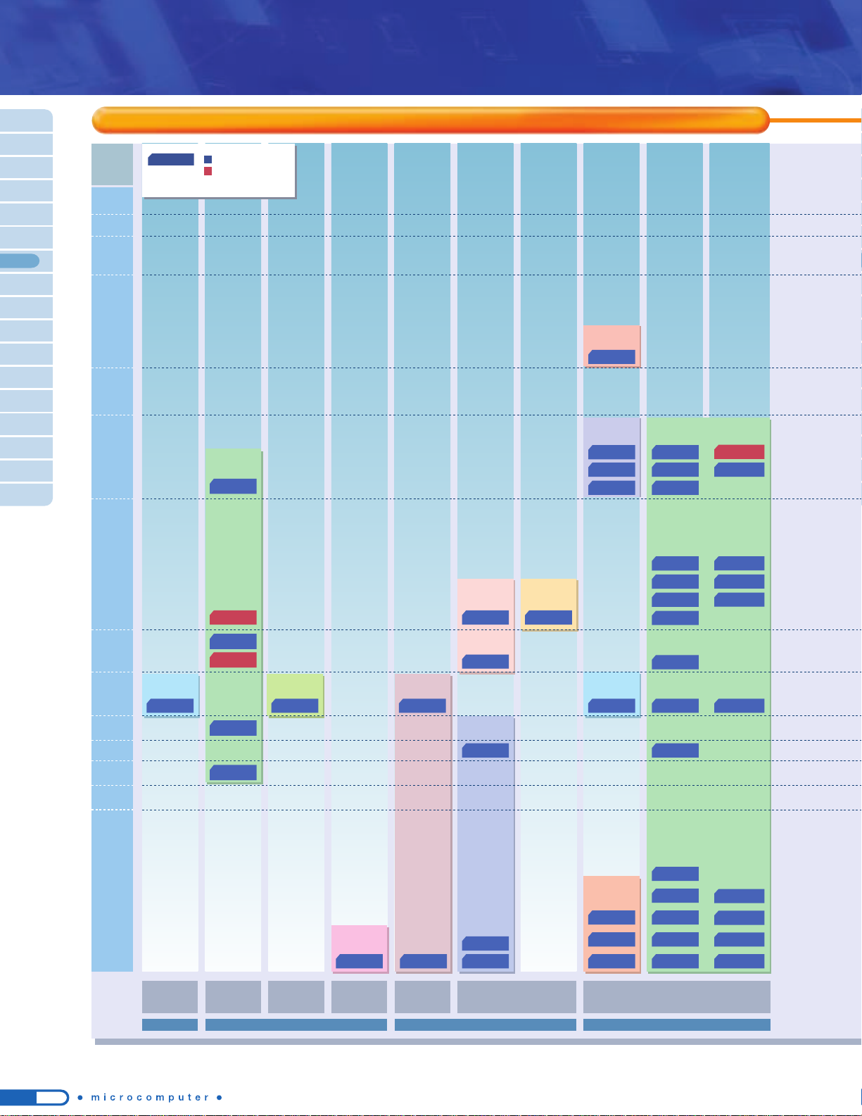
The following microcontrollers incorporate high breakdown voltage output for directly driving a fluorescent display tube and a display circuit for automatically transferring display data to a port. In addition to existing products, such as a VFT driver circuit which can display digits on a segmented display, Toshiba offers a line-up of
products which support automatic display on universal-grid display tubes.
■ Microcontrollers with fluorescent display tube driver
Microcontrollers Listed by
Function
/
Application
8-/16-bit microcontrollers with fluorescent display tube driver
: In mass production
: Under development
QFP
DIP
TMP87C814
TMP87CH14
TMP87CK14
TMP87CM14
TMP87PM14
870
Series
TMP87PS71A
TMP87CS71B
TMP88PU74
TMP88CU74
TMP88CP77
TMP88CS77
TMP88PU77
TMP88CU77
TMP87PM74
TMP87CM74A
TMP87CH74A
TMP87PM75
TMP87CM75
TMP87CH75
TMP86PM74A
TMP86CM74A
TMP86CK74A
TMP86PM72
TMP86CM72
TMP86CH72
8-bit microcontrollers with fluorescent display tube driver
ROM
(bytes)
RAM
(bytes)
Series
Name
Part Number I
/ OVFT Driver(Fluorescent Tube Driver)
Additional Functions Package
TMP87C814NG/FG
TMP87CH14NG/FG
TMP87CK14NG/FG
TMP87CM14NG/FG
TMP87CS71BFG
TMP87CH74AFG
TMP87CM74AFG
TMP87CH75FG
TMP87CM75FG
TMP86CK74AFG
TMP86CM74AFG
TMP86CH72FG
TMP86CM72FG
TMP88CU74F
G
TMP88CP77FG
TMP88CS77FG
TMP88CU77FG
8 K
16 K
24 K
32 K
60 K
16 K
32 K
16 K
32 K
24 K
32 K
16 K
32 K
96 K
48 K
64 K
96 K
512
1 K
2 K
512
1K
512
1K
1K
2K
1K
2K
1K
2K
3K
870
870/C
55
73
71
70
89
54
●
8-bit SIO: 1 channel
●
16-bit timer/counter: 2 channels,
8-bit timer/counter: 2 channels
●
8-bit AD converter: 12 channels ●
8-bit SIO: 2 channels
●
16-bit timer/counter: 3 channels,
8-bit timer/counter: 1 channel
●
8-bit AD converter: 8 channels
●
8-bit SIO: 1 channel
●
16-bit timer/counter: 2 channels,
8-bit timer/counter: 2 channels
●
8-bit AD converter: 12 channels
●
8-bit SIO: 2 channels
●
16-bit timer/counter: 2 channels,
8-bit timer/counter: 2 channels
●
AD converter input: 6 channels
●
8-bit SIO: 1 channel
●
High-speed serial output
QFP80
(
14 x 20mm
)
QFP80
(
14 x 20mm
)
QFP100
(
14 x 20mm
)
QFP80
(
14 x 20mm
)
16 seg. x 16 dig.
88
SDIP64/
QFP64
(
14 x 20mm
)
Maximum breakdown
voltage:
40 V on each of 24 pins
Maximum breakdown voltage:
40 V on each of 37 pins
Programmable grid scan output
Maximum breakdown voltage:
40 V on each of 51 pins
Programmable grid scan output
●
8-bit AD converter: 8 channels ● 8-bit SIO: 1 channel
●
16-bit timer/counter: 2 channels,
8-bit timer/counter: 2 channels
QFP100
(
14 x 20mm
)
Maximum breakdown voltage:
41 V on each of 37 pins
Programmable grid scan output
●
8-bit AD converter: 6 channels ●
8-bit SIO: 1 channel
●
16-bit timer/counter: 1 channel,
8-bit timer/counter: 2 channels ●
I2C bus: 1 channel
QFP64
(
14 x 14mm
)
Maximum breakdown voltage:
41 V on each of 32 pins
Programmable grid scan output
Maximum breakdown voltage:
40 V on each of 37 pins
Programmable grid scan output
Maximum breakdown voltage:
40 V on each of 53 pins
Programmable grid scan output
870/X
71
*
For details of the products listed above, see the "Part Number List".
17
■ General-purpose microcontrollers in compact packages
This comprehensive product line comes in compact packages, including SOPs, SSOPs and 7 mm x 7 mm
48-pin flat packages.
20-pin 28-pin 30-pin 32-pin 42-pin 48-pin44-pin
SOP/DIP SOP/SDIP SDIP
LQFP
SSOP
ROM
size
4 K
2 K
64 K
8 K
16 K
48 K
32 K
SDIP LQFP/QFP
Applications
Electronic dictionaries
PDAs Game machines Telephones Remote controls Audio systems Air conditioners Refrigerators
Washing machines
Rice cookers TVsAutomotive
General-purpose microcontrollers in compact packages
TMP86P202MG/NG
TMP86P203MG/NG
TMP86C407MG/NG
TMP86C407IMG/NG
TMP86C407SMG/NG
TMP86C807MG/NG
TMP86C807IMG/NG
TMP86C807SMG/NG
TMP86F807MG/NG
TMP88CH40MG/NG
TMP88CS34NG/FG
TMP88CS38ANG/F
TMP88CS38BNG/NG
TMP88CP34NG/FG
TMP88CP38ANG/F
TMP88CM38ANG/F
TMP88CH41NG/UG
TMP88CM38BNG/F
TMP88CP38BNG/FG
TMP86C408DMG
TMP86C408IDMG
TMP86C408SDMG
TMP86C808DMG
TMP86C808IDMG
TMP86C808SDMG
TMP86F808DMG
TMP86C892IDMG
TMP86C892SDMG
TMP86CH12MG
TMP88CH40IMG
TMP86FH12MG
TMP86FH92DMG
TMP86FH92IDMG
TMP86CH92IDMG
TMP86CH92SDMG
TMP86F409NG
TMP86C809NG
TMP86F809NG
TMP86CH09NG
TMP86FH09NG
TMP86FH93NG
TMP86C846NG
TMP86CH06NG
TMP86CH46ANG
TMP86FH46ANG
TMP86CM46ANG
TMP86C845UG
TMP86C822UG
TMP86C847UG
TMP86C847IUG
TMP86C847SUG
TMP86CH47SUG
TMP86FH47AUG
TMP86CH87RUG
TMP88CH41IUG
TMP88CH41SUG
TMP86CM47AUG
TMP86CM87RUG
TMP86CH06AUG
TMP86CH47AUG
TMP86CH47IUG
TMP93CS36UG
TMP86FH47ADUG
: In mass production
: Under development
: Under planning
SOP/QFP
DIP
18
Microcontrollers Listed by Function / Application
870/C
TMP86P202MG
SOP20
●
8-bit AD converter: 4 channels
●
8-bit timer/counter: 2 channels
TMP86P202PG
DIP20
TMP86P203MG
2 K 128 14
SOP20
3.3 to 5.5
TMP86P203PG
TMP86CH06NG
DIP20
TMP86CH06AUG
♦
SDIP42
●
8-bit SIO/UART (switchable): 1 channel
●
UART: 1 channel
●
16-bit timer/counter: 1 channel, 8-bit timer/counter: 2 channels
SEI
●
UART: 1 channel
●
8-bit AD converter: 6 channels
●
16-bit timer/counter: 1 channel, 8-bit timer/counter: 2 channels
SEI
●
UART: 1 channel
●
10-bit AD converter: 6 channels
●
16-bit timer/counter: 1 channel, 8-bit timer/counter: 2 channels
●
8-bit SIO: 1 channel
●
UART: 1 channel
●
10-bit AD converter: 8 channels
●
16-bit timer/counter: 1 channel, 10-bit timer/counter: 1 channel,
8-bit timer/counter: 2 channels
●
8-bit SIO: 1 channel
●
10-bit AD converter: 8 channels
●
8-bit timer/counter: 2 channels
●
8-bit SIO: 1 channel
●
UART: 1 channel
●
10-bit AD converter: 8 channels
●
16-bit timer/counter: 1 channel, 8-bit timer/counter: 2 channels
LCD
●
8-bit SIO: 1 channel
●
UART: 1 channel
●
8-bit AD converter: 4 channels
●
18-bit timer/counter: 1 channel, 8-bit timer/counter: 2 channels
TMP86PH06NG
16 K 512 35
1.8 to 5.5
TMP86PH06UG
TMP86C407MG
256
22
SOP28
2.7 to 5.5
TMP86P807MG
TMP86F807MG
TMP86C407NG
SDIP28
TMP86P807NG
TMP86F807NG
TMP86C407IMG
4 K
SOP28
TMP86P807MG
TMP86C407ING
SDIP28
TMP86P807NG
TMP86C407SMG
★
SOP28
TMP86P807MG
TMP86C407SNG
★
SDIP28
TMP86P807NG
TMP86C807MG
8 K
SOP28
TMP86P807MG
TMP86F807MG
TMP86C807NG
SDIP28
TMP86P807NG
TMP86F807NG
TMP86C807IMG
SOP28
TMP86P807MG
TMP86C807ING
SDIP28
TMP86P807NG
TMP86C807SMG
★
SOP28
TMP86P807MG
TMP86C807SNG
★
SDIP28
TMP86P807NG
TMP86F807MG
SOP28
TMP86F807NG
SDIP28
TMP86C408DMG
SSOP30
TMP86P808DMG
TMP86F808DMG
TMP86P808DMG
TMP86F808DMG
4 K
24
TMP86C408IDMG
TMP86P808DMG
TMP86P808DMG
TMP86C408SDMG
★
TMP86C808DMG
8 K
TMP86C808IDMG
TMP86C808SDMG ★
TMP86F808DMG
TMP86F409NG ▲
TMP86C809NG
8 K
4 K
512
26 SDIP32
TMP86FH09NG ▲
TMP86F809NG ▲
TMP86FH09NG ▲
TMP86F809NG ▲
TMP86CH09NG
TMP86FH09NG ▲
16 K
TMP86CH12MG
24 SSOP30
TMP86FH12MG ▲
TMP86FH12MG ▲
TMP86C822UG
♦
8 K
33
LQFP44
(10 x 10mm)
1.8 to 5.5
TMP86PH22UG
♦
TMP86CH22UG
♦
16 K
TMP86C845UG
8 K
256 35
SDIP42
2.7 to 5.5
TMP86PM47AUG
TMP86PH47UG
TMP86FH47AUG
▲
TMP86C846NG
512
33
1.8 to 5.5
TMP86PH46NG
♦
TMP86PM46NG
TMP86FH46ANG
▲
TMP86CH46ANG
♦
16 K
TMP86FH46ANG ▲
TMP86CM46ANG
8 K
1 K
2.7 to 5.5
TMP86PM46NG
512
35
LQFP44
(10 x 10mm)
1.8 to 5.5
TMP86PM47AUG
TMP86PH47UG
♦
TMP86FH47AUG ▲
TMP86C847UG
TMP86C847IUG
2.7 to 5.5
TMP86PM47AUG
TMP86PH47UG
TMP86FH47AUG
TMP86C847SUG
★
16 K
32 K
1.8 to 5.5
TMP86PM47AUG
TMP86PH47UG
♦
TMP86FH47AUG ▲
TMP86FH47ADUG ▲
TMP86CH47AUG
♦
8-bit microcontrollers (TLCS-870/C Series)
Part Number Flash
ROM
(bytes)
RAM
(bytes)
Series
Name
I/O Additional FunctionsCompact Package Supply Voltage (V) Version with OTP/Flash
LQFP44
(10 x 10mm)
: Guaranteed over the ambient temperature (Topr) range of -40oC to 125oC.
: Guaranteed over the ambient temperature (Topr) range of -20oC to 85oC at 1.8 V to 2.0 V.
: Guaranteed over the ambient temperature (Topr) range of -20oC to 85oC at 2.7 V to 3.0 V.
19
Applications
Electronic dictionaries
PDAs Game machines Telephones Remote controls Audio systems Air conditioners Refrigerators
Washing machines
Rice cookers TVsAutomotive
TMP86CH47IUG
TMP86CH47SUG
★
TMP86FH47AUG ▲
TMP86FH47ADUG ▲
TMP86CM47AUG
TMP86C892IDMG
TMP86C892SDMG ★
TMP86CH92IDMG
TMP86CH92SDMG ★
TMP86FH92DMG
TMP86FH92IDMG
TMP86FH93NG
TMP86CH87RUG
TMP86CM87RUG
SDIP32
SDIP42
SSOP30
16 K
32 K
8 K
16 K
48 K
64 K
32 K
48 K
64 K
16 K
16 K
32 K
512
1 K
512
2 K
512
1.5 K
33
35
24
19
33
26
2.7 to 5.5
1.8 to 5.5
3.0 to 5.5
2.7 to 5.5
4.5 to 5.5
4.5 to 5.5
2.7 to 5.5
870/C
870/X
16-bit microcontrollers (TLCS-900/L Series)
8-bit microcontrollers (TLCS-870/C Series,TLCS-870/X Series)
Part Number Flash
ROM
(bytes)
RAM
(bytes)
Series
Name
I/O Additional FunctionsCompact Package Supply Voltage (V) Version with OTP/Flash
Part Number
ROM
(bytes)
RAM
(bytes)
Series
Name
I/O Additional FunctionsCompact Package Supply Voltage (V) Version with OTP/Flash
: Guaranteed over the ambient temperature (Topr) range of -40oC to 125oC.
CAN
SEI
UART: 1 channel
●
10-bit AD converter: 14 channels
●
16-bit timer/counter: 1 channel, 8-bit timer/counter: 2 channels
SEI
UART: 1 channel
I2C/UART
(switchable)
10-bit AD converter: 6 channels
●
16-bit timer/counter: 1 channel, 8-bit timer/counter: 2 channels
I2C
: 1 channel
PWM: 4 channels
●
8-bit AD converter: 6 channels
●
16-bit timer/counter: 2 channels, 8-bit timer/counter: 2 channels
●
Remote control detection
●
Program patch logic
I2C
: 1 channels
PWM: 10 channels
●
8-bit AD converter: 6 channels
●
16-bit timer/counter: 2 channels, 8-bit timer/counter: 2 channels
●
Remote control detection
●
Program patch logic
●
8-bit SIO: 1 channel
UART: 1 channel
●
10-bit AD converter: 4 channels
●
16-bit timer/counter: 1 channel, 8-bit timer/counter: 2 channels
●
Motor control
●
8-bit SIO: 1 channel
UART: 1 channel
●
10-bit AD converter: 8 channels
●
16-bit timer/counter: 2 channels, 8-bit timer/counter: 2 channels
●
Motor control
LQFP44
(10 x 10mm)
LQFP44
(10
x
10mm)
QFP44
(14
x
14mm)
SDIP42
QFP44
(14
x
14mm)
SDIP42
QFP44
(14
x
14mm)
SDIP42
QFP44
(14
x
14mm)
SDIP42
QFP44
(14
x
14mm)
SDIP42
QFP44
(14
x
14mm)
SDIP42
QFP44
(14
x
14mm)
SDIP42
SOP28
SOP28
SDIP28
SDIP42
QFP44
(14
x
14mm)
LQFP44
(10 x 10mm)
LQFP44
(10 x 10mm)
LQFP48
(7
x
7mm)
●
8-bit SIO: 1 channel
●
UART: 1 channel
●
10-bit AD converter: 8 channels
●
16-bit timer/counter: 1 channel, 8-bit timer/counter: 2 channels
TMP86PM47AUG
TMP86PM87RUG
TMP86FH92IDMG
TMP88PS38BNG
TMP88PS34NG
TMP88PS34FG
TMP88PS34NG
TMP88PS34FG
TMP88PS38NG
TMP88PS38FG
TMP88PS38BNG
TMP88PS38BFG
TMP88PS38NG
TMP88PS38FG
TMP88PS38BNG
TMP88PS38BFG
TMP88PS38NG
TMP88PS38FG
TMP88PS38BFG
TMP88PH40MG
TMP88PH40NG
TMP88PH40MG
TMP88PH41UG
TMP88PH41UG
TMP88PH41NG
TMP86PM47AUG
TMP86PH47UG
TMP86FH47AUG
TMP93CS36UG
64 K 2 K
33
5V 10%
900/L
LQFP44
(10 x 10mm)
●
SIO/UART: 2 channels
●
10-bit AD converter: 4 channels
●
16-bit timer/counter: 2 channels, 8-bit timer/counter: 4 channels
●
Clock gear
TMP88CP34FG
TMP88CP34NG
TMP88CS34FG
TMP88CS34NG
TMP88CM38AF
TMP88CM38ANG
TMP88CM38BFG
TMP88CM38BNG
TMP88CP38AF
TMP88CP38ANG
TMP88CP38BFG
TMP88CP38BNG
TMP88CS38FG
TMP88CS38NG
TMP88CS38BFG
TMP88CS38BNG
TMP88CH40MG
TMP88CH40NG
TMP88CH41NG
TMP88CH41IUG
TMP88CH41SUG
TMP88CH40IMG
TMP88CH41UG
: Under development
++: Under planning
: Guaranteed over the ambient temperature (Topr) range of -20oC to 85oC at 1.8 V to 2.0 V.
: Guaranteed over the ambient temperature (Topr) range of -20oC to 85oC at 2.7 V to 3.0 V.
*
Some of the flash memories use the SuperFlash® technology under the license of Silicon Storage Technology, Inc. SuperFlash® is a registered trademark of Silicon Storage Technology, Inc.
20
28-pin
SOP/SDIP
QFP/LQFP
(
10
10mm
)
SDIP/QFP
(
14
14mm
)
30-pin 42- / 44-pin 44-pin
SSOP/SDIP
20-pin
SOP/DIP
ROM
size
2 K
4 K
16 K
24 K
32 K
48 K
60 K
64 K
96 K
8-bit
AD converter:
6 channels
86C407
86C407I/S
86C807I/S
86C807
86F807
10-bit
AD converter:
4 channels
88CH40
88CH40I
120 K
10-bit
AD converter:
8 channels
86C846
86CH46A
86FH46A
88CH41
86CM46A
10-bit
AD converter:
14 channels
86CM87
86CH87
10-bit
AD converter:
8 channels
86C847
86C847I/S
86C845
86CH47A
86CH47I/S
86FH47A
88CH41
88CH41I/S
86CM47A
86CS44
*
For details of the products listed above, see the "Part Number List".
8 K
32-pin
SDIP
48-pin
LQFP
(
7
7mm
)
10-bit
AD converter:
6 channels
86FH09
86FH93
86CH09
86F409
86C809
86F809
10-bit
AD converter:
8 channels
86FH47A
8-bit
AD converter:
4 channels
86CH22
86C822
8-bit
AD converter:
6 channels
86C808I/S
86C408I/S
86FH12
86CH12
10-bit
AD converter:
6 channels
86FH92I
86FH92
86CH92I/S
86C892I/S
88CM38B
88CM38A
88CP38B
88CP38A
88CP34
8-bit
AD converter:
4 channels
86P202
86P203
10-bit
AD converter:
8 channels
88CS38B
88CS38
88CS34
8-bit
AD converter:
6 channels
86C408
86C808
86F808
Microcontrollers Listed by Function / Application
■ Microcontrollers with AD converters
8-bit microcontrollers with AD converters
: In mass production
: Under development
: Under planning
SOP/QFP
DIP
21
SDIP / QFP
(
14
20mm
)
QFP
(
14
14mm
)
/LQFP
(
10
10mm
)
64-pin
QFP
(
14
20mm
)
/ LQFP
(
12
12mm
)
80-pin 100-pin
QFP
(
14
20mm
)
/ LQFP
(
14
14mm
)
8-bit
AD converter:
8 channels
86CK74A
86CM74A
8-bit
AD converter:
8 channels
86CS25A
86CM25
86CM25A
86FM25
10-bit
AD converter:
16 channels
88FW45
88CS43
8-bit
AD converter:
6 channels
86CH72
86CM72
86CH29B
86CM29L
86CM29B
86FM29
86CM23A
86CP23A
10-bit
AD converter:
8 channels
86FS23
86C829B
8-bit
AD converter:
8 channels
86CH21A
86C820
86C420
10-bit
AD converter:
16 channels
87C841
88CS42
86CH49
86CH48I/S
86FM48
86CM49
86FS49AI
86FS49A
89FS60
86CS49
88CU74
88CP77
88CS77
88CU77
86CP27A
86FP24
86FS27
86FS28
86CS28
86CM27
10-bit
AD converter:
16 channels
86FS64
88FW44
86CS64A
8-bit
AD converter:
12 channels
8-bit
AD converter:
12 channels
10-bit
AD converter:
8 channels
Applications
Electronic dictionaries
PDAs Game machines Telephones Remote controls Audio systems Air conditioners Refrigerators
Washing machines
Rice cookers TVsAutomotive
*
Some of the flash memories use the SuperFlash® technology under the license of Silicon Storage Technology, Inc. SuperFlash® is a registered trademark of Silicon Storage Technology, Inc.
22
44-pin
64-pin
80-pin
100-pin
ROM
size
N/A
8 K
10-bit
AD converter:
8 channels
10-bit
AD converter:
4 channels
10-bit
AD converter:
4 channels
10-bit
AD converter:
4 channels
10-bit
AD converter:
4 channels
91CP27
91CK27
91CU27R
91CU27
10-bit
AD converter:
5 channels
10-bit
AD converter:
6 channels
10-bit
AD converter:
12 channels
10-bit
AD converter:
8 channels
6-bit
AD converter:
4 channels
91FY27
32 K
48 K
64 K
96 K
93CS36 93CS44
93CS45
93CS32
96C031Z
96CM40
96C141B
96C041B
93CU44
93CW4491FW27 91CW18A
93CS42A
95C061B
91C025
91C219
92CM22
91C630
91C829
91C824
1941A
93CM40
91CY22
91CY22I
91FY42
91CW28
91CW12A
91CW11
91CU10
95CW65
95C265
93CW41
93CS41
91CY28
91FY28
95CW64
93CW40D
95CS64
93CS40
10-bit
AD converter:
8 channels
10-bit
AD converter:
19 channels
512 K
1 M
2 M
1.5 M
256 K
384 K
128 K
24 K
*
For details of the products listed above, see the "Part Number List".
LQFP
(
12 x 12mm
)
QFP
(
14 x 20mm
)
QFP
(
14 x 14mm
)
LQFP
(
10 x 10mm
)
LQFP
(
10 x 10mm
)
QFP
(
14 x 20mm
)
LQFP
(
14 x 14mm
)
19A71CY
1940CYA
19A71FY
10-bit
AD converter:
8 channels
1940FDB
93CW46A
91CW12
: In mass production
: Under development
QFP
Microcontrollers Listed by Function / Application
16- / 32-bit microcontrollers with AD converters
23
LQFP
(
14 x 14mm
)
QFP
(
14 x 20mm
)
TQFP
(
14 x 14mm
)
LQFP
(
16 x 16mm
)
LQFP
(
20 x 20mm
)
QFP
(
28 x 28mm
)
LQFP
(
20 x 20mm
)
FBGA
(
12 x 12mm
)
100-pin
128-pin 144-pin 160-pin
10-bit
AD converter:
8 channels
10-bit
AD converter:
5 channels
10-bit
AD converter:
8 channels
10-bit
AD converter:
8 channels
10-bit
AD converter:
8 channels
91C815 92C820
10-bit
AD converter:
12 channels
92CM27
10-bit
AD converter:
4 channels
92CA25
93CS20
91C820A
94C251A
95C063 94C241C
10-bit
AD converter:
6 channels
92CF29
193-pin176-pin
10-bit
AD converter:
12 channels
10-bit
AD converter:
12 channels
92FD23A
92FD54AI
92CD54I
92FD23A
92CD23A
10-bit
AD converter:
16 channels
19A43FD
19A43CD
19A43FZ
19A43CZ
92CD23A
92FY23
92CY23
10-bit
AD converter:
16 channels
1942FD
1942CZ
1942CY
92FY23
92CY23
10-bit
AD converter:
4 channels
91FW40
91CW40
10-bit
AD converter:
16 channels
91FW60
91CW60
10-bit
AD converter:
16 channels
91FW60
91CW60
92CH21
10-bit
AD converter:
12 channels
91CP82T
FBGA
(
15 x 15mm
)
228-pin
10-bit
AD converter:
6 channels
92CF26A
92CZ26A
FBGA
(
13 x 13mm
)
281-pin
Applications
10-bit
AD converter:
24 channels
19A64F20B
19A64C1D
1962F10A
1962C10B
Electronic dictionaries
PDAs Game machines Telephones Remote controls Audio systems Air conditioners Refrigerators
Washing machines
Rice cookers Automotive
*
Some of the flash memories use the SuperFlash® technology under the license of Silicon Storage Technology, Inc. SuperFlash® is a registered trademark of Silicon Storage Technology, Inc.

24
Microcontrollers Listed by Function / Application
PM12:00
● SDRAM controller
TMP92CZ26
A
TMP92
CF29
TMP92CA25
TMP92CH21
TMP92C820
TMP91C820A
Applications
Electronic dictionaries
PDAs
NAND
FLASH
data
program
NOR
FLASH
Less
SDRAM
program
data
stack
VRAM
MASK
ROM
Dictionary
data
NOR
FLASH
program
DSP
MP3/JPEG
codec
keyboard
SD
CARD
Power
Device
LCDD
Column
Monochrome
LCD panel
Color
LCD panel
PC
Sound LSI
DAC
PW
amp
BLD
LCDD
ROW
USB
CPU
MCU
SDRAM I/F
NANDF I/F
SPI I/F
LCDC
SRAM
data
stack
work
VRAM
*
For details of the products listed above, see the "Part Number List".
LCD display
●
TFT (16M colors)/STN color (262K colors)
TMP92CZ26A
TMP92CF29
● TFT/STN color (4096 colors)
TMP92CH21
● Monochrome
16 gray levels
TMP92C820
TMP91C820A, etc.
● Monochrome
TMP92CA25
TMP91C815
TMP91C016
TMP91C025, etc.
PC interface
● USB circuit
TMP92CZ26A
TMP92CF29
TMP92CH21
● UART
TMP91C815, etc.
All products
Clock with calendar
● RTC circuit
TMP91C815, etc.
All products
Touch panel
interface
● AD circuit
TMP92CZ26A
TMP92CF29
TMP92CA25
TMP92CH21
TMP91C025
Memory access with
low bit unit cost
● SPI interface
TMP92CZ26
A
TMP92
CF29
TMP92CA25
● NANDF interface
TMP92CZ26
A
TMP92CA25
TMP92CH21
Large capacity memory access
● MMU circuit
TMP91C815, etc.
All products
Keyboard matrix &
Key-on wake-up
TMP91C815, etc. All products
TMP91C824FG TMP91C016FG TMP91C025FG TMP91C815FG TMP91C820AFG TMP92C820FG TMP92CH21FG
- W/B
8ch -
--
8K -
- EDO
1ch 1ch
1ch 1ch
1ch -
--
106MBmax 105MBmax
121ns
16.5MHz/2.7V
148ns
13.5MHz/2.7V
112ns
18MHz/3.0V
148ns
13.5MHz/2.7V
112ns
18MHz/3.0V
50ns
20MHz/3.0V
50ns
20MHz/3.0V
50ns
20MHz/3.0V
4ch 4ch
--
--
--
W/B
4ch
-
-
-
1ch
1ch
-
-
72MBmax
4ch
-
-
-
W/B
8ch
-
8K
-
1ch
1ch
1ch
-
136MBmax
4ch
-
-
-
16Gray
8ch
8K
8K
SDRAM
2ch
1ch
1ch
-
136MBmax
4ch
1ch
-
-
16Gray
5ch
-
8K
SDRAM
3ch
1ch
1ch
-
136MBmax
4ch
1ch
-
-
Gray/Color
4ch
8K(Boot)
16K
SDRAM
Program execute
2ch
1ch
-
-
512MBmax
4ch
1ch
USB Device
-
W/B
4ch
-
10K
SDRAM
Program execute
1ch
1ch
1ch
1ch
512MBmax
4ch
1ch
-
-
TMP92CA25FG
12.5ns
80MHz/3.0V,1.4V
(Two power supplies)
Gray/Color
6ch
8K(Boot)
SDRAM
Program execute
1ch
1ch
1ch
3.1GBmax
8ch
2ch
USB Device
6ch
- - - - - - - - 1ch
--
LQFP100 LQFP100
-
LQFP100
-
TQFP128
-
LQFP144
-
LQFP144
2ch
LQFP144
2ch
LQFP144
2ch(MLC/SLC)
FBGA228
288K
TMP92CZ26AXBG
12.5ns
80MHz/3.0V,1.4V
(Two power supplies)
Gray/Color
6ch
8K(Boot)
SDRAM
Program execute
2ch
1ch
1ch
2.1GBmax
8ch
2ch
USB Device
6ch
1ch
2ch(MLC/SLC)
LQFP176
144K
TMP92CF29FG
: Under development
: Under development
● LCD driver controller
(monochrome to 16M colors)
● SDRAM controller
●
Large-capacity memory access MMU
● 10-bit AD converter
● Shift to high-performance 32-bit
900/H1 core
With built-in devices such as LCD driver controllers, Memory Management Units and RTC, these microcontrollers are ideal for personal
equipment. We also offer products with a built-in touch panel I/F, AD
converter and power supply detection circuit; and products with a builtin SDRAM controller and NAND-type flash memory I/F featuring outstanding bit unit cost.
■ Microcontrollers for personal equipment
Main functions
System block diagram
Product outline
Product line-up for personal equipment
Part Number
LCD-CTRL
10-bit ADC
ROM (bytes)
RAM (bytes)
DRAM-CTRL
UART/SIO
SIO/IrDA1.0
SBI/I
2
C BUS
SPI
MMU
Min Instruction
CLK(internal)
8-bit timer
16-bit timer
USB-CTRL
DMA-CTRL
MAC
NANDF-I/F
Package
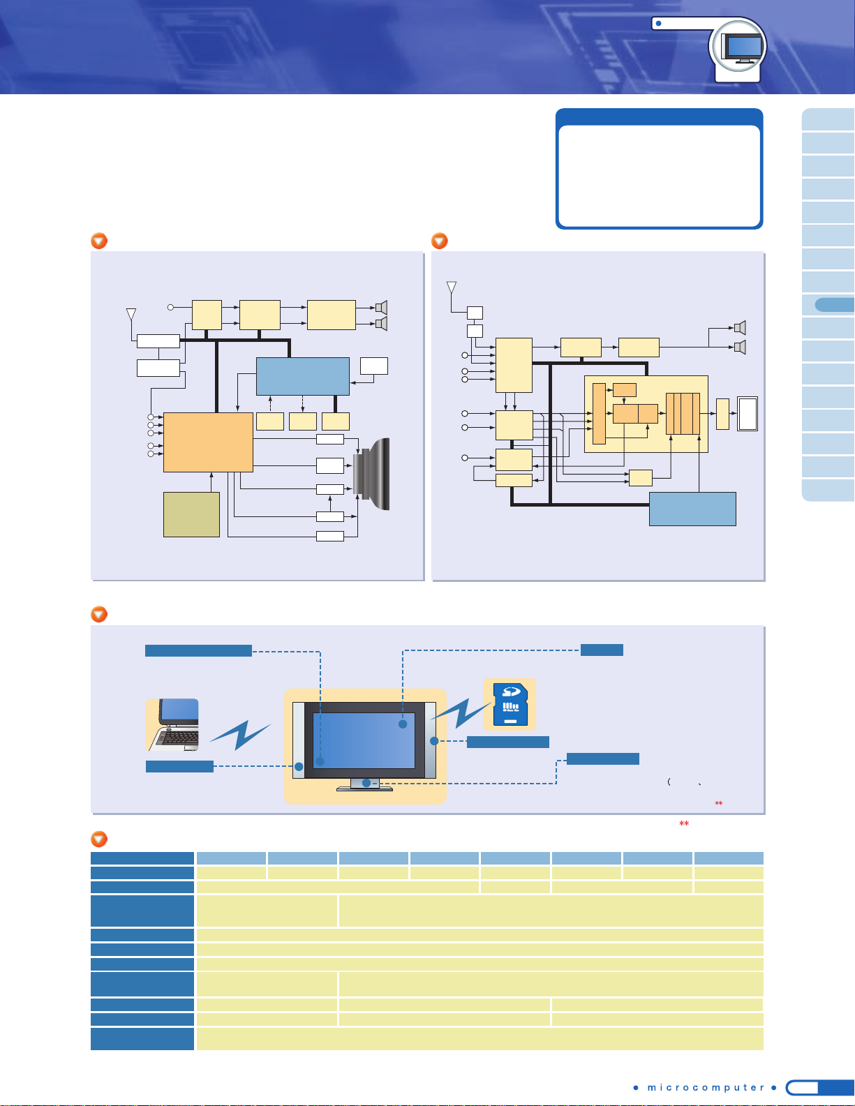
25
● Monochrome font OSD
(in character units)
● Color font OSD (in dot units)
TMP88CS34
TMP88CS38B
Applications
TVs
● Main microcontroller
TMP88CS34
TMP88CS38B
● Sub-microcontroller
AV-Link CEC
, etc.)
TMP86FS49
TMP86FH92
OSD
System control
● Built-in closed-caption decoder
TMP88CS38
TMP88CS38B
● USB1.1
TMP92CH21
● NANDF controller
TMP92CH21
TMP92CA25
For U.S. closed caption
PC interface
Memory access
● UART
TMP91CW12A
TMP91CU27
TMP88CS34NG/FG
*
For details of the products listed above, see the "Part Number List".
Note: Although there is only one channel, the circuit has two sets of input/output lines, which can be selected.
Tuner
LCD
TV-A
L/R out
R-ch
L-ch
AV SW
TC90L01N
Comp SW
Freq. Det.
TB1305FG
YUV-RGB SW
Main MCU
TMP88CS38/34
Surround
TA1343N
D-Class
TB29xxF
TC90200FG
Teletext
TV-V
V1/Y
C
YPbPr CVBS/Y
3L
YCS
Multi
Color
Decoder
RGB
Mix
SW/ADC
Scaler
Picture Control
OSD Mix
Cutoff & Drive
LVDS
Clamp Pulse
Y/Pb/Pr or R/G/B
I
2
C BUS
H/V
ADC
OSD
RGB
CVBS
C
R/G/B
YCbCr
R/G/B1
R/G/B2
CCVBS/Y
Audio IN
AV IN
HD-STB
DVD/PC
SCART
I/F
● High-functionality 8-bit core
(870/X Series)
● High ROM and RAM capacity
●
High-speed operation,
low power consumption
● Serial interface: I2C bus
For color TV applications Toshiba offers a line-up of 8-bit microcontrollers with an OSD function and an I2C bus interface circuit.
■ Microcontrollers for televisions
Part Number
ROM (bytes)
48K
TMP88CP34NG/FG
RAM (bytes)
1.5K
On Screen Display
Dot coloring character
32-digit x 12-line display
OSD clock
External LC oscillation circuit
Packages
AD Converter
I
2
C Interface
PWM
14-bit x 2ch,
12-bit x 2ch,
64K 32K
For U.S. closed caption
32-digit x 12-line display
32K
1.5K
1ch
Note 1)
48K
Internal oscillation circuit
48K
External LC oscillation circuit
64K
2K
SDIP42/QFP44
(
14
x
14 mm
)
8-bit x 6ch
14-bit x 2ch,
12-bit x 2ch,
7-bit x 6ch
64K
2K
I/O
33
Version with OTP
TMP88PS34NG/FG TMP88PS38NG/FG TMP88PS38BNG/BFG
TMP88CM38ANG/AF TMP88CM38BNG/BFGTMP88CP38ANG/AF TMP88CP38BNG/BFGTMP88CS38NG/FG TMP88CS38BNG/BFG
: Under development
Main functions
OSD
Tuner
PIF/SIF
TA1303BFN
Remote
Control
Audio AMP
Main MCU
TB2924FG
TMP88CS34F
CRT
Video processor
from DTV
option module
/HDMI
TC90801MFG
I2C BUS
I
2
C BUS
ITU-R601/656
Panel
Key
Power
Control
EEPROM
VM
H-OUT
E/W
V-OUT
RGB
DRV
Audio
TV
CVBS
Y/C
YPbPr
PC
Audio
Switch
Audio
Processor
TA1343N
CRT TV System block diagram
LCD TV System block diagram
Product outline
Product line-up

26
Applications
Digital equipment
Printers
Network equipment
TMPR4955CFG-400
400MHz/SysAD bus
Part Number Package Additional functions
Part Number Package Additional functions
QFP240
●
32-bit RISC processor ● Built-in instruction cache 8 Kbytes, data cache 4 Kbytes
●
PCI controller, memory controller, DMA controller, timer, serial, etc.
●
Power supply voltage (I/O 3.3 V, internal 2.5 V) ● Operating frequency 133 MHz
QFP160
(4955)
PFBGA217
(4956)
●
64-bit RISC processor ● Built-in instruction cache 32 Kbytes, data cache 32 Kbytes
●
Built-in FPU conforming to IEEE754 (single precision/double precision)
●
Employs 32-bit (
TMPR4955B/C
)/64-bit (
TMPR4956
) SysAD Bus interface
●
Power supply voltage (I/O 3.3 V, internal 1.5 V; TMPR4955B), (I/O 2.5 V or 3.3 V, internal 1.25 V; TMPR4955C,TMPR4956)
●
Operating frequency 200 MHz/300 MHz (TMPR4955B), 400 MHz (TMPR4955C,TMPR4956)
TMPR3927CF
TMPR4956CXBG-400
TMPR4955CFG-400
TMPR4955BFG-200/300
PBGA256
●
64-bit RISC processor ● Built-in instruction cache 16 Kbytes, data cache 16 Kbytes
●
Built-in FPU conforming to IEEE754 (single precision/double precision)
●
NAND Flash controller, PCI controller, DMA controller, memory controller, timer, serial, AC-link, Data Encryption
Standard
(TMPR4926)
, etc. ● Power supply voltage (I/O 3.3 V, internal 1.5 V) ● Operating frequency 200 MHz
TMPR4925XBG-200
TMPR4926XBG-200
PBGA484
●
64-bit RISC processor ● Built-in instruction cache 32 Kbytes, data cache 32 Kbytes
●
Built-in FPU conforming to IEEE754 (single precision/double precision)
●
Memory controller, DMA controller, timer, serial, AC-link,
Ether MAC (TMPR4938), etc.
●
Power supply voltage (I/O 3.3 V, internal 1.5 V)
●
Operating frequency 300 MHz/333 MHz.
TMPR4937XBG-300/333
TMPR4938XBG-300/333
TX4939XBG-400
PBGA456
●
64-bit RISC processor ● Built-in instruction cache 32 Kbytes, data cache 32 Kbytes
●
Built-in FPU conforming to IEEE754 (single precision/double precision)
●
Encryption engine (DES, 3DES, AES etc.), DDR-SDRAM controller, AC-Link,
10/100 BASE-T EtherMAC (2 channels), ATA-100 (2 channels), ITU656 video output port, PCI controller, etc.
●
Power supply voltage (I/O 3.3 V, Internal 1.25 V, DDR-SDRAM 2.5 V (333 MHz or less)/2.6 V (400 MHz))
●
Operating frequency 400 MHz
TX9956XBG-533/600 PBGA272
●
64-bit Superscalar RISC processor ● Built-in instruction cache 32 Kbytes, data cache 32 Kbytes
●
256 Kbyte level 2 cache ● Built in FPU conforming to IEEE754 (single precision/double precision)
●
Employs 32-bit/64-bit SysAD Bus interface ● Power supply voltage (I/O 2.5 V or 3.3 V, internal 1.25 V)
●
Operating frequency 533 MHz/600 MHz
*
For details of the products listed above, see the "Part Number List".
✽✽
: Under development
TC86C001FG
(GOKU-S)
LQFP144
●
PCI/IF (32-bit, 33 MHz)
● ATA/ATAPI host controller, Ultra DMA transfer (mode 4),
maximum transfer rate 66 Mbytes/s
●
USB1.1 host, controller 2 ports (OpenHCI 1.0a supported)
●
USB device controller 1 port
● I2C bus/SIO ● Power supply voltage (I/O 3.3 V, internal 1.5 V)
*
For details of the products listed above, see the "Part Number List".
TX System RISC,
PCI bus products
TX System RISC,
SysAD bus products
TXxxxx
600MHz/PCI-66MHz
TMPR4956CXBG-400
400MHz/SysAD bus
TX9956XBG-533/600
533/666MHz/SysAD bus
TMPR4937XBG-300/333
300/333MHz/PCI-66MHz
TMPR4938XBG-300/333
300/333MHz/PCI-66MHz
TX4939XBG-400
400MHz/PCI-66MHz
TMPR4925XBG-200
200MHz/PCI-33MHz
TMPR4926XBG-200
200MHz/PCI-33MHz
Performance
TMPR4955BFG-200/300
200/300MHz/SysAD bus
TMPR4955AFG-200B
200MHz/SysAD bus
TMPR4951BFG-200
200MHz/SysAD bus
TMPR3927CF
133MHz/PCI-33MHz
TMPR4927ATB-200
200MHz/PCI-66MHz
LQFP100
●
64-bit RISC processor ● Built-in instruction cache 16 Kbytes, data cache 8 Kbytes
●
No FPU ● Employs 32-bit SysAD Bus interface
●
Power supply voltage (I/O 2.5 V or 3.3 V, internal 1.5 V) ● Operating frequency: 200 MHz
TMPR4951BFG-200
These 32- and 64-bit microprocessors are ideal for use as the main controller in digital equipment, such as printers and
network equipment. The units with a built-in PCI bus interface are outstanding for peripheral equipment expandability.
These microprocessors are also useful in other applications.
■ Microprocessors for digital equipment
PCI
Connectuon companion chip
32-/64-bit RISC processors
Microcontrollers Listed by Function / Application
In mass production
Under development

27
Applications
Automotive
SunroofSteering switches
Wipers
8-bit
16-bit
32-bit
Electromotive
power steering
Air bags
Meters
Lights
Mirrors
Compressor
Air conditioner
Display panel
Blower motor
Body control
Keyless entry system
Door switches
Power windows
Note: For details about the automotive grade
products, please contact your local Toshiba
sales representive.
28-/30-pin 64-pin44-pin 100-pin
4 K
8 K
16 K
32 K
60/64 K
48 K
96 K
256 K
512 K
ROM
size
Toshiba offers a wide selection of automotive microcontrollers with various communications functions such as CAN and SEI. These microcontrollers are manufactured to Toshiba's exacting automotiv e g rade standards
Note)
to ensure high quality in a wide range of operating tempera-
tures.
■ Microcomputers for automotive applications
Product line-up for automotive
SOP/SDIP/SSOP
LQFP
(
10 X 10mm
)
/
QFP
(
14 X 14mm
)
LQFP44
(
10 X 10mm
)
LQFP
(
14 X 14mm
)
● CAN
● SEI
Main functions
Immobilizer
Seat position
Passenger
detection
Power seats
86C407I/S
86C807I/S
88CH40I
PMD
86CH92I/S
86FH92I
86C808I/S
86C408I/S
86C892I/S
86CH47I/S 87CH48I/S
86FS49AI
91CU27R
86CH87R
88CH41I/S
86CM87R
86C847I/S
PMD
CAN
CAN
91CP82T
91CY22I
CAN
92CD54I
CAN
92FD54AI
CAN
PWM
: In mass production
: Under development
: Under planning
SOP/QFP
DIP

28
Applications
Automotive
Microcontrollers Listed by Function / Application
TMP86C407I/S
TMP86C807I/S
Part Number
4/8
ROM (bytes)
256
RAM (bytes)
22
I/O
-
CAN
1ch
SEI
-
SIO
1ch
UART
-
I2C
8-bit x 6ch
AD converter
2ch
8-bit timer counter
1ch
16-bit timer counter
Dual Clocks
TMP86P807
OTP/Flash Version
SOP28/SDIP28
Watchdog timer
TMP86C408I/S
TMP86C808I/S
4/8
256
24
-
1ch
-
1ch
-
8-bit x 6ch
2ch
1ch
TMP86P808
SSOP30
TMP86C847I/S
TMP86CH47I/S
8/16
512
35
-
1ch
1ch
-
10-bit x 8ch
2ch
1ch
TMP86PM47A/PH47/FH47A
LQFP44(10 x 10mm)
TMP86CH87R
TMP86CM87R
16/32
1K
35
1ch
1ch
-
1ch
-
10-bit x 14ch
2ch
1ch
TMP86PM87R
LQFP44(10 x 10mm)
Package
Part Number
ROM (bytes)
RAM (bytes)
I/O
CAN(4 mail boxes)
SEI
SIO
UART
I
2
C
I
2
C/UART
AD converter
8-bit timer counter
16-bit timer counter
Motor controller
Dual Clocks
OTP/Flash Version
Watchdog timer
Package
ROM (bytes)
RAM (bytes)
I/O
CAN(16 mail boxes)
SEI
SIO/UART
I
2
C
AD converter
8-bit timer counter
16-bit timer counter
32-kHz timer (for S/W RTC)
Dual Clocks
OTP/Flash Version
Watchdog timer
Package
TMP86C892I/S++
TMP86CH92I/S++
8/16
512
24
-
1ch
-
1ch
-
10-bit x 6ch
2ch
1ch
TMP86FH92I
SSOP30
TMP88CH40I
16
512
19
-
1ch
1ch
-
10-bit x 4ch
2ch
1ch
TMP88PH40
SOP28
-
TMP88CH41I/S++
16
512
19/33
-
1ch
1ch
-
10-bit x 8ch
2ch
2ch
TMP88PH41
LQFP44(10 x 10mm)
-
TMP86FS49AI
60
2K
56
-
2ch
2ch
1ch - - -
1ch
10-bit x 16ch
4ch
2ch
- 1ch 1ch -
-
LQFP64(10 x 10mm)/QFP64(14 x 14mm)
TMP91CP82T
Part Number
48
2K
80
1ch
1ch
2ch
-
10-bit x 12ch
4ch
2ch
-
4ch
-
-
-
-
1ch
16-bit PWM timer
CS/WAIT
controller
H/W RTC
PDC
TMP91PP82T
LQFP100(14 x 14mm)
TMP91CU27R
96
10K
53
-
2ch
1ch
10-bit x 4ch
6ch
1ch
-
3ch
-
-
TMP91FY27
LQFP64(10 x 10mm)
TMP91CY22I
256
16K
81
-
2ch
1ch
10-bit x 8ch
8ch
2ch
-
4ch
-
-
TMP91FY42
LQFP100(14 x 14mm)
TMP92CD54I
512
32K
68
1ch
1ch
2ch
3ch
10-bit x 12ch
8ch
2ch
-
-
1ch
-
TMP92FD54AI
LQFP100(14 x 14mm)
8-bit microcontrollers for automotive
16-bit microcontrollers for automotive
32-bit microcontrollers
for automotive
: Under development
: Under development
: Under planning

29
Applications
Automotive
MOS-FET
Motor predriver (TB9065F)
System power supply
(5V-Reg, reset circuit, WDT,
low voltage detection)
Predriver
LIN transceiver
Comparator
Operational
amplifier
Microcontroller
Watch
dog
timer
ROM
RAM
10-bit
AD
Timer/
counter
I/O
870/X
CORE
SCI
Programmable
motor driver
(sine wave control)
M
Part Number
Series name
870/X 870/X
TMP88CH40IMG TMP88CH41UG
(Note2)
Motor control circuit (PMD)
(Note1)
1ch 1ch
AD converter
10-bit x 4ch 10-bit x 8ch
Memory (ROM/RAM)
16KB/512B 16KB/512B
Package
SOP28
Part Number
DSP
16-bit fixed-point
TMP77CM70TUG
Motor control circuit (PMD)
(Note1)
1ch
AD converter
10-bit x 8ch
Memory (ROM/RAM)
32KB/1KB
Package
LQFP64QFP44
OTP product
(Note3)
TMP88PH40MG TMP88PH41UG
These microcontrollers incorporate an inverter control function for
sensorless/sensor-equipped 3-phase DC and AC motors and a sine
wave drive circuit for supporting high reliability and high temperature
operation. The sine wave drive circuit enables easy sine wave drive
suited to high efficiency and low noise.
■ Microcontrollers for automotive motor control
Note 1: Programmable Motor Driver
Note 2: Automotive-grade products under consideration
Note 3: Standard grade
* For details of the products listed above, see the "Part Number List".
Microcontrollers DSP
Achieved intelligent, high value-added automotive motors!
Blower motor
(low noise)
Water pump
(long life,
high efficiency)
Electromotive fan motor
(long life,
high efficiency)
EPS motor
(low noise,
low vibration)
Automotive motor system block diagram
Product line-up
● Sine wave drive circuit
● Rotor position detection function
●
Motor control timer and timer capture
●
PWM waveform generation function
● Overload protection function
● Abnormality protection function
● Automatic commutation start and
automatic position detection start
Main functions
: Under development

30
Microcontrollers Listed by Function / Application
Applications
TLP3616
TLP3616
TLP3616
2SK3868 × 6 / MP6622
Heater
SIO
Driver IC
TD62304AP
Coupler
TLP421
SW power supply
C.R.F. indoor fan
Motor dumper
Stepping motor driver IC
TA7774P/F
Reset IC
TA8000S
DC motor
driver IC
TA7291P
DC motor
driver IC
TA7288P
Sensor input
Door SW input
EEPROM
Fan motor driver IC
TA84006F
Three-way valve
for 2-evaporator
switching
AC
100V
Surge
absorber
Buzzer output
● Quick freezing
● Quick refrigeration
● Quick defrosting
Key input
Operation panel control
microcontroller
TMP86CX29
Compressor control microcontroller
TMP88CH41/T5BE2
● Inverter output frequency control
● 3-phase PWM waveform synthesis function
LCD display
Control block
Display block
Driver
Refrigeration cycle control
Cooling fan
Compressor fan
Defrosting
Timer control
Open door detection
Ice maker control
Main control microcontroller
TMP86CX49
●
●
●
●
Defrosting
heater
Indoor lamp
Compressor
Automatic
ice maker
LED
output
●
●
●
●
TMP86CX49
4 diodes
TA8000S
TD62003A
Indoor unit
Operation command
Operation information
EEPROM
(Data control)
Partial circuit
Louver motor drive circuit
Louver
motor
Transistor array
Compressor
Restart delay function
Indoor fan
Startup compensation function
Temperature computation
function
Outdoor unit
Operation command function
● Transformer
● Power regulation circuit
Operating mode display
Power level display
Remote
control
Indoor fan drive circuit
DC indoor
fan motor
LED
TB6520P + TA8483CP
TMP88FW45/TMP19A71
TLP351
GT15J321 x 6
TLP351
2SK3868
Overcurrent protection
function
Frequency control
Compressor
Restart delay function
Temperature computation function
Inverter control
Outdoor DC fan
RPM control
Compressor
Outdoor unit
Power supply
Driver coupler
D-IGBT
TLP3502/3503
AC power coupler
Fan
motor
Driver coupler
MOS FET
Temperature sensor
(room temperature/
radiant heat/heat exchanger)
TMP86CX25
● Power ON/OFF
● Operating mode change
(for comfortable sleeping/normal)
● Cooling/heating switching
(Cooling/heating/dehumidifying)
● Temperature setting
● Timer/clock setting
● Fan power
●
●
●
●
●
●
Two-way/four-way valve
RefrigeratorsAir conditioners
■ Microcontrollers for inverter electric appliances
The following microcontrollers incorporate various functions suitable for
electric appliances that require user interfaces, sensor inputs, actuator control,
and communications.
● AD converter
● Serial communication
● Motor control circuit
● LCD driver
Main functions
Air conditioner system block diagram
Refrigerator system block diagram
Product outline
*
Some of the flash memories use the SuperFlash® technology under the license of Silicon Storage Technology, Inc. SuperFlash® is a registered trademark of Silicon Storage Technology, Inc.
TMP86CH21A
TMP86CS28
TMP86C822
TMP86CH22
TMP86CP27A
TMP86CM27
TMP86C822
TMP86CH22
TMP86CS28
Panel
● LCD driver
● Serial communication
TMP86C829B
TMP86CH29B
TMP86CM29B
TMP86C420
TMP86C820
Indoor unit
● AD converter for sensor input
●
Serial communication with outdoor unit
● I/O for controlling actuators
Outdoor unit
● Motor control circuit
● AD converter for sensor input
●
Serial communication with outdoor unit
Remote control
● LCD driver
● Key input
Main control block
● Brushless DC motor control circuit
● AD converter for sensor input
● Serial communication
TMP86CS49
Inverter control block
● Motor control circuit
● AD converter for sensor input
T5BE2 TMP88CH41
TMP88CS43 TMP19A71CY
TMP88CS42 TMP88FW44
TMP88FW45
TMP86CH49 TMP86CS49
TMP86CM49 TMP91FW60
TMP86CM25A
TMP86CM25
TMP86CS25A
TMP86C829B
TMP86CH29B
TMP86CM29B
TMP86CM29L
TMP86C420
TMP86C820

31
Applications
LCD display
TMP86C420
TMP86C820
TMP86C822
TMP86C829B
TMP86CH21A
TMP86CH22
TMP86CH29B
TMP86CM23A
TMP86CM29
TMP86CM25
AF control (computation),
AE control (computation)
Built-in strobe control
Dial input, shutter control
TMP1942CYU
TMP1942CZU
TMP1942CZXB
Camera control/Shutter control
AF control/Tape control
TMP1962C10BXB
TMP19A64F20BXB
TMP19A64C1DXB
TMP19A43FDXB
TMP19A43FZXB
TMP19A43CDXB
TMP19A43CZXB
TMP86FM26
TMP86CP23A
TMP86FP24
TMP86CS25A
TMP86CS28
TMP86FS28
These microcontrollers incorporate high-speed AD converters to support
AF/AE control (computation), dial input, and other features suitable for the
main controller of a single-lens reflex camera.
■
Microcontrollers for digital single-lens reflex cameras (DSLRs)
These microcontrollers, responsible for controlling the camera and tape deck
sections, contain large-capacity ROM to help minimizing the product size and
support various features suitable for main DVC control.
■ Microcontrollers for digital video cameras (DVCs)
LENS
Zoom
Motor
EEPROM
Large-scale software
that controls the camera
and deck blocks.
Multipin system control
interface
High performance,
low power dissipation
A single chip controls
both the camera and
deck blocks.
Analog Font End
Camera
DSP
Memory Card
USB
IEEE1394
In-out
LCD panelLCDC
OPAMP
Motor
Drive
DECK
System
microcontroller
TMP1962
TMP19A64
Flash Key
Audio
DV control
LSI
Video
Image processing system
Timing signal
AF control
Shutter control
Iris control
Signals
Camera control system
Analog
front
end
USB
IEEE1394
Wireless,
infrared ray
Battery control
AE
Sensor
AF
Sensor
DRAM
Camera
Key/switch
Information display LCD
LCD
microcontroller
Memory
card
Lens
micro-
controller
Image display
LCD
System
microcontroller
DSC signal
processing
LSI
(CUSTOM)
SoC
For image processing engine
For display system
For main processing in camera control system
TLCS-870/C
Area
Sensor
TMP1942
TMP19A43
Independent image processing
and camera control systems
run in parallel.
Faster image processing
High-speed multipoint AF
DVCs DSLRs
Part Number
Maximum operating frequency (MHz)
32
TMP1942CYUG/CZUG/CZXBG
Internal bus width
32
External bus width
16 (address/data
multiplexed)
Internal ROM (bytes)
256/384K
Internal RAM (bytes)
16K
DMAC channels
4ch
I/O ports
108
Serial interface
6ch
Timer channels
28ch
External interrupt pins
29
Dual clock
●
Debug support unit
● (Flash product only)
Package
LQFP144(16 x 16mm)/
FBGA177(13 x 13mm)
40.5
Supply voltage (V)
2.7 to 3.6
1.35 to 1.65
I/O: 1.65 to 3.3
2.3 to 3.3
AD: 2.7 to 3.5
TMP1962C10BXBG
32
16
(multiplexed or
separate selectable)
1024K
AD converter 16ch (conversion time: 2µs)
24ch
40K
8ch
202
8ch
18ch
25
●
FBGA281(13 x 13mm)
Others
10-bit DA converter x 3 channels
ROM correction
2-phase pulse input counter
Dynamic pull-up
5 V capable ports (x 15)
ROM correction
2-phase pulse input counter
-
40
1.35 to 1.65
I/O, AD
:
2.7 to 3.6
DA
:
2.3 to 2.7
TMP19A43FDXBG/CDXBG
32
16
(multiplexed or
separate selectable)
512K
16ch (conversion time: 1.15µs)
24K
8ch
143
7ch
17ch
48
●
FBGA193(12 x 12mm)
8-bit DA converter x 2 channels
ROM correction
2-phase pulse input counter
Dynamic pull-up
●
40
1.35 to 1.65
I/O, AD
:
2.7 to 3.6
DA
:
2.3 to 2.7
TMP19A43FZXBG /CZXBG
32
16
(multiplexed or
separate selectable)
384K
16ch (conversion time: 1.15µs)
20K
8ch
143
7ch
17ch
48
●
FBGA193(12 x 12mm)
8-bit DA converter x 2 channels
ROM correction
2-phase pulse input counter
Dynamic pull-up
●
54
1.35 to 1.65
I/O: 1.65 to 3.3
TMP19A64F20BXBG/C1DXBG
32
16 (multiplexed or
separate selectable)
2048K/1536K
24ch
64K/56K
8ch
209
8ch
12ch
20
●
FBGA281(13 x 13mm)
Built-in back-up block
ROM correction
2-phase pulse input counter
●
*
For details of the products listed above, see the "Part Number List".
: Under development
: Under development
● AF/AE control
(high-speed AD/multidigit operation)
● Dial input control
● Shutter control
● Tape control
● LCD display control
Main functions
Product line-up
Product outline
DVC system block diagram
DSLR system block diagram

32
Microcontrollers Listed by Function / Application
CD
Mechanism
and PUH
Analog out
* MP3 and WMA are trademarks or registered trademarks of their respective holders.
CD-MP3
Decoder
Control
SPI
USB
Bit Stream
I/F
SIO/UART/I
2
C
SD Memory
Card
USB Memory
Motor Driver
Main MCU
USB Host
CD-MP3 Decoder
TC94A70
USB MCU
TMP92FD28
Main MCU
TMP92CY23
TMP92CD23A
TMP92CD54I
PIO
SW, Volume Control
SCI
Remote control
Sensor
Analog SW E-Volume
RDS
AMP
Tuner Unit, PLL
MD Unit
CD Unit, changer
MCU driver
for display
SCI
RDS Unit Control
Tuner Unit Control
SCI
MD Unit Control
SCI
CD Unit Control
SCI, CAN
SCI, BUS
Display Control
Sensor Input
MP3
Decoder
CD
Servo
Applications
Audio systems Car audios
CD-MP3 control MCU
Toshiba's extensive line-up of microcontrollers for audio applications includes
16-bit products ideal for controlling CD-MP3 decoder ICs, and 32-bit products
incorporating a USB host controller which are software-compatible with the
16-bit products.
■ Microcontrollers for audio (CD-MP3 control MCUs)
16-bit core
TLCS-900/L1
Series
32-bit core
TLCS-900/H1
Series
USB host controller built in
100-pin
100-pin
128KB/4KB
ROM/RAM expanded
These 32-bit microcontrollers incorporate large-capacity memory and a wide
range of serial interfaces, hence they are suitable for main control, for
example, in car audio. The series also includes products that contain CAN
controllers.
■ Microcontrollers for audio (Main control MCUs)
Part Number
Series name 900/L1
TMP91CP27UG/
TMP91CU27UG
ROM(bytes) 48KB/96KB
RAM(bytes) 4KB/10KB
I/O port 53
10-bit AD converter(ch)
4ch
UART/SIO (ch) 2ch
I2C bus/SIO (ch) 1ch
USB HOST controller
Packag e LQFP64
Main control MCU
Part Number
Series name 900/H1
TMP92CY23FG/DFG
ROM(bytes) 256KB
RAM(bytes) 16KB
I/O port 84
10-bit AD converter(ch)
12ch
UART/SIO (ch) 3ch
I2C bus/SIO (ch) 2ch
CAN
Packag e LQFP100/QFP100
900/H1
TMP92CD54IFG
512KB
32KB
68
12ch
2ch
3ch
1ch
QFP100
900/H1
TMP92CD23AFG/DFG
512KB
32KB
84
12ch
3ch
2ch
LQFP100/QFP100
900/L1
TMP91CW12AFG/
TMP91CY22FG
128KB/256KB
4KB/16KB
81
8ch
2ch
1ch
LQFP100
900/H1
TMP92CY23FG/DFG
TMP92CD23AFG/DFG
256KB/512KB
16KB/32KB
84
12ch
3ch
2ch
LQFP100/QFP100
900/H1
TMP92CD28FG/
TMP92CD28DFG
512KB
32KB
72
2ch
2ch
1ch
LQFP100/QFP100
● Controlling CD servo and
CD-MP3 decoder ICs
● Memory variations
● Pin count variations
Main functions
● High performance
● Large-capacity memory
● Range of serial interfaces
● Peripheral unit control
Main functions
Sample application: CD-MP3/USB/SD system
Sample application : Main control system
Product line-up
Roadmap for audio MCUs
TMP91CW12A
100-pin
256KB/16KB
512KB/32KB
TMP91CY22
100-pin
256KB/16KB
High speed,
high functionality
Smaller
ROM/RAM,
lower pin
count
TMP91FY42
64-pin
48KB/4KB
TMP91CP27
64-pin
96KB/10KB
Pin count
ROM size/RAM
size
TMP91CU27
64-pin
128KB/12KB
TMP91FW27
64-pin
256KB/16KB
TMP91FY27
TMP92CD28
TMP92FD28
100-pin
256KB/16KB
TMP92CY23
TMP92FY23
100-pin
512KB/32KB
TMP92CD23A
TMP92FD23A
: Under development
: Under development : Under development
: Flash ROM
: Mask ROM
*
Some of the flash memories use the SuperFlash® technology under the license of Silicon Storage Technology, Inc. SuperFlash® is a registered trademark of Silicon Storage Technology, Inc.

33
64-bit
superscalar
64-bit core
32-bit core
32-bit core
MIPS64 &
MIPS-3D ASE
MIPS
MIPS
MIPS & MIPS16
✽ These are original cores developed independently
by Toshiba based on each MIPS architecture.
For fields requiring higher functionality and
performance in network connection
TX99
A 64-bit core ideal for digital equipment that
requires high performance.
TX49
Balanced cost/performance. A variety of
applications ranging from commercial to
industrial equipment
TX39
Ideal for products such as mobile equipment
where the focus is power consumption, cost
and code efficiency
TX19
TX39
TX99
TX49
TX19
TX39
TX19
TX99
TX49
Higher performance
levels
Lower-cost design and
lower-power consumption
Digital networks,
automotive
(digital information)
Networks, LBP,
Digital information
appliances, DSCs
Mobile terminals,
networks,
car navigation
Cameras, automotive
devices, DSCs, DVCs,
DVDs, HDDs
Seamless core
TX System RISC
line-up
A complete line-up of products, ranging from low-power-consumption devices to
high-speed-processing devices, to suit a wide variety of applications
Performance
RISC stands for Reduced Instruction Set Computer. The smaller, fixed-length instruction set of a RISC processor
allows fast program execution. Compared to the conventional CISC (Complex Instruction Set Computer), the RISC
processor's simplified circuit structure offers attractive features such as increased execution speed and reduced power
consumption.
Toshiba has adopted the RISC processor technology developed by MIPS Technologies, Inc. In addition to the 32-bit
processor TX39 Family for embedded use, Toshiba has also developed the TX19 Family of processors, featuring an
additional 16-bit instruction set, and the 64-bit TX49 and TX99 Family of processors for embedded use. The TX19,
TX39, TX49 and TX99 families serve as CPU cores, which, together with megacells for peripherals, offer solutions for
the implementation of ASICs.

34
TX9956XBG-533/600
Superscalar Architecture
TX99 Processor Core Features
The TX99 Family of RISC microprocessors is based on the MIPS64TM microarchitecture of MIPS Technologies, Inc.
(U.S.A.) These microprocessors have a 64-bit superscalar architecture developed jointly by MIPS and Toshiba.
MIPS64
TM
has the highest performance in the industry, enabling simultaneous execution of two instructions. By using
this architecture in semiconductors and systems, it is possible to achieve high-speed data processing in fields such
as automotive (digital information), OA, home servers, digital information appliances and networks where cost and
power consumption are the top priority.
TX99
Family
64-Bit Superscalar TX System RISC
Can be used as a CPU core for custom SoC
Under
development
Based on MIPS 25Kf high-end RISC core
Instruction set: MIPS 64
TM
with MIPS-3DTM ASE
Employs dual issue superscalar pipeline (7-stage)
Core operation frequency: 533 MHz/600 MHz
Equipped with 32-Kbyte instruction cache and
32-Kbyte data cache
employs 4-way set-associative system
Level 2 cache of up to 256 Kbytes can be installed
(optional)
Built-in single/double precision floating point coprocessor
SOC I/F with a high bus band width (12.8 Gbytes/s)
with numerous bus frequency division ratios for core
vs. SOC I/F
TX99/H4: 90-nm process technology
Complete development environment
64-bit RISC microprocessor using a Superscalar architecture
● 64-bit Superscaler equipped with
TX99/H4 core
● On-chip caching
Four-way set-associative caches
Instruction cache: 32 Kbytes
Data cache: 32 Kbytes
Level 2 cache: 256 Kbytes
● External bus (SysAD bus)
64-/32-bit
● Single-/double-precision FPU
● Clock generator (CG)
● Low power consumption mode
● Built-in debug support unit (DSU)
● Maximum operating frequency:
Core: 533 MHz/600 MHz
External bus: 133 MHz
● I/O operating voltage: 2.5 V or 3.3 V
Internal operating voltage: 1.25 V
● Package:
272-pin PBGA, 27 mm x 27 mm,
1.27-mm pitch (with 16 thermal balls)
The TX9956XBG is equipped with a TX99/H4 core that uses a 90 nm
process to enable 533 or 600 MHz operation. This processor has a
built-in floating-point unit (FPU) and SysAD bus interface, and is useful
in a wide range of applications areas including LBPs and set-top
boxes. It contains 32-Kbyte instruction cache and 32-Kbyte data cache,
as well as large secondary cache of 256 Kbytes.
TX99/H4 Core
Integer Arithmetic
Unit
256-Kbyte Level 2 Cache
System Control
Coprocessor
Coprocessor
Registers
Memory Management Unit
48 Double-Entry TLB
Exception Handling Unit
Floating-Point
Unit
Coprocessor
Floating-Point
Unit
Registers
Floating-Point
Unit Data
Path Logic
32-KB 4-Way
Set-Associative
Instruction Cache
64-Bit
GeneralPurpose
Registers
Dual
Issue
Pipeline
Control
Integer
Arithmetic
Data Path
Logic
MAC Unit
32-KB 4-Way
Set-Associative
Data Cache
Cache Controller
Write
buffer
Clock
Generator
Debug
Support Unit
(EJTAG)
SysAD
Bus
Interface
MGB II Bus
MGB II Bus
SysAD Bus Interface

35
The TX49 Family of RISC microprocessors for embedded use is an original Toshiba 64-bit processor family and is
based on the RISC architecture designed by MIPS Technologies, Inc. The customer can implement a custom SoC using the TX49 Family cores in conjunction with general-purpose ASSP products.
TMPR4951BFG-200
First product incorporating the TX49/L3 core
TX49
Family
64-Bit TX System RISC
64-bit RISC architecture Low-power consumption design
Built-in high-capacity primary cache
Can be used as a CPU core for custom SoC
● Instruction cache: 32 Kbytes
■
4-way set-associative
■
Lock function supported
● Data cache: 32 Kbytes
■
4-way set-associative
■
Lock function supported
■
Write-back/write-through (every page)
●
Low-power consumption modes (Doze/Halt)
● TX49/H2: 0.18-µm process technology
● TX49/H3, TX49/L3: 0.13-µm process technology
● TX49/H4, TX49/L4, TX49/W4: 90-nm process technology
● Complete development environment
● R4000A architecture
■
Upward-compatible instruction set including MIPS I,
MIPS II and MIPS
III
instruction set architectures (ISAs)
● TX49/H2: Internal operating frequency: 200 MHz
● TX49/H3: Internal operating frequency: 300 MHz/333 MHz
● TX49/H4: Internal operating frequency: 400 MHz
● TX49/L3: Internal operating frequency: 200 MHz
● TX49/L4: Internal operating frequency: 333 MHz
(Under development)
● TX49/W4: Internal operating frequency: 400 MHz
(Under development)
■
Level 2 cache of up to 256 Kbytes can be installed (optional)
● Non-blocking load function
■
The instructions which follow the instruction currently
be
ing executed are executed while the cache is being refilled.
● DSP function
● Thirty-two 64-bit general-purpose registers
● Optimized 5-stage pipelining
● Single- or double-precision floating-point unit (FPU)
(TX49/H2, TX49/H3, TX49/H4 and TX49/W4 core)
● Debug support unit (DSU)
■
Supports EJTAG.
64-bit RISC microprocessor offering excellent cost performance
The TMPR4951BFG incor porates a 0.13-µm process TX49/L3 core,
and by minimizing the built-in functions and external interfaces, it offers the industry's highest cost-performance ratio in the 200 MHz
class and low-power consumption, all encapsulated in a compact package. Moreover, the SysAD bus interface adopted for this microprocessor
enables diverted use of existing resources and facilitates system de v elopment. These and other features make it an ideal controller for lowend LBPs, networks, and settop boxes.
● TX49/L3 64-bit RISC core
● Five-stage pipeline
● On-chip caching
4-way set-associative caches
Instruction cache: 16 Kbytes built in
Data cache: 8 Kbytes built in
Cache lock function
● 48 double-entry
● External bus (32-bit SysAD bus)
● Low-power consumption mode
● Debug support unit (DSU) built in
(execution control only)
● Maximum operating frequency:
Core: 200 MHz
External bus: 100 MHz
● I/O supply voltage: 2.5 V or 3.3 V
Internal supply voltage: 1.5 V
● Package: 100-pin LQFP
(14 mm x 14 mm, 0.5-mm pitch)
TX49/L3 Core
Integer Arithmetic
Unit
System Control
Coprocessor
Clock
Generator
64-Bit
GeneralPurpose
Registers
Pipeline
Control
Integer
Arithmetic
Data Path
Multiplier/
Accumulator
Unit
Coprocessor
Registers
Memory Management
Unit
48 Double-Entry TLBs
Exception
Handling Unit
16-KB 4-Way
Set-Associative
Instruction Cache
8-KB 4-Way
Set-Associative
Data Cache
Cache
Controller
Write
Buffer
Sync Circuit
Debug
Support Unit
(EJTAG)
SysAD Bus
Interface

36
TX4939XBG-400
This highly functional, high-performance family contains an encoder, and is well adapted to digital information equipment.
TX49
Family
64-Bit TX System RISC
RTC SIO SPI I2C
AC-Link/
I
2
S
Encoder
DDR-SDRAM
Controller
External Bus Interface
(NAND FLASH)
DMA Controller
10/100BASE-T
EtherMAC
ATA100
Video port
PCI Controller
IM BUS Bridge
TX49/H4 core
Debug Support Unit (DSU)
Data Cache
(32K)
Instruction
Cache (32K)
IU
MMU
BIU
Write
Buffer
Floating-Point Unit (FPU)
G BUS Interface
General
Purpose
Register
MAC unit
64-bit
G-BUS
32-bit IM BUS
64-bit RISC microcontroller with encoder, DDR-SDRAM controller, EtherMAC, and ATA100
The TX4939XBG-400 is based on a TX49/H4 core, and
contains an encoder, a DDR-SDRAM controller, an
ATA100, an EtherMAC, a PCI controller and other peripherals. It is a highly functional, high-performance, 64-bit RISC
microcomputer optimally applicable to digital information
appliances. The processor operates at a frequency of 400
MHz, while the PCI bus runs at a frequency of 33/66 MHz.
● TX49/H4 64-bit RISC core
● On-chip caching
4-way set-associative caches
Instruction cache: 32 Kbytes
Data cache: 32 Kbytes
Cache lock function
● Memory management unit
● Memory controller: DDR-SDRAM (32-bit, 400 MHz)
Supports NAND Flash, SRAM, ROM and NOR Flash
● Encoder: Supports DES, 3DES, AES, MD5, SHA1 and
Modular Exponentiation Operation Coprocessor
● DMA controller: 8 channels
● 10/100BASE-T EtherMAC: 2 channels
● ATA100: 2 channels
● Video port: 1-parallel I/O, 3-serial in
● PCI controller: 33/66 MHz
● AC-Link
● I2S
● SIO: 4 channels
● SPI
● I2C
● Interrupt controller
● Maximum operating frequency: 400 MHz
● I/O supply voltage: 3.3 V
Internal supply voltage: 1.25 V
● I/O (DDR 400): 2.6 V
I/O (less or equal to DDR 333): 2.5 V
● Package: 456-pin PBGA (with 36-pin thermal balls)
TX4939 reference board
This board consists of a CPU module and a base board.
CPU module
● TX4939XBG-400
●
Contains four 512 M-bit DDR-SDRAMs suitable for the
DDR400 in the standard configuration sized totally at 256 MB.
●
Contains a power supply necessary to drive the DDR memory.
●
Supports an EJTAG interface that allows data to be read and written.
● Supports a DIP switch used for boot setting.
●
Provided with the CPU around which reset, clock and RTC circuits are installed.
Base board
●
The TX4939 contains two channels of Ethernet controllers each of
which consists of a 10/100M Ethernet MAC and an external PHY.
● Supports a NOR flash ROM (x 16 bits) consisting of 32
MB of a user ROM and 8 MB of a monitor ROM.
● Contains 32 MB of a NAND flash ROM (x 8 bits).
● Supports two channels of ATA (IDE) interfaces.
● Contains an AUDIO (AC-link/I2S) interface.
● Supports five channels of PCI slots.
● Provided with a USB 2.0 host.
● Supports four channels of RS-232C interfaces.
●
Contains a 100 Base-TX Ethernet controller used for debugging.
● Equipped with a ROM emulator connector.
● Supports two ISA slots.
● Contains a connector for external bus extension.
● Provided with an I/O controller.
● Contains a power supply.
● Full size: ATX size
● The model ID required for ordering TX4939 reference
board is RBHMA4700 (CE).
TX4939XBG
(400MHz)
RS-232C
2 channels
DDR SDRAM
256MB
AMR Connector
NOR
FLASH ROM
NAND
FLASH ROM
Ethernet x2
10/100M
IDE Connector
USB 2.0 Host
VT6212
PCI Card Slot
3.3V x3.5V x2
ISA Connector
Ethernet
(100M)
Connector for external bus extension (150 pin)
32-bit
Local Bus (8/16-bit)
PCI Bus

37
TMPR4938XBG-300/333
Built-in PCI controllers, Ether MAC
64-bit RISC microprocessor with built-in PCI controller and Ether MAC
TMPR4955CFG-400 TMPR4956CXBG-400
Achieves 400 MHz operation
The TMPR4938XBG is a 64-bit RISC microprocessor ideal for networks and digital consumer applications. It is based on the TX49/H3
core and has a variety of built-in functions, including PCI controller,
Ether MAC, DMA controller, NAND Flash controller, memory controller, UART and timers. The processor runs at 33/66 MHz, and the PCI
bus at 300/333 MHz.
● 64-bit RISC equipped with TX49/H3 core
● On-chip caching
Four-way set-associative caches
Instruction cache: 32 Kbytes built in
Data cache: 32 Kbytes built in
Cache lock function
● Memory management unit (TLB): 64 entries
4 K / 16 K / 64 K / 256 K / 1 M / 4 Mbyte pages
● Memory controller: SDRAM (64-bit, 133 MHz)
Supports NAND Flash, SRAM, ROM,
NOR Flash and I/O
● Interrupt controller: 6 external sources
● 32-bit timer: 3 channels
● UART: 2 channels
● PCI controller (32-bit, 33/66 MHz)
● DMA controller: 8 channels
● AC-Link (AC97 interface)
● Ether MAC: 2 channels
● I/O ports: 16-bit
● Maximum operating frequency: 300/333 MHz
● I/O supply voltage: 3.3 V
Internal supply voltage: 1.5 V
● Package: 484-pin PBGA
(with 64-pin thermal balls)
TX49/H3 core
Debug Support Unit (DSU)
Data Cache
(32K)
Instruction
Cache (32K)
IU
MMU
BIU
Write
Buffer
Floating-Point Unit (FPU)
G BUS Interface
General
Purpose
Register
MAC unit
64-bit
G-BUS
Clock Generator
NAND Flash Controller
SDRAM Controller
External Bus Interface
DMA Controller
PCI Controller
Ether MAC
IM BUS Bridge
AC-Link
UART Timer Parallel I/O
Interrupt
Controller
64-bit RISC microprocessors that can easily be enhanced with desired functions
The TMPR4955CFG and TMPR4956CXBG are equipped with a
TX49/H4 core that uses a 90-nm process to enable 400 MHz opera-
tion. These processors have a built-in floating point unit (FPU) and
SysAD bus interface, and are useful in a wide range of application
areas including LBP, networks and set-top boxes. A debug support
unit (DSU) is also built in, and this enables real-time PC tracing and
various types of execution control.
● 64-bit RISC equipped with TX49/H4 core
● Five-stage pipeline
● On-chip caching
4-way set-associative caches
Instruction cache: 32 Kbytes built in
Data cache: 32 Kbytes built in
Cache lock function
● 48 double-entry TLB
● External bus (SysAD bus):
32-bit (TMPR4955CFG)
64-/32-bit (TMPR4956CXBG)
● Single-/double-precision FPU
● Low power consumption mode
● Built-in debug support unit (DSU)
● Maximum operating frequency:
Core: 400 MHz
External bus: 133 MHz
● I/O supply voltage: 2.5 V or 3.3 V
Internal supply voltage: 1.25 V
● Package:
160-pin QFP (TMPR4955CFG)
217-pin PFBGA (TMPR4956CXBG)
TX49/H4 Core
Integer Arithmetic
Unit
System Control
Processor
Coprocessor
Registers
Memory Management
Unit (MMU)
48 Double-Entry TLB
Exception
Handling Unit
Floating-Point Unit
Coprocessor
Floating-Point
Unit Registers
Floating-Point
Unit Data Path
Logic
64-Bit
General-
Purpose
Registers
Pipeline
Control
Integer
Arithmetic
Data Path
Logic
MAC
Unit
Clock
Generator
Sync Circuit
Debug
Support Unit
(EJTAG)
32-KB 4-Way
Set-Associative
Instruction Cache
32-KB 4-Way
Set-Associative
Data Cache
Cache
Controller
Write
Buffer
32-Bit
SysAD Bus
Interface

38
The TMPR4937XBG is based on a TX49/H3 core, and contains a
PCI controller, a DMA controller, a memory controller, a UART, a
timer and other peripherals. It is a 64-bit RSC microcomputer well
adapted to networks and digital information appliances. The
processor operates at frequencies of 300 MHz and 333 MHz, while
the PCI bus runs at a frequency of 33/66 MHz.
● TX49/H3 64-bit RISC core
● On-chip caching
Four-way set-associative caches
Instruction cache: 32 Kbytes
Data cache: 32 Kbytes
Cache lock function
● Memory management unit (TLB): 64 entries
4 K / 16 K / 64 K / 256 K / 1 M / 4 Mbyte pages
● Memory controller: SDRAM (64-bit, 133 MHz)
SRAM, ROM, NOR Flash and I/O
● Interrupt controller: 6 external sources
● 32-bit timer: 3 channels
● UART: 2 channels
● PCI controller (32-bit, 33/66 MHz)
● DMA controller: 8 channels
● AC-Link (AC97 interface)
● I/O ports: 16-bit
● Maximum operating frequency: 300/333 MHz
● I/O supply voltage: 3.3 V
Internal supply voltage: 1.5 V
● Package: 484-pin PBGA
(with 64-pin thermal balls)
TX49/H3 core
Debug Support Unit (DSU)
Data Cache
(32K)
Instruction
Cache (32K)
IU
MMU
BIU
Write
Buffer
Floating-Point Unit (FPU)
G BUS Interface
General
Purpose
Register
MAC unit
64-bit
G-BUS
Clock Generator
SDRAM Controller
External Bus Interface
DMA Controller
PCI Controller
IM BUS Bridge
AC-Link
UART Timer Parallel I/O
Interrupt
Controller
TMPR4937XBG-300/333
Built-in PCI controllers
TMPR4926XB-200
Built-in PCI controller, Encoder (DES) and NAND Flash controller
64-bit RISC microprocessor with built-in PCI controller
General-purpose 64-bit RISC microprocessor with NAND Flash controller, PCI, DMA and DES
TX49
Family
64-Bit TX System RISC
The TMPR4926XB-200 is a 64-bit RISC microcomputer that is based
on a TX49/H2 processor core and contains a NAND flash controller,
a PCI controller, a memory controller, a UART, a timer, a DES and
other peripherals. It supports a TX49/H2 core suitable for high-speed
mode. The processor operates at a frequency of 200 MHz, while the
PCI bus runs at a frequency of 33 MHz.
● Instruction cache: 16 Kbytes
(4-way set-associative caches)
● Data cache: 16 Kbytes
(4-way set-associative caches)
● MAC: Multiply-accumulate
● Memory management unit (TLB):
48 double entries (odd/even)
Joint TLB, 4 K/16 K/64 K/256 K/1 M/4 M bytes pages
● Memory controller:
Supports NAND Flash, SDRAM (32-bit, 80 MHz),
SRAM, ROM, NOR Flash and I/O
● Interrupt controller: 8 external sources
● 32-bit timer: 3 channels
● UART: 2 channels
● SPI
● PCI controller (32-bit, 33 MHz)
● DMA controller: 4 channels
● PCMCIA: 2 slots
● AC-Link (AC97 interface)
● Real-time clock
● CHI
●
DES/3DES (Data Encryption Standard: Encoder)
● I/O port: 32-bit
● RF (Reduced Frequency) function
● Maximum operating frequency: 200 MHz
● I/O supply voltage: 3.3 V
Internal supply voltage: 1.5 V
● Package: 256-pin PBGA (27 x 27 mm)
TX49/H2 core
Debug Support Unit (DSU)
Data Cache
(16K)
Instruction
Cache (16K)
IU
MMU
BIU
Write
Buffer
Floating-Point Unit (FPU)
G BUS Interface
General
Purpose
Register
MAC unit
32-bit
G-BUS
AC-Link
UART Timer SPI RTC
Parallel
I/O
Interrupt
Controller
NAND FLASH Controller
SDRAM Controller
External Bus Interface
DMA Controller
PCI Controller
PCMCIA Interface
CHI
Data Encryption Standard
(
DES
)
IM BUS Bridge

39
The TX39 Family of RISC microprocessors for embedded use was developed by Toshiba based on the R3000A architecture designed by MIPS Technologies, Inc. It is an original Toshiba 32-bit processor family. Using the TX39/H or the
high-speed TX39/H2, TX39/H3 as the CPU core for gate arrays and cell-based ICs, you can accomplish a high
level of integration in your system.
TC86C001FG (Goku-S)
PCI-connected companion chip
Companion Chip
High-performance RISC technology
Low power consumption
Functions suitable for embedded applications
Ideal as CPU core in embedded arrays/cell-based ICs
TX39
Family
32-Bit TX System RISC
● PCI interface
32-bit PCI bus (33 MHz)
PCI Rev. 2.2 compatible
● ATA/ATAPI host controller
Single channel: Can connect up to two systems
Ultra ATA/66: Supports 66 Mbytes/s
PIO modes 0 to 4, multiword DMA modes 0, 1, 2
● USB 1.1 host controller
OpenHCI 1.0a compliant
2 ports: 12 Mbits/s or 1.5 Mbits/s
Built-in overcurrent protection circuit (for each port)
● USB device controller
1 port: 12 Mbits/s
● I2C bus/SIO controller
I
2
C master/slave mode
UART
● GPIO: 1 or 5 ports
● Core operating voltage: 1.5 V
Peripheral I/O operating voltage: 3.3 V
● 144-pin LQFP package (20 mm x 20 mm)
Companion chip with built-in ATA and USB interfaces
Companion chip with built-in ATA and USB interfaces
The TC86C001FG (GOKU-S) is a highly integrated,
high-performance interface LSI chip that supports a
widely used five interfaces. It incorporates a PCI
interface, ATA/ATAPI host controller, USB host controller,
USB device controller, I
2
C bus, and serial I/O controller.
The GOKU-S facilitates designing a wide range of digital
products, including set-top boxes, PVR, information
equipment, and multifunction printers.
GOKU-S
(TC86C001)
PCI interface logic
Clock
Generator
ATA/ATAPI
1ch
USB
DEVICE
1ch
USB
HOST
2ch
I
2
C/SIO/
GPIO
G-Bus
8MHz
PCI Local Bus (32bits, 33MHz)
● Reduced code size and improved performance
■
Use of branch-likely instructions
■
Hardware interlock function
● Increased real-time capability
■
Cache lock function
● Real-time debugger system connection
■
Real-time debugging is possible while cache is on.
● Low power consumption modes
● Clock stop function
● TX39/H2: 0.25 µm process technology
● TX39/H3: 0.18 µm process technology
● Complete development environment
● R3000A architecture
● Internal operating frequency
TX39/H: 92 MHz, TX39/H2, H3: 133 MHz
● Built-in cache memory
● Non-blocking load function
■
The instructions which follow the instruction
currently being executed are executed while the
cache is being refilled.
● DSP function
■
32-bit multiply-accumulate (MAC) operations take
only one clock cycle to execute.

40
MeP Module
The MeP module is a processor module customized for
specific applications.
● MeP core
■
Configurable processor core
● Extensions
■
Four kinds of hardware extensions
■
Multiple extensions
● Local bus
■
Internal data bus in MeP module
■
Hierarchical bus structure for higher transfer efficiency
● DMAC
■
Transfers data between the global bus and MeP core or
extensions.
● Global bus I/F
■
Provides a bus bridge for connection to on-chip bus.
MeP Module
Extensions
Hardware
Engine
UCI Unit
DSP Unit
VLIW
Coprocessor
Local Bus
Global Bus I/F DMAC
MeP Core
Bus I/F
Unit
Instruction
RAM/
Cache
Data RAM/
Cache
32-bit Base Processor
Interrupt
Controller
Timer/Counter
Debug
Support
Optional
Instructions
MeP
Overview of the MeP Core
Hardware Extensions
Configuration Items
Development Environment
Media embedded Processor (MeP) is a processor for media processing based on Toshiba's original architecture.
Given its flexible configuration and extensibility, MeP can be customized for targeted applications.
* For more information, please visit http://www.MePcore.com/.
Application-specific extensions can be connected to the
MeP core for high-performance processing.
● User-customized instruction (UCI) unit
■
Customized instructions for single-cycle arithmetic
operations.
● DSP unit
■
Customized instructions for multi-cycle arithmetic
operations.
■
Can access Internal data RAM of MeP core.
■
Simultaneous two-bank access to data RAM of MeP core.
● VLIW coprocessor
■
Works as a 2-way or 3-way VLIW processor with the MeP
core.
● Hardware engines
■
Extensible control registers (up to 4K words for each)
It is possible to set up the optimum configuration by
selecting the optional instructions or cache memory size
required for media processing.
● Optional instructions
■
32-bit multiplication/division, bit manipulation, zero
detection, differential absolute value, and others
● Memory configuration
■
Instruction cache: 0 to 16 Kbytes (Direct-mapped or 2-way)
■
Data cache: 0 to 16 Kbytes (Direct-mapped or 2-way)
■
Instruction RAM: 0 to 32 Kbytes
■
Data RAM: 0 to 128 Kbytes
● Interrupt controller: 1 to 32 interrupt sources and
1, 3, 7, or 15 priority levels
● Timer/counter: 0 to 4 channels
● Debug support function
● Bus width: 32 or 64 bits
Third-party vendors provide the software development
environments that support the configuration items and
hardware extensions described here.
● MeP integrator
● Language tools (C/C++ compiler, assembler, and linker)
● Simulator
● Debugger
● Evaluation board
MeP core is a configurable and extensibile processor core.
● 32-bit RISC architecture
● High code efficiency due to 32-bit/16-bit variable length
instructions
● Supports optional instructions and other configuration
items
● Supports interface for hardware extensions
● Fully-synthesizable design not dependent on process
technology
● High performance and low power consumption
Media embedded Processor

41
TX19
Family
Features of TX19 Family
High-performance multiply-accumulate (MAC) unit
A 32-bit x 32-bit + 64-bit operation can be executed in one clock cycle.
Suitable for real-time control
Dedicated interrupt controller
Simplified register stacking using shadow registers (TX19A)
Code efficiency of the highest standard in the industry
16-bit instruction set for higher code efficiency
TX19A features an enhanced 16-bit instruction set
(with extra instructions to enable bit manipulation, etc.).
NANO FLASHTM realizing a significant improvement over conventional Flash memory
Product line-up including the industry’s largest memory capacity (2MB) device
Low power consumption equivalent to the mask ROM version
High-speed programming capability ideal for development and mass production
High-speed computational capability
High-speed
computational
capability
Quick
interrupt
response
Excellent
code
efficiency
NANO
FLASH
TM
memory
CPU core ideal
for embedded
applications
TX19
1) 32-bit x 32-bit 2 clock cycles
2) 64-bit + 64-bit
4 clock cycles
Ideal for applications requiring
high-speed computations
Total: 6 clock cycles
Can be executed in one clock cycle
by the dedicated MAC unit.
MULT r2, r6, r7
MFHI r3
ADDU r10, r2, r4
SLTU r11, r10, r2
ADD(U) r11, r11, r3
ADD(U) r11, r11, r5
32-bit x 32-bit + 64-bit
MADD r4, r6, r7
The high-performance MAC unit enables a 32-bit x 32-bit + 64-bit operation to be executed in one clock cycle.
When not using MAC
When using MAC

42
TX19
Family
32
-bit
TX System RISC
Quick interrupt response
Conventional RISC processor
TX19 TX19A
Software processing
Use of hardware for
part of interrupt processing
Displays outstanding efficiency in control programs heavy with bit operations.
Automated interrupt processing
reduces burden on software.
Save SFRs on stack
Read entry address
Jump to entry address
Enable interrupts
Decide interrupt level
Set CPU registers
Jump to vector address
Save general-purpose registers on stack
Hardware processing
Software processing
Save SFRs on stack
Read entry address
Jump to entry address
Enable interrupts
Decide interrupt level
Set CPU registers
Jump to vector address
Save general-purpose registers on stack
Hardware processing
Software processing
Save SFRs on stack
Read entry address
Jump to entry address
Enable interrupts
Decide interrupt level
Set CPU registers
Jump to vector address
Save general-purpose registers on stack
10 20 %
(compared to conventional
Toshiba RISC CPU core)
Code size
Code efficiency of the
highest level in RISC
Architecture
New instructions are added to enable bit manipulation,
format conversion, and saving/restoring multiple registers.
Addition of CP0 instructions allows all processing to be
performed with only MIPS16e-TX.
Shadow registers
Compiler
The compiler tailored to TX19A is provided.
The TX19A core features the MIPS16e-TX architecture that realizes enhanced code efficiency and performance.
Excellent code efficiency
MIPS16e-TX
TX19
MIPS16
TX19A
MIPS16e-TX
MIPS16e
TM
16-/32-bit
Toshiba-defined
extended instructions
16-/32-bit

43
TMP19A43FZXBG
TX19 Series single-chip microcontroller with NANO FLASH
TM
TMP19A71
TX19 Series single-chip microcontroller with ROM/RAM
Single-chip 32-bit RISC microcontroller for inverter control
Single-chip 32-bit RISC microcontroller for real-time control
Under
development
Under
development
●Internal ROM: Flash 384 Kbytes
●Internal RAM: 20 Kbytes
●
Sequential conversion type 10-bit AD converter:
16 channels (conversion time 1.15 µs)
●8-bit DA converter: 2 channels (2.5 V)
●32-bit timer counter: 1 channel
Output compare register: 8 channels
Input capture register: 4 channels
●16-bit timer counter: 16 channels
(Four of the 16 channels are used for a
dual-phase pulse input counter)
●
UART/SIO: 4 channels
(One of the four channels is used for I
2
C/SIO)
●UART/HSIO: 3 channels (10 Mbps)
●DMAC: 8 channels
●ROM correction: 1 word x 8 blocks
8 words x 4 blocks
●Key-on wake-up: 32 channels
●External interrupt: 48 channels
●Operating temperature: -20 to 85oC
●Maximum operating frequency:
40 MHz (PLL multiplication)
●Internal supply voltage: 1.35 to 1.65 V
ADC, I/O supply voltage: 2.7 to 3.6 V
●Package: 193-pin FBGA
(12 x 12 mm, 0.65-mm pitch, 1.2-mm thick)
The TMP19A43 is a 32-bit RISC microcontroller based on the
TX19A core and containing NANO FLASH™, a high-speed AD
converter, a large number of external interrupts, and timer/counters.
The microcontroller features low-voltage and low-power-consumption
operation, making it ideal for battery-driven applications such as
portable information equipment for personal use.
CPU
TX19A Core
Clock Generator
16-ch 16-Bit Timer
1-ch 32-Bit Timer
Interrupt Controller
7-ch
Serial Interface
16-ch
10-Bit AD Converter
2-ch
8-Bit DA Converter
8-ch
DMA Controller
Watchdog Timer
Key-on Wake-up
RAMROM
ROM
Correc-
tion
Debug
Support
Unit
The TMP19A71 is a single-chip 32-bit RISC microcontroller, which integrates major features for controlling home
electric appliances, including motor control. It is based
on the TX19A
core, an enhanced version of the
TX19
core,
which incorporates
high-speed ROM and RAM. The
TMP19A71 is ideal for controlling home electric appliances that require energy saving or low vibration/noise.
● Internal ROM
TMP19A71CYUG/FG:
Mask ROM, 256 Kbytes
TMP19A71FYUG/FG:
Flash EEPROM, 256 Kbytes
● Internal RAM: 10 Kbytes
●
3-phase PWM output: 2 channels
Resolution: 35.7 ns (16 bits)
Dead time insertion
Output stop on failure
●
Incremental encoder input: 1 channel
● 10-bit AD converter: 2 units
Analog input: 8 channels + 11 channels
Conversion time: 2.36 µs/channel
Start synchronization with PWM cycle or timer
● DMA controller: 8 channels
● Interrupt controller:
10 external sources
● 16-bit timer/counter: 4 channels
● Serial interface
UART: 2 channels
UART/SIO: 2 channels
● Watchdog timer
● I/O ports: 75 pins
● ROM correction: 8 areas
● Maximum operating frequency:
56 MHz
● Supply voltages:
TMP19A71CYUG/FG:
Internal 1.35 to 1.65 V
I/O 3.0 to 3.6 V
TMP19A71FYUG/FG:
Internal 2.3 to 2.7 V
I/O 3.0 to 3.6 V
● Package: 100-pin QFP
TMP19A71CYUG/FYUG:
14 x 14 mm, 0.5-mm pitch
TMP19A71CYUG/FYFG:
14 x 20 mm, 0.65-mm pitch
CPU
TX19A Core
Clock Generator
4-ch 16-Bit Timer
2ch PMD
2-Unit 10-Bit
AD Converter
4-ch Serial Interface
Interrupt Controller
1-ch Encoder
8-ch DMA Controller
Watchdog Timer
7 MHz
Timer Output
Timer Input
PWM Output
Encoder Input
Analog Input
SIO/UART
Interrupt
Input
RAMROM
ROM
Correc-
tion
EJTAG
+
PC trace
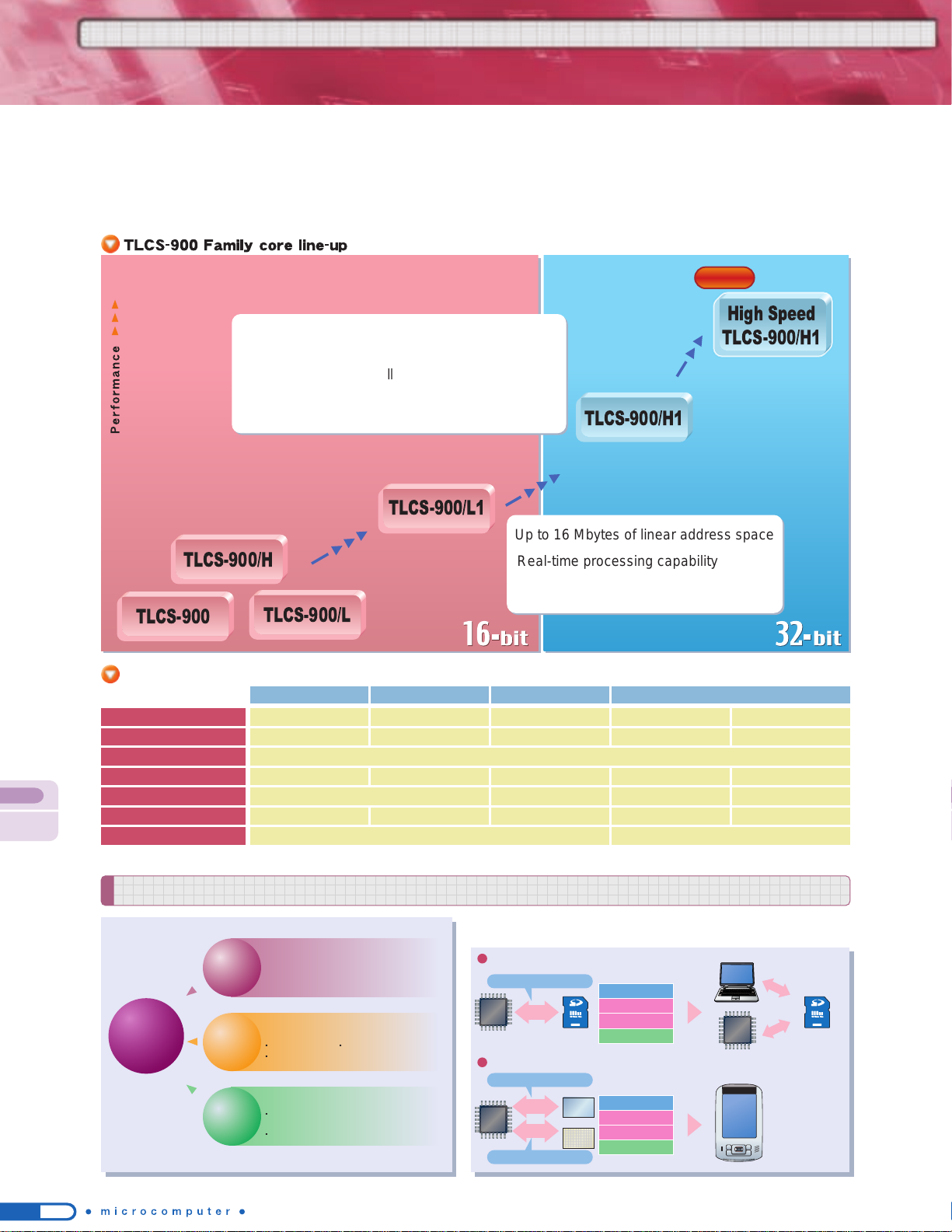
44
Touch panel
LCD
25 to 36 MHz
(12.5 MHz to 18 MHz internal)
Processing capability four times higher than 16-bit 900
devices achieved by 32-bit implementation and faster
internal processing
20 MHz
Suitable for high-performance and multifunctional home appliances, audio equipment and portable devices
The TLCS-900 Family of 16-bit and 32-bit microcontrollers provides solutions in every application field by offering a
wide variety of built-in peripheral functions that can be used in combination with our software IP products. The instruction code compatibility within the 900 Family which ensures a smooth migration from the TLCS-900/L1 16-bit to
TLCS-900/H1 32-bit systems enhances the product line-up strategies.
Software configuration
Files can be
shared between
PC and MCU.
Handwritten
character
recognition
TLCS-900
TLCS-900/H
TLCS-900/L
TLCS-900/L1
TLCS-900/H1
High Speed
TLCS-900/H1
Up to 16 Mbytes of linear address space
Real-time processing capability such as
high-speed instruction execution
by task switching (4 banks)
80 MHz
Processing capability
four times higher than
the standard 900/H1
Toshiba offers total solutions including hardware, systems and software.
TLCS-900
Family
16/32-
bit Microcontrollers
Features of TLCS-900 Family
High-speed operation with
low power consumption
The 900 Family is capable of high-speed operation
while achieving low power consumption.
These features make it ideal for embedded applications.
Application-oriented peripheral functions
Smaller systems Reduced system costs
Shorter development time
Excellent architecture compatibility
Supports development of simple to
advanced devices.
Allows a smooth migration from 16-bit to 32-bit.
Application examples
SD card access
Handwritten character recognition
Application layer
FAT driver
SD driver
MCU hardware - TSI
Software configuration
Application layer
TSI driver
LCD driver
MCU hardware - LCDC
SPI
FAT file system + SD card driver
TSI
LCDC
Character recognition + TSI driver
GUI + LCD driver
Completely compatible instruction codes enable
a smooth migration from 16-bit to 32-bit.
You can use the TLCS-900 Family to develop
general-purpose to advanced devices.
Note 1) Maximum operating frequency varies depending on the product, so please see the "Part Number List" for details.
900/L Series 900/H Series 900/L1 Series 900/H1 Series
10 MHz
200 ns
1.6 µs/2 bytes @20 MHz
12.5 MHz
160 ns
0.64 µs/2 bytes @25 MHz
18 MHz
111 ns
0.44 µs/2 bytes @36 MHz
20 MHz
50 ns
0.25 µs/4 bytes @20 MHz internal
Up to 16 Mbytes of linear address space (for program and data)
5 V/3 V 5 V/3 V/2 V 5 V/3 V
2.6 µs 960 ns
666 ns
8-/16-bit
400 ns
8-/16-/32-bit
80 MHz
12.5 ns
62.5 ns/4 bytes @80 MHz internal
3.3 V, 1.5 V (two power supplies)
134 ns
Maximum internal operating frequency
Note 1)
Minimum instruction execution time
Address space
Data transfer rate (micro DMA)
Operating voltage
Multiplication instruction execution time
(16-bit operands, 32-bit result)
Dynamic bus sizing
MCU
MCU
MCU
Processor core features
High-speed
CPU
performance
Extensive
peripheral
functions
Seamless
family
compatibility
CPU core ideal
for embedded
applications
TLCS-900
NEW

45
TMP92CY23FG/DFG TMP92CD23AFG/DFG
TLCS-900/H1 Series
Under
development
NEW
TMP92CF29FG
High-speed TLCS-900/H1 Series
Single-chip 32-bit microcontrollers with a wide range of built-in I/O functions
The TMP92CY23 and TMP92CD23A are single-chip 32-bit microcontrollers containing a wide range of I/O functions
based on the 900/H1 core.
● Internal ROM: TMP92CY23 256 Kbytes
TMP92CD23A 512 Kbytes
● Internal RAM: TMP92CY23 16 Kbytes
TMP92CD23A 32 Kbytes
● Operating voltage: 3.0 to 3.6 V
● Minimum instruction execution time:
50 ns (internal: 20 MHz)
● SIO/UART: 3 channels*
● SIO/I2C: 2 channels
● 16-bit timer: 2 channels
● 8-bit timer: 6 channels
● 10-bit AD converter: 12 channels
● Key-on-wakeup: 8 channels
● Program patch logic: 8 banks
● Package: TMP92CY23FG/CD23AFG:
100-pin LQFP (14 x 14 mm, 0.5-mm pitch)
TMP92CY23DFG/CD23ADFG:
100-pin QFP (14 x 20 mm, 0.65-mm pitch)
● Flash version:
TMP92CY23FG/DFG: TMP92FY23FG/DFG
TMP92CD23AFG/DFG: TMP92FD23AFG/DFG
(Under development)
*One of the channels in the TMP92CD23A can operate as a high-speed SIO.
This product uses the SuperFlash
O
R
technology under the license of Silicon Storage Technology, Inc.
SuperFlash
O
R
is a registered trademark of Silicon Storage Technology, Inc.
Under
development
Highly functional 32-bit microcontroller with color LCD controller,
capable of operating at 80 MHz
The TMP92CF29 is a 32-bit microcontroller incorporating large-capacity RAM (144 Kbytes) housed in a 176-pin LQFP.
● Internal ROM: 8 Kbytes (Boot)
● Internal RAM: 144 Kbytes
● Operating voltage
Internal : 1.4 to 1.6 V
I/O : 3.0 to 3.6 V
● Minimum instruction execution time:
12.5 ns (internal: 80 MHz)
● USB device: 1 channel
● Memory management unit: 2.1 GB (max)
● SDRAM controller: 512 Mbits (max)
● Color LCD controller: 65K colors (TFT)/
262K colors (STN)
● MLC/SLC NAND Flash interface: 2 channels
● DMA controller: 6 channels
● Multiply-accumulate (MAC):
1 channel (32 x 32 + 64 = 64)
● SD card interface: 1 channel (SPI mode)
● I2S interface: 1 channel
● SIO/UART: 1 channel
● I2C bus: 1 channel
● 8-bit timer/counter: 8 channels
● 16-bit timer/counter: 2 channels
● 10-bit AD converter: 6 channels
● RTC: 1 channel
● Touch screen interface: 1 channel
● Package: 176-pin LQFP
(20 x 20 mm, 0.4-mm pitch)

46
Internal ROM: 512 Kbytes
Internal RAM: 32 Kbytes
Operating voltage: 3.0 to 3.6 V
Minimum instruction execution time: 50 ns
(internal: 20 MHz)
USB host controller
UART/SIO: 2 channels
SBI: 2 channels
HSIO: 1 channel
SPI controller: 1 channel
8-bit timer: 6 channels
16-bit timer: 2 channels
Key-on wake-up: 4 channels
Program patch logic: 8 banks
Package:
TMP92FD28FG/TMP92CD28FG:
1
00-pin LQFP (14 x 14 mm, 0.5-mm pitch)
TMP92FD28DFG/TMP92CD28DFG:
100-pin QFP (14 x 20 mm, 0.65-mm pitch)
TMP92FD28FG/DFG TMP92CD28FG/DFG
TLCS-900/H1 Series
Highly functional 32-bit microcontrollers with a USB host controller
The TMP92FD28 and TMP92CD28 are 32-bit microcontrollers containing a USB host controller based on
the 900/H1 core.
NEW
TMP91FW60FG/DFG TMP91CW60FG/DFG
TLCS-900/L1 Series
16-bit microcontrollers supporting 5-V operation and a wide range of
I/O functions on a single chip
The TMP91FW60 and TMP91CW60 are 16-bit microcontrollers that suppor t 5-V operation and incorporate a wide
variety of I/O functions on a single chip.
Internal ROM: 128 Kbytes
Internal RAM: 8 Kbytes
Operating voltage: 4.5 to 5.5 V
Minimum instruction execution time: 200 ns
(internal: 20 MHz)
SIO/UART: 3 channels
I2C/SIO: 2 channels
8-bit timer/counter: 6 channels
16-bit timer/counter: 5 channels
10-bit AD converter: 16 channels
Program patch logic: 6 banks
Package:
TMP91FW60FG/TMP91CW60FG:
100-pin LQFP (14 x 14 mm, 0.5-mm pitch)
TMP91FW60DFG/TMP91CW60DFG:
100-pin QFP (14 x 20 mm, 0.65-mm pitch)
NEW
This product uses the SuperFlash
O
R
technology under the license of Silicon Storage Technology, Inc.
SuperFlash
O
R
is a registered trademark of Silicon Storage Technology, Inc.
This product uses the SuperFlash
O
R
technology under the license of Silicon Storage Technology, Inc.
SuperFlash
O
R
is a registered trademark of Silicon Storage Technology, Inc.
Under
development
Under
development

47
Features of TLCS-870 Family
2 banks
15 0
15 0
SP
15 0
PC
70
PSW
W
B
D
H
A
C
E
L
IX
IY
TLCS-870/X
Series
TLCS-870/C1
Series
TLCS-870/C
Series
TLCS-870
Series
◆
Core architecture optimized for C compiler
◆
Address space extended to
1Mbyte
◆ High-speed processing capability equivalent to 16-bit microcontrollers
◆ Address space extended to 128 Kbytes
◆ 5-V operation
◆ On-chip debug function
Performance
Software design facilitatedCompact core and object sizes
64-Kbyte code
segment
64-Kbyte code
segment
Code
Data
Code
Additional code
Data
Code:Instruction op-codes and operands
Data: Sources and destinations of load and
arithmetic instructions, etc.
Unlike the bank switching method, small- to largesized programs need not be modified. Processing
speed and code efficiency are unaffected even if
the code size exceeds 64 Kbytes.
Compared to the address bus extension
method, core and code sizes are
reduced. The instruction set is compatible
with TLCS-870/C.
Code and data in the same area
Processor core features
Register configuration
Memory management method
(segment method)
[TLCS-870/C1 Series]
[TLCS-870/C1 Series]
NEW
NEW NEW
Toshiba microcomputer core line-up
NEW
Segment method
Conventional 8-bit product
Segment method
Toshiba's proprietary memory segment method manages instr uction codes and data
independently in separate memory address spaces. This new method enables memory
address space extension without affecting processing speed or code efficiency for
small- to large-sized programs exceeding 64 Kbytes.
TLCS-870
Family
8-
bit Microcontrollers
8-bit microcontrollers suitable for a wide range of consumer products such as home appliances,
communications devices and inverter-controlled equipment
The TLCS-870 Family consists of 8-bit microcontrollers developed for consumer applications such as home appliances, TVs, audio equipment, telephones, motor control and lighting devices. The product line-up includes microcontrollers incorporating various functions to suit these applications,
including an AD converter, LCD driver, UART, on-screen display circuit, IGBT controller and PMD circuit. The 870 Family also offers products featuring low-voltage, low-power-consumption and low-noise operation that are suitable for portable equipment and many other applications. The 870
Family has been reinforced by the TLCS-870/C1 Series which delivers enhanced processing capability and upgraded low-voltage and low-powerconsumption features such as on-chip Flash memory, a voltage detecting circuit and a power-on reset circuit.
16 MHz
0.25 µs/0.167 µs
64 Kbytes
31
731 instructions
1.8 to 5.5 V
8 MHz
0.5 µs
64 Kbytes
15
412 instructions
2.7 to 5.5 V/6.0 V
8 MHz
0.125 µs
128 Kbytes
52
732 instructions
2.7 to 5.5 V
20 MHz
0.2 µs
1 Mbyte
63
842 instructions
2.7 to 5.5 V
Maximum operating frequency
Minimum instruction execution time
Address space
Interrupt vector (max)
Instruction set
Operating voltage range (typ.)
870/C Series 870/X Series 870 Series 870/C1 Series

48
*The minimum instruction execution time is reduced by half compared to TLCS-870/C.
TLCS-870/C1 Series: Minimum instruction execution time of 125 ns
TLCS-870/C Series: Minimum instruction execution time of 250 ns
16KB
32KB
60KB
96KB
ROM
LCD driver built-inStandard product
Flash version or mask version can be selected.
42-pin 44-pin 48-pin 64-pin 80-pin 100-pin
One instruction cycle operated in a single clock cycle
[TLCS-870/C1 Series]
Noise reduction measures
870/C1 Series road map
(planned)
NEW NEW
Separate power supplies Optimized pin layout
Noise filter
Decoupling capacitor
Oscillator protection
Internal VDD
Xin
Internal VSS
I/O VDD
I/O VSS
Internal
logic
OSC
Oscillator pins
Filter
I/O
buffer
Prevents internal
noise from
propagating
to I/O pins.
Prevents noise
propagation.
Enables power supply
decoupling and current
loop minimization.
Separate power supplies are used for internal
logic and I/O.
Internal EMI noise can be prevented from
propagating to I/O pins.
Oscillator pins are guarded by GND pins.
Spurious noise from oscillator pins can be
suppressed.
Spike noise can be eliminated.High-frequency noise can be eliminated by
placing a noise filter.
A decoupling capacitor is attached to the noise source.
High-frequency currents directly flowing to
power supply lines can be reduced.
Spurious noise can be suppressed by minimizing
current loops created by circuit operations.
Xout
C1
VSS VDDXIN XOUT
External pin noise
Noise-free internal signal
(VSS)
TEST
C2
X'TAL
Filter
Pin
Circuit
block
Packages:
UG: 64-pin LQFP (10 mm x 10 mm/0.50-mm pitch)
FG: 64-pin QFP (14 mm x 14 mm/0.80-mm pitch)
TMP89CM60UG/FG
++
TMP89CS60UG/FG
++
TMP89FS60UG/FG
✽✽
32 KB
60 KB
60 KB
3.0 KB
3.0 KB
3.0 KB
✽✽
: Under development
++
: Under planning
The core architecture is configured to reduce the number of clock cycles
required to complete one machine cycle to a single clock cycle. This achieves
processing performance four times that of TLCS-870/C Series at the same
internal clock frequency.
1
1
2 3 4
Internal clock
TLCS-870/C
Series
TLCS-870/C1
Series
One machine cycle
One machine cycle
Part Number ROM RAM
The TLCS-870 Family implements various measures for improving noise immunity.
TLCS-870
Family

49
NEW
TMP86FH09NG/809NG/409NG
TLCS-870/C Series
8-bit microcontroller based on the new 870/C1 core realizing enhanced functionality and performance
The TMP86FS60 is an 8-bit microcontroller based on the new 870/C1 core that achieves processing capability four
times higher than our popular high-performance 870/C Series (at the same internal clock frequency). This new microcontroller contains large-capacity Flash memory, a voltage detecting circuit, a power-on reset circuit, various serial interfaces and timer/counters. In addition to the standard real-time emulator, the TMP86FS60 also supports on-board debugging to enhance development efficiency and product quality.
Internal ROM: 60 Kbytes (Flash)
Internal RAM: 3 Kbytes
I/O ports: 56 pins
Operating voltage: 2.7 to 5.5 V
Minimum instruction execution time:
0.125 µs (8 MHz/4.5 to 5.5 V)
0.24 µs (4.2 MHz/2.7 to 5.5 V)
122 µs (32.768 kHz/2.7 to 5.5 V)
10-bit AD converter: 16 channels
Serial interface
UART/SIO: 2 channels
I
2
C/SIO: 1 channel
UART: 1 channel
*
Up to two SIO channels can be used simultaneously.
Timer/counter
16-bit: 2 channels
8-bit: 4 channels
Voltage detecting circuit
(two voltage levels detectable)
Power-on reset circuit
Key-on wake-up: 8 channels
Package:
TMP89FS60UG:64-pin LQFP
(10 x 10 mm, 0.50-mm pitch)
TMP89FS60FG:64-pin QFP
(14 x 14 mm, 0.80-mm pitch)
8-bit Flash microcontroller in a compact package suitable for home appliances and control equipment
The TMP86FH09, TMP86F809 and TMP86F409 are follow-up products to our popular TMP86C807/808. These new
microcontrollers offer enhanced usability by incorporating a 10-bit AD converter and Flash memory.
Internal ROM: 16 K/8 K/4 Kbytes (Flash)
Internal RAM: 512 Kbytes
I/O ports: 26 pins
Operating voltage: 2.7 to 5.5 V
Minimum instruction execution time:
0.25 µs (16 MHz/4.5 to 5.5 V)
0.50 µs (8 MHz/2.7 to 5.5 V)
122 µs (32.768 kHz/2.7 to 5.5 V)
10-bit AD converter: 6 channels
Serial interface
8-bit SEI: 1 channel
UART: 1 channel
Timer/counter
16-bit: 1 channel
8-bit: 2 channels
Key-on wake-up: 4 channels
Package: 32-pin SDIP
This product uses the SuperFlash
O
R
technology under the
license of Silicon Storage Technology, Inc.
SuperFlash
O
R
is a registered trademark of Silicon Storage
Technology, Inc.
This product uses the SuperFlash
O
R
technology under the
license of Silicon Storage Technology, Inc.
SuperFlash
O
R
is a registered trademark of Silicon Storage
Technology, Inc.
TMP89FS60UG/FG
TLCS-870/C1 Series
Under
development

50
TMP86FH92IDMG
TLCS-870/C Series device with power-on reset and voltage detecting circuits
8-bit microcontroller incorporating a power-on reset circuit and a voltage detecting circuit
The TMP86FH92I is an 8-bit microcontroller that incorporates synchronous and asynchronous serial interfaces, a power-on reset circuit and a voltage detecting circuit. The mask ROM version is also being planned.
Internal ROM: 16 Kbytes
Internal RAM: 512 bytes
Minimum instruction execution time:
0.25 µs (16 MHz/4.0 to 5.5 V)
0.50 µs (8 MHz/3.0 to 5.5 V)
Operating voltage:4.5 to 5.5 V (16 MHz)
3.0 to 5.5 V (8 MHz)
UART: 1 channel
I2C/SIO: 1 channel
SEI: 1 channel
10-bit AD converter: 6 channels
Package: 30-pin SSOP
Power-on reset circuit
Voltage detecting circuit (two voltage levels detectable)
This product uses the SuperFlash
O
R
technology under the
license of Silicon Storage Technology, Inc.
SuperFlash
O
R
is a registered trademark of Silicon Storage
Technology, Inc.
Under
development
TLCS-870
Family

51
T4X
Series
/ T6H
Series
T4X Series
Reduce development time and total cost down
Target system: Battery usage product with LCD
(Calculator, Watch, Health equipment, Remote controller, LCD game and Toys etc.)
High performance CPU: T4X CPU built-in special architecture that means 2 clocks needs to 1 execute instruction.
Low power consumption: T4X's low power consumption make possible long time operation of the equipment run on battery.
Low voltage operation: Memory, LCD driver, I/O and the other peripheral circuits required for hand held equipment are integrated on 1 chip.
Dice form: All T4X family can be supplied in dice form.
4-Bit / 8 -Bit LL Microcontroller
TMP04030 TMP04070
T4X
32 KW
4 K bits
4 K bits
18 ch
64SEG x 16COM
8 bit x 2 ch or
16 bit x 1 ch
1 ch
1 ch
-
-
-
-
2.5 to 3.5 V
Dice
(117 pad)
T4X
16 KW
2 K bits
6 K bits
17 ch
60SEG x 8COM
58SEG x 10COM
8 bit x 2 ch or
16 bit x 1ch
1 ch
-
-
-
-
-
-
1.2 to 1.8 V or
2.4 to 3.6 V
QFP100pin
Dice
TMP04081
T4X
32 KW
2 K bits
16 K bits
17 ch
60SEG x 8COM
60SEG x 10COM
8 bit x 2 ch or
16 bit x 1 ch
1 ch
-
-
-
-
-
-
1.2 to 1.8 V
Dice
(102-pin)
TMP04100
T4X
64 KW
4 K bits
4 K bits
20 ch
60SEG x 16COM
8 bit x 2 ch or
16 bit x 1 ch
-
1 ch
-
-
(ver1.1)
2.5 to 3.5 V
Dice
(121-pin)
T6F36
T4X
24 KW
4 K bits
-
18 ch
50SEG x 15COM
8 bit x 2 ch
1 ch
-
-
1 ch
-
1.8 to 3.5 V
Dice
(132-pin)
T6F42
T4X
52 KW
4 K bits
-
18 ch
50SEG x 15COM
8 bit x 2 ch
1 ch
-
-
1 ch
-
1.8 to 3.5 V
Dice
(132-pin)
CPU
ROM
Work RAM
Data RAM
I/O port
LCD driver
(Built-in regulator)
Timer/Counter
Buzzer circuit
Melody circuit
SIO
UART
USB
External SRAM I/F
External LCDD I/F
Operating voltage
Package
Wireless remote
controllers
IC card R/W
Digital clocks
Data banks
Wired remote controllers
Single-lens Reflex Camera
Lens Shutter Camera
Handheld LCD games
Calculators
Health equipment
Low-current-consumption
microcontrollers
4-Bit
8-Bit
16-Bit
T4X Series Line-up
Application for personal usage

52
T4X
Series
/ T6H
Series
4-Bit / 8 -Bit LL Microcontroller
T6H82C T6H87
TLCS-870/C
32 KB
1 KB
64
40SEG x 4COM
Input 8 ch (Internal 1 ch)
Output 2 ch (Internal 2 ch)
1 ch
4 ch
1 ch
1 ch
12 ch
1.5 ch (P-ch/N-ch open drain x 3 ch)
1.8 to 5.5 V
TQFP100pin Dice
EEPROM (T6H83C)
TLCS-870/C
24 KB
1 KB
44
24SEG x 4COM
Input 8 ch (Internal 1 ch)
Output 2 ch (Internal 2 ch)
1 ch
4 ch
1 ch
1 ch
8 ch
1.5 ch (P-ch/N-ch open drain x 3 ch)
1.8 to 5.5 V
LQFP80pin Dice
EEPROM (T6H88)
CPU
ROM
RAM
I/O port
LCD driver
(Built-in regulator/Charge-pump)
8-bit ADC
8-bit DAC
16-bit timer/counter
8-bit timer/counter
SIO
UART
External interrupt
Motor pre-driver
Operating voltage
Package
None volatile (NV) type
T6H Series Line-up
Reduce development time and total cost down
Target system: Battery usage product with LCD
(Compact camera, Health equipment, Home appliance, Remote controller, Toys etc.)
Low voltage & Low power consumption for battery use application
Operation voltage: 1.8 to 5.5V
Low power consumption: IQD < 15 µA(@V
DD
= 5.0 V, LCD display ON)
Low power oscillator: Low speed clock 32.768 kHz
Low power regulator (Regulator for LCD driver, regulator for oscillator)
Built-in logic circuits to reduce software development time
Blinking operation for LCD, External interrupt ports for SW with sampling detection
Built-in analog circuits for actuator control
8-bit AD Converter, 8-bit DA Converter
Comparator with variable detected level
Motor drive control with pre-drives
T6H Series

53
Development System
Toshiba Semiconductor Website
http://www.semicon.toshiba.co.jp/eng/index.html
Information on the entire spectrum of
Toshiba semiconductor products is
avaiable here.
Toshiba Microcomputer Website
http://www.semicon.toshiba.co.jp/eng/prd/micro/index.html
A line-up of Toshiba microcomputer products
and the latest technical information on
products are presented here.
Click
Toshiba Microcomputer
Development System Product Website
Click
This website provides the latest information on Toshiba
microcomputer development system products.
To suit the different aims of visitors, the website includes
the pages for examinating customers and current users.
Page for Examinating Customers
●
A system developed for each Family and Series of products is
available.
●
A list of third-party tools supported
for each vendor can be viewed.
Page for Users
User Registration
Once you have completed user registration on our New User
Registration page, you will be issued with a user ID and password
for accessing the user page.
●
You can see new product information and receive updates to
the products you currently use.
●
You can access technical information and helpful information
on product usage.
●
You can download the following latest data and resources:
●
Software product ● Instruction manual PDF files
●
Operation manual PDF files ● Firmware

54 55
TX19 series TX19A series
The C Compiler package containing C Compiler, Assembler and Linker allows you to generate
object files such as HEX files from source code written in C or assembly language. It conforms to
the ANSI C standard and offers excellent descriptiveness and portability. A wide range of options are
provided to improve code efficiency and RAM utilization. This product is used in combination with the
TX19 Family Integrated Development Environment. TX19 Series version and TX19A Series version
are available.
The basic development system environment for the TX19 Family is summarized below. The specified values are the recommended values for comfortable
use. For the minimum operating environment, check with the product manual of each development system product.
Software used to control multitasking in embedded systems.
Conforms to µITRON specifications.
Ample system calls required for embedded systems.
Use of the configuration tool facilitates data setting of timer, task, etc.
Offered in two versions: object version and object & source version. The object &
source version allows users to modify the source programs.
Development system configuration examples
Basic performance
Toshiba Integrated Development Environment (TIDE)
Real-Time OS
DSU PROBE is an on-board emulator that enables efficient
debugging. It provides emulation and debugging features that
are useful for developing application programs by being
connected to the target system and operated from the
debugger on a PC.
Emulator
TLCS-900 Family C Compiler
Outline of TX19 Family Development System
User source
program
Target
system
Software products
Object file
TX19 Series Integrated Development Environment
TX19A Series Integrated Development Environment
TX19 Series C Compiler
TX19A Series C Compiler
Toshiba Integrated Development Environment (TIDE)
Hardware products
Software products
TX19 Series Real-Time OS
TX19A Series Real-Time OS
Real-Time OS
Emulator
C Compiler
Assembler
Build Manager
Simulator
Debugger
Linker
Framework
Editor
With individual development tools such as Editor, Build Manager, Compiler and Debugger integrated
into one, the Integrated Development Environment enables seamless operations of coding, building
and debugging tasks which must be performed repeatedly in the software development process. It
also contains a simulator function for simulating MCU operations for logical debugging, and a debug
function supporting real-time OS. TX19 Series version and TX19A Series version are available.
TX19 Family Integrated Development Environment
C Compiler
Assembler
Build Manager
Simulator
Debugger
Linker
Framework
Editor
* The term “Toshiba Integrated Development Environment (TIDE)”
refers collectively to the TX19 Family Integrated
Development
Environment and the TX19 Family C Compiler.
TX19 Series emulator
DSU PROBE for N-WIRE
Includes a debugger specifically tailored to the TMP1940/42.
For development work using other MCUs, you need to
purchase the TX19 Series Integrated Development
Environment.
TX19A Series emulator
DSU PROBE model 110/120
model 120 is a higher-end product to model 110.
Includes the TX19A Series Integrated Development
Environment without simulator function
(downloadable from our website).
HUB
Target board
DSU PROBE
Target board
RS-232C Cable
DSU PROBE
DSU PROBE for N-Wire system
LAN card
Host machine
OS: Windows 2000/XP Host machine: IBM-PC/AT compatible
Host machine CPU: Pentium 4 1 GHz or faster (recommended)
Memory: 512 MB or larger (recommended)
Display resolution: 1280 x 1024 or higher
Extended I/O port: 1 port (RS-232C) (TX19A only)
Expansion slots: 1 port (for LAN card)
Hub
Ethernet hub
Support for 10BASE-T
Conformance to
IEEE 802.3
Ethernet standard
LAN expansion card for PC
Ethernet network interface card
Support for 10BASE-T
Conformance to IEEE 802.3
Ethernet standard
LAN cable
Twisted-pair cable
Products required for minimal system
Toshiba Integrated Development Environment (TIDE)
TX19 Series Integrated Development Environment
..........1
TX19 Series C Compiler....................................1
Emulator
DSU PROBE for N-WIRE ..................................1
Other required products
Windows PC ......................................................1
LAN expansion card for PC ...............................1
Hub ....................................................................1
RS-232C cross cable.........................................1
LAN cable .........................................................2
Target connectors
20-pin half-pitch plug 104068-1 from AMP ........1
20-pin half-pitch plug FTSH-110-01-F-D-K from SAMTEC
.....1
DSU PROBE model 110 system
Products required for minimal system
Toshiba Integrated Development Environment (TIDE)
TX19A Series Integrated Development Environment
........1
TX19A Series C Compiler .................................1
Emulator
DSU PROBE model 110 ...................................1
Other required products
Windows PC......................................................1
LAN expansion card for PC...............................1
Hub....................................................................1
RS-232C cross cable.........................................1
LAN cable .........................................................2
Target connectors
20-pin half-pitch plug FTSH-110-01-F-D-K from SAMTEC
.....1
34-pin half-pitch plug FTSH-117-01-F-D-K from SAMTEC
.....1
DSU PROBE model 120 system
Products required for minimal system
Toshiba Integrated Development Environment (TIDE)
TX19A Series Integrated Development Environment
........1
TX19A Series C Compiler .................................1
Emulator
DSU PROBE model 120 ...................................1
Other required products
Windows PC......................................................1
LAN expansion card for PC...............................1
Hub....................................................................1
RS-232C cross cable.........................................1
LAN cable .........................................................2
Target connectors
20-pin half-pitch plug FTSH-110-01-F-D-K from SAMTEC
.....2
34-pin half-pitch plug FTSH-117-01-F-D-K from SAMTEC
.....1
* For part numbers, see "PART NUMBER LIST" or our Development System website.
System name
TX19 Series
DSU PROBE for N-Wire system
Host interface
Trace memory
Events
Program variables
Break
Memory access
Capacity
Trace modes
Trace items
External output
Number of points
Comparison items
Comparison conditions
Pass count
Event trigger actions
Event combinations
Display
Registration
Source display
External input
Flash programming/security feature
Software break
Hardware break
Timer measurement
Memory display during program execution
Memory rewrite during program execution
TX19A Series
DSU PROBE model 110 system DSU PROBE model 120 system
Ethernet, RS-232C Ethernet, RS-232C
Instruction: 8 points, Data: 4 point
Address, data, status, external input
4 lines
Variables: 16-byte area x 32, Memory: Up to 1024 bytes
4 bytes x 4 blocks can be written simultaneously.
Variables, arrays, structures and unions can be registered by the elements.
Binary, octal, decimal or hexadecimal display can be selected for each variable.
Match
Once 1 to 256 times
8 points
256 points (settable only on RAM)
4K frames 128K frames
Free trace, trigger trace, overflow stop
PC address, status, tag timer
PC address, data address,
data value, status, tag timer
Run timer: 1 channel Lap timer: 1 channel
Run timer: 1 channel
Lap timer: 4 channels
(max., min., average, count)
OR, sequential
Instruction: 4 points, Data: 1 point
(Note 1)
Address, data, status, external input
Match
Once
Break, trace control, timer control, external trigger output
Break, trace control, timer control, external trigger output,
external pulse output, memory write
-
4 points
(Note 1)
256 points (settable only on RAM)
4K frames
Free trace, trigger trace, overflow stop
PC address, status, tag timer
-
Run timer: 1 channel Lap timer: 1 channel
-
-
Source
Source + assembler code
Source + assembler code + machine language
Source
Source + assembler code
Source + assembler code + machine language
Internal/external Flash memory can be programmed during debugging.
(Note 2)
1 line
Internal/external Flash memory can be programmed during debugging.
1 line
Binary, octal, decimal or hexadecimal display can be selected for each variable.
Variables, arrays, structures and unions can be registered by the elements.
µITRON
specifications
Source programs
Configuration
tool
TX19 Series
Object version
Object &
source version
µITRON 3.0 specifications
TR Configurator
Not included Included
TX19A Series
Object version
Object &
source version
µITRON 4.0 specifications
TRcEditor
Note 1: Varies with the MCU to be used. Note 2: Some MCUs do not support this feature.
DSU PROBE
Target board
RS-232C Cable
DSU PROBE
Not included Included
Connection exapmle
An appropriate connector with DSU PROBE
must be soldered on the target board.

56 57
Toshiba Integrated Development Environment (TIDE)
The basic development system environment for the TLCS-900 Family is summarized below. The specified values are the recommended values for
comfortable use. For the minimum operating environment, check with the product manual of each development system product.
Development system configuration examples
Basic performance
RTE900 model 15 system
The model 15 system is a low-cost version of the model 25 system that is
realized by offering the minimum functionality required for development work
and an extensive use of gate arrays.
RTE900 model 25 system
The model 25 system features enhanced hardware that enables faster
processing to support high-speed and high-functionality MCUs and provide
advanced debug capability such as performance analysis.
* A combination of the model 25 controller and the model 15 emulation pod is also
possible.
Emulator
Outline of TLCS-900 Family Development System
Programming tools
Accessories
TLCS-900 Family Real-Time OS
µITRON 3.0 specifications
Object code
Source programs
TR Configurator
TR Editor
Source programs
TR Configurator
TR Editor
Object version
Object code
Object & source version
HUB
Target board
Controller
Pod
RTE900 model 15 system
LAN card
Host machine
OS: Windows 2000/XP Host machine: IBM-PC/AT compatible Host machine CPU: Pentium 4 1 GHz or faster (recommended)
Memory: 512 MB or larger (recommended) Display resolution: 1280 x 1024 or higher Expansion slots: 1 port (for LAN card)
Hub
Ethernet hub
Support for 10BASE-T
Conformance to IEEE 802.3
Ethernet standard
LAN expansion card for PC
Ethernet network interface card
Support for 10BASE-T
Conformance to IEEE 802.3 Ethernet standard
LAN cable
Twisted-pair cable
Products required for minimal system
Toshiba Integrated Development Environment (TIDE)
TLCS-900 Family Integrated Development Environment ...............................1
TLCS-900 Family C Compiler.........................................................................1
Emulator
model 15 controller.........................................................................................1
model 15 emulation pod .................................................................................1
Accessories Programming tools
MCU probe Pin protector OTP programming adapter
QFP adapter MCU mounting adapter Flash adapter
Other required products
Windows PC...................................................................................................1
LAN expansion card for PC............................................................................1
Hub.................................................................................................................1
RS-232C cross cable......................................................................................1
LAN cable ......................................................................................................2
Target board
Controller
Pod
RTE900 model 25 system
Products required for minimal system
Toshiba Integrated Development Environment (TIDE)
TLCS-900 Family Integrated Development Environment ...............................1
TLCS-900 Family C Compiler.........................................................................1
Emulator
model 25 controller.........................................................................................1
model 25 emulation pod .............................................................1
Accessories Programming tools
MCU probe Pin protector OTP programming adapter
QFP adapter MCU mounting adapter Flash adapter
Other required products
Windows PC...................................................................................................1
LAN expansion card for PC............................................................................1
Hub.................................................................................................................1
RS-232C cross cable......................................................................................1
LAN cable ......................................................................................................2
* For part numbers, see "PART NUMBER LIST" or our Development System website.
--
RTE900 model 25 system RTE900 model 15 system
Note 1: When you are using a device whose part number starts with TMP92.
Software products
Object file
Hardware products
Software products
Emulator
User source
program
Target
system
Real-Time OS
Controller
Emulation pod
System name
Host interface
Trace memory
Events
Program
variables
Break
Memory
access
Capacity
Trace modes
Trace items
External output
External input
Number of points
Comparison items
Comparison conditions
Pass count
Event trigger actions
Event combinations
Display
Registration
Performance
analysis
Time measurement per module
Coverage measurement
Source display
Software break
Hardware break
Timer measurement
Memory display
during program execution
Emulation memory
Capacity
TLCS-900, 900/H, 900/L, 900/L1 Series
model 15 system model 25 system
Ethernet, RS-232C
8 points
1 line
32 bytes
Variables, arrays, structures and unions can be registered by the elements.
Binary, octal, decimal or hexadecimal display can be selected for each variable.
Match, unmatch, within scope
1 to 65535 times
3 points
1024 points
8K frames
Free trace, trigger trace, sampling trace, overflow stop
PC address, data address,
data value, status
PC address, data address, data value, status,
external input, tag timer, event
Run timer: 1 channel, Lap timer: 1 channel
AND, OR, sequential
Break, trace control, timer control, external trigger output
Source
Source + assembler code
Source + assembler code + machine language
TLCS-900/H1 Series
(Note 1)
model 15 system model 25 system
Ethernet, RS-232C
4 Mbytes
8 points
Address, data, status, external input
1 line
128 bytes
Variables, arrays, structures and unions can be registered by the elements.
Binary, octal, decimal or hexadecimal display can be selected for each variable.
Match, unmatch, within scope
1 to 256 times
4 points
1024 points
8K frames
Max., min, average, count, dispersion
4 Mbytes1 Mbytes
16 line-
Address, data, status, external inputAddress, data, status
Max., min, average, count, dispersion
C0 coverageC0 coverage
Free trace, trigger trace, sampling trace, overflow stop
PC address, data address, data value, status,
external output, external input, tag timer, event
Run timer: 1 channel, Lap timer: 1 channel
AND, OR, sequential
Break, trace control, timer control, external trigger output
Source
Source + assembler code
Source + assembler code + machine language
1 line
TLCS-900 Family Integrated Development Environment
TLCS-900 Family C Compiler
TLCS-900 Family
Real-Time OS
Toshiba Integrated Development Environment (TIDE)
* The term “Toshiba Integrated Development Environment (TIDE)”
refers collectively to the TLCS-900 Family Integrated
Development Environment and the TLCS-900 Family C Compiler.
The C Compiler package containing C Compiler, Assembler and Linker allows you to
generate object files such as HEX files from source code written in C or assembly
language. It conforms to the ANSI C standard and offers excellent descriptiveness and
portability. A wide range of options are provided to improve code efficiency and RAM
utilization. This product is used in combination with the TLCS-900 Family Integrated
Development Environment.
TLCS-900 Family C Compiler
C Compiler
Assembler
Build Manager
Simulator
Debugger
Linker
Framework
Editor
With individual development tools such as Editor, Build Manager, Compiler and Debugger
integrated into one, the Integrated Development Environment enables seamless
operations of coding, building and debugging tasks which must be performed repeatedly
in the software development process. It also contains a simulator function for simulating
MCU operations for logical debugging, and a debug function supporting real-time OS.
TLCS-900 Family Integrated Development Environment
C Compiler
Assembler
Build Manager
Simulator
Debugger
Linker
Framework
Editor
Software used to control multitasking in embedded systems.
Conforms to µITRON specifications.
Ample system calls required for embedded systems.
Use of the TR Configurator facilitates data setting of timer, task, etc.
The TR Editor can be used to describe task operations graphically and to generate program
outlines.
Offered in two versions: object version and object & source version. The object & source version
allows users to modify the source programs.
Real-Time OS

58 59
These software tools containing C Compiler, Assembler and Linker allow you to
generate object files such as HEX files from source code written in C, C-Like(*) or
assembly language.
(*) Supported only with the TLCS-870 Series.
Build Manager with user-friendly GUI is included.
C Compiler conforming to the ANSI C standard offers excellent descriptiveness
and portability.
The basic MCU-dependent development system environment for the TLCS-870 Family is summarized below. The specified values are the recommended
values for comfortable use. For the minimum operating environment, check with to the product manual of each development system product.
Development system configuration examples
Basic performance
Language T ools
Outline of TLCS-870 Family Development System
TLCS-870/C Series C Compiler
TLCS-870/X Series C Compiler
TLCS-870 Series C/C-Like Compiler
Language tools
TLCS-870/C Series Debugger
TLCS-870/C Series Light Debugger
TLCS-870/X Series Debugger
TLCS-870 Series Debugger
Debuggers
C Compiler /
C-Like Compiler
Assembler
Build Manager
Linker
The emulator system for a TLCS-870 Family MCU can be configured by an appropriate combination of a debugger and an emulation pod.
A wide variety of debug functions are available including various types of break settings and real-time trace.
Debugger
HUB
LAN card
Host machine
Host machine: IBM-PC/AT compatible
Host machine CPU: Pentium 4 133 MHz or faster
Memory: 128 MB
Display resolution: 1024 x 768 or higher
Expansion slots: 1 port (for LAN card)
Hub
Ethernet hub
Support for 10BASE-T
Conformance to IEEE 802.3
Ethernet standard
LAN expansion card for PC
Ethernet network interface card
Support for 10BASE-T
Conformance to IEEE 802.3
Ethernet standard
LAN cable
Twisted-pair
cable
Other required products
Windows PC......................1
LAN expansion card
for PC ................................1
Hub....................................1
LAN cable..........................2
* For part numbers, see "PART NUMBER LIST" or our Development System website.
System name
model 10 system
TLCS-870/C SeriesTLCS-870 Series
Light system model 15 system
TLCS-870/X Series
model 15 system
model 25 system
model 15 pod
model 25 pod
(Note 1)
Host interface
Emulation memory
Capacity
Number of points
Events
Trace memory
Performance
analysis
Memory
access
Break
Trace items
Trace modes
Comparison items
Comparison conditions
Pass count
Hardware break
Software break
Capacity
Event trigger actions
Event combinations
External input
External output
Coverage measurement
Time measurement per module
Program
variables
Registration
Display
RS-232C
64 Kbytes
4 points
OR, sequential
points
-
1 line
8 lines
4K frames
PC address, data address,
data value, status, external input
PC address, data address, data value,
status, external input, tag timer
Overflow stop
1 to 65535 times
Break, trace control,
timer control,
external trigger output
Break, trace control,
timer control,
external trigger output
Break, trace control,
timer control,
external trigger output
Address, data, status,
external input
Address, data, status,
external input
Match, unmatch, within scope
USB2.0 Full-speed
64 Kbytes
4 points
OR, sequential
2000 points
2000 points
-
-
-
-
1K frames
PC address, data address, data value, status
Overflow stop
1 to 65535 times
Break
Address, data, status
Match, unmatch, within scope
Ethernet, RS-232C
AND, OR, sequential
1 line
8K frames
Free trace, trigger trace,
sampling trace, overflow stop
Free trace, trigger trace,
sampling trace, overflow stop
Ethernet, RS-232C
1 Mbyte
8 points
AND, OR, sequential
2000 points
2000 points
1 line
Timer measurement
Run timer or Lap timer: 1 channel
Run timer: 1 channel
Run timer: 1 channel Lap timer: 1 channel
Run timer: 1 channel Lap timer: 1 channel
Memory display during program execution
- - 32 bytes 32 bytes
-
-
-
8K frames
PC address, data address,
data value, status
1 to 65535 times
Address, data, status
Match, unmatch, within scope
3 points
2 bytes
(Note 2)
-
16 lines
Max., min., average, count, dispersion
C0 coverage
Memory rewrite during program execution
-
-
-
2 bytes
Binary, octal, decimal or hexadecimal
display can be selected for each variable.
Binary, octal, decimal or hexadecimal
display can be selected for each variable.
Binary, octal, decimal or hexadecimal
display can be selected for each variable.
Variables, arrays, structures and unions can be registred by the elements.
Variables, arrays, structures and
unions can be registred by the elements.
Variables, arrays, structures and unions can be registred by the elements.
Note 1: model 25 pod: BM88CM49N0A, BM88CU74F0A, BM88CP77F0A, BM88C060F0A
Note 2: This function is not supported with the BM88CM49N0B-M15.
As the RTE870/C Light system is designed to share products within
the system, the probe, target connector and emulation chip need to be
changed to accommodate different MCUs in the TLCS-870/C Series.
* Detailed information on the RTE870/C Light system can be found on page 8.
The RTE870/C Light system is a low-cost version of the RTE870/C model
15 system with the minimum functionality required for development work.
TLCS-870/C Series
TLCS-870/X Series
RTE870/C Light system
As the RTE870/C model 15 system is designed to share products within the
system, only the target connecting board and emulation chip need to be
changed to accommodate different MCUs in the TLCS-870/C Series. In this
way, the cost associated with a change of MCU is lowered.
(Some MCUs also require a change of the emulation module.)
RTE870/C model 15 system
Target board
Light emulator
USB
Other required products
Windows PC......................1
LAN expansion card for PC
....1
Hub....................................1
LAN cable..........................2
The RTE870/X model 25 system offers advanced debug capability
such as performance analysis.
RTE870/X model 25 system
The RTE870/X model 15 system is a low-cost version of the RTE870/X model
25 system with the minimum functionality required for development work.
RTE870/X model 15 system
Products required for minimal system
TLCS-870/C Series
C Compiler ....................................1
TLCS-870/C Series
Debugger .......................................1
Accessories
QFP adapter
Pin protector
MCU mounting adapter
Emulator
model 15 controller..............1
Interface module..................1
Emulation module ...............1
Target connecting board ......1
Emulation chip.....................1
Target board
Pod
Controller
RS-232C cable
TLCS-870 Series
RTE870 model 10 system
Target board
Pod
Target board
Pod system
Controller
Emulation module
Interface module
Software products
Object file
Hardware products
Emulator
Source display
Source
Source + assembler code
Source + assembler code + machine language
Source
Source + assembler code
Source + assembler code + machine language
Source
Source + assembler code
Source + assembler code + machine language
Controller
Programming tools
OTP programming adapter
Flash adapter
Products required for minimal system
TLCS-870/X Series
C Compiler ...................1
TLCS-870/X Series
Debugger......................1
Accessories
MCU probe
QFP adapter
Pin protector
MCU mounting adapter
Emulator
model 15 controller ............1
model 15 emulation pod ......1
Programming tools
OTP programming
adapter
Flash adapter
Products required for minimal system
TLCS-870 Series
C/C-Like Compiler .......1
TLCS-870 Series
Debugger......................1
Accessories
MCU probe
QFP adapter
Pin protector
MCU mounting adapter
Emulator
model 10 controller ............1
model 10 emulation pod ......1
Programming tools
OTP programming
adapter
Other required products
Windows PC......................1
RS-232C cross cable
............1
User source
program
Target
system
Controller
Emulation pod
Emulator
Programming tools
Accessories
Products required for minimal system
TLCS-870/C Series C Compiler...........1
TLCS-870/C Series Light Debugger ....1
Accessories
Light-system
probe (probe set).......................1
Programming tools
OTP programming adapter
Flash adapter
Emulator
Light emulator ..................1
Emulation chip .................1
Other required products
Windows PC......................1
USB cable
(USB standard A to B).......1

60
Programming tools / Accessories
Flash adapter
Enables Toshiba's Flash microcontrollers to be programmed on a
stand-alone basis.
Can be used with Toshiba's Flash microcontrollers of any Family
or Series in the same package.
(*The user is required to connect write signals and mount
oscillators as appropriate to each device.)
Comes with "Flash Programmer"-programming control software
controllable on a PC.
Ensures ease of operation through the GUI-based control
software.
Allows programmed data to be compared on a byte basis.
Yokogawa Digital Computer's programmer (NET IMPRESS) can
be used as a host system.
The Flash adapter is provided for each package type of Toshiba’s microcontrollers with on-chip Flash memory.
Connecting the Flash adapter with a host system allows you to program, erase, and verify on-chip Flash memory.
Although this tool can be used both for product development and mass production, some limitations apply when it is
used for mass production. For details, visit Toshiba’s Microcomputer website. The website provides various support
information for the Flash adapter including its control software upgrades to flexibly support newly developed devices.
OTP programming adapter
This is an adapter for converting the pinout of an OTP
microcontroller to that of a general-purpose EPROM. The OTP
programming adapter enables an OTP microcontroller to be
programmed and verified by an off-the-shelf EPROM
programmer. This adapter is provided for each OTP
microcontroller type.
Socket for
mounting
MCU with
on-chip
Flash memory
NET IMPRESS
connector
RS-232C
D-SUB
9-pin male
Power
supply
OTP microcontroller
OTP programming
adapter
EPROM
programming socket
Programming tools
MCU probe
The MCU probe is used to connect a target system and an emulation pod,
and is provided for each package type. The MCU probe used for a flat
package comes with a QFP adapter and a pin protector.
* The RTE870/C Light system requires a probe specifically tailored to the Light
system. For details, see page 8.
Pin protector
The pin protector is a protective socket for an MCU probe and a QFP adapter. Be
sure to use the pin protector to prevent MCU probe's joint from losing its spring
after repeated attachments and detachments.
* We recommend replacing the pin protector after 100 attach-detach cycles.
QFP adapter
The QFP adapter is used to connect an emulation pod or an emulation
module to a target system designed for a QFP-type microcontroller. It is
soldered onto the foot pattern on the target system board.
* Once soldered, the QFP adapter cannot be reused.
* The pin protector and QFP adapter of the same specifications are also available
from Tokyo Eletech Corporation.
MCU mounting adapter
The MCU mounting adapter is used together with the QFP adapter to mount a
microcontroller on the target system.
Accessories
For part numbers and tool combinations,
see "PART NUMBER LIST" or Development System website.
MCU probe
Pin protector
QFP adapter
MCU mounting adapter
QFP adapter

61
Software Development Support
Software IP MCU/Series Features Status
TCP/IP protocol stack
HTTP server
TLCS-900/L1, H1
TLCS-900/L1, H1
JPEG TLCS-900/L1, H1
IrDA protocol stack TLCS-900/L1, H1
USB1.1 (device)
TMP92CH21FG
TMP92CZ26A
TMP92CF26A
TMP92CF29
Available
Available
Available
Available
Available
Ideal for network appliances and network audio products etc. Conforms to RFC and supports
TCP, UDP, IP, ICMP, and ARP.
Supports HTTP 1.0/1.1. Application product control, data gathering, and monitoring from an
external PC or other device are readily achievable.
Exchange of various data is readily achievable by connecting to PC. Supports standard request,
various types of class request, and vender commands.
Software decoder that conforms to ISO/IEC10918-1. The maximum size of an image is QVGA.
Communication with other infrared application devices is feasible. Supports IrPHY, IrLAP, IrLMP,
IrTTP, and IrOBEX.
Embedded file system TLCS-900/L1, H1
File system for embedding. Supports FAT12/16/32 and VFAT, and can perform file sharing with PC.
Speech codec
TLCS-870/C
TLCS-900/L1, H1
Toshiba original compression algorithm. The CPU load and memory usage are optimized to
enable also the control of peripheral devices with embedded state in single-chip microcontroller.
Speech codec application development environment and evaluation board are available.
Available
CompactFlash Driver TLCS-900/L1, H1
Driver Software for reading from and writing to CompactFlash card. Can transfer files to and from
a PC, being incorporated in an embedded file system.
Available
SD Memory Card Driver TLCS-900/L1, H1
TLCS-900/L1, H1
Driver Software for reading and writing SD card with MCU. Can transfer files to and from a PC,
being incorporated in an embedded file system.
Available
Graphics Library TLCS-900/L1, H1
Software that draws figure/text and processes them. It has become also capable of expressing
many colors in fewer colors with its dithering function.
Available
Animation Library TLCS-900/L1, H1
Combining multiple still images, can play them dynamically. Encoded on PC, and decoded on
embedded device.
Available
Available
Handwritten Recognition
Software that recognizes handwritten characters on a LCD panel with a touchscreen. An
embedded device incorporating this software can realize a user-friendly input interface without any
exclusive input device such as key board.
Available
TLCS-900/L1, H1
Graphical Interface
Software for embedded devices with LCD panel. Has functions of various controls, preset interface
and display for PDA. Setting several data makes it possible to display menus and control them.
Available
TLCS-870/C
Authentication Library
8-bit microcontroller-mountable small size program. Software for authentication of high safety.
Authentic method based on ISO/IEC9798-2. Key length is selective from 96 to 256 bits and shall
be activated by function call.
Available
TMP92CZ26A
TMP92CF26A
TMP92CF29
Text To Speech (TTS)
Text To Speech is a means of conversion from text data to speech data. Compared to Speech
Codec, it dramatically saves a storage area when reading various input text data. Moreover, the
speech data is changeable only by replacing it by new one.
Available
Toshiba software IP line-up
Reference application software (RAS)
FTS-171 FTS-172
(Under development)
FTS-151
TMP88CS34FG
TMP88CS38BFG
TMP88CS34FG
TMP88CS34FG
TMP88CS38BFG
-
TMP86FS49AUG
(HDMI Receiver LSI:TC90704MFG)
-
TC90200FG TC90200FG
200200 US181CH
Multi-system color LCD TVs
Multi-system color LCD TVs
supporting HDMI
with CEC function
FS channel tuning for
NTSC color LCD-TV with support
for North American CCD and V-Chip
CTS-777
TMP88CP34NG/FG
-
TB1261ANG
100/200
VS channel tuning for
multi-system color TVs
CTS-851
TMP88CS38NG/FG
-
TB1263NG
US181CH
FS channel tuning for NTSC color TVs with
support for North American CCD and V-Chip
System name
Application
MCU
Sub MCU
Chip IC for color TVs
Channels in memory
NICAM/IGRNICAM/IGR Sound multiplexing for US NICAM/IGR Sound multiplexing for US
Sound multiplexing
TC90200FG
VGA VGA/WXGA CRT CRT
Display
VGA/WXGA
Toshiba provides a variety of reference software for supporting system development.
At customer request, we can also develop application software for embedding in microcontroller units (MCUs).
We have a comprehensive software IP set for customers using (or considering using) Toshiba MCU products.
The software IP and its user support are offered on certain terms and conditions.
In addition, you are required to make an agreement separately in order to use this software IP.
Some of the above software IPs require a separate real-time OS (Toshiba's TR900).
A separate contract is necessary to use RAS. Please consult with us about modifying software to suit customer systems and specifications.
RAS is software for driving an entire system, whose specifications have been created by Toshiba. RAS is developed for reference with the aim of reducing customer software development time, so it is used and evaluated by
customers themselves.
Display the following URL for the overviews of these software IPs.
http://www.semicon.toshiba.co.jp/eng/prd/micro/swip/index.html

62
http://www.semicon.toshiba.co.jp/eng/index.html
We offer a comfortable solution of handwritten character input achieved by the interaction between the handwritten
character recognition and Kana-Kanji conversion.
In addition to the input continued at an uninterrupted pace that was succeeded by Toshiba’s original technology of
overwritten character recognition, the cooperation with an advanced Kana-Kanji prediction and conversion technology
has achieved costless input, which made the input of long sentences stressless. This software is the best thing for
wide range of applications that use LCD and touch panel such as PDA (Personal Digital Assistant), electric dictionary,
home electric appliances.
As for MCU to use, our TLCS-900/H1 series is recommended.
An application note is a sample
software product offered by Toshiba to
help customers understand Toshiba
microcontrollers and learn how to
create programs when developing new
products. To access a download page,
go to "Application Notes" from the
above URL through "Microcomputer." If
you accept and agree to the terms and
conditions for usage, you will see an
application notes list displayed. The
application notes for Toshiba 870/X and
900/H Series are released first, and
those for other MCUs will also be
released sequentially.
TLCS-870/X
Creating TOD Clock Using TBT Interrupts Generating Interrupts at Regular
Intervals Using 8-bit Timer
Generating Interrupts at Regular Intervals
Using Cascaded 8-bit
Outputting 50%-Duty Pulses Using 8-bit Timer
Outputting PWM Waveform Using 8-bit Timer
Outputting PPG Waveform Using 8-bit Timer
Outputting Single-Shot Pulse Using
External Trigger Pulse
Counting Events Using 16-bit Timer
Measuring Frequency Using 16-bit Timer
Detecting Keys Using a Timer
Detecting Keys Using an A/D Converter
RS-232C Communication Using UART
Generating Tone Using PDO
Inter-CPU Communication
(Transmission + Reception) Using SIO
Inter-CPU Communication
(Simultaneous Transmission/Reception) Using SIO
Measuring AC Frequency Using Pulse Width
Measurement Mode
TLCS-900/H
Introducing the Latest Software IP
Application Notes
Handwritten Character Input Solution
Start of Web download services
Handwritten Character Input Package
Overwritten Character
Recognition
Touch Panel Driver
Advanced Wnn is the product of OMRON SOFTWARE Co., Ltd.
is the trademark of TOSHIBA CORPORATION.
LCD Driver
Handwritten Character Kana-Kanji Text
Coordinate
Character Code
Kana-Kanji Conversion
Example of Application
Note: This solution can recognize not only Kana,
but also alphabetic, numeric, and special symbols.

63
Guide to Websites
Toshiba Semiconductor Website
Toshiba Microcomputer Website
Toshiba Microcomputer Development System Product Website
http://www.semicon.toshiba.co.jp/eng/index.html
Information on the entire spectrum of Toshiba
semiconductor products is avaiable here.
http://www.semicon.toshiba.co.jp/eng/prd/micro/index.html
A line-up of Toshiba microcomputer products and the latest
technical information on products are presented here.
This website provides the latest information on Toshiba microcomputer development system products. To suit the different aims of visitors, the website
includes the pages for examinating customers and current users.
Topics
Regularly presents information on
Toshiba microcomputers.
Software IP
Provides information about a wide
range of software IPs.
Solution
You can access latest information
for each of system applications.
Product information
You can access a wide range of new-product information,
presentation data material and other data.
Reference Model/Evaluation board
Provides a PDF summary of reference
models and evaluation boards.
Application Notes
Application notes are sample software provided to help the customer understand
Toshiba microcontrollers and program their own applications.
The customer can download application notes from this section.
Datasheet/Catalog download
Publishes microcomputer datasheets
and catalogs in PDF format.
Family introduction
Introduces microcomputer families
ranging from 4-bit to 64-bit.

64 65
Package List
LQFP
20
20
LQFP
16
16
QFP
14
20
TQFP/LQFP/
QFP
14 14
LQFP
12
12
LQFP
10
10
LQFP
7
7
SSOP-300
10 6
SOP-450
18 8
SOP-300
13 5
SOP-300
10 5
FBGA
15
LQFP
20
20
LQFP
16
16
QFP
14
20
TQFP/LQFP/
QFP
14 14
LQFP
12
12
LQFP
10
10
LQFP
7
7
SSOP-300
10 6
SOP-450
18 8
SOP-300
13 5
SOP-300
10 5
20 2816 30 6448 8044 100 144128 228160
FBGA
15
15
QFP
28
28
QFP
28
28
Size
(mm)
■ The number above each photograph (actual size) indicates the pin pitch (mm).
Number
of pins
0.65
0.5
0.5
0.5
0.8
0.8
1.0
0.5
0.8
0.4
0.4
0.8
0.65
1.27
1.27
1.27
0.65
0.5
(Top) (Bottom)
Package pin pitch table
SDIP20 SDIP32
SDIP/SOP/SSOP/QFP/FBGA packages for 4-/8-/16-/32-bit microcontrollers
Package
Pin Pitch
64
44
44
64
64
48
80
80
100
100
100 144
144
160
100
128
Number of pins
QFP
1.0mm
0.8mm
0.65mm
0.5mm
0.8mm
0.5mm
0.4mm
0.5mm
0.4mm
LQFP
TQFP
Microcomputer package summary
To meet customers' needs Toshiba provides a wide range of highly reliable packages for high-density mounting. In
particular, Toshiba's miniature packages for portable applications offer extensive choices ranging to products as
compact as 144-pin and 0.4-mm pitch.

66 67
Package List
TX99
TX49
TX39
TX19
TMPR3911BUTMPR3927CF
TMPR4927ATBG TMPR4927ATBG
TX9956XBG(Top) TX9956XBG (Bottom)
TMPR4955AFG
TMPR4955BFG
TMPR4955CFG
TMP1940CYAFG
TMP1940FDBFG
TMP1941AFG
TMP19A71CYUG
TMP19A71FYUG
TMP1942CYU
TMP1942CZUE
TMP1942FDU
TMPR4937XBG
TMPR4938XBG
(Top)
TMPR4937XBG
TMPR4938XBG
(Bottom)
TMPR4925XBG
TMPR4926XBG
(Top)
TMPR4925XBG
TMPR4926XBG
(Bottom)
TMPR4951BFG TC86C001FG
(Top)
TMPR4956CXBG
(Bottom)
(Top)
TMPR3912XB-92
(Bottom)(Top)
TMPR3911BXB
(Bottom)
(Top)
TMP1942CZXBG
TMP1942FDXBG
(Bottom)
(Top)
TX4939XBG
(Bottom)
(Top)
TMP1962C10BXBG
TMP1962F10AXBG
TMP19A64C1DXBG
TMP19A64F20BXBG
(Bottom)
(Top)
TMP19A43FDXBG
TMP19A43FZXBG
TMP19A43CDXBG
TMP19A43CZXBG
(Bottom)
TMPR3912AUG-92TMPR3916F
(Top) (Bottom)
(Top)
(Top)
TX System RISC Packages (Actual Size)

OVERSEAS SUBSIDIARIES AND AFFILIATES
Toshiba America
Electronic Components, Inc.
Headquarters-Irvine, CA
19900 MacArthur Boulevard,
Suite 400, Irvine, CA 92612, U.S.A.
Tel: (949)623-2900 Fax: (949)474-1330
Boulder, CO (Denver)
3100 Araphahoe #500,
Boulder, CO 80303, U.S.A.
Tel: (303)442-3801 Fax: (303)442-7216
Buffalo Grove (Chicago)
2150 E. Lake Cook Road, Suite 310,
Buffalo Grove, IL 60089, U.S.A.
Tel: (847)484-2400 Fax: (847)541-7287
Duluth, GA (Atlanta)
3700 Crestwood Pkwy, #160,
Duluth, GA 30096, U.S.A.
Tel: (770)931-3363 Fax: (770)931-7602
Portland, OR
2560 NW 141st Place Portland,
OR 97229, U.S.A.
Tel: (503)784-8879 Fax: (503)466-9729
Raleigh, NC
3120 Highwoods Blvd., #108, Raleigh,
NC 27604, U.S.A.
Tel: (919)859-2800 Fax: (919)859-2898
Richardson, TX (Dallas)
777 East Campbell Rd., #650, Richardson,
TX 75081, U.S.A.
Tel: (972)480-0470 Fax: (972)235-4114
San Jose Engineering Center, CA
2590 Orchard Parkway San Jose,
CA 95131, U.S.A.
Tel: (408)526-2400 Fax:(408)526-2410
Wakefield, MA (Boston)
401 Edgewater Place, #360, Wakefield,
MA 01880-6229, U.S.A.
Tel: (781)224-0074 Fax: (781)224-1095
Wixom (Detroit)
48679 Alpha Drive, Suite 100, Wixom,
MI 48393 U.S.A.
Tel: (248)449-6165 Fax: (248)449-8430
Toshiba Electronics do Brasil Ltda.
Rua Afonso Celso, 552-8 andar, CJ. 81
Vila Mariana Cep 04119-002 S
Tel: (011)5576-6619 Fax: (011)5576-6607
Toshiba India Private Ltd.
6F DR. Gopal Das Bhawan 28,
Barakhamba Road, New Delhi, 110001, India
Tel: (011)2331-8422 Fax: (011)2371-4603
The information contained herein is subject to change without notice. 021023_D
TOSHIBA is continually working to improve the quality and reliability of its products. Nevertheless, semiconductor devices in general can malfunction or fail due to their inherent electrical
sensitivity and vulnerability to physical stress. It is the responsibility of the buyer, when utilizing TOSHIBA products, to comply with the standards of safety in making a safe design for the entire
system, and to avoid situations in which a malfunction or failure of such TOSHIBA products could cause loss of human life, bodily injury or damage to property. In developing your designs,
please ensure that TOSHIBA products are used within specified operating ranges as set forth in the most recent TOSHIBA products specifications. Also, please keep in mind the precautions
and conditions set forth in the “Handling Guide for Semiconductor Devices,” or “TOSHIBA Semiconductor Reliability Handbook” etc. 021023_A
The TOSHIBA products listed in this document are intended for usage in general electronics applications (computer, personal equipment, office equipment, measuring equipment, industrial
robotics, domestic appliances, etc.). These TOSHIBA products are neither intended nor warranted for usage in equipment that requires extraordinarily high quality and/or reliability or a
malfunction or failure of which may cause loss of human life or bodily injury (“Unintended Usage”). Unintended Usage include atomic energy control instruments, airplane or spaceship
instruments, transportation instruments, traffic signal instruments, combustion control instruments, medical instruments, all types of safety devices, etc. Unintended Usage of TOSHIBA
products listed in this document shall be made at the customer’s own risk. 021023_B
The products described in this document shall not be used or embedded to any downstream products of which manufacture, use and/or sale are prohibited under any applicable laws and
regulations. 060106_Q
The information contained herein is presented only as a guide for the applications of our products. No responsibility is assumed by TOSHIBA for any infringements of patents or other rights of
the third parties which may result from its use. No license is granted by implication or otherwise under any patent or patent rights of TOSHIBA or others. 021023_C
Please contact your sales representative for product-by-product details in this document regarding RoHS compatibility. Please use these products in this document in compliance with all
applicable laws and regulations that regulate the inclusion or use of controlled substances. Toshiba assumes no liability for damage or losses occurring as a result of noncompliance with
applicable laws and regulations. 060819_Z
The products described in this document may include products subject to the foreign exchange and foreign trade laws. 021023_F
The products described in this document contain components made in the United States and subject to export control of the U.S. authorities. Diversion contrary to the U.S. law is prohibited.
021023_G
TOSHIBA has made this document deliberately in order to make its contents as accurate as possible. Nevertheless, if any trouble should occur due to any error contained in this document,
TOSHIBA shall not have any liability therefore. Also, please keep in mind the precautions and conditions set forth in the “Instruction Manual or Operation Manual of TOSHIBA Products,” or “The
Precautions or Procedure Files described in the Installation Disk such as Floppy Disk or CD-ROM etc.” Please constantly pay attention to the latest information on the TOSHIBA products which
is to be released through the web page of TOSHIBA microcomputer development system. (http:/www.semicon.toshiba.co.jp/eng) 060824_N
a˜o Paulo SP, Brasil
Toshiba Electronics Europe GmbH
Düsseldorf Head Office
Hansaallee 181, D-40549 Düsseldorf,
Germany
Tel: (0211)5296-0 Fax: (0211)5296-400
München Office
Büro München Hofmannstrasse 52,
D-81379, München, Germany
Tel: (089)748595-0 Fax: (089)748595-42
France Branch
Les Jardins du Golf 6 rue de Rome F-93561,
Rosny-Sous-Bois, Cedex, France
Tel: (1)48-12-48-12 Fax: (1)48-94-51-15
Italy Branch
Centro Direzionale Colleoni,
Palazzo Perseo 3,
I-20041 Agrate Brianza, (Milan), Italy
Tel: (039)68701 Fax: (039)6870205
Spain Branch
Parque Empresarial, San Fernando, Edificio Europa,
1a Planta, E-28831 Madrid, Spain
Tel: (91)660-6798 Fax:(91)660-6799
U.K. Branch
Riverside Way, Camberley Surrey,
GU15 3YA, U.K.
Tel: (01276)69-4600 Fax: (01276)69-4800
Sweden Branch
Gustavslundsvägen 18, 5th Floor,
S-167 15 Bromma, Sweden
Tel: (08)704-0900 Fax: (08)80-8459
Toshiba Electronics Asia
(Singapore) Pte. Ltd.
438B Alexandra Road, #06-08/12 Alexandra
Technopark, Singapore 119968
Tel: (6278)5252 Fax: (6271)5155
Toshiba Electronics Service
(Thailand) Co., Ltd.
135 Moo 5, Bangkadi Industrial Park, Tivanon Road,
Pathumthani, 12000, Thailand
Tel: (02)501-1635 Fax: (02)501-1638
Toshiba Electronics Trading
(Malaysia) Sdn. Bhd.
Kuala Lumpur Head Office
Suite W1203, Wisma Consplant, No.2,
Jalan SS 16/4, Subang Jaya, 47500 Petaling Jaya,
Selangor Darul Ehsan, Malaysia
Tel: (03)5631-6311 Fax: (03)5631-6307
Penang Office
Suite 13-1, 13th Floor, Menara Penang Garden,
42-A, Jalan Sultan Ahmad Shah,
10050 Penang, Malaysia
Tel: (04)226-8523 Fax: (04)226-8515
Toshiba Electronics Philippines, Inc.
26th Floor, Citibank Tower, Valero Street, Makati,
Manila, Philippines
Tel: (02)750-5510 Fax: (02)750-5511
Toshiba Electronics Asia, Ltd.
Hong Kong Head Office
Level 11, Tower 2, Grand Century Place, No.193,
Prince Edward Road West, Mongkok, Kowloon, Hong Kong
Tel: 2375-6111 Fax: 2375-0969
Beijing Office
Room 714, Beijing Fortune Building, No.5 Dong San Huan Bei-Lu,
Chao Yang District, Beijing, 100004, China
Tel: (010)6590-8796 Fax: (010)6590-8791
Chengdu Office
Room 2508A, 2 Zongfu Street, Times Plaza,
Chengdu 610016 Sichuan, China
Tel: (028)8675-1773 Fax: (028)8675-1065
Qingdao Office
Room 4(D-E), 24F, International Financial Center,
59 Xiang Gang Zhong Road, Qingdao, Shandong, China
Tel: (0532)579-3328 Fax: (0532)579-3329
Toshiba Electronics Shenzhen Co., Ltd.
Room 2601-2609, 2616, Office Tower Shun Hing Square,
Di Wang Commercial Center, 5002 Shennan Road East,
Shenzhen, 518008, China
Tel: (0755)2583-0810 Fax: (0755)8246-1581
Toshiba Electronics (Shanghai) Co., Ltd.
Shanghai Head Office
11F, HSBC Tower, 1000 Lujiazui Ring Road,
Pudong New Area, Shanghai 200120, China
Tel: (021)6841-0666 Fax: (021)6841-5002
Hangzhou Office
502 JiaHua International Business Center,
No.28 HangDa Road, Hangzhou, 310007, China
Tel: (0571)8717-5004 Fax: (0571)8717-5013
Nanjing Office
23F Shangmao Century Plaza,
No.49 Zhong Shan South Road, Nanjing, 210005, China
Tel: (025)8689-0070 Fax: (025)8689-0125
Toshiba Electronics (Dalian) Co., Ltd.
14/F, Senmao Building, 147, Zhongshan Road,
Xigang Dist., Dalian, 116011, China
Tel: (0411)8368-6882 Fax: (0411)8369-0822
Tsurong Xiamen Xiangyu Trading Co., Ltd.
14G, International Bank BLDG., No.8 Lujiang Road,
Xiamen, 361001, China
Tel: (0592)226-1398 Fax: (0592)226-1399
Toshiba Electronics Korea Corporation
Seoul Head Office
891, Samsung Life Insurance Daechi Tower 20F, Daechi-dong,
Gangnam-gu, Seoul, 135-738, Korea
Tel: (02)3484-4334 Fax: (02)3484-4302
Gumi Office
6F, Goodmorning Securities Building, 56 Songjung-dong,
Gumi-shi, Kyeongbuk, 730-090, Korea
Tel: (054)456-7613 Fax: (054)456-7617
Toshiba Electronics Taiwan Corporation
Taipei Head Office
17F, Union Enterprise Plaza Building, 109
Min Sheng East Road, Section 3, Taipei, 10544, Taiwan
Tel: (02)2514-9988 Fax: (02)2514-7892
Kaohsiung Office
16F-A, Chung-Cheng Building, 2, Chung-Cheng 3Road,
Kaohsiung, 80027, Taiwan
Tel: (07)237-0826 Fax: (07)236-0046
(As of February 23, 2006)
2006-10
BCE0021E
Microcomputer
Semiconductor Company
Website: http://www.semicon.toshiba.co.jp/eng
2006
Previous edition: BCE0021D
2006-10(3k)SO-DQ
 Loading...