

Page 1
I
H*
o
ri-
5*
£3
O
(0
z
ADDITIONAL REFEREIS№E
68' ■
CONNECTING OTHERADVANCED OPERATION
EQUIPWiENT 60 39
S
•
o
D
bask: OPERATION 29 GETTHyC STARTED 21
INTRODUCTION
A
Page 2
Dear Customer
Welcome to the high quality picture world created by the TOSHIBA Projection Color
Television.
This manual will help you to use its many exciting and useful features.
Before operating the TV, please read all the safety and operating instructions in this manual
thoroughly and retain it for future reference.
Customer's Record
You will find the model number and serial number on the back of the TV.
Record these numbers in the spaces provided below.
Refer to them whenever you call upon your TOSHIBA dealer regarding this product.
Model Number Serial Number
Safety Precautions
WARNING;
TO REDUCE THE RISK OF FIRE OR ELECTRIC SHOCK, DO NOT EXPOSE THIS APPLIANCE TO RAIN OR MOISTURE.
The lightning symbol in the triangle
CAUTION
RISK OF ELECTRIC SHOCK
DO NOT OPEN
tells you that the voltage inside this
product may be strong enough to
cause an electric shock,
DO NOT TRY TO SERVICE THIS
PRODUCT YOURSELF.
CAUTION: TO REDUCE THE RISK OF
ELECTRIC SHOCK, DO NOT REMOVE
COVER (OR BACK). NO USERSERVICEABLE PARTS INSIDE. REFER
SERVICING TO QUALIFIED SERVICE
The exclamation point in the triangle
tells you that important operating and
maintenance instructions follow this
symbol.
PERSONNEL.
CAUTION:
As a safety feature, the AC plug has one prong wider than the other.
It will fit only one way into a standard electrical outlet.
If the plug will not fit into the outlet, try turning it around.
If the plug will not fit either way, the outlet is probably old and
non-standard. You will need to have a new outlet installed by
an electrician.
DO NOT CHANGE THE SAFETY FEATURE OF THE PLUG.
CAUTION:
TO PREVENT ELECTRIC SHOCK, DO NOT USE THIS POLARIZED PLUG WITH AN EXTENSION CORD
RECEPTACLE OR OTHER OUTLET UNLESS THE PRONGS CAN BE FULLY INSERTED INTO THE OUTLET TO
PREVENT ANY EXPOSURE OF THE PRONGS OF THE POLARIZED PLUG.
NOTE TO CATV SYSTEM INSTALLER:
This reminder is provided to call the CATV system installer's attention to Article 820-40 of the NEC that
provides guidelines for proper grounding and, in particular, specifies that the cable ground shall be
connected to the grounding system of the building, as close to the point of cable entry as practical.
Page 3

Table of Contents
CHAPTER 1
INTRODUCTION
------------------------------
Installation...........................................................................^
To install the TV...................................................................^
Supplied accessories
To set up the Surround Speakers
Care and Maintenance
Antenna/Cable TV Connection
Home antenna connection.................................................9
Cable TV connection........................................................10
Antenna/Cable TV and VCR connections
.........................................................
.....................................
.......................................................
..........
..............................
......................
Operation and Controls......................................................12
Front view
Remote Control................................................................12
Using the Remote Control
Battery installation
To operate desired equipment........................................14
To program the Remote Control.....................................15
Quick Reference Menu Guide
To use the menu function buttons on the TV
To use the menu function buttons on the Remote
l!Hi^^d;~n GETTING STARTED
.........................................................................
..............................................
..........................................................
........................................
................
Control.........................................................................20
-------------------------
Turning the TV On/Off........................................................21
To turn the TV on/off
To select the antenna input............................................22
Programming Channels
AUTO CHANNEL PROGRAM function
CHANNEL PROGRAM function
ADD/ERASE function
.......................................................
....................................................
..........................
.....................................
......................................................
Before Watching TV Programs...........................................28
To align the colors
«Mtiddiia BASIC OPERATION
Watching TV Programs
To watch a TV program
............................................................
----------------------------
.......................................................
....................................................
Enjoying Wide Pictures.......................................................30
To select the picture size
To adjust the height and the vertical position
of the THEATER WIDE mode picture
.................................................
........................
Convenient Remote Functions..........................................33
On-screen calling/sound muting/channel
return............................................................................33
Controlling the Picture........................................................34
To adjust the picture performance
.................................
Controlling the Sound.........................................................37
To adjust the sound performance
..................................
Selecting Stereo and SAP Broadcasts............................38
To listen to Stereo/SAP broadcasts
...............................
11
12
14
14
19
21
23
23
24
19
26
^
6
^
8
28
29
29
30
31
34
37
38
CHAPTER 4
Enhancing the Surround Sound Effect...............................39
To select DSP mode
Dolby Pro Logic Surround..............................................40
Dolby Surround level settings
To operate the Sub-Bass System
Two-Picture Screen...............................................................45
To display a small picture ...............................................45
To use advanced functions
To adjust the picture performance of the
Setting the OFF Timer and the Clock..................................49
To set the OFF timer/clock..............................................49
Changing the On-screen Display Language .... 51
To selects language for on-screen displays
Activating Auto Demonstration
To review on-screen menus and special
Turning Noise Reduction On
To reduce picture noise
Captioning Channels
To caption channels
Locking Channels
To lock out channels
Operating the Closed Captioning Feature..........................58
To use Closed Captioning
To use text information...................................................59
JEEGSi® CONNECTING OTHER EQUIPMENT -
External Equipment Connections
To connect video/audio equipment
Monitor panel...................................................................51
To connect a standard VCR............................................62
To connect a VCR with a S-VIDEO jack
To connect a camcorder
To dub/edit video tapes using two VCR's
To connect an audio amplifier........................................66
To connect external speakers
Before Calling Service Personnel
Specifications
Limited Warranty .........
ADVANCED OPERATION-------------------------------
........................................................
.......................................
..................................
............................................
small picture
features
...............................................................
...........................................
.......................................................................
...............................................
..................................................
............................................................
........................................................
........
.........................................................56
.......................................................
..............................................
.......................................
...............................
.........................
.................................................
........................................
ADDITIONAL REFERENCE-----------------------------
.......................................
.......................................................................
........................................-................
................
.....................
39
42
44
46
48
51
52
52
53
53
54
54
56
58
60
60
63
64
65
67
68
59
70
Page 4
£
0
g
1
o
CHAPTER 1
Installation
I
CL
INTRODUCTION
To install the TV
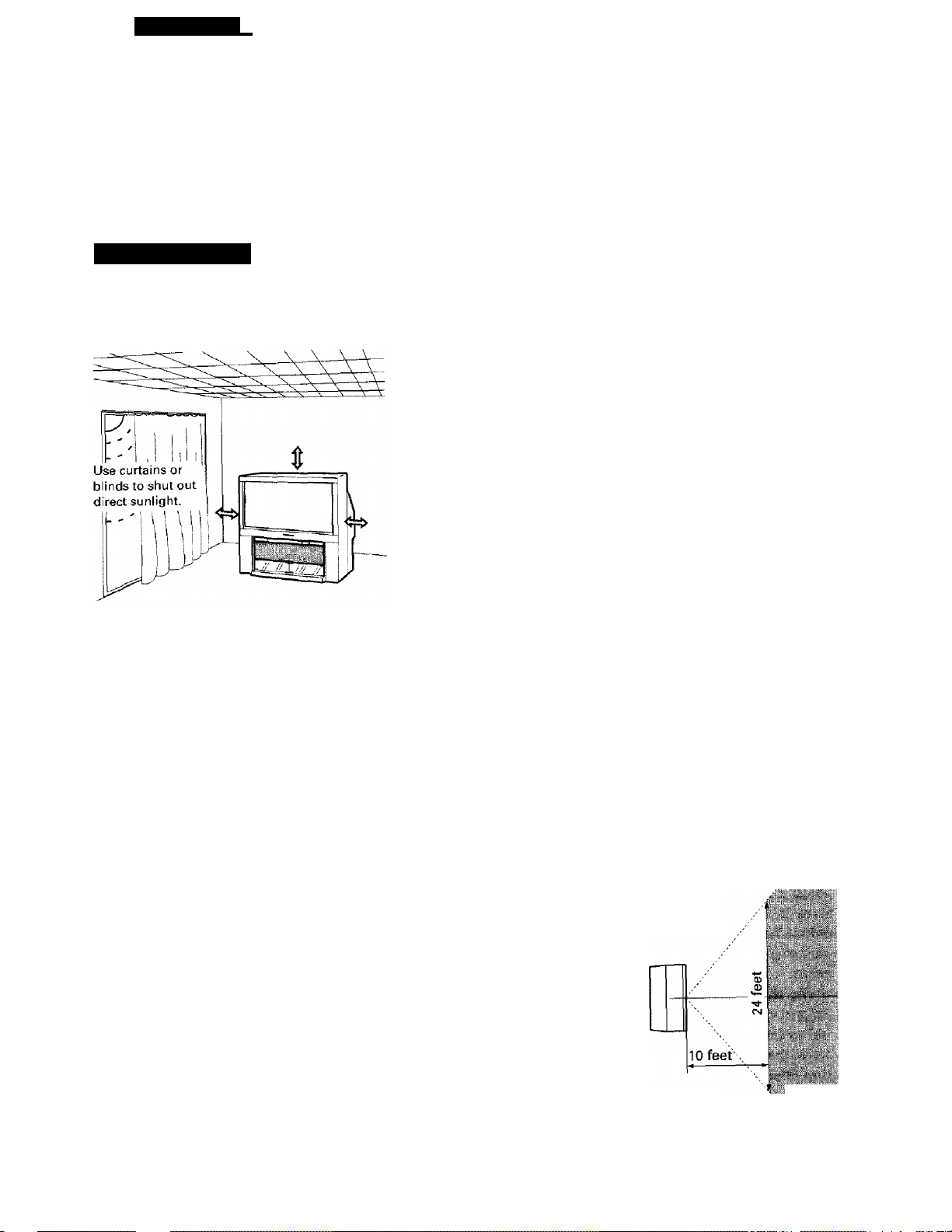
Downward spot lights or fluorescent lights in an
overhead "Honeycomb" prevent direct
illumination of the screen.
If you install the TV close to a wall, keep a
enough space (<!=>; 10 inches or more) around
the TV.
Where to install
Place the TV on the floor or on a sturdy platform. The mounting
surface should be flat and steady. When placing the TV on a
soft floor, make sure that the floor is not damaged by the
weight of the TV.
Air Circulation
Place the TV far enough from the walls to allow proper
ventilation. This will prevent the TV from overheating and avoid
possible damage to the TV. Avoid dusty places too.
Heat Damage
Damage may occur if you leave the TV in direct sunlight or near
a heater. Avoid places subject to extremely high temperatures
or humidity, or to temperatures of 41°F (5°C) or lower.
Power Supply
Plug into an electrical outlet with standard household power
(120 volt AC, 60 Hz). Do not change the plug's safety prong. See
page 2.
Moisture Condensation
If the room temperature suddenly rises (or if the TV is moved
from a cool place to a hot place), dew condensation may occur
on the lenses, resulting in picture distortion or color fading. In
such a case, simply wait a while (with the power on) and the
dew will disappear.
Best Viewing
Position the TV approximately 10'25 feet away. Sitting too far to the left or right of the screen will cause the picture to
appear dull as will direct sunlight and/or room lights. Turn the TV off to check for reflections on the screen. Then
remove any source of reflections when viewing.
VERTICAL VIEWING
ANGLE [SIDE VIEW]
10 feet
»• Viewing Range
HORIZONTAL VIEWING
ANGLE [TOP VIEW]
|i|l Viewing Range
Page 5
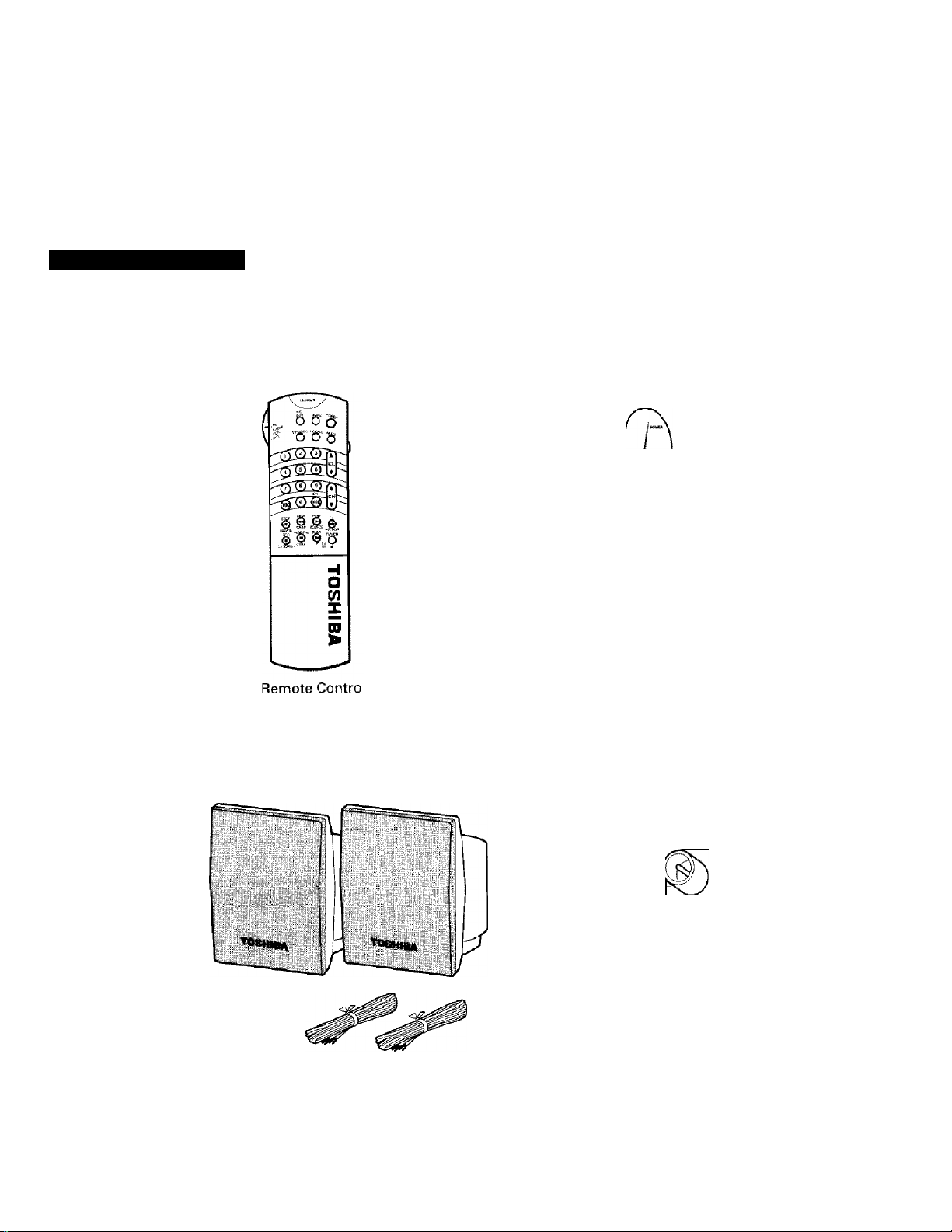
Supplied accessories
i When you unpack the package, be sure that it contains all the accessories (shown below).
//
(îSa ^
2
O
Û
§
O
Two "AA" size
alkaline
batteries
o o o o
o o a o
Template
ss j®
Two "AAA"
size batteries
EZ Remote Control*
* The instructions for the EZ
Remote Control are on the
separate sheet enclosed in this
accessory package.
©
©
O
Ô
o
ri/
Surround Speakers with cables
Antenna Adapter
________
Page 6
CHAPTER 1 I INTRODUCTION
Installation
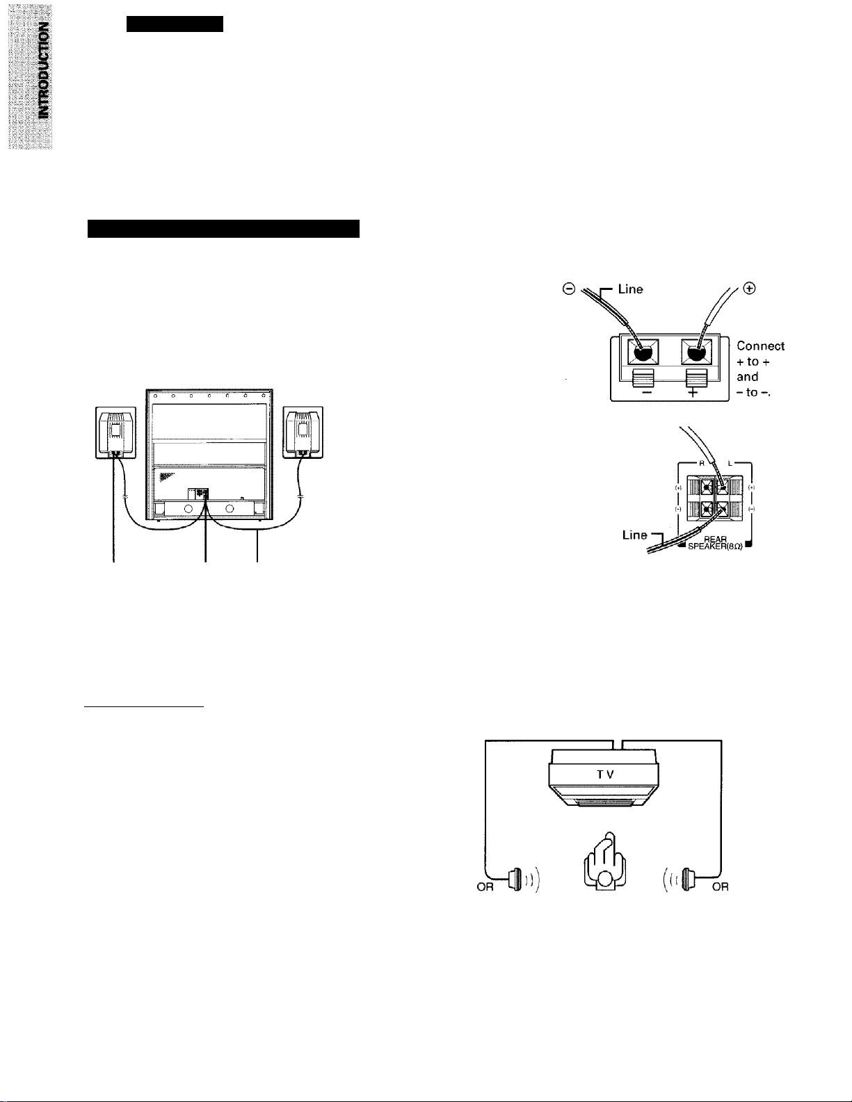
• The Surround Speakers are packed in a separate box inside this container. Unpack the Speakers
carefully and set them up as shown below.
{continued)
To set up the Surround Speakers
Connection
Connect one end of the
1
speaker cable to the
terminals on the Surround
Speaker.
TV rear
Connect the other end of the speaker
cable to the "REAR SPEAKER"
terminals* * on the TV rear panel.
While depressing the button, insert
the cable. Then, release the button.
1
Mounting position
To enjoy the sound of the DSP Surround or Dolby Pro
Logic Surround features, you must mount the speakers
to the left and right, on a shelf or on a wall behind your
normal viewing position. See page 39 for details.
Note;
You can get the best surround performance when you
install the speakers slightly above your viewing position
while watching TV.
CAUTIONS
* If the speakers are mounted on a wall, hang them
from the opening provided on their back panels.
• Care should be taken when choosing speaker
mounting hardware to insure compatibility with the
material of the wall. Do not use mounting hardware
with thin and/or soft wall materials, as the speaker
may fall and cause personal injury or be damaged.
♦Note;
The REAR SPEAKER terminals can
be used only for the supplied
speakers.
Do not connect any other speakers to
these terminals.
Connect another speaker following
steps 1 and 2 above.
L speaker
R speaker
Page 7
CHAPTER 1
I INTRODUCTION
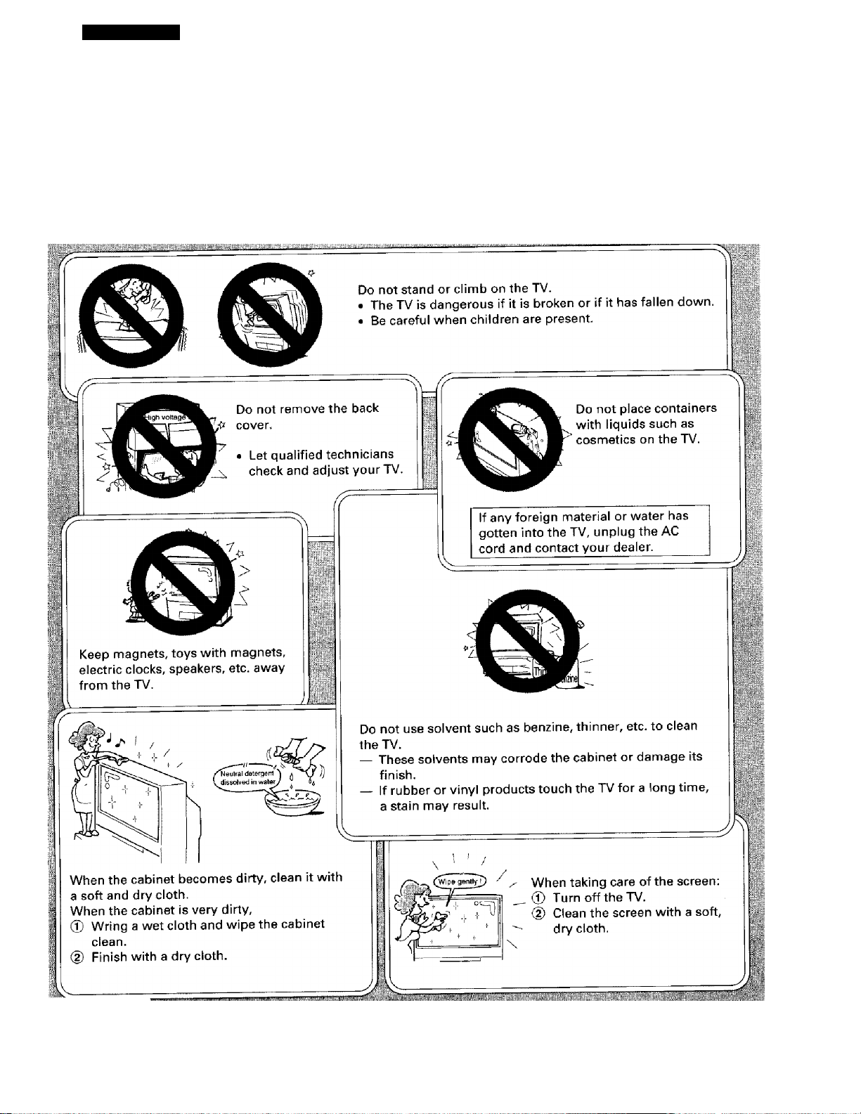
Care and Maintenance
Page 8

CHAPTER 1
I
Antenna/Cable TV
INTRODUCTION
Connection
• You can use either an indoor or outdoor antenna to receive VHF and/or UHF channels.
• Channels 2-13 are VHF channels, and channels 14-69 are UHF channels.
• We recommend using an outdoor antenna for better picture quality.
• You can receive Cable TV by contacting your local cable company.
• Cable TV delivers both VHF and UHF channels and other channels not available to
your antenna.
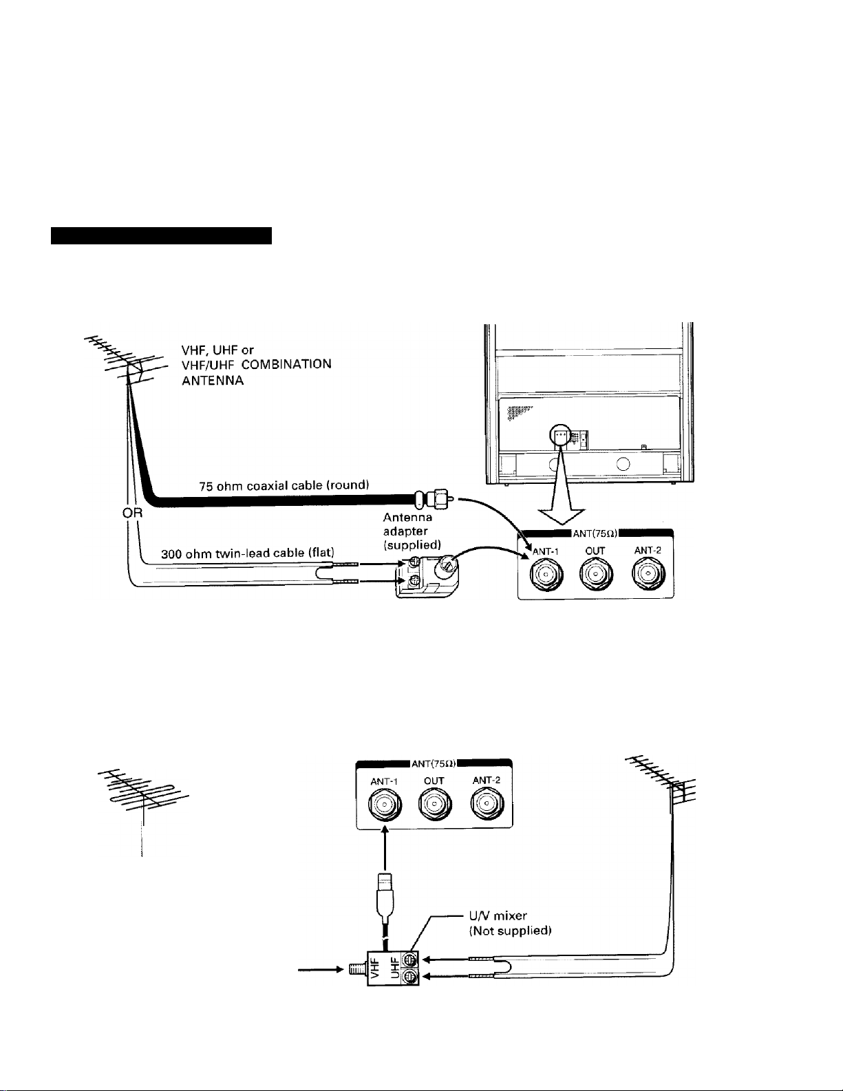
Types of antenna cables
Shown below are two basic types of antenna cables.
Signals from a home antenna may be conveyed by either type. Cable TV
signals will always be conveyed by a 75 ohm coaxial cable.
@ A 75 ohm coaxial cable is generally a round cable with F-type
connectors that can easily be attached to a terminal without tools.
Optional F-type connector
@ A 300 ohm cable is a flat "twin-lead" cable that can be attached to a
terminal through an antenna adapter supplied as an accessory.
Antenna connection panel
There are two separate 75 ohm F-type connector terminals and a
converter output terminal as shown below.
TV rear
IANT(75£2)I
ANT-1 OUT ANT-2
The ANT-1 and ANT-2 terminals are for connecting a VHF/UHF antenna
or a cable TV system. The signal, which is input on the ANT-1, also is
output from the OUT terminal whenever the RF switcher in the TV is in
the ANT-2 position. You can switch between the ANT-1 and ANT-2
positions by pressing the ANT 1/2 button on the Remote Control or the
ANT/VIDEO button on the TV. See page 22.
8
Page 9
Home antenna connection
Single lead-in cable
TV rear
Note: You can connect another signal source, like a cable TV system or video game, to the ANT-2 terminal.
Refer to CAUTION on page 48.
___________________
Both VHF and UHF lead-in cables
VHF ANTENNA
Note; You can connect another signal source, like a cable TV system or video game, to the ANT-2 terminal.
Refer to CAUTION on page 48. ________________________
UHFANTENNA
Page 10
CHAPTER 1INTRODUCTION
I
Antenna/Cable TV
Connection (continued)
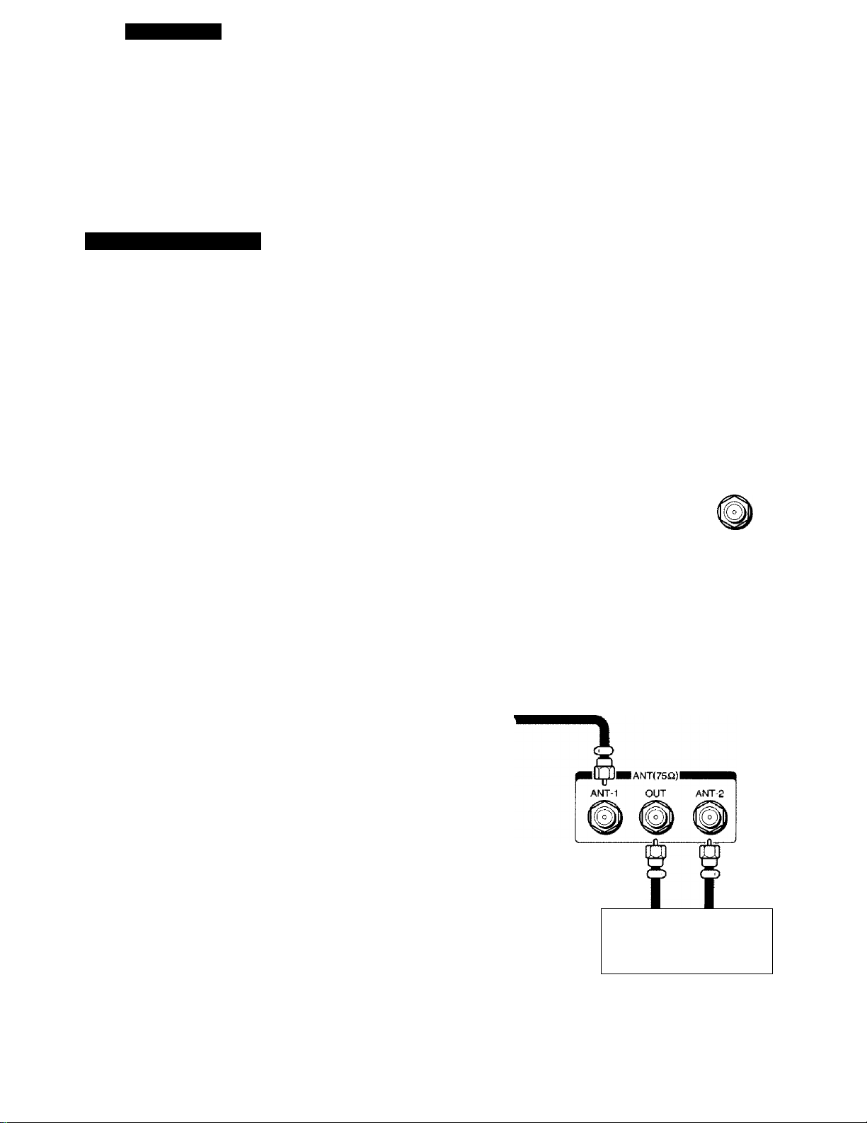
Cable TV connection
Generally, the incoming cable for a cable TV system can be connected directly to the TV antenna terminal just like a
home antenna connection. (A-1)
But some cable companies offer "premium pay channels". Since the signals of these premium pay channels are
scrambled, a cable TV converter/decoder is generally provided to the subscribers by the cable TV company. This
decoder box is necessary for normal viewing of the scrambled channels. We recommend that you consult your cable
TV company for more specific instructions on installing cable TV. (A-2)
(A-1) Cable without a decoder box (Unscrambled channels)
ANT-1 OUT ANT-2
Cable lead-in
Note: You can connect another signal source, like a cable TV system or video game, to the ANT-2 terminal.
Refer to CAUTION on page 48.
(A-2) Cable with a decoder box (Unscrambled and Scrambled channels)
• The unscrambled channels will come through the
ANT-1 terminal whenever the ANT1/2 button on the
Remote Control, or the ANTA/IDEO button on the TV,
is in "ANT 1" mode.
• The scrambled channels from the decoder box will
come through the ANT-2 terminal whenever the
ANT1/2 button, or the ANTA/IDEO button, is in "ANT
2" mode.
• Set the TV and the VCR on channel 3 or 4 to match
the output channel of the converter.
Note:
The decoding device may or may not be a part of the
cable converter.
Cable
lead-in
0C&-
IANT(75il)l
10
IN OUT
Cable TV converter/
decoder
Page 11
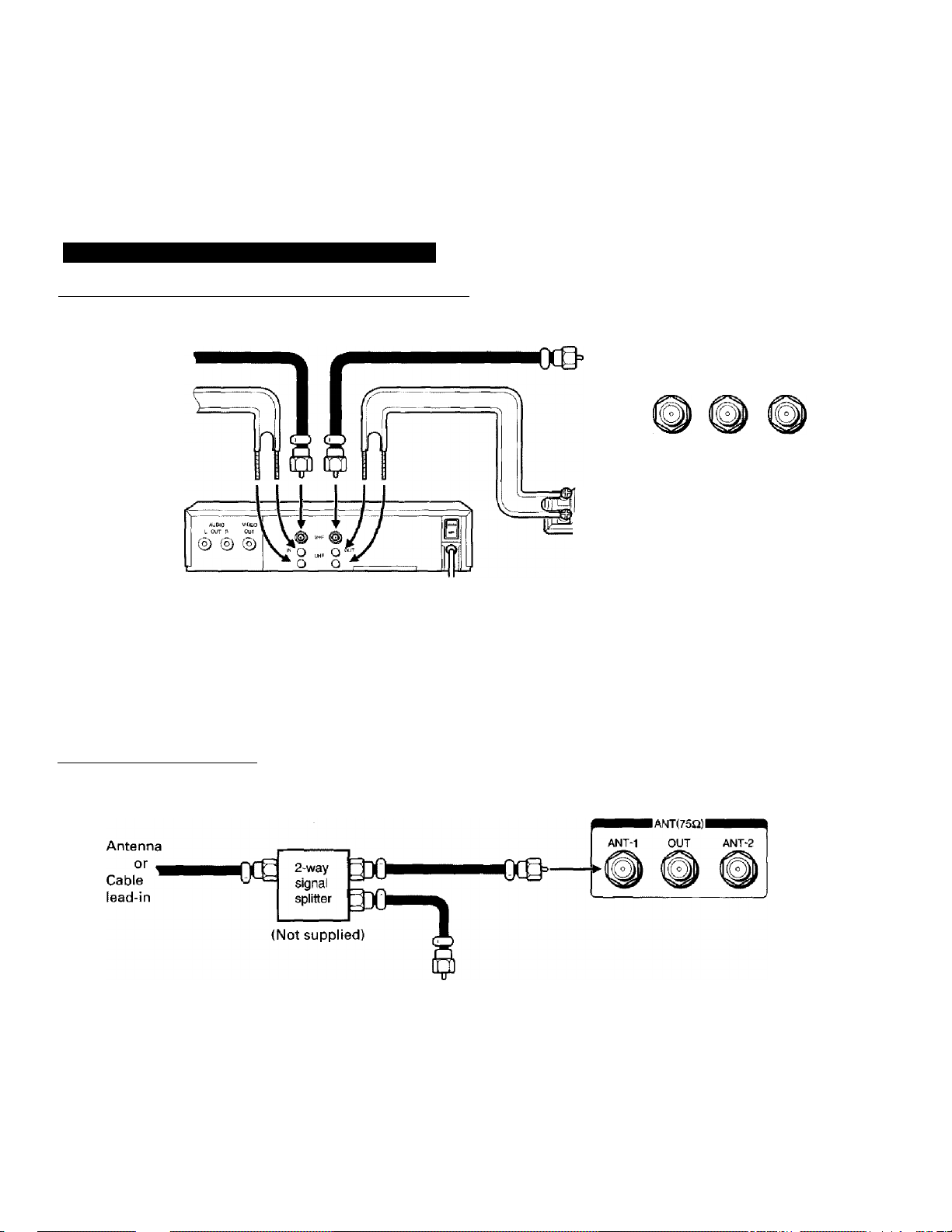
Antenna/Cable TV and VCR connections
Antenna/Cable TV connection via VCR (Simplified method)
VHF or Cable
lead-in
OR
UHF lead-in
Antenna
adapter
VCR (UA/ separated)
Notes:
• Playback of tapes may often cause the TVA/CR switching of the VCR to disconnect the antenna from the TV. If you
cannot select a certain channel, try pressing the TVA/CR button on the Remote Control.
• If you connect both VFIF and UHF lead-in cables, use a U/V mixer {not supplied). (See page 9.)
• VIDEO/AUDIO connections from the VCR to the TV are required for stereo tape playback from stereo VCR's.
IANT(75Q)I
i ANT-1 OUT ANT-2
Using a 2-way signal splitter
You can view either TV programs or VCR tapes regardless of the position of the VCR's TV/VCR switch.
______________________________________________________
AoblO V:C»Q
® ® ®
IN OUT
VCR
Note: VIDEO/AUDIO connections from the VCR to the TV are required for playback. (See page 62.)
11
Page 12
3
a
o
cc
■ wperciiion cina uonirois
• The following describes the functions of each part of the TV and the Remote Control.
For the specific use of each control, consult the corresponding page numbers in
brackets.
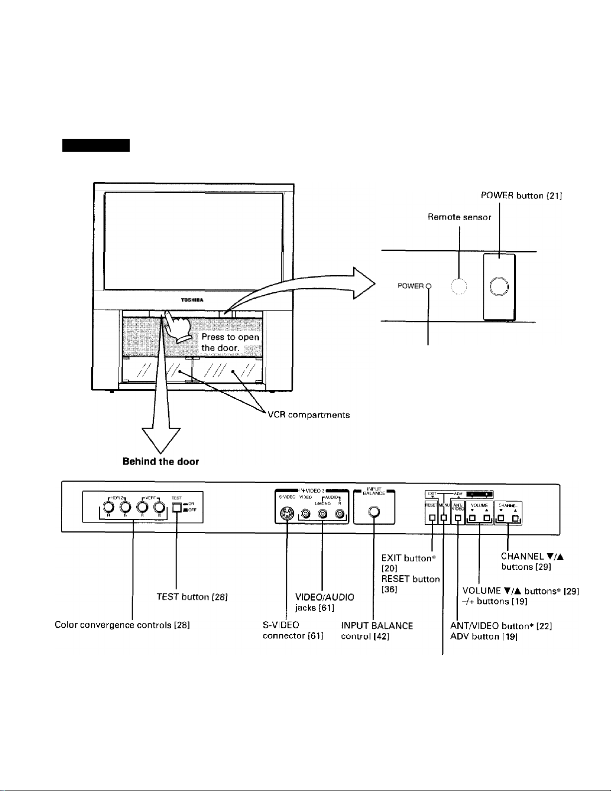
Front view
POWER indicator
12
* These buttons have dual functions.
MENU button [19]
Page 13
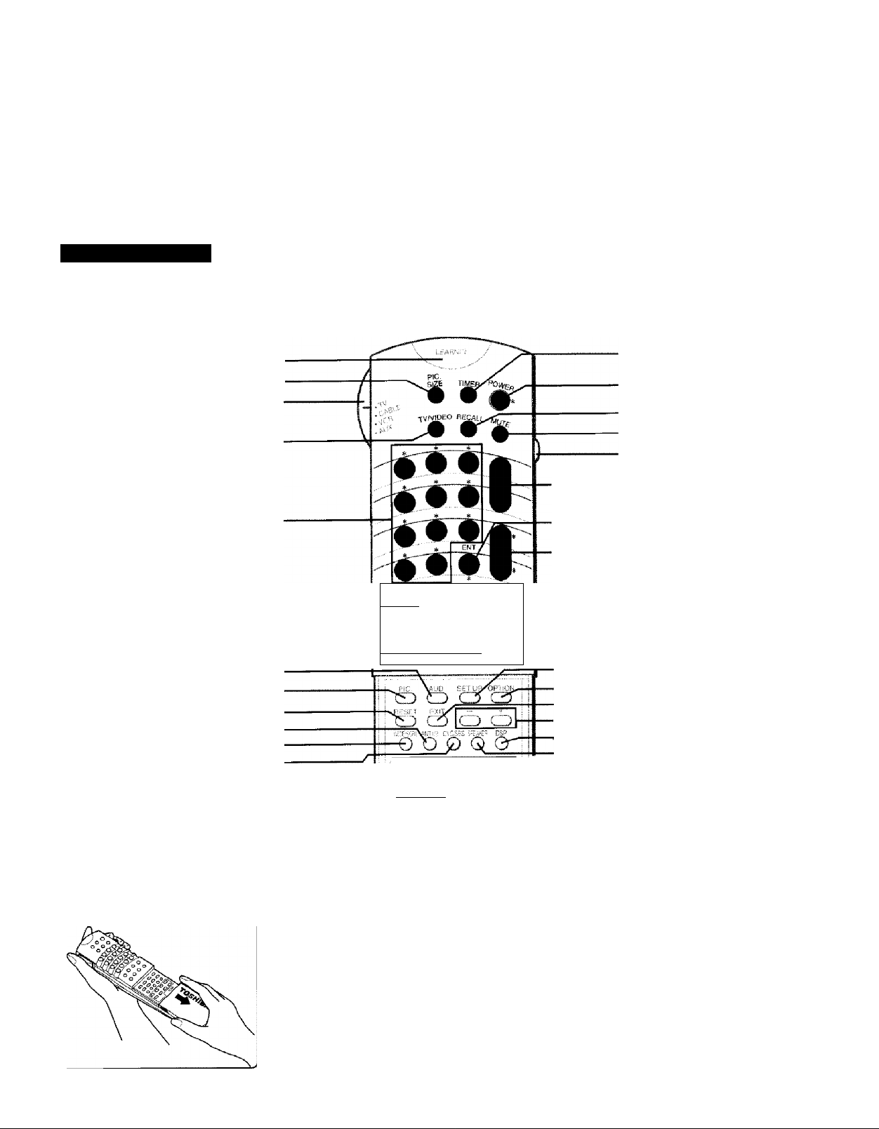
Remote Control •
• See the table on the next page, "To operate desired equipment", describing activation of specific buttons
or Mode Selection. (Refer to the owner's manual supplied with the VCR for details about the VCR
function buttons.)
LEARN indicator [18]
(Transmit indicator) p|Q SIZE [30]
Mode selection switch [14]
(TV-CABLE-VCR-AUX switch)
TVA/IDEO [621
Channel Number [29]
PiP/POP function [45]-
AUDio [20]
Picture [20]
RESET [36]
ANTV2 [22]
WIDE/SCRL[31]
CYC/SBS [44]
Learning buttons [18]
You can use these eight buttons only as
Learning function buttons. They are not
affected by Mode selection (TV-CABLE-VCRAUX).
To operate buttons inside the
cover, slide the cover down
and toward you.
----
-------------------------------------
J '
!-
[“•j
1. - ^ .
ci) cS (±) CD
cb cb cb cl
>.L>.
«bi't
il^}
1 i- 1
*© \
*0 !
■L ^ .1
o
Ui
TIMER (Sleep) [49]
POWER [21]
RECALL [331
MUTE [33]
Light switch
When you press this
VOLUME button, the 22#
A/T [29] buttons light up for
RTN/ENT [33] seconds.
CHANNEL A/T [29]
VCR function
I 1
SET UP [20]
OPTION [20]
EXIT [20]
-/+[19]
DSP [39]
SPEAKER [39]
-LEARN-USE
switch [18]
0STOP
To stop.
0REW
To rewind the
tape.
0PLAY
To play.
0FF
To fast forward.
0 REC
To record.
0 PAUSE/STILL
To pause.
0SLOW
To view a slow
motion picture.
O TVA/CR
* The 31 buttons marked with *
can be used as Learning buttons.
13
Page 14
CHAPTER 1
INTRODUCTION
Using the Remote Control
• With this Remote Control, you can operate your TV and most models of remote
controlled VCR's and cable TV converters even if they are different brands. See next
page.
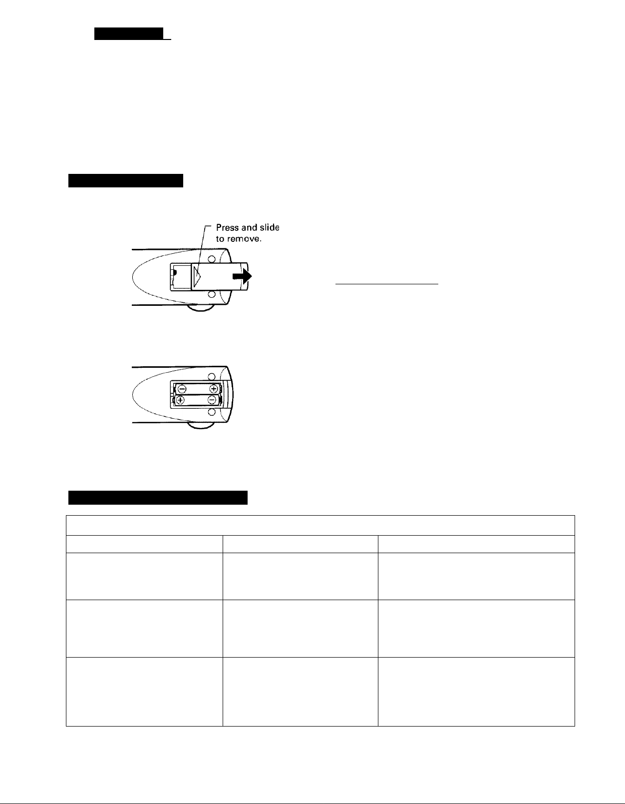
Battery installation
Place the Remote Control face down and remove
1
the battery cover.
Insert two "AA" size alkaline batteries, matching
the + and - signs on each battery with the + and
- signs of the battery compartment.
Slide the battery cover shut until the lock snaps.
CAUTIONS
• Do not throw your batteries into a fire. Dispose of
your batteries in a designated disposal area.
• Do not combine used batteries with new ones.
• Do not mix battery types.
Tips for best operation
• For optimum performance, aim the Remote Control
directly at the TV from a distance of no more than 28
feet (8.5m). Be sure there is no obstruction between
the Remote Control and the TV.
• If your Remote Control does not always adjust the TV
as you wish, you probably need to replace the
batteries. Use alkaline batteries for longer use.
• If the Remote Control will not be used for a long
period of time or when the batteries are worn out,
remove the batteries to prevent leakage.
• Do not drop, dampen or disassemble the Remote
Control.
________________________
14
To operate desired equipment
Whan you want to operate Set the Mode aalaction awiteh to You can use
TV
Cable TV Converter
VCR
Other Video/audio Equipment
(REMOTE Video Disc Players,
stereo systems or additional
VCR's, etc.)
The function buttons not listed in the table above operate the TV as usual.
TV
CABLE
VCR
AUX
all the buttons
• POWER button
. CHANNEL A/T buttons
• Channel Number buttons
• RTN/ENT button
• POWER button
. CHANNEL A/T buttons
• Channel Number buttons
• VCR function buttons
• RTN/ENT button
as Learning buttons;
• POWER button
• CHANNEL A/T buttons
• Channel Number buttons
• VCR function buttons
• RTN/ENT button
Page 15
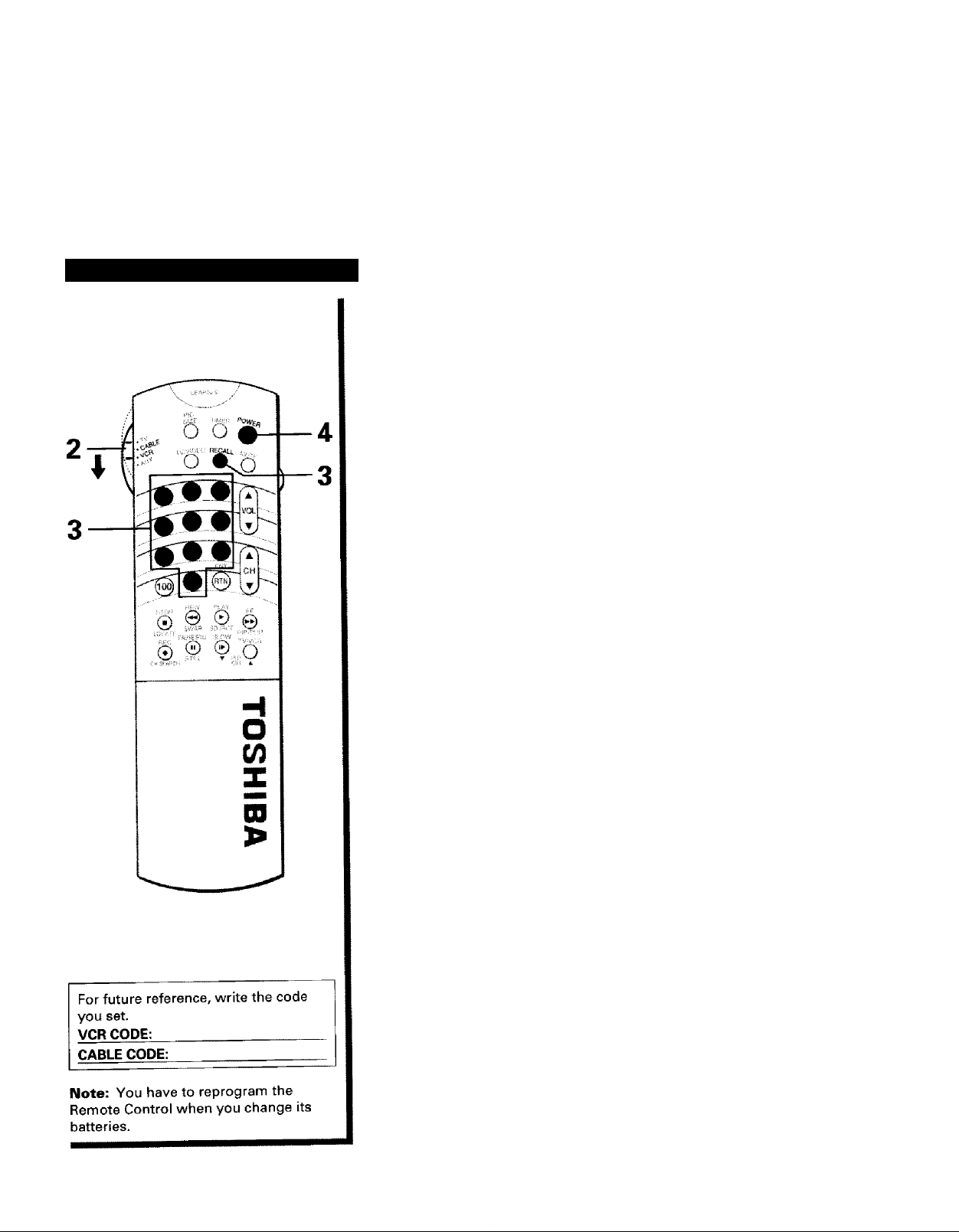
To program the Remote Control
This Remote Control is preprogrammed to operate Toshiba VCR's.
To use VCR's other than Toshiba models (or Cable converters),
perform the following procedures before operating.
When you connect several pieces of video/audio equipment to the TV,
follow the instructions on page 18.
Refer to the "VCR CODE TABLE" (or "CABLE TV CONVERTER CODE
TABLE") on pages 16 and 17 to find the code number that
1
corresponds to the brand name of your VCR (or your converter).
If more than one number is listed, try each one separately until you
find the one that works.
Set the Mode selection switch to VCR (or CABLE).
2
Hold down RECALL while pressing the Number buttons for the
three digit code number for your brand of VCR (or converter).
3
The transmit indicator lights up for 1 second when the
programming is completed.
When an operation error has occurred, the indicator blinks.
Press RECALL again to reset.
Point the Remote Control at the VCR (or at the converter) and press
POWER to test the code number.
—If the right number was entered, the VCR should turn on.
—If the VCR does not respond to the Remote Control, repeat steps
1 to 4 with another code number.
Follow the instructions on page 18 if the VCR does not respond,
even though you have programmed the Remote Control following
steps 1 to 4 above.
15
Page 16

CHAPTER 1
INTRODUCTION
Using the Remote Control
(continued)
• The code numbers listed below are the newest ones at the time of printing. New code
numbers may or may not have been added since printing.
VCR code table
BRAND NAME CODE NUMBER
Aiko..
.......................
Aiwa
.............................
Akai..............................060,068, 080, 125,
Alba
............................
Amstrad.......................019
Anitech
........................
ASA..............................056, 100
Audiovox
Baird
Bel! & Howell
Broksonic
Bush
Canon
Capehart
Carver..........................100
CCE
CGE
Cimline
Condor
Craig
Crown
Curtis Mathes
Daewoo
Dansai
Daytron
De Graaf
Deoca
Dual
Dumont
Dynatech
Eiectronic....................019
Emerson
ESC..............................297
Ferguson.....................060
Fidelity.........................019
Finlandia
Finlux
First Line
Fisher
Frontech......................039
Funai............................019
GE
GEC
General........................071
Go Video
Goldstar
.....................
............................
...................
............................
..........................
.....................
............................
.............................
........................
........................
............................
..........................
......................
.........................
.......................
......................
..........................
............................
.......................
.....................
............
.....................
..........................
.....................
..........................
................................
.............................
.....................
......................
....297
019
039, 228, 297
091
056
123
..............
123
140, 203, 230
091,228, 297
054
039
091, 297
019
091
039
066, 259
297
.............
054
039, 064, 065, 297
091
039
061
019, 100
060
019,100, 123, 124
019
.........
019, 021,056, 080,
100, 123, 129
019, 061, 100, 123,
062, 091
065, 066, 073, 085,
054, 079, 084
100
251,298
056, 057
261
140, 203, 227, 228,
230, 231.313
124
123
BRAND NAME CODE NUMBER
Goodmans
Gradiente
Graetz..........................060, 123
Granada
Grundig.......................100
Harman/Kardon
Hem
Hinari...........................091, 227
Hitachi
Imperial
Interfunk
ITT
JCL
Jensen
JVC
Kendo..........................125
Kenwood.....................057, 060, 065, 086
Lloyd
Loewe..........................056
Loewe Opta
Logik
Luxor
LXI
Magnavox
Manesth
Marantz
Marta
Matsui
MEI
Memorex
MGA
Minolta
Mitsubishi
MTC
Multitech
Murphy
NEC
Neckermann
Nikko
Noblex
Nokia
Nordmende.................060
Optonica
Orion
..................
....................
......................
..........
.............................
........................
.......................
.....................
...............................
..............................
........................
..............................
...........................
................
...........................
...........................
...............................
...................
.....................
......................
...........................
.........................
..............................
.....................
...........................
........................
..................
.............................
.....................
........................
.............................
...............
...........................
.........................
..........................
.....................
...........................
019, 039, 056, 081,
091, 297
019
065, 100, 123
057
091
019,060,061,084,
124
019
100
060, 065, 123, 125
054
060
027, 060, 086
019
100
091, 259
062,065, 125
056
019, 054, 100, 129,
168
064,091
054,057,081, 100
056
227, 228
054
019, 054, 056, 058,
065, 066,067, 123
062,080
061, 124
062, 080, 086, 100,
192, 233, 261
019, 259
019, 091
019
057, 059, 060, 069,
086
100
056
259
060,065, 123, 125,
259
067, 081
140, 227, 228
BRAND NAME CODE NUMBER
Osaki...........................019, 056, 091
Otto Versand
Pallidium
Panasonic
Penney.........................054, 056, 057, 059,
Pentax
Perdio.........................019
Philco
Philips
Phonola......................100
Pilot
............................
Pioneer
Portland
Proline........................019
Pulsar
Pye..............................100
Quartz.........................065
Quasar
Quelle
Radiola
RCA
.............................
RCA Unified
Realistic.......................019, 054, 056, 065,
Rex
.............................
Ricoh
Roadstar
Runco
Saba
Saisho
Salora
Samsung
Sansui
Sanyo............................065, 066,123, 259
SBR
............................
Schaub Lorenz
Schneider
Scott
Sears
SEI
..............................
Sentra
Sharp
Shintom
Siemens
Sinudyne....................100
.............
...................
...................
.........................
.........................
.........................
.......................
.....................
.........................
........................
.........................
......................
..............
..........................
.....................
.........................
...........................
.........................
...........................
....................
.........................
...........
.....................
............................
.............................
.........................
..........................
.....................
......................
100
091
054, 096, 244
061, 259
061,084, 124
054
054,081, 100, 129
056
086, 100
039
058
054, 115
100
100
054,061,084,096,
124, 168, 221
079
066, 067, 081, 085,
123, 259
060
053
056, 091, 259
058
060
227, 228
062, 065,125
064, 259
060, 086
100
019, 060
019, 091,100, 129
064, 140, 203, 229,
231
054, 056, 061,065,
066, 073, 085, 123,
124
100
039
067, 081
091
056, 123
16
Page 17

Cable TV converter code table
BRAND NAME
Sony
.......................
STS..........................
Sunstar
...................
Sylvania
Symphonic
Tashiko
Tatung
Teac.........................
Technics
Teknika....................
Telefunken
Tenosal
Tensai
Thomson................. ...060
Thom
Toshiba
Totavision
Triumph
Unitech
Universum
Vector Bsearch
Victor
Video Concepts....
Videosonic
Wards
Yamaha
Yoko
Zenith
..................
.............
...................
.....................
.................
.............
...................
.....................
.......................
...................
.............
..................
...................
.............
.......................
.............
......................
...................
.......................
.....................
CODE NUMBER
...051,052, 053, 054
...061
...019
. ..054, 062, 100, 129
...019
...019
...019, 060,100
...019, 060
...054
...019, 054, 056,071
...060, 206
...091
...019
...060
...060, 062, 064, 086,
229, 231,385
...056, 259
...227
...259
...019, 056, 068, 100,
125
...057, 059
......
...027, 060, 086
...059, 080
...259
...019, 054, 061,066,
067,081,091, 168,
231, 259
...057.060
...259
...052, 053, 058
BRAND NAME
ABC
........................
Archer
....................
Century
..................
Citizen
....................
Colour Voice
Comtronics............ ....059, 079
Eastern
Garrard
Gemini
General
Instrument
Hamlin.................... . ..028, 039, 278, 292
Hitachi.................... ....030
Jasco .....................
Jerrold.................... ....022, 030, 031,033,
Wacom
Magnavox
Wemorex...................
Movie Time
NSC
........................
Oak.......................... ....026, 038
Panasonic
Paragon
Philips.................... ....044, 046, 047,048,
Pioneer
Pulsar
PVP Stereo
Visual Matrix ...
RCA
........................
Regal...................... ....039, 278, 292
Regency
Rembrandt
Bunco
Samsung
Scientific Atlanta
Signal
Signature
SL Marx
Sprucer
Standard
Components
Starcom
Stargate
STS..........................
Tocom
Toshiba
........
.................
..................
...................
.........
..................
..............
............
.............
.................
..................
.....................
................
............
....................
...............
.....................
...............
.................
..................
..................
..................
....................
..................
CODE NUMBER
. ..026,030, 032,036
....058, 172
....172 United Cable
....172
....044, 050 Viewstar
....021
....172
....034, 089
....030
....172
034, 043, 045
....052
....046
....019
....175
....089, 175
....040
....019
049, 050, 079
.,..163
....019
...022
...040
,...021
....089
....019
...059, 163
,...025, 027, 036, 296
...,034,059
....030
...,059
....040
,...174
.......
.. .022, 034
....034,059
....175
....031, 032, 078
.,.,019
BRAND NAME CODE NUMBER
Unika
......................
United Artists
Universal
Zenith
................
..................
.....................
...172
.........
...026
..........
...022
...058, 096, 172,210
...046, 079
...019
17
Page 18
CHAPTER 1 INTRODUCTION
I
Using the Remote Control
(continued)
• This Remote Control is capable of learning operating codes from most infrared remote
control transmitters. You can control the functions of your TV and a variety of video/
audio equipment with the supplied Remote Control only.
• The 31 buttons can be used as Learning buttons. {See page 13.)
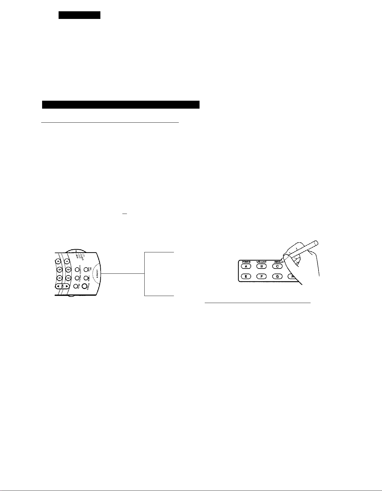
To program the Remote Control (continued)
To learn operating code of another remote control
Set the Mode selection switch to AUX.
1
6 5" S'
’oC-t' tV/ViPEO B^Li
Set the LEARN-USE switch to LEARN.
' TIUSE
Place the supplied Remote Control and the remote
control transmitter to be learned, head to head
approximately 1 to 3 inches (3 to 8cm) apart.
Supplied Remote Control
LEARN
Head to head
1-3 inches apart
Remote to be learned
)
iO-QD
□ Q
□ a
IQ
Set the LEARN-USE switch to USE.
LEARN [dO USE
To check your programming, operate the
appropriate equipment with the supplied Remote
8
Control. If the equipment does not operate as
expected, repeat steps 1 to 7.
If needed, try changing the distance between the
two remote controls.
Attach the supplied template to the Remote
Control to enter the function names of the AUX
buttons you have programmed.
Use a ballpoint pen etc. to write the function
names.
To cancel the learned operating codes
18
Hold down the button to learn on the supplied
Remote Control for about 1 second until the
LEARN indicator lights up.
Note:
When you press a button other than Learning
button, the indicator will blink. For specific
Learning buttons in specific modes, see the table
"To operate desired equipment" on page 14.
Hold down the function button to be learned on
the remote control transmitter for about 3 seconds
until the LEARN indicator goes off.
Note:
If the LEARN indicator goes off after blinking, the
supplied Remote Control cannot learn the
operating code or an error has occurred. Try steps
4 and 5 again.
Repeat steps 4 and 5 for other function keys.
Set the Mode selection switch to AUX.
1
Set the LEARN-USE switch to LEARN.
2
Hold down the button of the function to cancel on
3
the Remote Control for about 1 second until the
LEARN indicator lights up.
Hold down RECALL and RESET at the same time
for about 6 seconds until the LEARN indicator goes
off after blinking.
Note:
You cannot cancel the programming if you release
the button while the indicator is blinking.
Set the LEARN-USE switch to USE.
Page 19
CHAPTER 1
INTRODUCTION
Quick Reference Menu Guide
• We recommend that you familiarize yourself with these procedures for using the Menu
function.
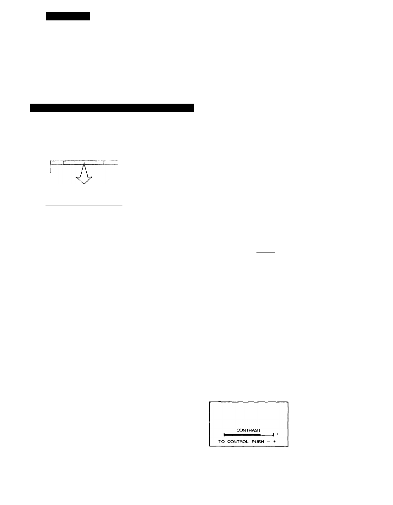
To use the menu function buttons on the TV
MENU button
Each time you press MENU, the PICTURE, AUDIO, SET UP or OPTION
menu on-screen display is selected in order.
P1GTURE
CONTRAST
BRIGHTNESS
COLOR
TINT
SHARPNESS
FLESH TONE
MEN U
ADV
V
-/+
PICTUBE PREFERENCE
TO SELECT
TO CONTHOl
AUDIO
MTS
BASS
TREBLE
BALANCE
SPEAKERS
TO SELECT
TO CONTROt
SET UP
AUTO CH PFCX^AM
ADD•ERASE
TV CABLE
CH PROGRAM
CH CAPTION
CH LOCK
CLOSED CAPTION
TO SELECT
TO CONTROL
OPTION
LANGUAGE
DEMONSTRAT I ON
NOISE REDUCTION
PIP CONTRAST
3D-Y C SEPARATION
Notes:
• The on-screen instructions will appear
under each menu display for easy stepby-step operation.
• The ADV button on the TV functions as
the ANTA/IDEO button when no menu
display is on the screen.
• The -/+ buttons on the TV function as
the VOLUME A/T buttons when no
menu display is on the screen.
• The EXIT button on the TV functions as
the RESET button when there is no on
screen display.
On-screen instructions ■
TO SELECT MENU PUSH ADV
TO CONTROL PUSH - +
ADV button
Use the ADV button after you have pressed MENU to select the function
you want to adjust.
Each time you press ADV, the function to be adjusted will be selected in
numerical order.
The selected function will be displayed in magenta.
-/+ buttons
Use the -/+ buttons after you have pressed ADV or any of the four menu
buttons (PICTURE, AUDIO, SETUP or OPTION).
Example: CONTRAST adjustment mode display
Pressing + increases the picture contrast.
Pressing - decreases the picture contrast.
19
Page 20
CHAPTER 1 INTRODUCTION
I
Quick Reference Menu Guide
(continued)
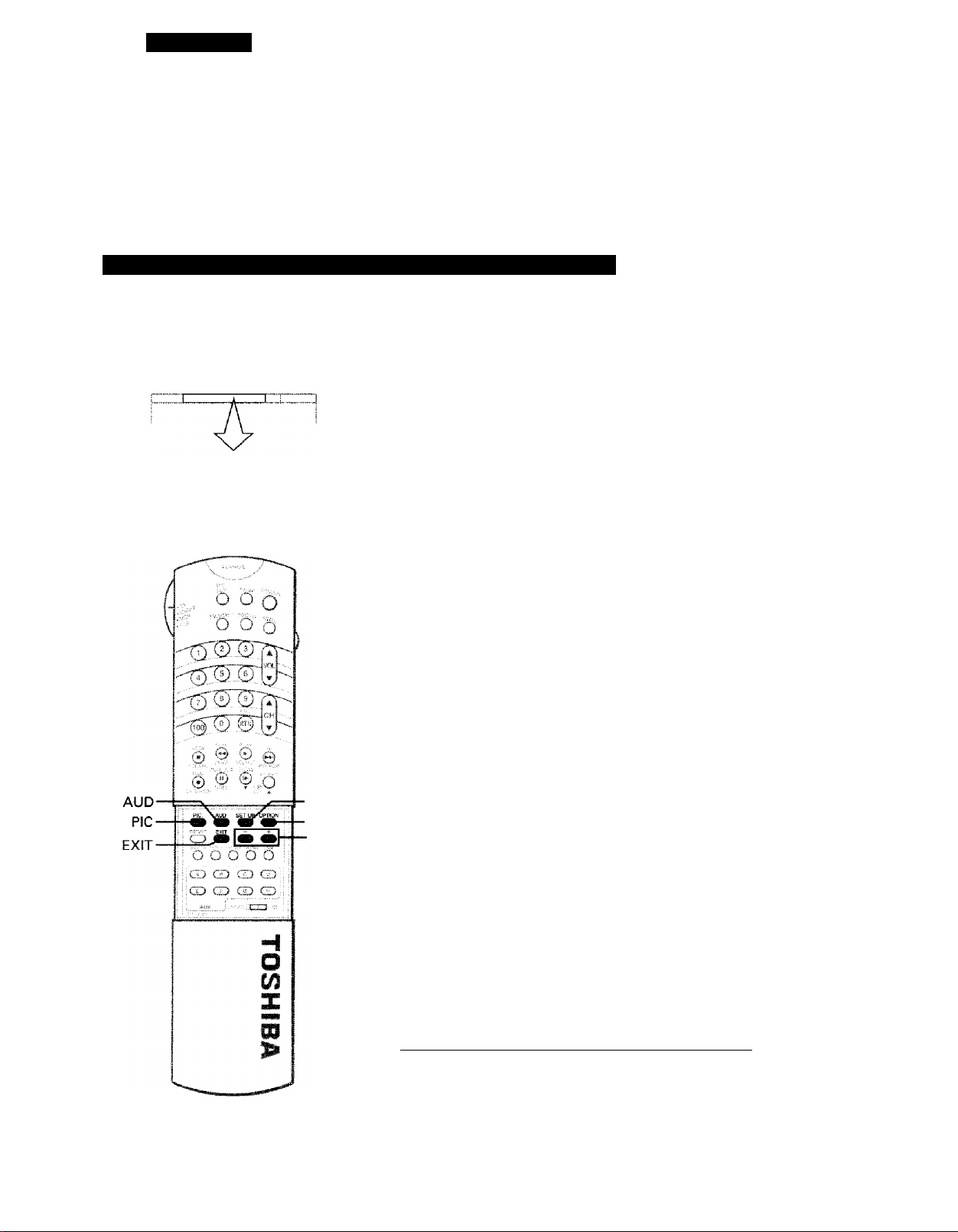
To use the menu function buttons on the Remote Control
PIC(TURE) button
□□□□□□
f
EXIT
■SET UP
■OPTION
—!+
Press PIC repeatedly until the PICTURE
menu function you want to adjust is
selected.
The selected function will be displayed in
magenta, then press -/+ to adjust the
setting.
Details for each function begin on
page 34.
AUD(IO) button
Press AUD repeatedly until the AUDIO
menu function you want to adjust is
selected.
The selected function will be displayed in
magenta, then press -/+ to adjust the
setting.
Details for each function begin on
page 37.
SET UP button
Press SET UP repeatedly until the SET UP
menu function you want to adjust is
selected.
The selected function will be displayed in
magenta, then press -/+ to adjust the
setting.
Details for each function begin on
page 23.
OPTION button
PICTURE
CONTRAST
BRIGHTNESS
COLOR
TINT
SHARPNESS
FLESH Ti>fe
PICTURE PREFERENCE
TO SELECT NENU
PUSH p I c
TO CONTROL PUSH - +
AUDIO
MTS
BASS
TREBLE
BALANCE
SPEAKERS
TO SELECT MENU
PUSH AUD
TO CONTROL PUSH -
SET UP
AUTO CH PROGRAM
ADD■ERASE
TV CABLE
CH PROGRAM
CH CAPTION
CH LOCK
CLOSED CAPTION
TO SELECT MENU
PUSH SET UP
TO CONTFtOL PUSH - +
20
Press OPTION repeatedly until the
OPTION menu function you want to adjust
is selected.
The selected function will be displayed in
magenta, then press -/+ to adjust the
setting.
Details for each function begin on
page 51.
OPTION
LANGUAGE
DEMONSTRATION
NOISE REDUCTION
PIP CONTRAST
3D-Y C SEPARATION
TO SELECT MENU
PUSH OPTIOvI
TO CONTROL PUSH -
EXIT button (on the TV and on the Remote Control)_____________
The above four menu displays will automatically disappear from the
screen if no control has been operated for about 15 seconds, and all
other menu displays also disappear after about 6 seconds.
If you want to clear the screen of all on-screen displays instantly, press
EXIT.
Page 21
CHAPTER 2
GETTING STARTED
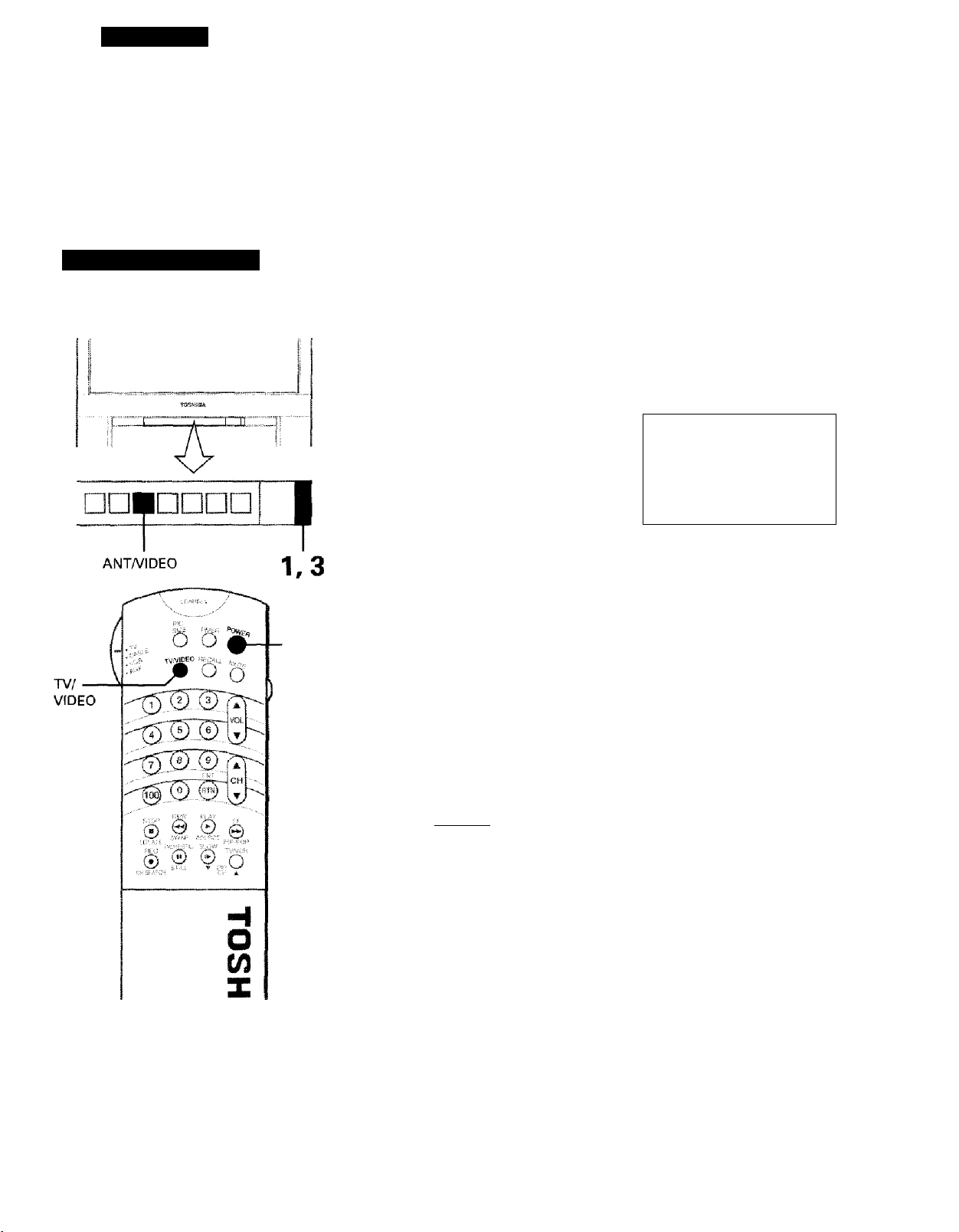
Turning the TV On/Off
To turn the TV on/off
First set the Mode selection switch on the
Remote Control to TV.
1,3
Press POWER on the Remote Control
1
or the TV.
The picture will appear in a few
seconds.
The following on-screen information
will be displayed for a few seconds.
• Antenna mode (when in TV mode).
• Channel number or VIDEO mode
selected.
• Channel caption (if previously preset).
• Stereo or SAP audio status.
To turn the TV off, press POWER
again.
STEREO
SAP
Auto-Power-Off
if a vacant channel is selected, or the TV broadcast for a day is
finished, the TV will automatically turn off after about 15 minutes.
This Auto-Power-O ff ie at ur e does not operate in the VIDEO mode.
ANT 1
ABCD
TV 4
Note: The TVA/IDEO button or ANT/
VIDEO button is used to input
signals from other sources, like
VCR's or Video Disc Players,
connected to this TV.
See pages 22 and 62 for details.
Last Mode Memory
If the power is cut off while you are viewing the TV and the power is
resupplied, the TV is turned on automatically by the Last Mode
Mem ory featu re . If the power is going to be off or when you leave
home for a long time, unplug the power plug from the wall outlet to
prevent the TV from turning on in your absence.
21
Page 22
CHAPTER 2
GETTING STARTED
Turning the TV On/Off
(continued)
• Your TV has two separate antenna inputs (ANT-1 and ANT-2) that allow you to connect
two different signal sources, if desired.
I
H”
w
a
W
U1
(9
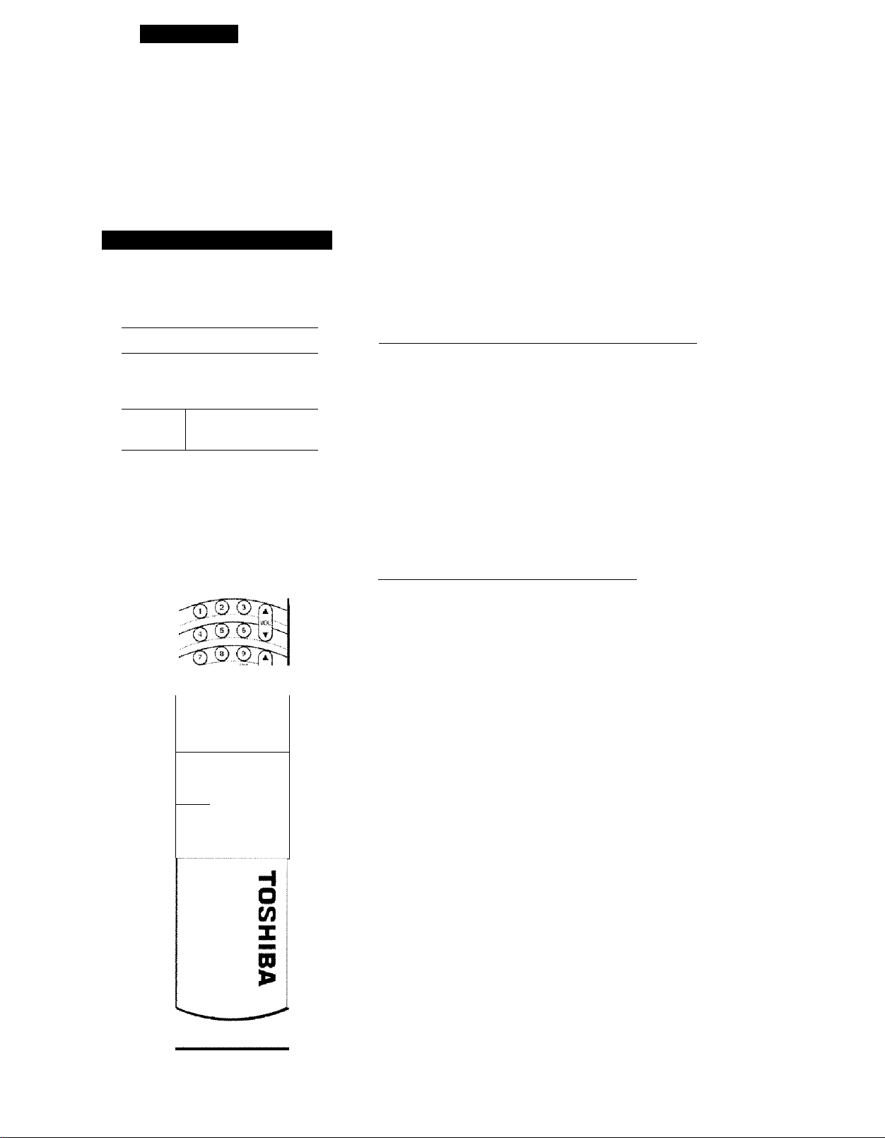
To select the antenna input
You can switch back and forth between the two signal sources by
pressing the ANT1/2 button on the Remote Control or the ANTA/IDEO
button on the TV,
ANT1/2 •
I
ANT/VIDEO
TOSWSBA.
I
1 '
5 5'o^
d Ò 5
©
©
0
©
©
O o o !
Q
o o
h o o Q
, o
CD
cd' 'CDCD ' i
■
CD CD CDGD,
è
o
-1 i
CD
^
Using the ANT 1/2 button (on the Remote Control)
Each time you press the button, the ANT 1
mode and ANT 2 mode will alternate.
The selected mode will be displayed in
magenta to show which antenna source
you are watching.
Select the mode that matches the antenna
terminal you use.
Note:
This button does not function in the
VIDEO mode. See page 62 for details on
using the VIDEO modes.
Using the ANT/VIDEO button (on the TV}
Each time you press the button, the ANT
1, VIDEO 1, VIDEO 2, VIDEO 3 or ANT 2
mode will be selected in order.
The selected mode will be displayed in
magenta to show which signal source you
are watching.
Press the button until "ANT 1" or "ANT 2"
is displayed in magenta to match the
antenna terminal you use.
Note:
This button functions as the ADV button
while any of four menu displays
(PICTURE, AUDIO, SET UP or OPTION) are
on the screen.
TO SELECT PUSH ANT 1 £
VIDEO 1
VIDEO £
VIDEO 3
TO
SELECT PUSH ANT VIDEO
____________
ANT 1
ANT 2
ANT 1
ANT 2
22
Page 23

CHAPTER 2
GETTING STARTED
Programming Channels
• First, use the AUTO CHANNEL PROGRAM function to preset aii active channeis in your
area automaticaliy.
If necessary, arrange the preset channels with the CHANNEL PROGRAM and ADD/ERASE
functions so that you can tune into only desired channels.
AUTO CHANNEL PROGRAM function
To program all available channels automatically (AUTO CH PROGRAM)
Press POWER on the Remote Control
1
or the TV to turn on the TV.
ANT 1
CABLE 4
1
2,3
4
Press SET UP on the Remote Control
(or MENU on the TV) to display the
SET UP menu on the screen.
Press SET UP repeatedly on the
Remote Control (or ADV on the TV)
until “AUTO CH PROGRAM" is
displayed in magenta.
Press - or + to start
autoprogramming.
The TV will automatically determine
whether the TV (antenna), STD
CABLE , HRC CABLE, or IRC CABLE
signals are being received.
Then automatically cycle through all
channels and place active channels
in the channel memory.
When autoprogramming is
complete, you will see the message
at the right.
You can check to see which channels
are in memory by pressing
CHANNEL A or T.
SET UP
AUTO CH PFWDGRAM
ADD■ERASE
TV • CABLE
CH PROGRAM
CH CAPTION
CH LOCK
CLOSED CAPTION
TO SELECT ^ENU
PUSH SET UP
TO CCWTROL PUSH - +
OFT i IP
AUTO CH PROGRAM
ADD•ERASE
TV-CABLE
CH PROGRAM
CH CAPT1 ON
CH LOCK
CLOSED CAPTION
TO SELECT MENU
PUSH SET UP
TO CONTROL PUSH - +
AUTO CH PROGRANMING
FINI SHED
CABLE 4
23
Page 24

CHAPTER 2 GETTING STARTED
Programming Channels (continued)
• If the AUTO CH PROGRAM function does not memorize any certain CABLE channels,
follow the "CHANNEL PROGRAM function" instructions below. (You will probably not
need to use this function.)
in
o
lU
CM
CHANNEL PROGRAM function
MENU
To program channels of a specific TV/CABLE mode
(TV. CABLE) (CH PROGRAM)
Press SET UP on the Remote Control
1
(or MENU on the TV) to display the
SET UP menu on the screen.
Press SET UP repeatedly on the
Remote Control (or ADV on the TV)
until "TV*CABLE" is displayed in
magenta.
Press - or + until the mode that
corresponds to your TV signal
system is displayed in magenta.
Each time you press the button, the
TV, STD CABLE, HRC CABLE or IRC
CABLE mode will be selected in
order.
SET UP
AUTO CH PF03RAM
ADD ERASE
TV■CABLE
CH PROGR««
CH CAPTION
CH LOCK
CLOSED CAPTION
TO SELECT MENU
PUSH SET UP
TO CONTROL PUSH - +
Cicrx I IP
" AUTO CH FT^OGRAM
ADD F.RASE
TV-CABLE
CH HHCXtHAM
CH CART f ON
CH L.OCK
CLOSED CAPTiCW
TO SELECT MENU
PUSH SET UP
TO CONTROL PUSH -
TV
STD CfiSLE
HRC C^LE
IRC C^LE
TO SELECT PUSH - +
24
8
SET UP
3,6
Tuning band and Receivable channels
Tuning band Receivable channels
TV broadcast
STD CABLE*
HRC CABLE*
IRC CABLE*
* Vour cable company can advise you as to which system they are
using.
VHP: 2-13
UHF: 14-69
** 1-125
(Number on this TV)
Page 25

CHANNEL PROGRAM function (continued)
Press SET UP on the Remote Control
(or MENU on the TV) again to
display the SET UP menu on the
screen.
Press SET UP repeatedly on the
Remote Control (or ADV on the TV)
until "CH PROGRAM" is displayed in
magenta.
SET UP
AUTO CH PROGRAM
ACMD • ERASE
TV CABLE
CH PROGRAM
CH CAPTION
CH LOCK
CLOSED CAPT I ON
TO SELECT MENU
PUSH SET UP
TO CONTROL PUSH ~ +
SET UP
' ' AUTO CH PROGRA^.^
ADO ERASE
TV CABLE
CH PROGR^yv!
CH CAPT i ON
CH LOCK
CLOSED CAPT)ON
TO SELECT MENU
PUSH SET UP
TO CONTROL PUSH - +
CABLE channel reference chart
Number on
thisTV
Correifinnd-
ing CABLE
cfaamwl
1
5
6 A-6
14
15
A-8 67 67
A-7 68
NumlMr on
Uric TV
69 69
A
B 92 92
Corr««pandmg CABLE
68
w
a
UJ
o
Press - or + to start channel
programming. The TV will
automatically cycle through all the
TV or CABLE channels in the mode
selected by the TV*CABLE function
and store active channels in the
channel memory.
When channel programming is
complete, you will see the message
at the right.
Press CHANNEL A or T to make
8
sure the channel programming has
been done properly.
To change the tuning band for the small picture (PfP/POP)
The TV«CABLE function only works with the main picture.
Press PIP/POP ON OFF to display the small picture.
1
16 C
34
35
36
37 AA
38
60 XX
61
62 ZZ
63
64 BBB 124 124
65
66
U 95 A-5
V
w
BB
YY
AAA
65
66
93
94 94
96
97 A-3
98 A-2
99 A-1
100 100
101 101
102 102
123
125 125
93
A-4
123
Press SWAP to switch the main and small picture.
2
Change the tuning band following the steps 1 to 3 on the previous
3
page.
The above chart is typical of many cable
system channel allocations. If in doubt,
consult your cable company.
25
Page 26

CHAPTER 2 GETTING STARTED
a
§
E
o
Programming Channels
ADD/ERASE function
-/+
ADV
MENU CHANNEL A/T
To erase unnecessary channels
Select the channel to be erased with
1
CHANNEL A or T.
Press SET UP on the Remote Control
(or MENU on the TV) to display the
SET UP menu on the screen.
(continued)
SET UP
AUTO CH PROcaaAM
ADD■ERASE
TV CABLE
CH PROGRAM
CH CAPTIOM
CH LOCK
CLOSED CAPTION
TO SELECT MENU
PUSH SET UP
TO CONTROL PUSH “
■ CHANNEL
A/T
■ SET UP
-/+
Press SET UP repeatedly on the
Remote Control (or ADV on the TV)
until "ADD«ERASE" is displayed in
magenta.
Press - or + until "CH ERASE" is
displayed in magenta indicating that
the channel has been erased from
the memory.
Repeat steps 1 through 4 for other
channels.
SFT UF='
AUTO CH PROt^AM
ADD•ERASE
TV - CABl. F
CH PRCX5RAM
CH CAPT1 ON
CH LOCK
CLOSED CAPTION
TO SELECT MENU
PUSH SET UP
TO CONTROL PUSH - +
CH ADD
CH ERASE
TO SELECT PUSH - +
CABLE
26
Page 27

ADD/ERASE function (continued]
To add channels
When you want to restore a channel which has been erased, follow the
instructions below.
Select the channel you want to
1
restore with the Channel Number
buttons. (See page 29 for the method
to select channels.)
Press SET UP on the Remote Control
(or MENU on the TV) to display the
SET UP menu on the screen.
Press SET UP repeatedly on the
Remote Control (or ADV on the TV)
until ”ADD*ERASE'' is displayed in
magenta.
Press “ or + until "CH ADD" is
displayed in magenta, indicating that
the channel has been memorized.
You have now completed the channel programming.
SET UP
AUTO CH PROGRAM
ADD■ERASE
TV-CABLE
CH PROGRAM
CH CAPTION
CH LOCK
CLOSED CAPTION
TO SELECT MENU
PUSH SET UP
TO CONTROL PUSH - *
SET UP
AUTO CH PROCiiRAM
ADD•ERASE
TV■CABLE
GH PROGRAM
CH GAPT¡O^J
CH LOCK
CLOSED CAPTiON
TO SELECT MENU
PUSH SET UP
TO СШТНОЕ PUSH -
CH ADD
CH ERASE
TO SELECT PUSH - +
CABLE
27
Page 28

a
i
S
(ft
0
1
<9
CHAPTER 2 GETTING STARTED
I
Before Watching TV Programs
• Your dealer should adjust the color convergence when your TV is delivered. However,
convergence may drift over time or if you move the TV. If you can see clear images on
the screen, skip this page.
To align the colors
This wide projection TV uses three
separate TV tubes; a red one, a green
one, and a blue one.
The red, green and blue images are
projected onto the screen where they
converge to form a full color picture.
You can see a clear picture when they
converge correctly.
To check and align the colors
Select an active channel and wait a moment for the picture to
stabilize.
1
Push the TEST button to set to the "TEST ON" position.
If alignment is correct, there will be one vertical and one horizontal
white line: so you don't have to align the colors.
Color convergence controls
HORIZ(ontal)
R: Red
B: Blue
VERT(ical)
R: Red
B: Blue
White
If you see separate colored lines, adjust the color convergence
controls. Turn the knobs until the red and blue lines disappear into
the other lines.
Blue
IT IT
Light blue
When color convergence is correctly adjusted, you will see single
4
white lines.
White
White
Red
Yellow
White
28
Push the TEST button again to set to the "TEST OFF" position.
Page 29

CHAPTER 3
BASIC OPERATION
Watching TV Programs
To watch a TV program
1 1
----
---
:1I
Press POWER on the Remote Control
1
or the TV,
The following on-screen information
will be displayed for a few seconds.
.
!1
J
1,4
• Antenna mode (when in TV mode).
• Channel number or VIDEO mode
selected.
• Channel caption (if previously preset).
• Stereo or SAP audio status.
Select the desired program in one of
the following two ways.
To scan the memorized channels in
numerical sequence
Press CH (CHANNEL) A to select
next higher channel.
Press CH (CHANNEL) T to select
next lower channel.
Press the button again to select next
memorized channels.
To select a channel directly
Press the Channel Number buttons
(0-9 and 100).
To select channel 4, press "4" (or
press "0" and "4" in order).
To select channel 38, press "3" and
"8" in order.
To select channel 125, press "100",
"2" and "5" in order.
STEREO
SAP
ANT 1
ABCD
TV 4
Jo
O
cn
X
The VOLUME W/A buttons on the TV
function as the menu -/+ buttons
while any of the menu displays
(PICTURE, AUDIO, SET UP or OPTION)
are on the screen.
Adjust the sound volume with
VOLUME Aff on the Remote
Control or the TV.
Press A to increase the volume; ▼ to
decrease the volume.
To turn off the TV, press POWER
again.
If you cannot select certain channels, either TV broadcast or CABLE channels
Check if the TV*CABLE function is properly set. See page 24.
29
Page 30

CHAPTER 3
I
Enjoying Wide Pictures
You can watch programs with the usual TV picture aspect ratio of 4:3 as well as
programs in a variety of letter box formats.
To select the picture size
BASIC OPERATION
Press PIC. SIZE repeatedly.
"STANDARD", "THEATER WIDE" or
"FULL" mode will be selected in order.
The selected mode will be displayed in
magenta.
STANDARD
This mode shows pictures in the conventional ratio of 4:3.
STANDARD
THEATER WIDE
FULL
TO SELECT PUSH PIC-SIZE
Viewing
a normal
program
THEATER WIDE
This mode shows the pictures magnified by 1.33 times.
Viewing a
normal
program or
letter box
program
Note:
If you select this mode in normal programs, the picture at the top and
bottom of the screen will be hidden. If subtitles are difficult to read,
scroll the picture. {See page 32.)
FULL
o o o
o
o o o
30
This mode shows the pictures stretched horizontally by 1.33 times.
Viewing
a normal
program
Page 31

To adjust the height and the vertical position of the THEATER WIDE mode picture
To adjust the height of the picture
Press PIC. SIZE to select the
THEATER WIDE mode.
Press WIDE/SCRL until "THEATER
WIDE SIZE" is displayed on the
screen in magenta.
TO SELECT PUSH WIDE SCRL
THEATER WIDE SIZE
PICTURE SCROLL
Press - or +.
The menu display will appear as
shown at the right. Then repeatedly
press - or + to select the appropriate
picture height from the following
three modes.
THEATER WIDE 1
(Normal size)
(Vertically contracted picture)
THEATER
THEATER
THEATER WIDE
TO SELECT PUSH
WIDE 1
WIDE 2
m
3
- +
Note: This setting is reset to "THEATER WIDE 1" mode automatically when
you change to another channel or press the RESET button.
Pressing reset will automatically change the PIC size to STANDARD
mode.
31
Page 32

CHAPTER 3BASIC OPERATION
Enjoying Wide Pictures
(continued)
To adjust the height and the vertical position of the THEATER WIDE mode picture (continued)
To adjust the vertical position of the picture
Press PIC. SIZE to select the
1
THEATER WIDE mode.
Press WIDE/SCRL until "PICTURE
SCROLL" is displayed on the screen
in magenta.
Press - or + to adjust the vertical
position of the picture.
THEATER WIDE SIZE
PICTURE SCHOLL
TO SELECT PUSH Wl DE■SCRL
Normal position
To scroll the picture, press +.
SCROLL ADJUSTMENT K
TO CONTROL PUSH - ^
V V V \ \ '
______
To lower the picture, press -.
V/ / ''i
{Upper end)
32
(Lower end)
Note: This setting is reset to the normal position automatically when you
change to another channel or press the RESET button.
Pressing reset will automatically change the PIC size to STANDARD
mode.
Page 33

CHAPTER 3
BASIC OPERATION
Convenient Remote
Functions
• These convenient functions can be operated with the Remote Control only.
On-screen displays/sound muting/channel return
To display on-screen information
Press RECALL to display the following on
screen information.
• Antenna mode (when in TV mode).
• Channel number or VIDEO mode
selected.
• Channel caption (if previously preset).
• Time (if clock has been set).
• Stereo or SAP audio status.
• Closed Caption or Text program status.
To mute the sound
Press MUTE to mute the sound
1
immediately without affecting the
picture.
Note:
While muting the sound, the
"CAPTION 1" mode will be selected
automatically. (See page 58.)
To restore the sound, press MUTE
again.
STEREO
CAPT1 ON
TEXT
ANT 1
ASCD
10:25 TV 4
■li:
M:
I
w
To return to the previous channel viewed
Using this function, you can watch two channels alternately.
Select the first channel you want to
1
view.
Select the other channel with the
2
Channel Number buttons.
Press RTN.
3
The previous channel will return.
Each time you press RTN, the TV wil
switch back and forth between the
two channels.
(Viewing channel)
(Previous channel)
t i
33
Page 34

CHAPTER 3BASIC OPERATION
I
Controlling the Picture
To adjust the picture performance
To adjust the picture quality
You can adjust the picture quality (CONTRAST, BRIGHTNESS, COLOR,
TINT, and SHARPNESS) to suit your personal preference.
Press PIC on the Remote Control (or
1
MENU on the TV) to display the
О
PICTURE menu.
§
m
u
Press PIC on the Remote Control (or
ADV on the TV) until the item you
want to adjust is displayed in
magenta.
Press - or + to adjust the level.
Example: CONTRAST adjustment
mode display
Item
PICTURE
CONTRAST
BR i QHTNESS
COLOR
TINT
SHARPNESS
FLESH TONE
PICTURE PREFERENCE
TO SELECT MENU
PUSH PIC
TO CONTROL PUSH - +
PICTURE
CONTRAST
t GHTNESS
COLOf'i
'! INI
SHARPNESS
FLESH TONE
PICTURE PRFFFRFNCE
TO SELECT MENU
PUSH PIC
TO CONTROL PUSH - +
PrNsing
34
CONTRAST lower
BRIGHTNESS
COLOR
TINT reddish
SHARPNESS softer
The above five PICTURE items you have adjusted will be stored in the
MEMORY of the PICTURE PREFERENCE function. (See page 36.)
H you want to adjust any other item. Press PIC repeatedly
until the item you want to adjust is displayed in magenta.
To reset the picture adjustments.
Press RESET. (See page 36 for details.)
darker
paler
higher
lighter
deeper
greenish
sharper
Page 35

To adjust the picture performance (continued)
Flesh tone function {FLESH TONE)
This function allows you to obtain natural flesh tone by correcting the
reference of tint between TV stations.
MENU
Press PIC on the Remote Control (or
1
MENU on the TV) to display the
PICTURE menu.
Press PIC on the Remote Control (or
ADV on the TV) until "FLESH TONE"
is displayed in magenta.
Press-or + until "FLESH TONE ON'
is displayed on the screen in
magenta.
This function has now been
activated.
To deactivate this function
Select "FLESH TONE OFF".
P 1CTURE
CONTRAST
BRIGHTNESS
COLOR
TINT
SHARPNESS
FLESH TONE
PICTURE PREFERENCE
TO SELECT MENU
PUSH PIC
TO CONTROL PUSH - +
P)CTURE
CONTRAST
BRIGHTNESS
COLOR
T) NT
SHARPNESS
FLESH TONE
PICTURE PREFERENCE
TO SELECT MENU
PUSH PIC
TO CONTROL PUSH - +
FLESH TONE ON
FLESH TONE OFT
TO SELECT PUSH
1,
35
Page 36

CHAPTER 3 BASIC OPERATION
I
Controlling the Picture
To adjust the picture performance (continued)
To select the picture preference
You can select a desired picture tone from three picture preset modes
(NORMAL, THEATER, MEMORY) instantly.
Press PIC on the Remote Control {or
1
MENU on the TV) to display the
PICTURE menu.
T
RESET
ME MU
ADV
TT
V
-/+
5 5 B'
Press PIC on the Remote Control (or
ADV on the TV) until "PICTURE
PREFERENCE" is displayed in
magenta.
(continued)
PICTURE
CONTRAST
BRIGHTNESS
COLOR
TINT
SHARPNESS
FLESH TONE
PICTURE PREFERENCE
TO SELECT MENU
PUSH PIC
TO CONTROL PUSH - +
I CTURe'
CONTRAST
BRIGHTNESS
COLOF^
- I NT
SHAF^PNESS
FLEvSH TONE
P1CTLffiE preference
TO SELECT h^NU
PUSH PIC
TO CONTROL PUSH - +
36
©00©
0 © © o
Press “ or + until your desired mode
is displayed in magenta.
PICTURE PREFERENCE
NORMAL
THEATER
TO SELECT PUSH — -t-
Mode Picture quality
NORMAL
THEATER
MEMORY the picture quality you set (First follow page 34.)
Note;
When you press the RESET button, the picture quality of the MEMORY
mode will be set to the factory-preset level.
RESE T button
O
m
X
m
>
To reset the PICTURE and AUDIO adjustments to the factory-preset level
(maximum CONTRAST and all other adjustments centered)
Press RESET.
The RESET button also performs the
following adjustments:
• NOISE REDUCTION
• PICTURE PREFERENCE................ NORMAL
• PIP CONTRAST...............Maximum setting
• PICTURE SIZE
• PICTURE SCROLL.............. Normal position
• THEATER WIDE
.............................
the picture quality preset at the factory
soft and moody picture
______________________________________________________
.................................
..............
THEATER WIDE 1
OFF
STANDARD
RESET
Page 37

CHAPTER 3
BASIC OPERATION
Controlling the Sound
• You can adjust the sound quality {BASS, TREBLE and BALANCE) to suit your personal
preference.
To adjust the sound performance
Press AUD on the Remote Control
1
{or MENU on the TV) to display the
AUDIO menu on the screen.
Press AUD on the Remote Control
{or ADV on the TV) until the item you
want to adjust is displayed in
magenta.
Press - or + on the Remote Control
to adjust the level.
Example; BASS adjustment mode
display
BASS
TREBLE
BALANCE
AUDIO
MTS
BASS
TREBLE
BALANCE
SPEAKERS
INPUT BALANCE
TES i
TO SELECT MENU
PUSH AUD
TO CONTROL PUSH -
AUD 10
MTS
BASS
TREBLE
BALANCE
SPEAKERS
INPUT BALANCE
TO SELECT MENU
PUSH AUD
TO CONTROL PUSH -
Prauino
- X f
weaker
weaker stronger
decreases the
right channel
stronger
decreases the left
channel
If you want to adjust any other item
Press AUD while the display remains on the screen.
Notes;
• The "INPUT BALANCE" and "TEST" functions are described on pages
42 and 43 respectively.
• The "SPEAKERS" mode selection is described on page 66.
37
Page 38

CHAPTER 3BASIC OPERATION
I
Selecting Stereo and SAP
Broadcasts
• The MTS (Multi-channel TV Sound) feature allows you to improve your TV viewing with
high fidelity stereo sound. MTS also provides for an extra channel, SAP (Second Audio
Program), used to transmit a second language or other Audio information.
To listen to Stereo/SAP broadcasts
Listening to stereo sound
When the TV receives a stereo
1
broadcast, the word "STÈREO" is
displayed on the screen whenever
the TV is turned on, a channel is
selected, or the RECALL button is
pressed.
Press AUD on the Remote Control
{or MENU on the TV) to display the
AUDIO menu on the screen.
Press AUD (or ADV on the TV)
repeatedly until "MTS" is displayed
in magenta.
Press - or + repeatedly until
"STEREO" is displayed in magenta.
Usable selections are displayed in
yellow.
Listening to the secondlanguage
When the TV receives a SAP
1
broadcast, the word "SAP" is
displayed on the screen.
AUDIO
MTS
BASS
TREBLE
BALANCE
SPEAKERS
INPUT BAL ANGB
TO SELECT MENU
PUSH AUD
TO CX5NTROL PUSH -
AUDiO
MTS
BASS
TREBLE
OALAMCC
SPEAKERS
INPUT BALANCE
TFST
TO SELECT IVENU
PUSH AUD
TO CONTROL PUSH -
STEREO
SAP
MONAURAL
TO SELECT PUSH
38
Select "SAP" following steps 2 to 4
above.
Notes;
• Be sure to select the STEREO mode if the broadcast is in stereo.
• If "STEREO" (or "SAP") is not displayed, in spite of a known MTS
broadcast, select the STEREO or SAP mode.
• The MTS mode does not function in the VIDEO mode.
Page 39

CHAPTER 4
Enhancing the Surround
I
ADVANCED OPERATION
Sound Effect
• With Toshiba's Dolby Pro Logic Surround and DSP (Digital Sound Processor), the TV
can simulate a wide range of various surroundings: From Dolby Pro Logic Surround
(NORMAL and PHANTOM) and Dolby 3 Stereo to THEATER, STADIUM, NIGHT CLUB
and CONCERT HALL surround.
To select the DSP mode
Effects of each DSP mode
Mode
THEATER
STADIUM
NIGHTCLUB
CONCERT HALL
A movie theater filled with a rich warm sound
A large football or baseball stadium for a live
game
A nightclub room
A concert hall having about 1500 seats
To activate the appropriate DSP mode
Press DSP on the Remote Control to
1
call up the DSP mode display.
Press DSP repeatedly until your
desired mode is displayed in
magenta.
Press SPEAKER to select either the
FRONT or REAR speakers to be
adjusted.
The selected mode will be displayed
in magenta.
The FRONT and REAR speakers can
be adjusted separately.
FRONT mode—To adjust the built-in
speakers or connected external
speakers.
REAR mode—To adjust the
Surround Speakers connected to
the REAR SPEAKER terminals.
Surround effect
DOLBY PRO LOGIC
DOLBY PRO LOGIC
DOLBY 3 STEREO
THEATER
STADI DM
NIGHT CLUB
CONCERT HALL
OFF
TO SELECT PUSH DSP-DOLBY
iX>LBV PRO LCXT^SC
BY PRO LOGIC
rx:>lBV 3 STEREO
THEATER
STADI DM
NIGHT CLUB
CONCERT HALL
OFF
TO SELECT PUSH DSP-DOLBY
THEATER
FRONT
REAR
TO SELECT PUSH SPEAKER
TO CONTROL PUSH - +
NOFBVIAL
PHANTOM
NORMAL
: PHAN I'Ofvl
Press - or + to adjust the DSP level.
39
Page 40

CHAPTER 4
ADVANCED OPERATION
Enhancing the Surround
Sound Effect (continued)
• The realistic sound of the cinema is now available from the Toshiba television. This
amazing three dimensional sound effect is available from any video and laser disc
recorded in Dolby Surround and from an increasing number of TV broadcasts.
• The illustrations on the next page show the surround effects available from the three
modes, and the speakers driven.
Dolby Pro Logic Surround
To enjoy the Dolby Surround effects of the "DOLBY PRO LOGIC;
NORMAL" and "DOLBY 3 STEREO" features, you have to connect
external speakers (not supplied) to the TV. Be sure to set the MAIN
SPEAKER switch to "EXT". See page 67 for details.
To select Dolby Pro Logic Surround
I
1^
z
3
1
Press DSP repeatedly until your
1
desired mode is displayed in
magenta.
If the MAIN SPEAKER switch located
on the TV rear panel is set to the
"INT" position, you will see the
display at the right. Then select the
external speaker position from the
switch.
Press SPEAKER to select either the
CENTER or REAR speakers to be
adjusted.
The selected mode will be displayed
in magenta.
The CENTER and REAR speakers can
be adjusted separately.
CENTER mode—To adjust the built-
in Center Speakers.
REAR mode—To adjust the Surround
Speakers connected to the REAR
SPEAKER terminals.
DOLBY
DOLBY
DOLBY
N i CÌ..UB
CONCÍIÍ
OF F
TO SELECT PUSH DSP■DOLBY
TO ENJOY THIS MODE
DOLBY
TO SELECT PUSH SPEAKER
PRO LOGIC
PRO LOGIC : PHANTOM
3 STEREO
Ì
-R
S'TAD i 1
V\ HALL
TURN SPEAKER SW TO EXT
HOOK UP EXT SPEAKERS
PRO LOGIC
CENTER
REAR
TO CONTROL PUSH - +
iNORMAL
: NORMAL
40
Press - or + to adjust the DSP level.
To deactivate the DSP function
Select "OFF" in the DSP mode display.
Page 41

DOLBY PRO LOGIC: NORMAL
If you choose to use the external speakers.
Main Left (external) 1
Center (built-in) 2
Main Right (external) 1
Rear Left (Surround) 1
Rear Right (Surround) 1
Notes:
. The built-in speakers operate as the Center speakers (monaural).
• You can get the best surround performance when you install the
Surround Speakers slightly above your viewing position while
watching TV.
SPEAKER ^
EXT !□ INT
DOLBY PRO LOGIC: PHANTOM
If you choose not to use the external speakers.
Main Left (built-in) 1
Main Right (built-in) 1
Rear Left (Surround) 1
Rear Right (Surround) 1
Notes:
• The built-in speakers operate as the Main speakers (stereo).
• You can get the best surround performance when you install the
Surround Speakers slightly above your viewing position while
watching TV.
r«'
g
£
a.
O
lU
u
<
>
Q
<
DOLBY 3 STEREO
41
Page 42

CHAPTER 4
ADVANCED OPERATION
Enhancing the Surround
Sound Effect (continued)
• The input balance is normally preset and should need little or no adjustment.
• This adjustment is for the Dolby Pro Logic Normal/Phantom and Dolby 3 Stereo
features.
• First select one of these 3 modes. (See page 40).
Dolby Surround level settings
To adjust the INPUT BALANCE control
When listening to a monaural sound such as dialogue, the sound should
come mostly from the Center (built-in_ Speakers. If not, adjust the input
balance control on the set. Using a dialogue portion of the program,
activate the INPUT BALANCE mode and adjust the control to minimize any
dialogue leakage coming from the left and right speakers.
S-VIDEO VIDEO pAUCIQ^
L^WCiMO R
0 © ..©^ 0
M INF
BAL/
0 C)'^
O' O ' o
UT
NCE^
i
P
u
Press AUD repeatedly to select
1
"INPUT BALANCE".
Note:
(f you select a mode other than the
Dolby Surround modes in the DSP
mode display, "INPUT BALANCE"
and "TEST" will not be displayed.
Adjust the INPUT BALANCE control on
the set to minimize the dialogue sound
from the left and right speakers.
Press EXIT to end the INPUT
BALANCE adjustment.
^Dolby Surround
Manufactured under license from Dolby Laboratories Licensing
Corporation. Additionally licensed under one or more of the following
patents: U.S. number 3,959,590: Canadian numbers 1,004,603 and
1,037,877. "Dolby", "Pro Logic", and the double-D symbol □□ are
trademarks of the Dolby Laboratories Licensing Corporation.
AUDIO
MTS
BASS
Tr e b l e :.
BALANCE
SPEAKERS
INPUT BALANCE
TO SELECT l\^ENU
PUSH AUD
TQ CONTROL PUSH -
INPUT BALANCE
TO ADJUST TURN
INPUT BALANCE KNOB
ON THE SET
TO END PUSH EXIT
42
1
3
©,"f
. ^ \aud.
o
o a 0
.
- :
: : AU:< ;i;.
o o
.
CD O
QD G
3
Page 43

Dolby Surround level settings (continued)
To select the Dolby Pro Logic TEST mode
These TEST sequences are designed to let you balance all the speakers
to the same volume level. The method of adjustment described below is
the same for all the Dolby Surround effects (Dolby Pro Normal/Phantom
and Dolby 3 Stereo).
Press AUD repeatedly to select
1
"TEST".
Press - or + to control the level.
The adjustment screen for each
speaker will be displayed for about 2
seconds each in the following order:
LEFT-
Adjust the Center (built-in) and Rear
speaker levels to match the Left and
Right speakers while the Center or
Rear adjustment display is on the
screen.
CENTER -
— REAR ^
RIGHT
AUD I O
MTS
8 ASS
TREBLE
BALANCE
SPEAKERS
INPUT BALANCE
TEST
TO SELECT MENU
PUSH AUD
TO CONTROL PUSH -
CENTER
TO CONTROL PUSH -
□
TO END PUSH EXIT
Notes:
• In the "DOLBY PRO LOGIC:
PHANTOM" mode, "LEFT -t- RIGHT"
will be displayed in place of
"CENTER".
Adjustable item is "REAR" only.
• The adjustment screen for the
"REAR" speakers is not displayed in
the "DOLBY 3 STEREO" mode.
Press EXIT to end the TEST.
Note:
The DOLBY SURROUND level settings are only for the CENTER (built-in)
and REAR speakers.
43
Page 44

CHAPTER 4
ADVANCED OPERATION
Enhancing the Surround
Sound Effect (continued)
• The Sub-Bass System allows you to improve bass performance (even when the
sound volume is low).
To operate the Sub-Bass System
Press CYC/SBS on the Remote
Control to call up the Sub-Bass
1
System ON/OFF mode display
shown at the right.
Press CYC/SBS until "SUB BASS
SYSTEM ON" is displayed in
magenta.
SüB
BASS
BASS
SYSTEM ON
system OFF
SUB
TO SELECT PUSH CYC-SBS
SUB BASS SYSTEM ON
fius BASS SYSTEM OFT
TO SELECT PUSH CYC-SBS
Press - or + to call up the SBS level
adjustment display.
SUB BASS SYSTEM
TO CONTROL PUSH -
Press - or + to adjust the SBS level.
s
To deactivate the Sub-Bass System function
Select "SUB BASS SYSTEM OFF" in the Sub-Bass System ON/OFF mode
display.
Note;
The Sub-Bass System does not operate through the "VARIABLE AUDIO
OUTPUT" jacks. (See page 66} However, the above on-screen displays
will appear when the buttons are pressed.
44
Page 45

CHAPTER 4
ADVANCED OPERATION
Two-Picture Screen
• This TV is capable of displaying two pictures simultaneously. This is called the Picturein-Picture (or Picture-out-Picture) function. A TV picture or a picture from external
source equipment such as a VCR can be displayed as a small picture. Be sure to
connect a VCR with the VIDEO/AUDIO cables. (See page 62.)
To display a small picture
To display a TV broadcast picture as a small picture
Turn on the TV and select the
1
desired program.
Press PIP-POP once to display a
small picture.
Press PIP CH A/hf to select the
desired program for the small
picture.
To make the small picture disappear,
press PIP-POP again.
To
display
a picture from an external source as a small picture
Connect external source equipment for the small picture.
(For connection, see page 62.)
Turn on the TV and select the
desired program.
I
Press PIP-POP to display a small
picture.
2
Press SOURCE repeatedly to select
the input source (TV, VIDEO 1, VIDEO
2 or VIDEO 3) for the small picture.
The selected mode will be displayed
in magenta.
TO SELECT PUSH SOURCE
PIP
TV
VIDEO 1
VIDEO 2
V I DEO 3
<
>
45
Page 46

CHAPTER 4
I
Two-Picture Screen
To use advanced functions
ADVANCED OPERATION
(continued)
To change the position of the small picture
Press LOCATE repeatedly when a small picture is displayed. The display
position of the small picture will change in order, © to d).
Note:
The position of the small picture in the wide screen mode ("THEATER
WIDE" or "FULL") will change in order from © to (4).
To switch the main and small picture
Press SWAP when a small picture is displayed.
The main and small pictures will switch.
To switch them again, press SWAP again.
____________________
_______________________
46
o
To freeze the small picture
Press STILL when a small picture is displayed.
The small picture will become a still picture.
To return to a moving picture, press STILL small again.
Page 47

To use advanced functions (continued)
CH SEARCH function
Press CH SEARCH to scan the channels programmed in the TV memory.
One-picture search in the P-l-P mode
Three-picture search in the P-O-P mode
To cancel the channel search function
Press CH SEARCH again.
o
>
47
Page 48

CHAPTER 4
ADVANCED OPERATION
Two-Picture Screen
To adjust the picture performance of the small picture
Го adjust the contrast of the small picture
^ Press PIP-POP to display a small
preture.
Press OPTION on the Remote
Control (or MENU on the TV) to
display the OPTION menu.
RESET I Д
MENU
ADV
(continued)
OPTION
TO SELECT MENU
PUSH OPTION
TO CONTROL PUSH - +
LANGUAGE
DEMONSTRATION
NOISE REDUCTION
PIP CONTRAST
3D-Y C SEPARAT1C
PIP
4
)N
PIP-POP
2,3
4
RESET
Press OPTION repeatedly on the
Remote Control (or ADV on the TV)
until "PIP CONTRAST" is displayed
in magenta.
Press -/+ on the Remote Control or
the TV to adjust the contrast level of
the small picture.
Note:
When you press the RESET button,
your adjustment will automatically
be set to the factory-preset level.
CAUTION:
Avoid displaying stationary images on your TV screen for an
extended period of time. Stationary patterns generated by PIP-POP
display, computer displays, videogames, stock market reports etc.
can become permanently ingrained on the picture tube. This damage
is not protected by your warranty as it is the result of misuse. If you
use your TOSHIBA Television to display still images, it is always
advisable to reduce the brightness and contrast settings. Never leave
a PIP-POP display, computer display or videogame unattended.
OPT 1 ON
L ANOUAQt;
DETONSTRATiON
NOiSF REGUCTtC^\l
PIP CONTRAST
3D-Y-C SEPARATIO
TO SELECT MENU
PUSH OPTION
TO CONTROL PUSH ™ +
PIP CONTRAST
TO CONTROL PUSH
H
-4 +
48
Page 49

CHAPTER 4
Setting the OFF Timer and
I
ADVANCED OPERATION
the Clock
To set the OFF timer/clock
To set the OFF timer
With the OFF timer, you can set the TV to turn off automatically after a
pre-determined period of time (every 10 minutes, up to 180 minutes = 3
hours).
Press TIMER to select the TIMER
1
mode.
TO SET OFFTIME
PUSH 0-9
TO START
PUSH TIMER
OFF TIMER
000
Press any two Number buttons to
enter the length of time you want the
TV to stay on.
The remaining number(s) to be
adjusted will blink continuously.
Example; 120 minutes
Press 1 and 2.
Press TIMER to start the timer.
The display color will change from
magenta to cyan, and then the
display will go off.
To cancel the OFF timer
Press POWER twice, once to turn the TV off and once to turn it on again.
• To display the time remaining, press TIMER once. The remaining time
will be displayed on the screen.
To erase the display, press TIMER twice.
TO SET OFFTIME
PUSH 0-9
TO START
PUSH TIMER
TO SET OFFTîME
PUSH 0'9
rO START
PUSH THMER
OFF TIMER
too
OFF 1 IME.R
120
49
Page 50

CHAPTER 4
ADVANCED OPERATION
Setting the OFF Timer and
the Clock (continued)
To set the OFF timer/clock (continued)
To set the clock
Press TIMER twice to select the
1
CLOCK mode.
Press four Number buttons to enter
the correct time, after each number
position starts to blink.
Example: To set 9:25 p.m.
Press 0, 9, 2 and 5.
• The clock operates on a 12 hour-
cycle.
CLOCK
oe :oo
TO SET HOUR AND MINUTE
PUSH 0-9
TO START
PUSH TIMER
CLOCK
09 -.O.O
TO SET HOUR AND MINUTE
PUSH 0-9
TO START
PUSH TIMER
Press TIMER to start the clock.
The display color will change from
magenta to cyan, and then the
display will go off.
To monitor the time
Press RECALL.
Note:
If the power source for the TV is interrupted <i.e., AC cord unplugged or
power failure!, the clock will have to be reset. (The time display will show
"00:00".)
TO SET HOUR AND MINUTE
PUSH 0•9
TO START
PUSH T I MER
CLOCK
09 : 2S
50
Page 51

CHAPTER 4
ADVANCED OPERATION
I Changing On-screen Display
Language
• Three different languages (ENGLISH, FRENCH and SPANISH) are available for
the on-screen displays (adjustment menus, and messages), and you can choose
the desired one.
To select a language for on-screen displays
MENU
ADV
-h
Press OPTION on the Remote
1
Control (or MENU on the TV) to
display the OPTION menu on the
screen.
Press OPTION repeatedly on the
Remote Control (or ADV on the TV)
until "LANGUAGE" Is displayed in
magenta.
Press - or + until your desired
language is displayed in magenta.
Example: PICTURE menu
display
TNGLISH'^
OPTION
LANGUAGE
DEMONSTBAT! ON
NOISE REDUCTION
PIP CONTRAST
3D-Y-C SEPARATION
TO SELECT MENU
PUSH OPTION
TO CONTROL PUSH
OPTION
LANGUAGE
DEMONSTRATION
NOÍSE REDUCTION
PIP CONTRAST
3D-Y-C SEPARATION
TO SELECT MENU
PUSH OPTION
TO CONTROL PUSH-
LANGUAGE
ENGL ISH
FRENCH
SPAN ISH
TO SELECT PUSH
PICTURE
CONTRAST
BRIGHTNESS
COLOR
TINT
SHARPNESS
FLESH TONE
PICTURE PREFERENCE
TO SELECT MENU
PUSH PIC
TO CONTROL PUSH - +
1,2
3
"FRENCH"
"SPANISH'^
IMAGE
CONTRASTE
LUMINOSITE
COULEUR
TE INTE
NETTETE
(DOULEUR DE LA PEAU
PREFERANCE D IMAGE
APPUYEZ P IP
POUR SELECT MENU
APPUYEZ - + POUR REGLAGE
IMAGEN
CONTRASTE
BBILLO
COLOR
TINTE
NITIDEZ
TONO POR P I EL
PREFERENCIA DE IMAGEN
APRETAR PIC
PARA ESCOJER MENU
APRETAR - POR CONTROL
51
Page 52

CHAPTER 4
ADVANCED OPERATION
Activating Auto
Demonstration
To review on-screen menus and special features
To start the auto demonstration
When this function is activated, your TV will automatically display a
variety of its on-screen menus and special features. This function is
provided for demonstration purposes only.
You may not need to use this function.
к
§
о
□
ME MU
ADV
П—r
-/+
...........
Press OPTION on the Remote Control
1
(or MENU on the TV) to display the
OPTION menu on the screen.
Press OPTION repeatedly on the
Remote Control {or ADV on the TV)
until "DEMONSTRATION" is
displayed in magenta.
Press - or + until "DEMO START" is
displayed on the screen in magenta.
The on-screen demonstration will
start after about 6 seconds.
Note:
The on-screen demonstration will continue, even if the TV is turned off
and on, or any other buttons are pressed.
OPTION
LANGUAGE
DEMONSTRATION
NOISE REDUCTION
PIP CONTRAST
3D-Y C SEPARATION
TO SELECT hJBNU
PUSH OPTION
TO CONTROL PUSH
OPT ЮН
LANGUAGE
DEMONSTRATI ON
r^lSE REDUCTION
P i P CONTRAST
ЗП-Y'G SEPAFTATION
TO SELECT rvlENU
PUSH OPTION
TO CONTROL PUSH
DEMO START
DEIvO STOP
TO SELECT PUSH
52
To stop the demonstration
Select "DEMO STOP".
Page 53

CHAPTER 4
ADVANCED OPERATION
Turning Noise Reduction On
To reduce picture noise
This function allows you to reduce visible interference in your TV picture.
This is useful when receiving a broadcast with a weak signal or playing
back a video cassette or disc damaged by repeated use.
ADV
Press OPTION on the Remote Control
1
(or MENU on the TV) to display the
OPTION menu.
Press OPTION repeatedly on the
Remote Control (or ADV on the TV)
until "NOISE REDUCTION" is
displayed in magenta.
Press - or + until "NOISE
REDUCTION ON" is displayed on the
screen in magenta.
To deactivate this function
Select "NOISE REDUCTION OFF"
OPTION
LANGUAGE
DEIWIONSTRAT I ON
NOISE REDUCT ION
PIP CONTRAST
3D-Y-C SEPARATION
TO SELECT MENU
PUSH OPTION
TO CONTROL PUSH
'■ I ON
LANGUAGE;
DEIviJNSTHA r tON
NOISE REDUCTION
P I P Cf>NTRAST
3D--Y-C SFPARATION
TO SELECT MENU
PUSH OPTION
TO CONTROL PUSH -
NOISE REDUCT ICW
NOISE REDUCTION OFF
TO SELECT PUSH
* 3D-Y.C SEPARATION
3D-Y*C means "3-Dimensional luminance
signal (Y)/chrominance signal (C)
Separation circuit". It separates Y and C
signals to prevent them from interfering
with one another, thereby improving
picture (especially color) quality.
Select "3D-Y*C SEPARATION ON" for
optimum picture quality.
Note:
This feature will automatically be set to "ON" when you turn the TV on.
3D-Y•C SEPART i€>i
3D -Y -C SEPART iON
TO SELECT PUSH -
ON
OF"F
+
53
Page 54

CHAPTER 4
ADVANCED OPERATION
Captioning Channels
• This feature allows you to enter a 4 letter channel identifier of your choice that wil
appear over the channel number display. The caption can be anything you want
(for example the station call letters}.
To caption channels
Letters of alphabet, numbers and other graphic symbols are available for
captioning.
Each time you press the - or + button, the character to be displayed will
change in the following order.
+ button
- button
Select the channel you want to
1
caption.
[!:
‘ 0 —> 9 —> A —
] —^ Z A —> 9 —> 0 "
^ -blank
■ z -» [ ] -^
r
ADV
-/+
Example: To assign "ABCD"
to channel 4.
Press SET UP on the Remote Control
(or MENU on the TV) to display the
SET UP menu on the screen,
Press SET UP repeatedly, on the
Remote Control (or ADV on the TV)
until "CH CAPTION" is displayed in
magenta.
Press - or + to call up the caption
setting mode display shown below
on the screen.
CH CAPTION
I,
TV 4 -
SET UP
AUTO CH PRCX5RAM
ADD ERASE
TV CABLE
CH PROGRAM
CH CAPTION
CH LOCK
CLOSED CAPTION
TO SELECT MENU
PUSH SET UP
TO CONTROL PUSH - +
SEr UP
AUTO CH PROGRAM
ADD ■ ERASE
TV CABLE
CH PROGITAM
CH CAPTION
CH L.OCK
CLOSED CAPTÌON
TO SELECT MENU
PUSH SET UP
TO CONTROL PUSH - +
■ 1st char, space
-2nd char, space
-3rd char, space
-4th char, space
54
TO SELECT PUS^
TO ENTER 1ST CH/
PUSH SET UP
— +
VF
ÌACTER
Page 55

To caption channels (continued)
Press - or + to put a character "A" in
the 1st character space.
Press the button until the character
you want appears on the screen.
Press SET UP once to enter the 1st
character and to move to the next
character space.
Repeat steps 5 and 6 to enter the
2nd, 3rd and 4th characters "B", "C"
"D".
When the on-screen message at the
right appears, the channel caption
has been stored in the memory.
Repeat steps 1 through 7 for other
8
channels.
You can caption up to 32 channels.
The caption will appear when you
turn the TV on, select a channel, or
press the RECALL button.
CH CAPTION
TV 4 ABCO
ENTERED
To clear the captioning
Select the channel which has the caption you want to erase.
1
Call up the channel caption setting mode display following steps 2
2
through 4 in the previous page.
Enter "[blank]'' or in all character spaces.
3
55
Page 56

CHAPTER 4
ADVANCED OPERATION
Locking Channels
With this function, you can lock out specific channels (for example a channel that
you do not want your children to watch) by entering your own 4-digit code.
The TV will not be able to tune them for the next 24 hours, unless you cancel
parental control.
This TV has 4 memory spaces total for the TV mode and CABLE mode respectively.
To lock out channels
Select a channel you want to lock
1
out.
Press SET UP on the Remote Control
(or MENU on the TV) to display the
SET UP menu on the screen.
Press SET UP repeatedly on the
Remote Control (or ADV on the TV)
until "CH LOCK" is displayed in
magenta.
Press - or + to call up the channel
lock adjustment mode display shown
below.
Each time you press the button,
"SET" and "CLEAR" alternate.
Select "SET".
SET UP
AUTO CH PROGRAM
ADD■ERASE
TV CABLE
CH PROGRAM
CH CAPTION
CH LOCK
CLOSED CAPTION
TO SELECT K/ENU
PUSH SET UP
TO CONTROL PUSH - +
CH LOCK
cloogo caption
TO SELECT MENU
PUSH SET UP
TO CONTROL PUSH -
56
Press Number buttons (0 - 9) to
enter a 4-digit code.
The numbers you enter will replace
the dashes in the display.
Pick a number that is easy to
remember.
Exampie: To enter "1234".
Press 1,2, 3 and 4 in
order.
1
---------
> 12 —> 123 --^1234
Page 57

To lock out channels (continued)
Press SET UP to lock out the channel.
The display at the right will appear
on the screen for about 4 seconds.
Repeat steps 1 to 6 for other
channels.
To restore channels
Select "CLEAR" following steps 2 to
1
4 on the previous page.
Press the 4-digit code used to lock out
the channels with the Number
buttons.
Press SET UP.
If you have entered the correct code,
the display shown at the right
appears.
o
i=
<
ec
ui
a.
O
a
Ui
u
■iS-'
-p:..
>
§
CLEARED
1234
If a wrong code has been entered
These messages appear. Try to enter the
correct code again.
If you want to know the channels you have locked out
Call up the channel lock adjustment mode using the SET UP button and
-/+ buttons.
WIONG CODE
ENTER CORRECT CODE
57
Page 58

CHAPTER 4
ADVANCED OPERATION
Operating the Closed
Captioning Feature
• A caption is a printed version of the dialogue or sound effects of a program.
To use Closed Captioning
To view captions
Captions will appear at either the top or bottom of the screen during
captioned broadcasts as shown at the left. Captioning is especially
helpful for hearing impaired individuals.
Select the desired program.
1
Press RECALL to check if the
program is being captioned. If it is,
the word "CAPTION" is displayed on
the screen.
CAPTION
ANT 1
ABCD
10125 TV 4
O
<
cc
O
S
<
MENU -/+
ADV
o
'o
© ©. è
0 ® ^ o
CD O ife'
o Ó li» iW
o O O Ò Ò
;,-o O ¿»"cD :
CiJ CD CX) CD:
To deactivate this function
Select the "OFF" mode in the closed
caption select mode display.
y-2
MUTE
3
4,5
Press SET UP repeatedly on the
Remote Control (or ADV on the TV)
until "CLOSED CAPTION" is
displayed in magenta.
Press - or + to call up the closed
4
caption mode display.
Usable selections are displayed in
yellow.
Note:
If you select this menu immediately
after changing to a closed-captioned
channel, all the items may be
displayed in cyan.
Press - or + until "CAPTION 1" or
"CAPTION 2" is displayed in
magenta.
The CAPTION 2 mode may be
utilized for alternate languages if
they are being transmitted.
Notes:
• A closed captioned signal may not be decoded in the following
situations.
—When a video tape has been dubbed.
—When the signal reception is weak.
—When the signal reception is non-standard.
• When you press the MUTE button, "CAPTION 1" mode will
automatically be selected while muting the sound.
SET UP
AUTO OH PROGRAM
ADD■ERASE
TV CABLE
CH PROGRAM
CH CAPTION
CH LOCK
CLOSED CAPTION
TO SELECT MENU
PUSH SET UP
TO CONTROL PUSH ~ +
CLOSED CAPTION
CAPTION 1 TEXT 1
CAPTION 2 TEXT 2
OFF OFF
TO SELECT PUSH - +
58
Page 59

To use text information
WORLD WEATHER
i.orj[ior< b 1
MOSCOW S7 t-t CIOLldV 1
PARIS S3 12 Clum I
ROME E6 19
TOKYO fiS IB
Tijm
F c
1 ! Clf-m H
Currem 3
Weathei 8
Cluudv B
Rain B
To view text
Text is information that is presented using from a half to a full television
■
screen. It is usually not related to the program.
For example, it could be a listing of the closed-captioned programs,
news, weather information or stock market reports.
Select the desired program.
1
Press RECALL to check if the
program includes TEXT information.
If it does, the word "TEXT" is
displayed on the screen.
ADV
3
4,5
Press SET UP repeatedly on the
Remote Control (or ADV on the TV)
until "CLOSED CAPTION" is
displayed in magenta.
SET UP
AUTO CH PROGRAM
ADD - ERASE
TV-CABLE
CH PROGRAM
CH CAPTION
CH LOCK
CLOSED CAPTION
TO SELECT MENU
PUSH SET UP
TO CONTROL PUSH - +
Press - or + to call up the closed
caption select mode display.
Usable selections are displayed in
yellow.
Note:
If you select this menu immediately
CLOSED
CAPTION 1 TEXT
CAPTION 2
OFF OFF
TO SELECT PUSH ~
CAPT iON
after changing to a closed-captioned
channel, all the items may be
displayed in cyan.
Press - or + until "TEXT 1" or "TEXT
2" is displayed in magenta.
Note:
When you select the "TEXT" mode, the TEXT screen will always be
displayed.
However, if TEXT character signals are not transmitted, the characters
are not displayed.
TEXT
1
2
+
To deactivate this function
Select the "OFF" mode in the closed
caption select mode display.
59
Page 60

CHAPTER 5
CONNECTING OTHER EQUIPMENT
External Equipment
Connections
To connect video/audio equipment
m
ill
i
pi
is ■
Z
Q L
CJ liJ
• Refer to the owner's manual of the equipment to be
connected as well.
• When connecting the TV to other equipment, first turn
off their power.
• The S-VIDEO INPUT jack has priority over the phono
type (yellow) VIDEO jack when both are used.
Camcorder, etc.
// //
I
o
o
Speaker system
If you connect monaural sound equipment, connect
the audio output of the equipment to the L/MONO jack
of the VIDEO 1, VIDEO 2 or VIDEO 3 INPUT jacks on
the TV.
The S-VIDEO INPUT jack accepts the SEPARATED
Luminance/Chrominance (Y/C) signals conforming to
the NTSC standard.
o
Ss
60
Page 61

Monitor panel
TV front
Behind the door
VARIABLE AUDIO
61
tc
i
Page 62

CHAPTER 5
CONNECTING OTHER EQUIPMENT
External Equipment
Connections (continued)
To connect a standard VCR
Connect VIDEO 1 or VIDEO 2 INPUT jacks on the TV rear panel to the video/audio output jacks of VCR, Video Disc
Player, etc. for playback of video material.
cc
Ui
i
I- r
u I
UJ <
Z &
U I
62
To select video input source
Press TV/VIDEO on the Remote Control (or ANT/VIDEO
on the TV) repeatedly to select the appropriate source.
Each time you press the button, the TV, VIDEO 1, VIDEO
2 or VIDEO 3 source will be selected in order.
The selected source will be displayed in magenta.
TV
VIDEO 1
VIDEO 2
VIDEO 3
TO SELECT PUSH TV-VI DEO
Note on the VIDEO 2 INPUT jacks
The VIDEO 2 INPUT jacks can also be used for
connecting a second piece of video equipment with
video/audio outputs.
To view video from equipment connected to the VIDEO
2 INPUT jacks, select "VIDEO 2”.
Note on the VIDEO 3 INPUT jacks
The VIDEO 3 INPUT jacks on the TV front panel are
convenient for connecting portable video/audio
equipment.
To view video from equipment connected to the VIDEO
3 INPUT jacks, select "VIDEO 3".
Page 63

To connect a VCR with an S-VIDEO jack
If you connect a VCR with an S-video connector to the "S-VIDEO" jack on the TV rear, you must also connect the audio
cables to the AUDIO jacks of "VIDEO 1 INPUT" on the TV rear. The S-video cable supplies video signals only. Audio
signals are separate.
To select video input source
Turn on the TV and the VCR.
1
Press TV/VIDEO on the Remote Control or AIMT/
2
VIDEO on the TV to select "VIDEO 1" in the input
source selecting mode.
Operate your VCR normally.
Notes;
• If you connect a monaural VCR, connect the audio
output of the VCR to the UMONO jack of the VIDEO 1
INPUT jacks on the TV.
• Do not connect video equipment to both the "S
VIDEO" jack and the "VIDEO" jack of the VIDEO 1
INPUT jacks at the same time.
. The S-VIDEO INPUT jack accepts SEPARATED
Luminance/Chrominance (Y/C) signals conforming to
the NTSC standard.
63
Page 64

CHAPTER 5
CONNECTING OTHER EQUIPMENT
External Equipment
Connections (continued)
To connect a camcorder
This connection allows you to play back tapes in the camcorder and watch them on the TV.
—If you have a camcorder with an S-video ¡ack, connect the S-video cable to the S-VIDEO INPUT jack of the "VIDEO 3
INPUT" jacks.
—If you have a standard camcorder, connect the video cable to the video jack of the "VIDEO 3 INPUT" jacks.
With either video connection, connect the audio cables.
Camcorder
ec
ui
X
3
il
ui.^
o o
o uj
To select video input source
To operate your TV normally, see instructions supplied
with the connected camcorder.
Turn on the TV and the camcorder.
1
Press TV/VIDEO on the Remote Control or ANT/
2
VIDEO on the TV to select "VIDEO 3" in the input
source selecting mode.
Operate your camcorder normally.
Notes:
* When the S-video cable is connected to the S-video
INPUT jack, the video plug does not have to be
connected.
• If you connect a monaural camcorder, connect the
audio output of the VCR to the L/MONO jack of the
VIDEO 3 INPUT jacks on the TV.
64
Page 65

To dub/edit video tapes using two VCR's
To connect equipment for dubbing/editing
Connect the output jacks on a VCR for playback to the input jacks (VIDEO 1 INPUT. VIDEO 2 INPUT or VIDEO 3
1
INPUT) on the TV.
Connect the output jacks on the TV to the input jacks of the VCR for recording.
TV rear
□ i 1
cz) !
----------------
1
Video
input
o
Note: Do not connect one VCR to the output and input jacks on the TV at the same time.
To m onitor dubbing/editing
Turn on the TV and both VCR's.
1
Press TV/VIDEO on the Remote Control or ANT/
2
VIDEO on the TV to select "VIDEO 1".
Set the VCR for recording to record mode and the
3
VCR for playback to play.
You can view the video tape from the VCR for
4
playback on the TV screen while dubbing it with
the VCR for recording.
CAUTION:
The unauthorized recording of television programs,
video tapes and other materials may infringe upon
the provisions of the copyright laws.
Notes:
• The input switch of a VCR is normally in the TV
position. Change the switch of the recording VCR to
the LINE or CAMERA position when using the video/
audio inputs of the VCR as above. Some VCR's
automatically switch when the cables are plugged into
the video/audio inputs.
• The PIP picture cannot be output from the VIDEO
OUTPUT.
VCR for recording
65
DC
Ul
O
a
Ul
Page 66

CHAPTER 5
I
External Equipment
CONNECTING OTHER EQUIPMENT
Connections (continued)
To connect an audio amplifier
Connect the VARIABLE AUDIO OUTPUT jacks to the external input jacks on the stereo amplifier. You can control the
audio equipment using the Remote Control for this TV.
TV rear
The "Fixed level" audio output from the VIDEO/AUDIO OUTPUT jacks is also available for connecting an audio
cassette recorder (or amplifier) to record audio from the TV. This constant audio signal is not affected by pressing
the VOLUME controls on the TV or the Remote Control.
To disconnect the built-in speakers
Press AUD on the
1
Remote Control to
display the AUDIO
menu on the screen.
Press AUD until
"SPEAKERS" is
displayed in
magenta.
Press -/+ to select
the SPEAKERS ON/
OFF mode on
screen display at the
right.
AUDIO
MTS
BASS
TREBLE
BALANCE
SPEAKERS
TO SELECT MENU
PUSH AUD
TO CONTROL PUSH
AUDIO
MTS
BASS
Tf^EBLE
balance
SPEAKERS
TO SELECT MENU
PUSH AUD
TO CONTROL PUSH -
SPEAKERS ON
SPEAKERS OFF
TO SELECT PUSH
- +
Press -/-I- until
"SPEAKERS OFF" is
displayed in
magenta. The builtin speakers will be
disconnected.
To use the built-in speakers again
Select "SPEAKERS ON" in step 4 above.
Note:
Make sure the volume control of your stereo amplifier is
set to a moderate listening level.
SPEAKERS ON
SPEAKERS OFF
TO SELECT PUSH
66
Page 67

To connect external speakers
Connect one end of the speaker cable
to the external speaker.
1
Connect the other end of the speaker
cable to the TV.
While depressing the button, insert
the wire. Then, release the button.
Match the right and left channels and
+/- polarities of the TV speaker
terminals and external speakers.
Connect another external speaker
following steps 1 and 2 above.
CAUTIONS:
• Do not connect externa! speakers to more
• Use only external speakers with an
Speaker positioning
To enjoy the sound of the DSP Surround or Dolby Pro
Logic Surround, locate the external (main! speakers and
supplied Surround Speakers as shown at the right.
See page 41 for details.
Set the MAIN SPEAKER switch to
"EXT".
The built-in TV speakers are
disconnected.
than one audio source at a time. You will
damage your equipment if you connect the
same speaker system to both the TV and the
amplifier.
impedance rating of 8 ohms and input
power of 14 W or greater.
MAIN SPEAKER
EXT no INT
67
Page 68

CHAPTER 6
ADDITIONAL REFERENCE
Before Calling Service Personnel
Before calling service personnel, please check the following chart for the possible
cause of the problem you are experiencing.
Symptom
No picture, no sound
No sound, picture OK
Poor sound, picture OK
Poor picture, sound OK
• Snowy picture
• Lines in picture
• Distorted picture
• Weak picture
Poor reception of broadcast
channels
Unable to select a certain
channel
Multiple images (ghosts)
Poor color or no color
Weak and noisy stereo
program
No stereo or SAP sound
from a known MTS
broadcast
Remote Control does not
work
Check Adjustments
• Be sure power cord is plugged in.
• May be station trouble.
• Check antenna connections.
• Check antenna for broken wires.
• May be station trouble.
• Check if SPEAKER ON/OFF function (see page 66) or
MAIN SPEAKER switch (see page 67) is properly set.
• May be station trouble.
• May be local interference from appliance.
• Check antenna connections.
• May be station trouble.
• May be local interference from appliance.
• Check antenna connections.
• Check antenna for broken wires.
• If VCR is connected, check TVA/CR switch.
• Check antenna connections.
• Check antenna for broken wires.
• That channel may be locked out with the CH LOCK
function (see page 56).
• Check if TV'CABLE function is properly set.
(See page 24.)
• May be station trouble.
• Check antenna connections.
• May be station trouble.
• May be local interference from appliance.
• Check if station is broadcasting in color.
• Check antenna connections.
• Check antenna for broken wires.
• Check antenna connections.
• Check antenna for broken wires.
• Check if MTS function is properly set. • Select STEREO or SAP
• Check if TV/CABLEA/CR/AUX switch is properly set.
• Be sure power cord is plugged in.
• Check battery in Remote Control.
• Press POWER button.
• Try another channel.
• Re-orient antenna.
• Try another channel.
• Adjust VOLUME.
• Try another channel.
. Adjust VOLUME.
• Adjust BASS, TREBLE,
or BALANCE control.
• Re orient antenna.
• Try another channel.
• Adjust BRIGHTNESS.
• Adjust CONTRAST.
• Adjust SHARPNESS.
• Re-orient antenna.
• Try another channel.
• Re-orient antenna.
• Try another channel.
• Try another channel.
• Re-orient antenna.
• Try another channel.
• Adjust TINT.
• Adjust COLOR.
• Re-orient antenna.
. Select the MONAURAL
mode. (See page 38.)
• Re-orient antenna.
mode. (See page 38.)
• Change batteries.
I'
O
<
68
Page 69

CHAPTER 6
Specifications
I
ADDITIONAL REFERENCE —
TELEVISION SYSTEM
CHANNEL COVERAGE
POWER SOURCE
POWER CONSUMPTION
AUDIO POWER
SPEAKER TYPE
VIDEO/AUDIO TERMINALS
NTSC standard
VHP; 2 through 13
UHF: 14 through 69
Cable TV: mid band (A-8 through A-1, A through I)
super band (J through W)
hyper band (AA through ZZ, AAA, BBB)
ultra band (65 through 94, 100 through 125)
120 V AC, 60 Hz
220 W (average)
Front: 14 W + 14 W
Center: 10W+10W
Rear: 10 W+ 10 W
Main: Two 6-1/4 inches round
Surround: Two 4 inches round
S-VIDEO INPUT (VIDEO 1A/IDEO 3)
Y-INPUT: 1 V (p-p), 75 ohm, negative sync.
C-INPUT: 0.286 V (p-p) (burst signal), 75 ohm
VIDEO WIDEO 2A/IDEO 3 INPUT
VIDEO: 1 V (p-p), 75 ohm, negative sync.
AUDIO: 150 mV (rms) (30% modulation, 47 kohm)
VIDEO/AUDIO OUTPUT
VIDEO: 1 V (p-p), 75 ohm, negative sync.
AUDIO: 150 mV (rms) (30% modulation, 4.7 kohm)
VARIABLE AUDIO OUTPUT
0-350 mV (rms) (30% modulation, 4.7 kohm)
EXTERNAL SPEAKER TERMINALS
Accept speakers of impedance 8 ohm, input power 14 W or greater
REAR SPEAKER TERMINALS
Accept the supplied Surround Speakers only
DIMENSIONS
MASS
Design and specifications are subject to change without notice.
Width: 55 inches (1395 mm)
Height: 59 inches (1497 mm)
Depth: 2514 inches (641 mm)
357 lbs (162 kg)
<
'M i
69
Page 70

CHAPTER 6I ADDtTIONAL REFERENCE
I
Toshiba America Consumer Products, inc. ("TACP") and Toshiba Hawaii Inc. ("THI") make the following limited warranties. These
limited warranties extend to the original consumer purchaser or any person receiving this set as a gift from the original consumer
purchaser and to no other purchaser or transferee.
Limited One (II Year Warranty
TACP and THi warrant this product and its parts against defects
in materials or workmanship for a period of one (1) year after
the date of original retail purchase. During this period, TACP
and THI will repair a defective product or part, without charge
to you. Authorized TACP/TH! Service Station Personnel will
come to your home when warranty service is required.
Depending on the type of repair required, the service will either
be performed in your home or the set will be taken to the
authorized TACP/THI service station for repair and returned to
your home at no cost to you.
Limited Two IZI Year Warranty of Picture Tube
TACP and THI further warrant the picture tube in this product
against defects in materials or workmanship for a period of two
(2) years after the date of original retail purchase. During this
period, TACP and THI will replace a defective picture tube
without charge to you, except that if a defective picture tube is
replaced after one (1) year from the date of the original retail
purchase, you pay labor charges involved in the replacement.
Owner's Manual and Registration Card
You should read this owner's manual thoroughly before
operating this product. You should also insure that your name
and address are on file as owner of a TACP/THI product by
completing and mailing the enclosed registration card within
ten days after you, or the person who has given you this
product as a gift, purchased this product. This is one way to
Step By-Step Procedures - How to Obtain Warranty Service
enable TACP/THI to provide you with better customer service
and improved products. Failure to return the card will not affect
your rights under this warranty so long as you retain other
proof of purchase such as a bill of sale.
Your Responsibility
The above warranties are subject to the following conditions:
(1) You must retain your bill of sale or provide other proof of
purchase.
(2) All warranty servicing of this product must be made by an
Authorized TACP/THI Service Station.
(31 These warranties are effective only if the product is
purchased and operated in the U.S.A.
(4) Labor service charges for set installation, set up, adjustment
of customer controls and installation or repair of antenna
systems are not covered by this warranty. Reception
problems caused by inadequate antenna systems are your
responsibility.
(5) Warranties extend only to defects in materials or
workmanship as limited above and do not extend to any
product or parts which have been lost or discarded by you
or to damage to products or parts caused by misuse,
accident, improper installation, improper maintenance or
use in violation of instructions furnished by us; or to units
which have been altered or modified without authorization
of TACP/THI or to damage to products or parts thereof
which have had the serial number removed, altered,
defaced or rendered illegible.
lU
U
z
LU
E
ti!
lU
E
_l
<
Z
o
E
o
o
<
If, after following all of the operating instructions in this manual and checking the section "BEFORE CALLING SERVICE PERSONNEL",
you find that service is needed:
(1) Contact one of the TACP/THI Service Centers listed below for warranty service or
call the TACP toll free nunber 800-631-3811 within thirty (30) days after you find a
defective product or part to find the nearest TOSHIBA Authorized Service Station
or authorized TOSHIBA Dealer.
(2) Please present your bill of sale or other proof to the Authorized Service Station.
Authorized TACP/THI Service Station Personnel will come to your home when
warranty service is required. Depending on the type of repair required, the
service will either be performed in your home or the set will be taken to the
authorized TACP/THI service station for repair and returned to your home at no
cost to you.
(3) If you have any question about service, pleace contact one of the following
TACP/THI service Centers:
NORTHEAST
32 Totowa Road,
Wayne,
New Jersey 07470
ALL WARRANTIES IMPLIED BY STATE LAW, INCLUDING THE IMPLIED WARRANTIES OF MERCHANTABILITY AND FITNESS FOR A
PARTICULAR PURPOSE, ARE EXPRESSLY LIMITED TO THE DURATION OF THE LIMITED WARRANTIES SET FORTH ABOVE. Some
states do not allow limitations on how long an Implied warranty lasts, so the above limitation may not apply to you. WITH THE
EXCEPTION OF ANY WARRANTIES IMPLIED BY STATE LAW AS HEREBY LIMITED, THE FOREGOING EXPRESS WARRANTY IS
EXCLUSIVE AND IN LIEU OF ALL OTHER WARRANTIES, GUARANTEES, AGREEMENTS AND SIMILAR OBLIGATIONS OF
MANUFACTURER OR SELLER WITH RESPECT TO THE REPAIR OR REPLACEMENT OF ANY PRODUCT OR PARTS.
IN NO EVENT SHALL TACP OR THI BE LIABLE FOR CONSEQUENTIAL OR INCIDENTAL DAMAGES. Some states do not allow the
exclusion or limitation of incidental or consequential damages so the above limitation may not apply to you.
IMo person, agent, distributor, dealer, service station or company is authorized to change, modify or extend the terms of these
warranties in any manner whatsoever. The time within which an action must be commenced to enforce any obligation of TACP and
THI arising under this warranty or under any statute, or law of the United States or any state thereof, is hereby limited to one year from
the date you discover or should have discovered, the defect. This limitation does not apply to implied warranties arising under state
law. Some states do not permit limitation of the time within which you may bring an action beyond the limits provided by state law so
the above provision may not apply to you. This warranty gives you specific legal rights and you may also have other rights which vary
from state to state.
MIDWEST
1010 Johnson Drive,
Buffalo Grove,
Illinois 60089-6900
WEST
5490 E. Francis St.,
Ontario,
California 91761
SOUTHEAST
6115 Jimmy Carter Bivd.,
Suite C2, Norcross,
Georgia 30071-4607
IN THE CONTINENTAL UNITED STATES
Should your unit require service. Call
SOUTHWEST
1421 Champion Drive
Suite 304, Carrollton,
Texas 75006
HAWAII
327 Kamakee Street,
Honolulu,
Hawaii, HI 96814
70
n
ATTENTION CANADIAN CONSUIVIERS:
Canadian consumers are requested to complete the special Canadian "Warranty Registration Form" enclosed, and forward this completed form with
\ a copy of bill of sale to TOSHIBA OF CANADA to "Register and Validate" their warranty.
Page 71

TOSHIBA AMERICA CONSUMER PROCUCTS. INC.
HEAD OFFICE/82 TOTOWA ROAD, WAYNE, NEW JERSEY 07470 TEL: (201) 628-8000
FACTORY SERVICE CENTERS/NORTHEAST:
MIDWEST:
WEST:
SOUTHWEST:
SOUTHEAST: 61 15 JIMMY CARTER BLVD., SUITE C2, NORCROSS, GA30071-4607 TEL: (404)242-7500
82 TOTOWA ROAD, WAYNE, NEW JERSEY 07470 TEL: (201) 628-8000
1010 JOHNSON DRIVE, BUFFALO GROVE, ILLINOIS 60089-6900 TEL: (708) 541-9400
5490 E. FRANCIS ST,, ONTARIO, CA 91761 TEL: (909) 988-5303
1421 CHAMPION DRIVE, SUiTE 304 CARROLLTON, TEXAS 75006 TEL: (214) 243-1367
TOSHIBA OF CANAOA LTO.
CONSUMER ELECTRONICS SECTOR
HEAD OFFICE / 191 MCNABB STREET, MARKHAM, ONTARIO L3R 8H2, CANADA TEL; (905) 470-5400
SERVICE CENTRES/TORONTO: 191 MCNABB STREET, MARKHAM, ONTARIO L3R 8H2, PHONE: (905) 470-5400
MONTREAL: 1643,NORTH SERVICE RD., TRANS-CANADA HIGHWAY, DORVAL QUEBEC, H9P 1J1, CANADA
TEL: (514) 332-6860
VANCOUVER: 3870 JACOMBS ROAD, RICHMOND, B.C., V6V 1Y6, CANADA TEL: (604) 270-8481
TCSHIBA HAWAII. INC.
HEAD OFFICE/327 KAMAKEE STREET, HONOLULU, HAWAII 96814, U.S.A. TEL: (808)521-5377
MANUFACTU RED BY
TOSHIBA AMERICA CONSUMER PRODUCTS, INC.
PRINTED IN USA
(94-04)
TOSHIBA
23562026
 Loading...