

Instruction Manual
TVM-1003
TVM-1203
TOSHIBA
Please read this manual thoroughly before use, and keep it handy for future reference.

OPERATING INSTRUCTION
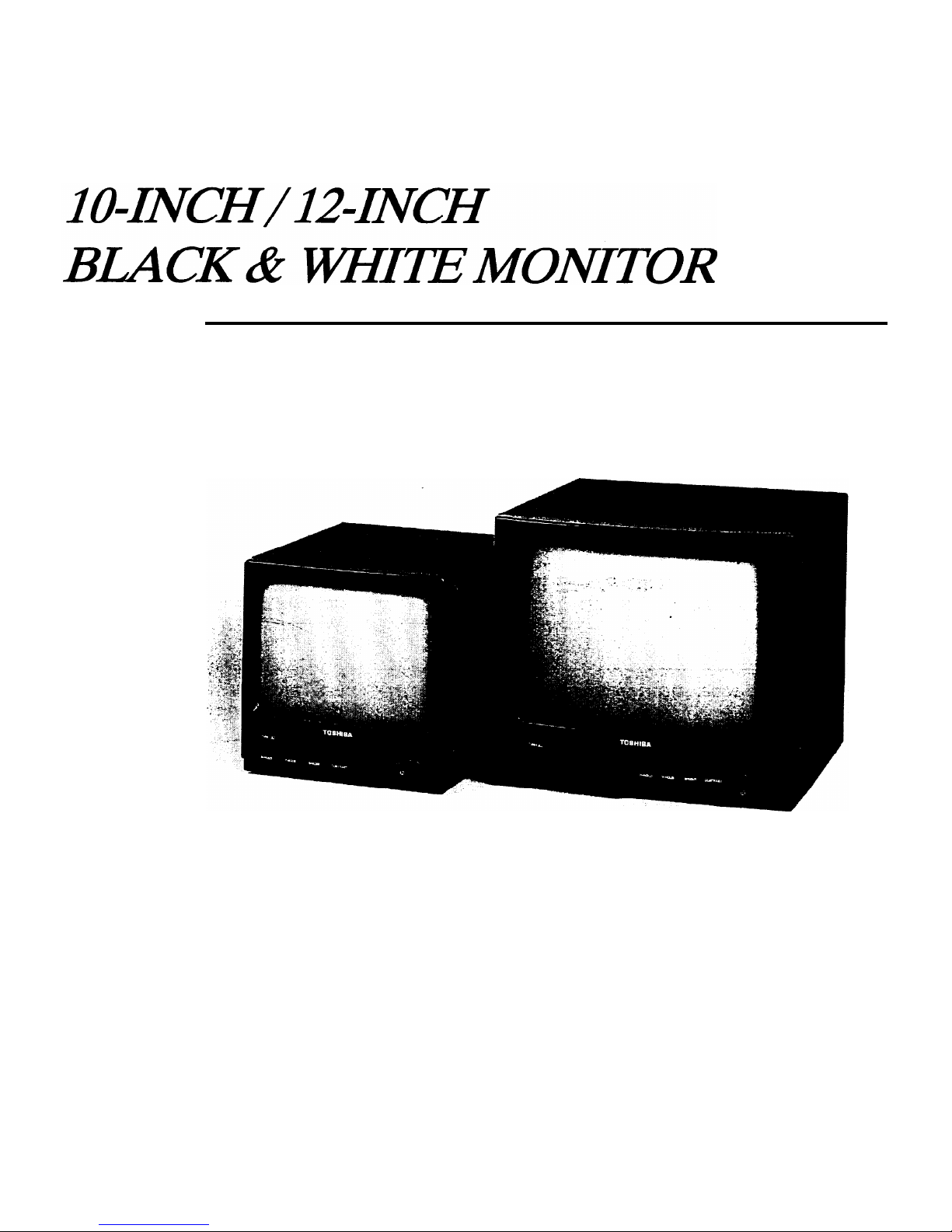
FRONT IO”
12”
1.
2.
3.
4.
5.
1
’ I I
;4
2
‘;3
H-HOLD (horizontal hold) CONTROL
When the picture .has slanting horizontal bars, rotate the H-HOLD control in either direction until
a stationary picture is obtained.
V-HOLD (vertical hold) CONTROL
When the picture rolls up or down on the screen, adjust V-HOLD control until there is a single
steady picture.
BRIGHT (brightness) CONTROL
Turn clockwise for more brightness and counterclockwise for less.
CONTRAST CONTROL
Turn clockwise to increase picture contrast and counterclockwise to decrease it.
POWER SWITCH
To turn the monitor power on, press once. To turn the power off, press once again.
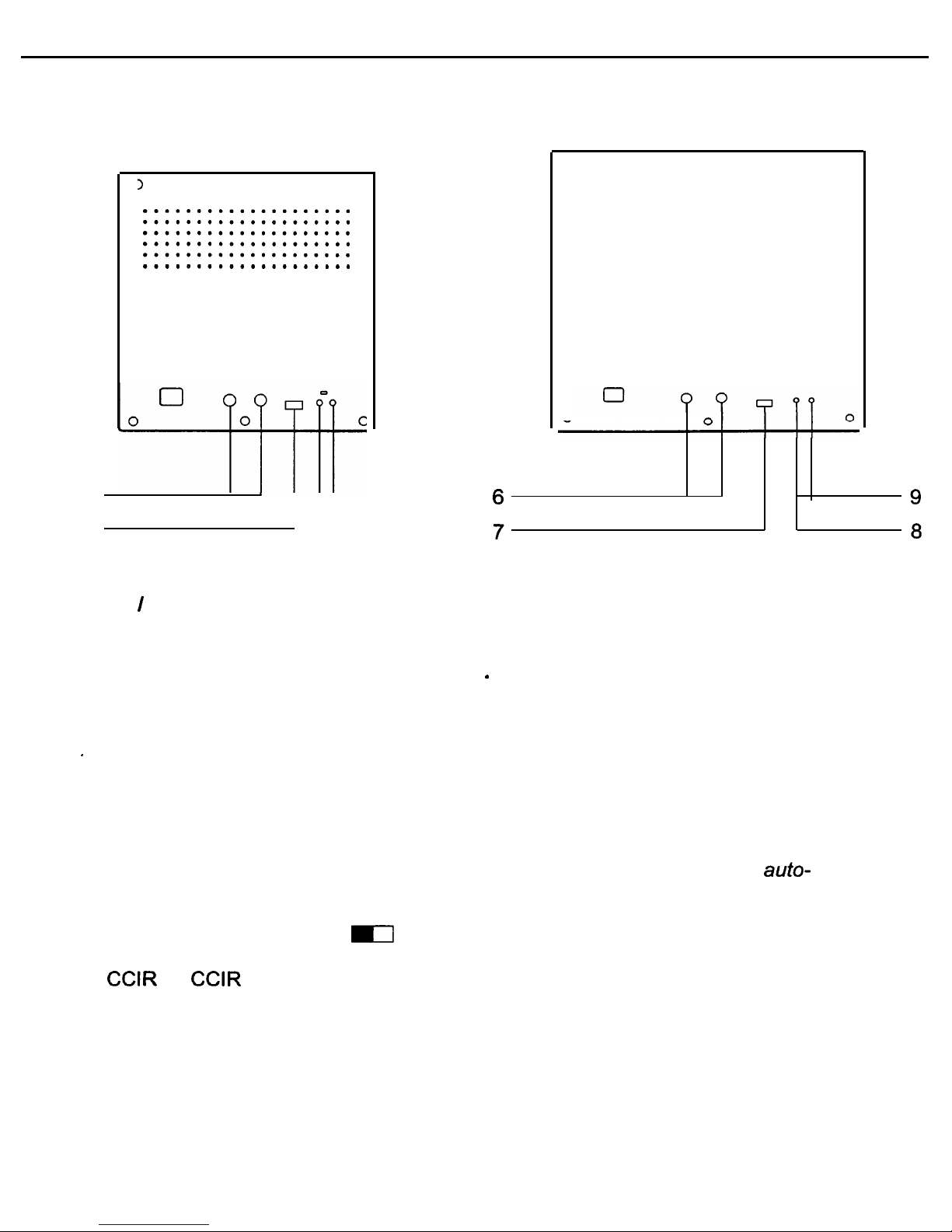
BACK IO”
12”
6.
7.
8.
9.
1
0
....................
....................
....................
....................
....................
....................
6
’
II
-9
7
‘-8
0
0
....................
....................
....................
....................
....................
....................
3
0
0
VIDEO IN / OUT CONNECTOR
Connector to the video output of a VCR or another monitor (for loop-through
connection) or to a video camera.
Loop-through output of the VIDEO IN connector . Connector the video input of
another monitor or a VCR.
Note: The impedance is automatically set to 75 ohm by the input of a signal on the
’
input connector while operating in a single connection mode. However, if a cable
is connected to the output connector, the connection is placed into the open
status by the multiple connection and high impedance automatically selected.
Caution: Do not leave an unused cable connected to the monitor. If a single cable is
used, then it must be connected to the input connector for the 75 ohm auto-
termination selector to function properly
SCAN MODE SELECTOR (EIA
m
CCIR)
Set to EIA
for
EIA standard.
Set to CCIR for CCIR standard.
V-HEIGHT CONTROL
To adjust this control for the vertical size of the picture.
V-LIN. CONTROL
To adjust this control for the vertical linearity of the picture.
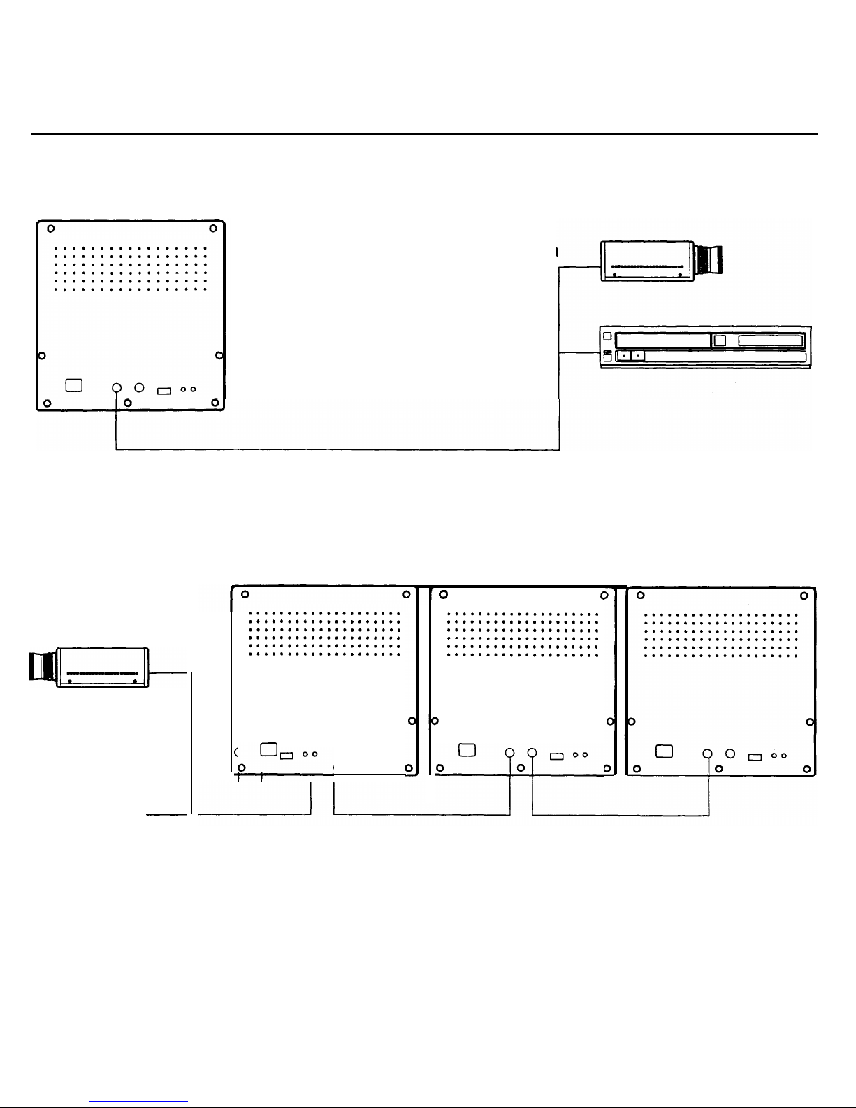
CONNECTION
SINGLE CONNECTION
MULTIPLE CONNECTION
to video camera
qzl_
to video output
-
....................
....................
....................
....................
....................
....................
3
p?“““,
o”
to video
camera
to video output
0
(1
....................
....................
....................
....................
....................
....................
)
+
Up to 3 monitor can be connected using the loop-through feature of this unit.
When this monitor is connected to additional monitors, the same picture can be obtained on all the
connected monitors.

SPECIFICATIONS
PICTURE TUBE(Useful screen size)
POWER SOURCE
POWER CONSUMPTION
SYSTEM
RESOLUTION
INPUT SIGNAL
SCANNING FREQUENCY
:
HORIZONTAL
: VERTICAL
LINEARITY
: HORIZONTAL
: VERTICAL
ACTIVE DISPLAY AREA
:
HORIZONTAL
: VERTICAL.
INPUT CONNECTOR(CAMERA)
CONTROL
:
FRONT
: BACK
OPERATING TEMPERATURE
AMBIENT HUMIDITY
DIMENSIONS(W x D x H)
WEIGHT
IO” Diagonal,
90”
Deflection Angle ( 8.7”)
12” Diagonal,
90”
Deflection Angle (11.6”)
EIA : AC 90 to 132V 50Hz/60Hz
CCIR : AC 198 to 254V 50Hz/60Hz
18 Watts
EIA or CCIR standard
more than 800 TV lines (center)
1
.OVp-p
(75 ohm)
EIA : 60Hz : 15.734KHz
CCIR : 50Hz : 15.625KHz
EIA : 59.94Hz
CCIR : 50Hz
10% MAX.
10% MAX.
10% overscanning
13% overscanning
BNC connector
H-HOLD, V-HOLD, BRIGHT, CONTRAST,
POWER SIW
V-LINEARITY, V-HEIGHT,
EIAICCIR SELECTOR S/W
0°C - 40°C (32°F - 104°F)
0% - 90%
IO” : 220mm x 248mm x 234mm
12” : 305mm x 302mm x 287mm
IO” : 4.3Kg
12” : 7.3Kg
 Loading...