

Page 1
SERVICE MANUAL
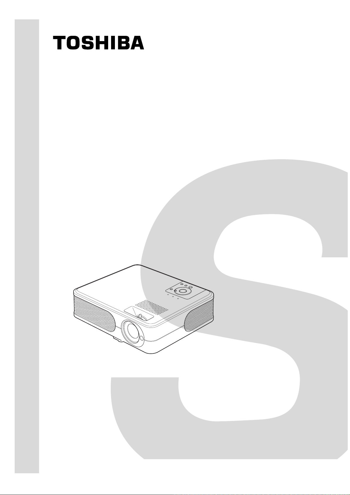
3LCD DATA PROJECTOR
TLP-X2000E/B/U/C
TLP-X2500E/B/U/C
FILE NO. 330-200711GR
Rev.03
TLP-X3000E/B/U/C
The above models are classified as green product (s) (*1), as indicated by the underlined serial number (s).
This Service Manual describes replacement parts for green product (s). When repairing any green product (s), use
the parts described in this manual and lead-free solder (*2).
For (*1) and (*2) , see the next page.
Published in Japan, May 2008 GREEN© TOSHIBA CORPORATION
Page 2
I
Page 3
C
ontents
Table of Contents
Chapter 1 1-1
Specifications 1-1
Using the Menus 1-3
Names of the Terminals on the Rear Panel 1-4
Name of each part on document camera 1-5
List of Supported Signals 1-6
Chapter 2 2-1
Replaceable Part Hierarchy 2-1
Required Tools 2-2
Parts Replacement 2-3
Replacement of optical parts 2-15
Chapter 3
SINGOWS 2000 3-1
Chapter 4 4-1
Firmware Upgrade 4-1
Chapter 5 5-1
Wiring Diagram 5-1
Block Diagram 5-2
Chapter 6 6-1
LED Display 6-1
Troubleshooting 6-2
Operation of Power Supply 6-9
Chapter 7 7-1
Electrical adjustment 7- 1
Chapter 8 8-1
Functional Test 8-1
3-1
Chapter 9 9-1
Spare Parts List 9-1
II
Page 4
Chapter 1
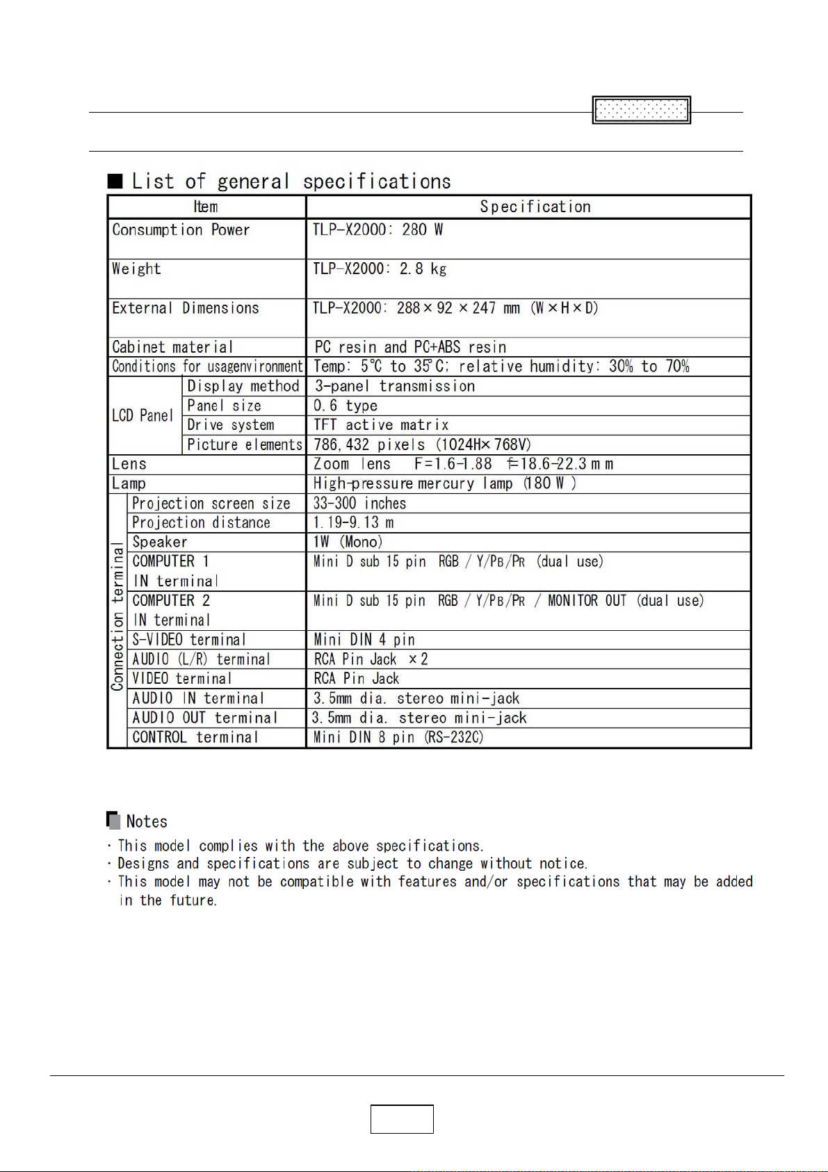
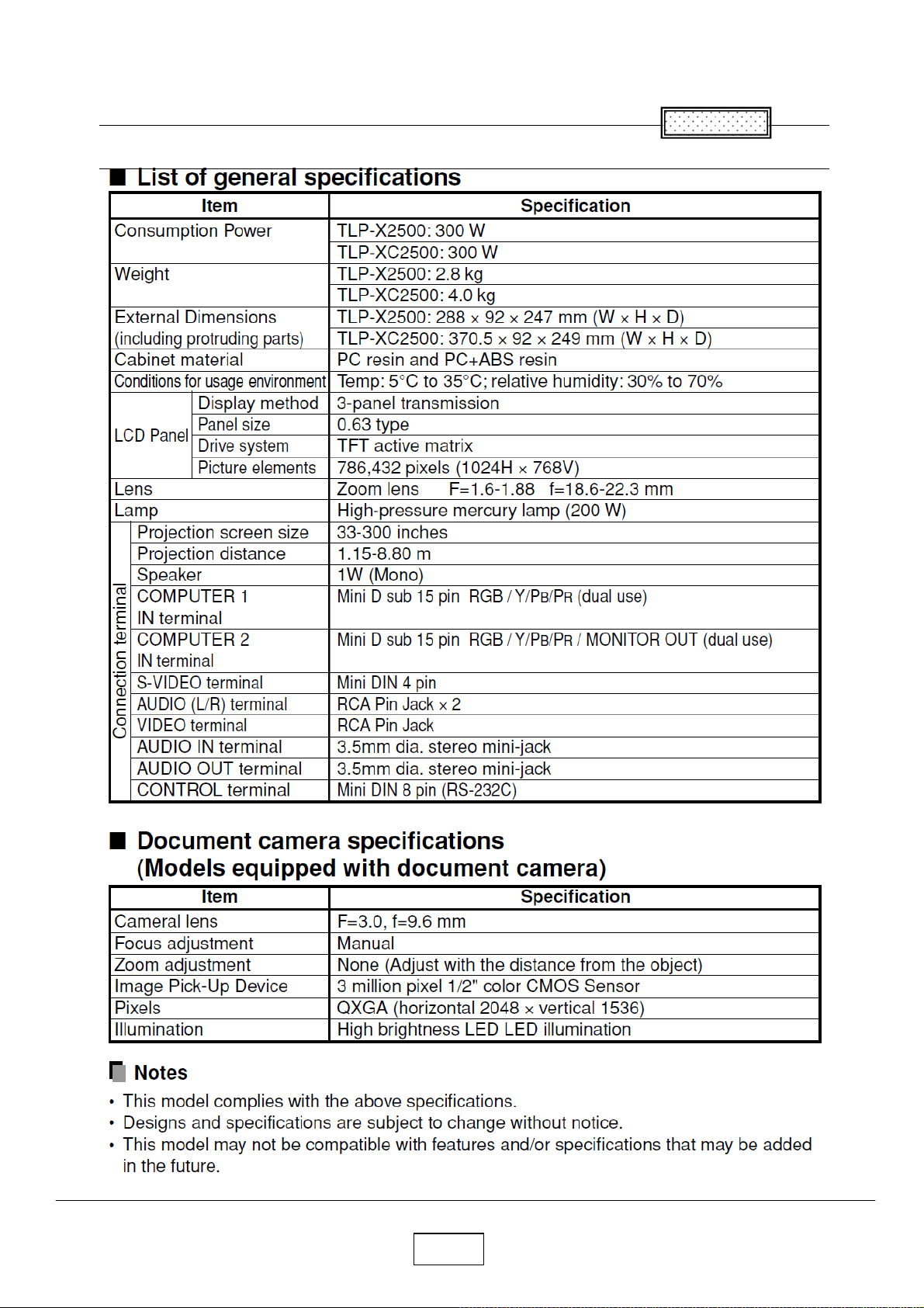
Specifications
Chapter 1
1-1a
Page 5
Chapter 1
Specifications
Chapter 1
1-1b
Page 6
Chapter 1
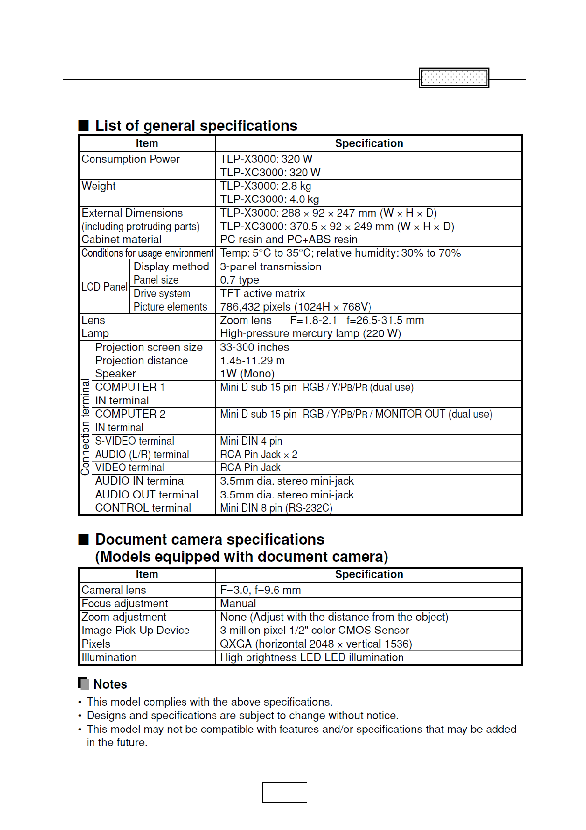
Specifications
Chapter 1
1-1c
Page 7
Chapter 1
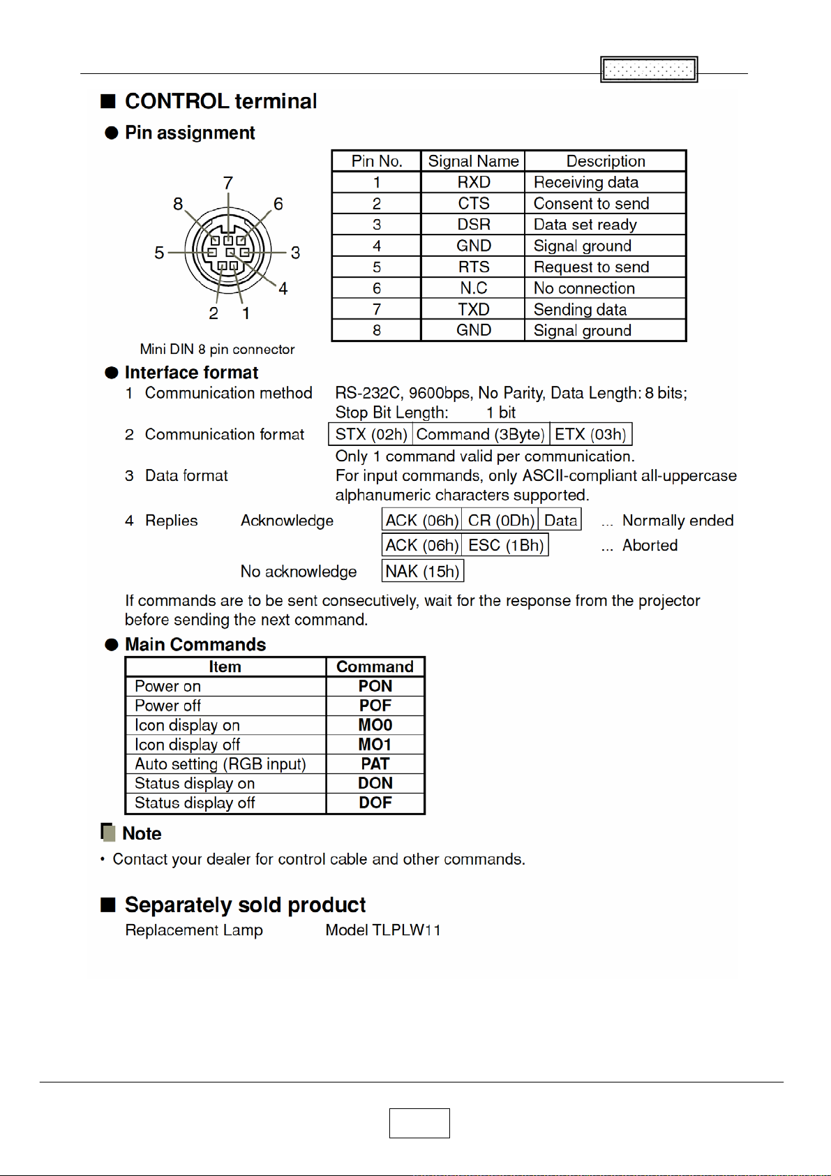
1-2
Page 8
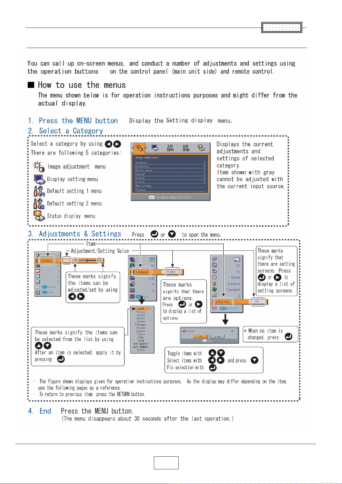
Using the Menus
Chapter 1
1-3
Page 9
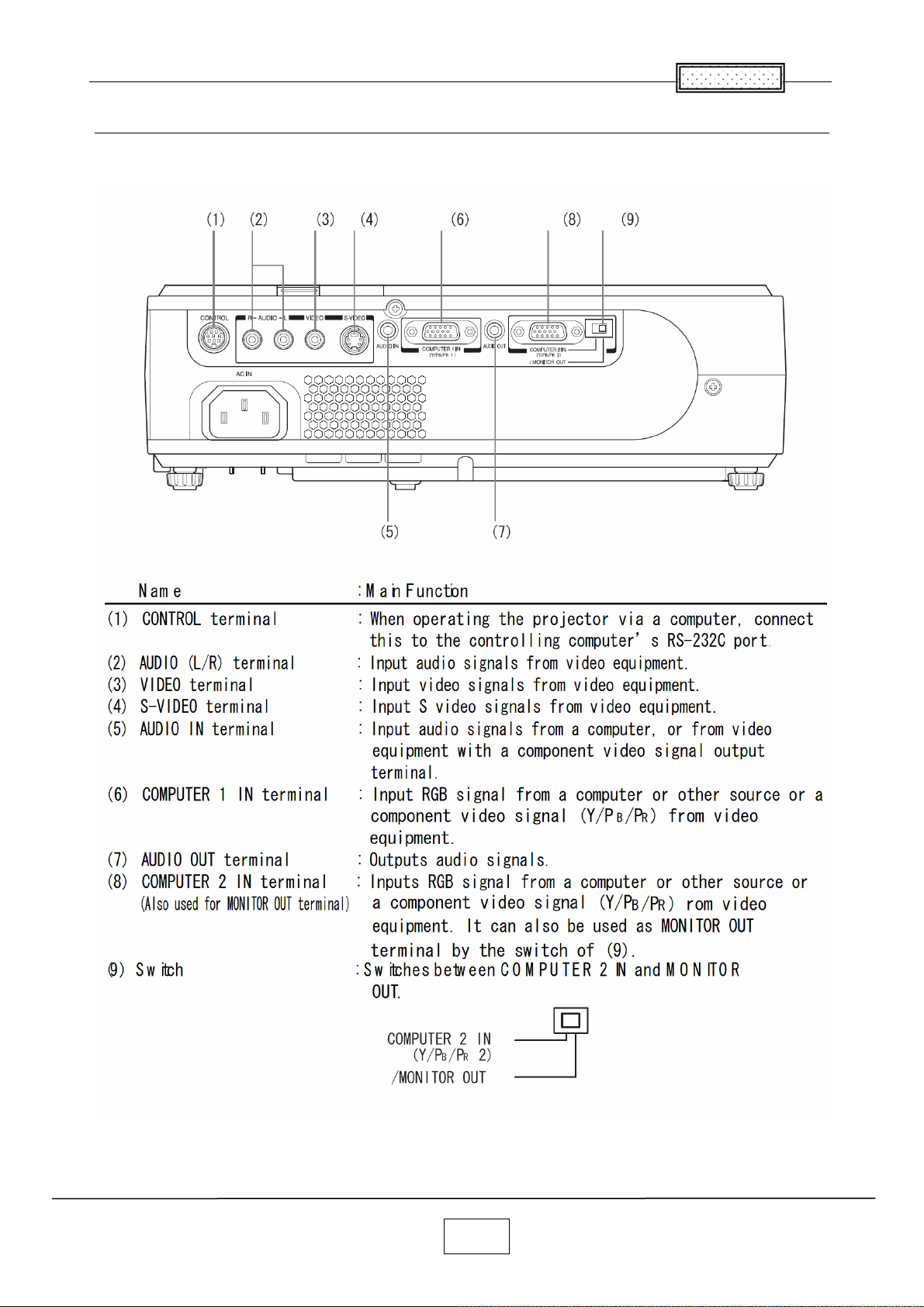
Chapter 1
Names of the Terminals on the Rear Panel
1-4
Page 10
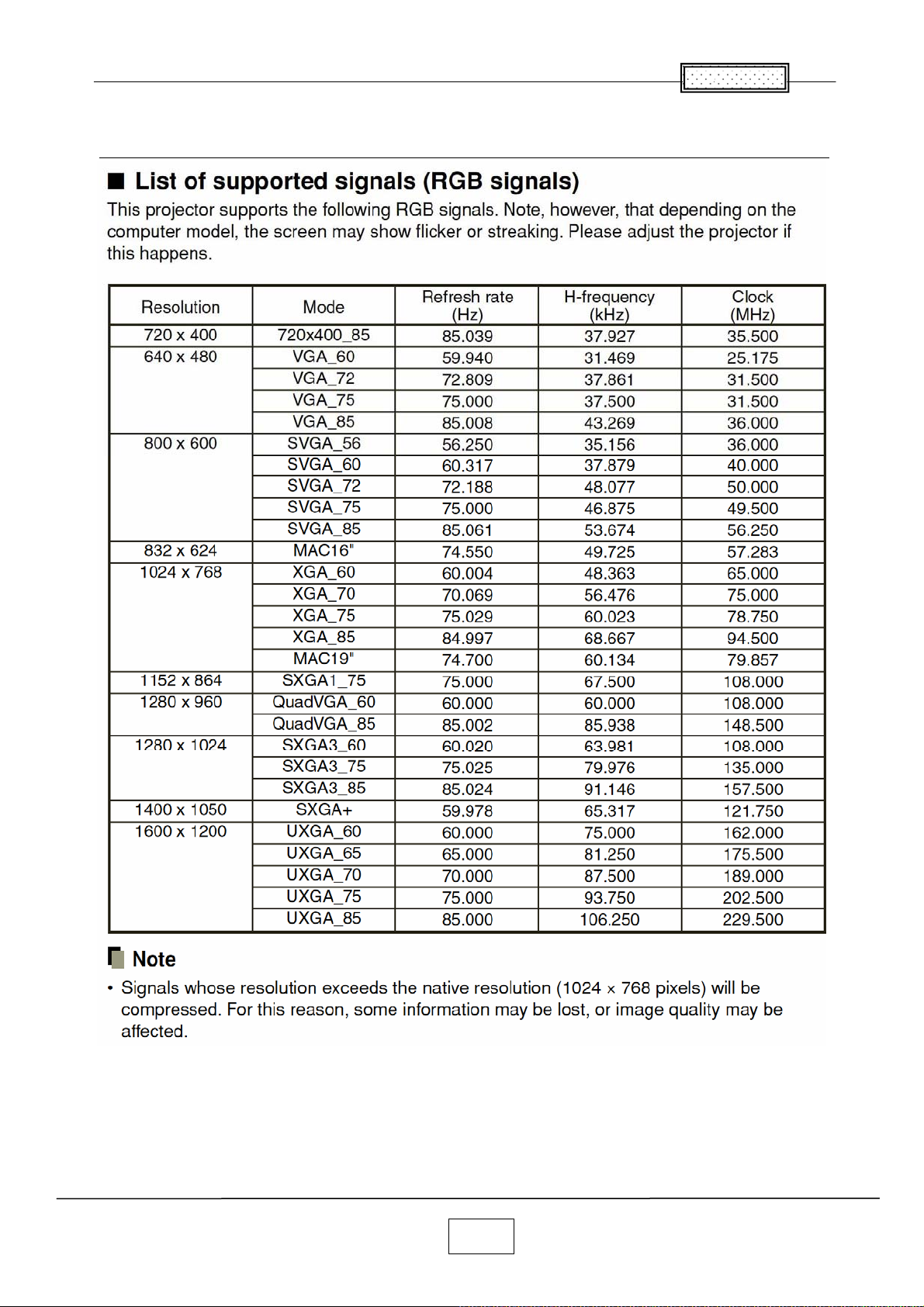
List of Supported Signals
Chapter 1
1-5
Page 11
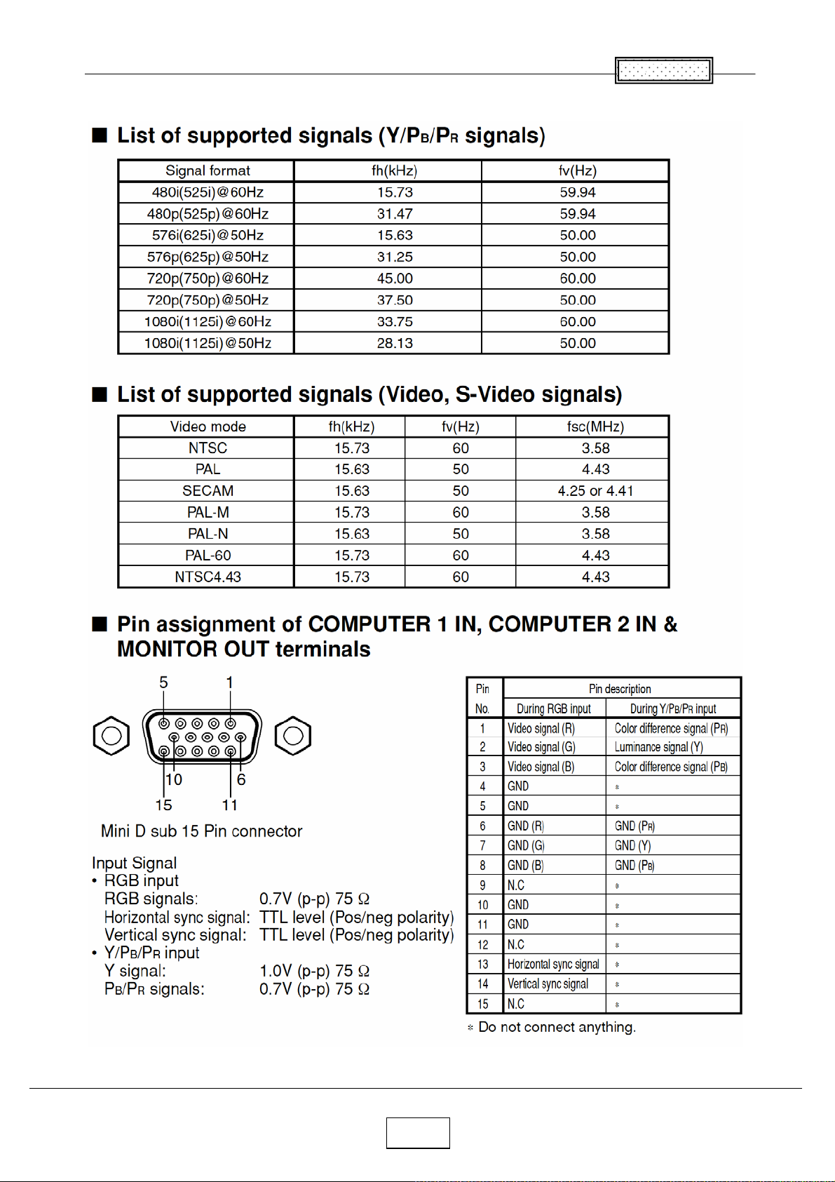
Chapter 1
1-6
Page 12
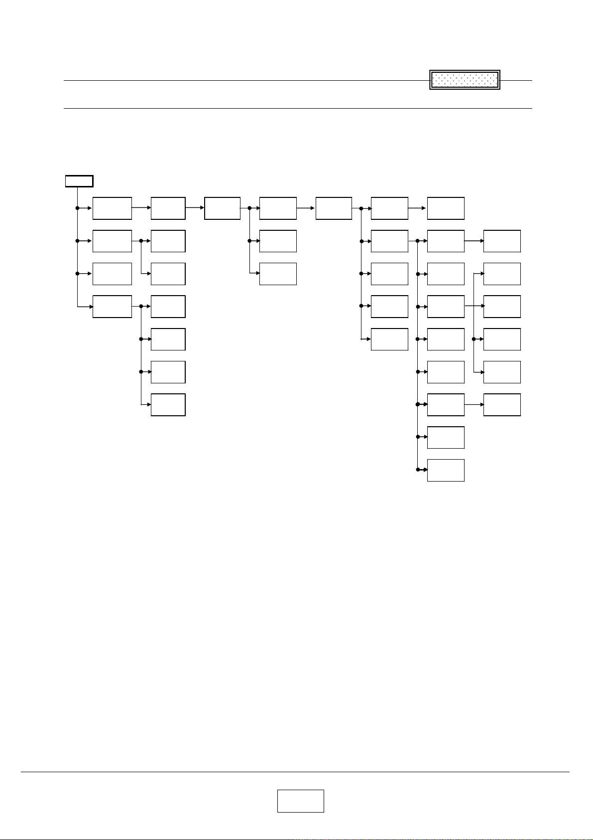
Chapter 2
2
Replaceable Part Hierarchy
Replaceable Part Hierarchy
The flow chart below shows what parts must be removed to access each replaceable part in the projector.
The parts on the first level (Ex.Lamp cover) are accessible without removing any other parts.
The move levels down that a part is, the more parts you need to remove in order to access it.
Start
Chapter
Lamp
cover
Control
panel
Lens cover
Camera
assy
Lamp
Bracket
LED
board
Speaker
Camera
Main
Camera
KEY
Camera
CMOS
Camera
LED
Top cover
PCB Main
Remocon
receiver
PCB
Sensor
Cover for
Power
Power
Main
Optical
Engine
Intake
Fan
Exhaust
Fan
Powe
Filter Fan
Front
panel
LCD Fan
Door SW
Balast &
FAN assy
Lens
Color
wheel
Power
Filter
LCD
Panel
LCD Filter
Foot ADJ
PBS Fan
Balast
Fan
Lamp
Driver
Rear
panel
Thermal
SW
2-1
Page 13
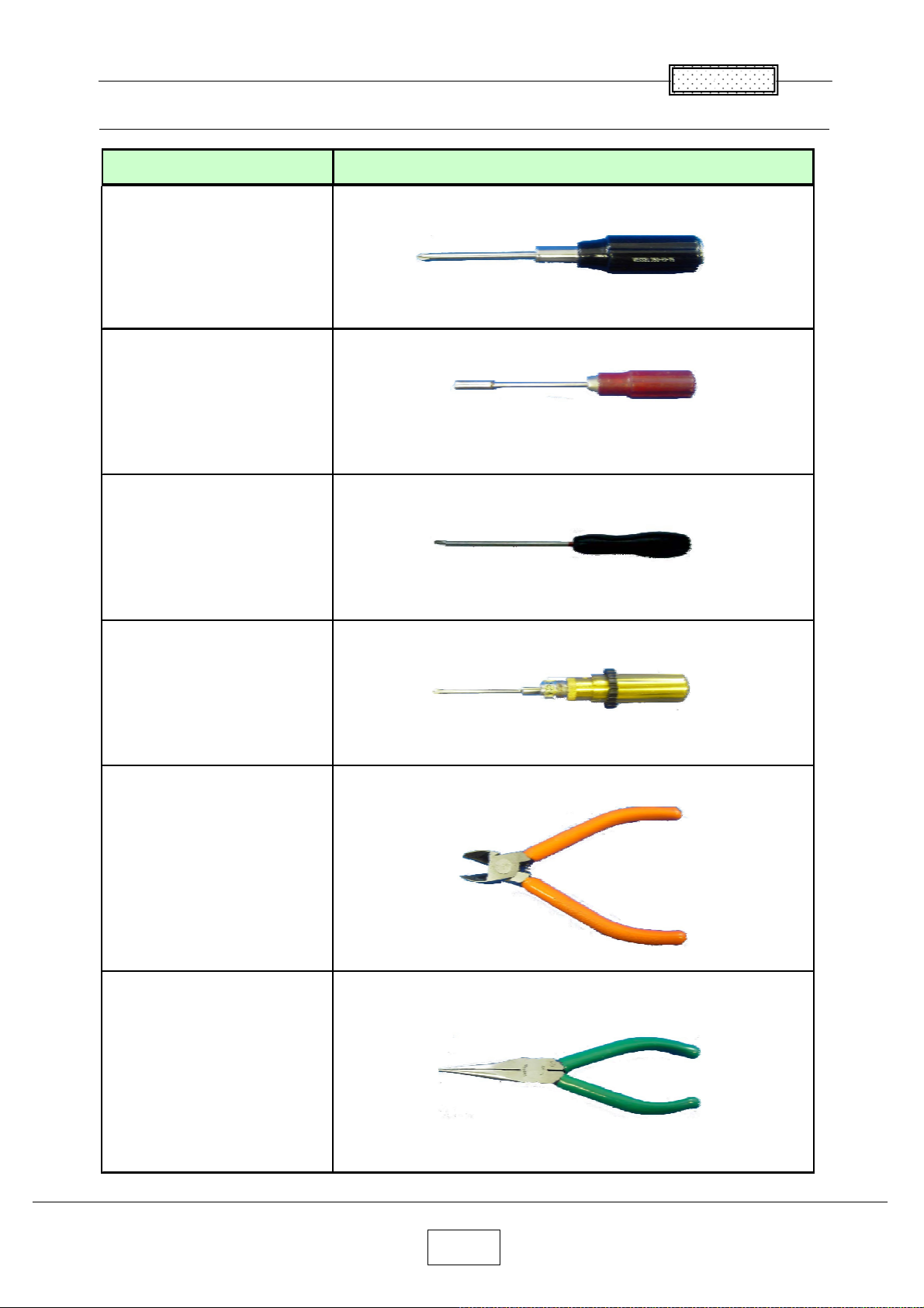
Required Tools
䠇
䠇
Item Photo
Driver bit (䠇) No 2
Box driver M3
Chapter 2
Driver bit (
Torque driver bit (
Nippers
) No 0
) No 2
Cutting pliers
2-2
Page 14
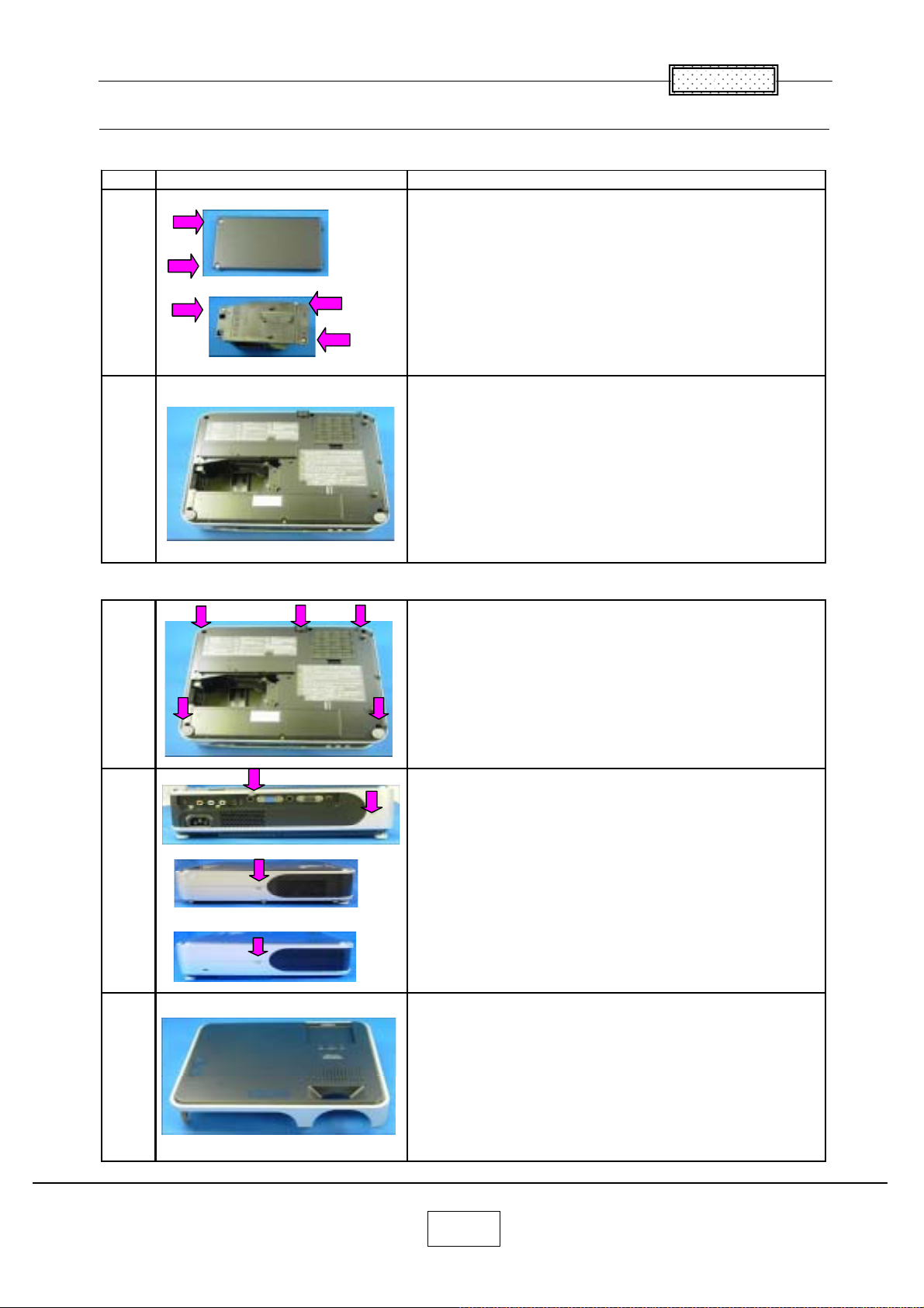
Parts Replacement
g
g
1.Lamp
No Fi
1
ure Explanation
Chapter 2
Remove two lamp cover screws.
Remove three lamp screws.
2
2.Top Cover
Lamp is pulled out.
Remove five screws at the bottom.
Remove two screws at the rear.
Remove a screw at the ri
ht.
Remove a screw at the left.
Top cover is removed.
3
2-3
Page 15
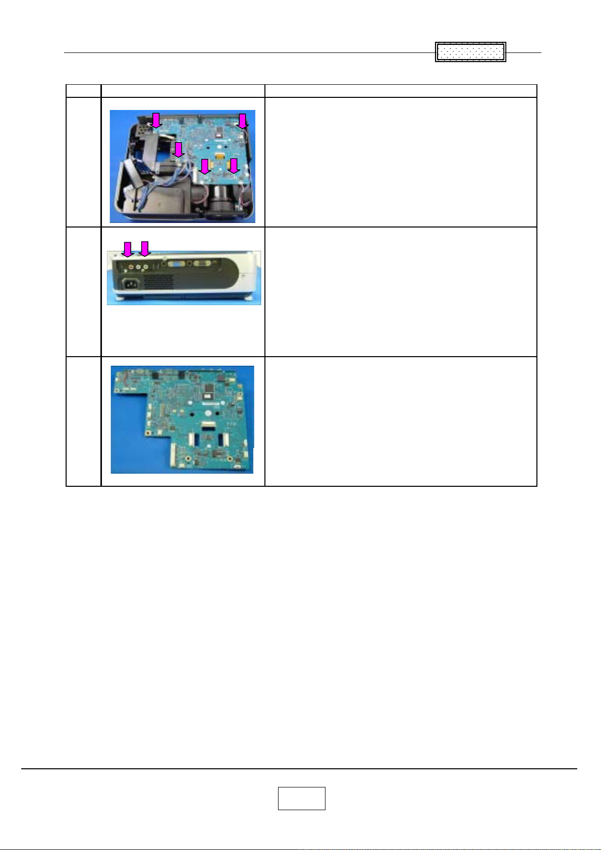
3.Main Board
Step Figure Explanation
All the connectors on a main board unit are removed.
Chapter 2
1
2
3
Remove five screws.
Remove two screws at the rear cover.
Main board is removed.
2-4
Page 16
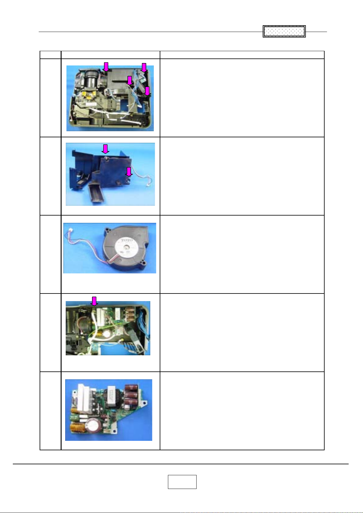
4.Main Power Unit
Step Figure Explanation
Remove four screws.
1
Cover & Power Intake FAN are removed.
Chapter 2
2
3
4
Remove two screws.
Power Intake FAN are removed.
Remove a screw.
5
Main Power Unit is taken out.
2-5
Page 17
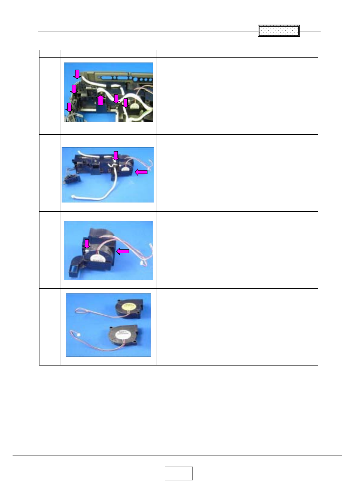
5.PBS & Ballast FANs
Step Figure Explanation
Remove six screws.
1
Balast & FAN assy is taken out.
Chapter 2
2
3
4
Remove two screws.
Remove two screws.
Ballast FANs are removed.
PBS FANs are removed.
2-6
Page 18
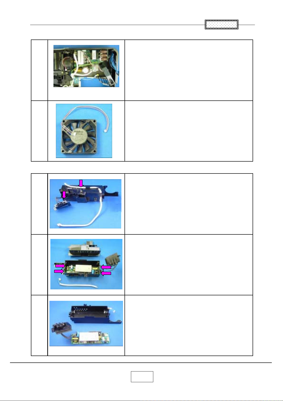
6.Exhaust Fan
Chapter 2
Remove no screw.
1
2
7.Ballast
1
Note.
May be very tight.
Exhaust Fan is removed.
Remove two screws.
2
3
Cover is removed.
Pinch a stud with cutting pliers. (4 points)
Then pull up PC Board.
Ballast is removed.
2-7
Page 19
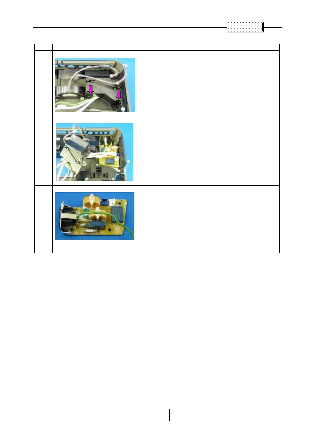
8.Filter Power
Step Figure Explanation
Remove two screws.
1
Cover is removed.
2
Chapter 2
3
Filter Power is taken out.
2-8
Page 20
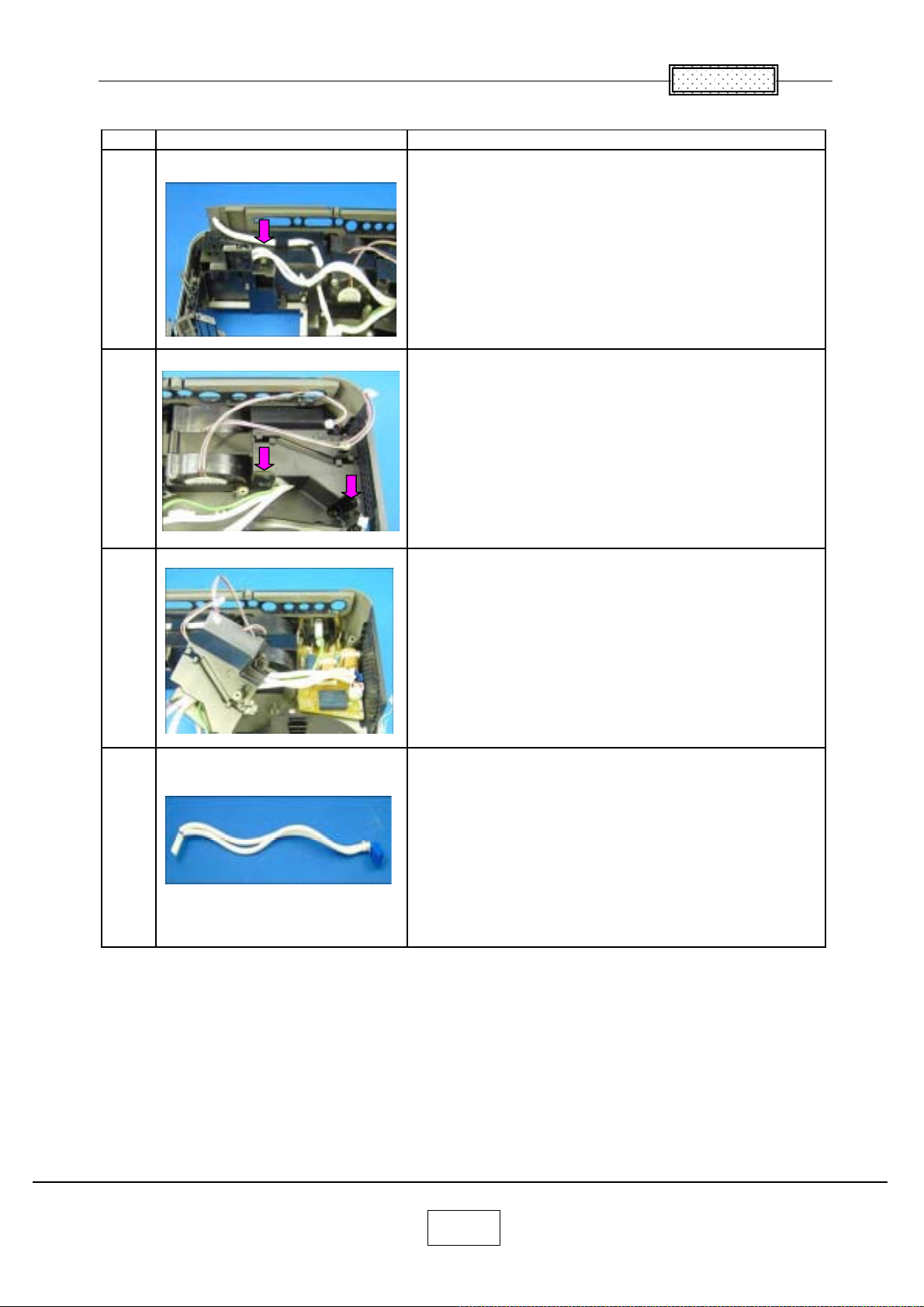
9.Thermal Switch
Step Figure Explanation
Remove a screws.
1
Remove two screws.
2
Chapter 2
3
4
Cover is removed.
Thermal Switch is removed.
2-9
Page 21
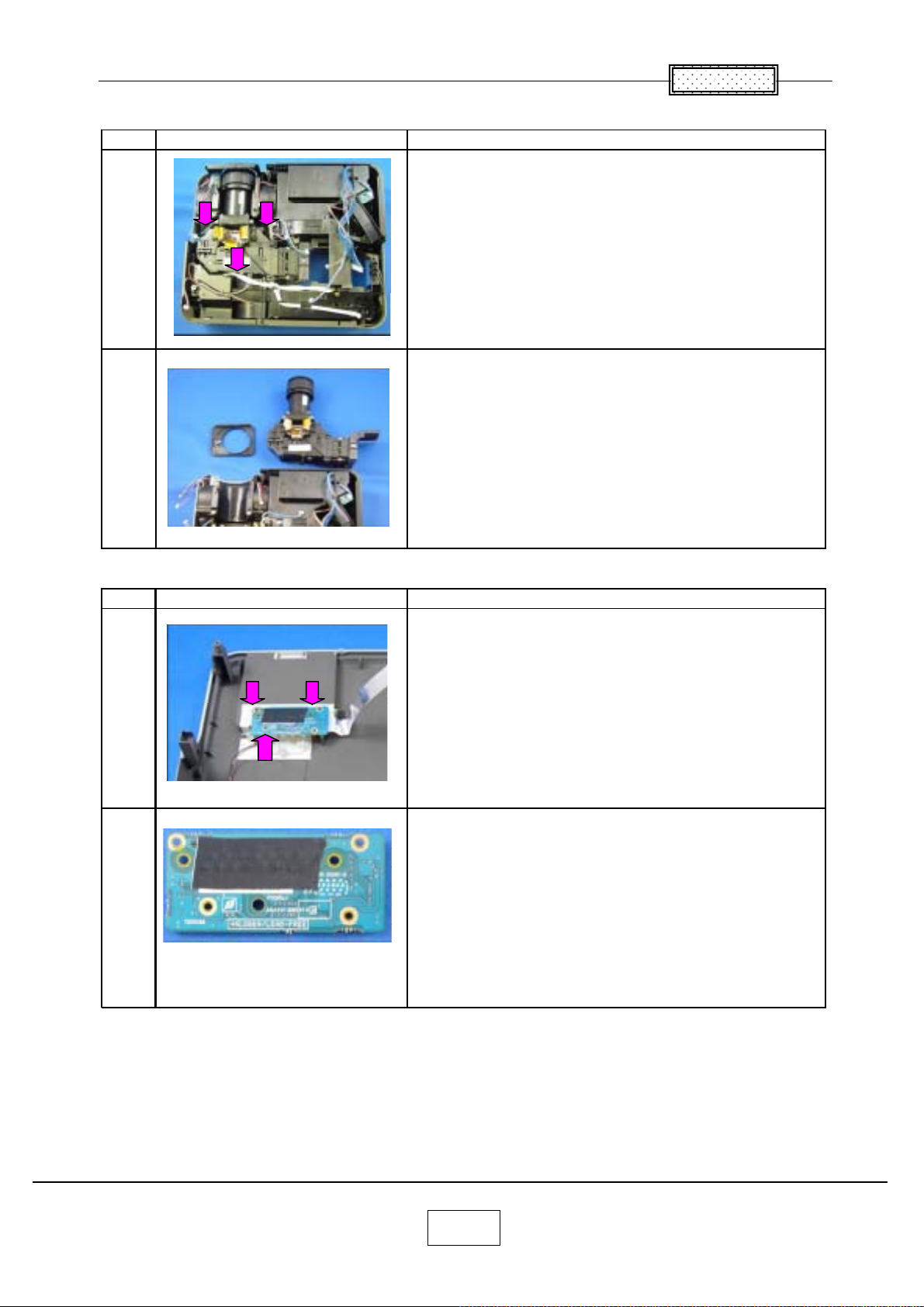
10.Optical Emgine
Step Figure Explanation
Remove three screws.
1
Optical Engine is taken out.
2
Chapter 2
11.Relay Board
Step Figure Explanation
Remove three screws.
1
Relay Board is removed.
2
2-10
Page 22
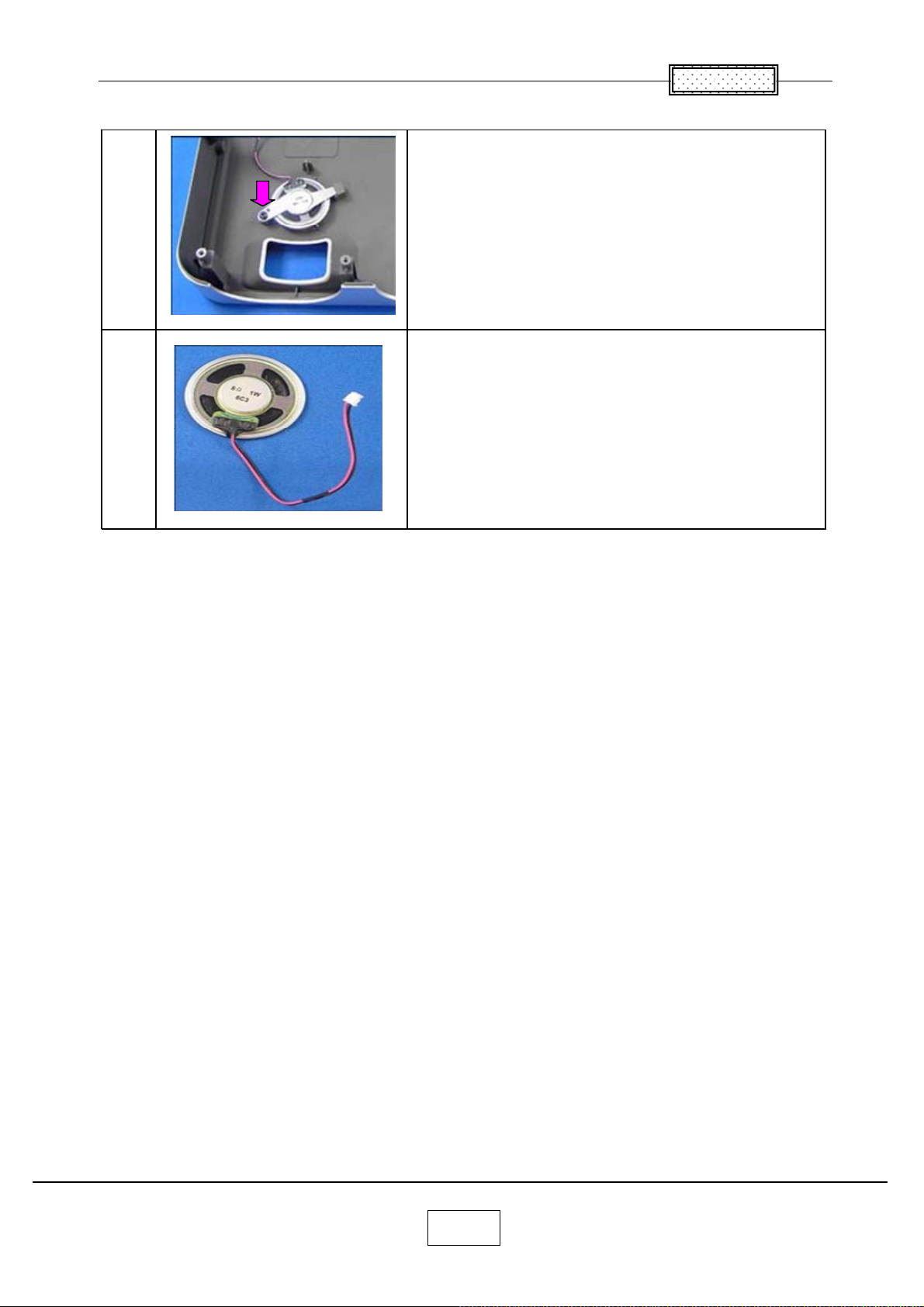
15.Speaker
1
2
Chapter 2
Remove a screws.
Speaker is removed.
2-11
Page 23
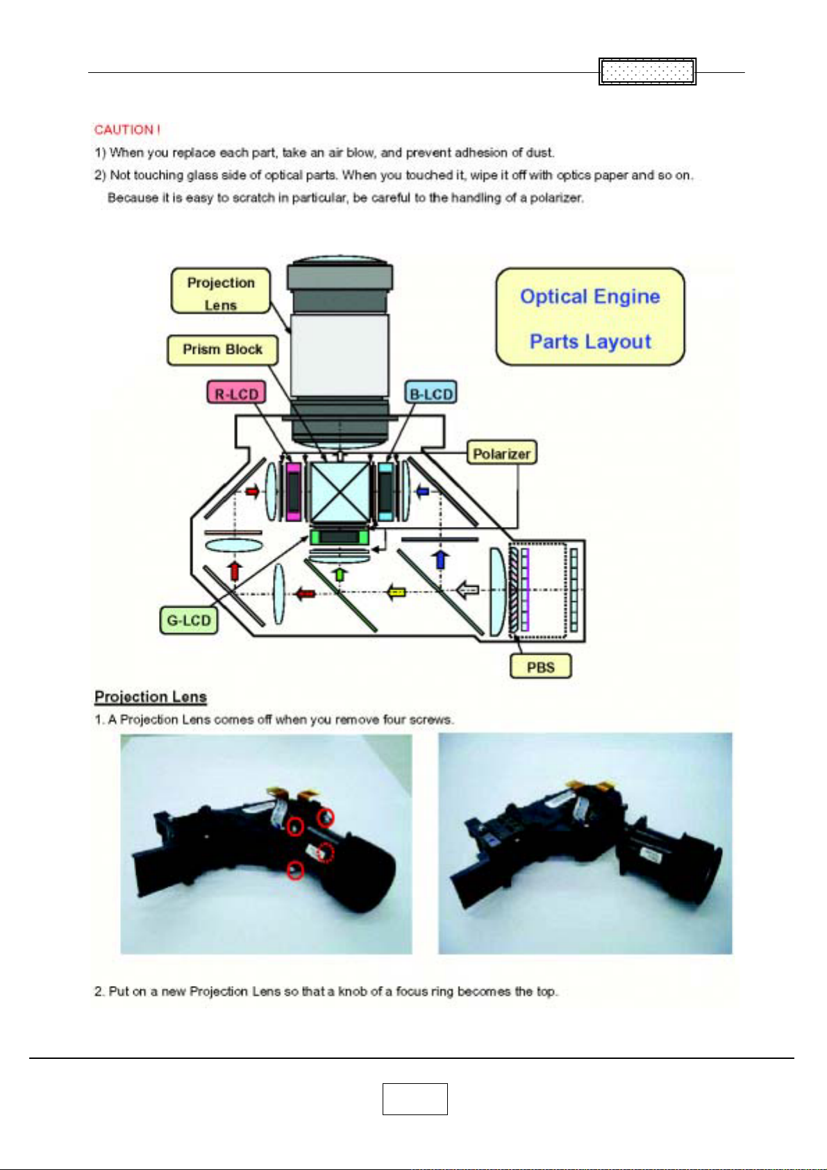
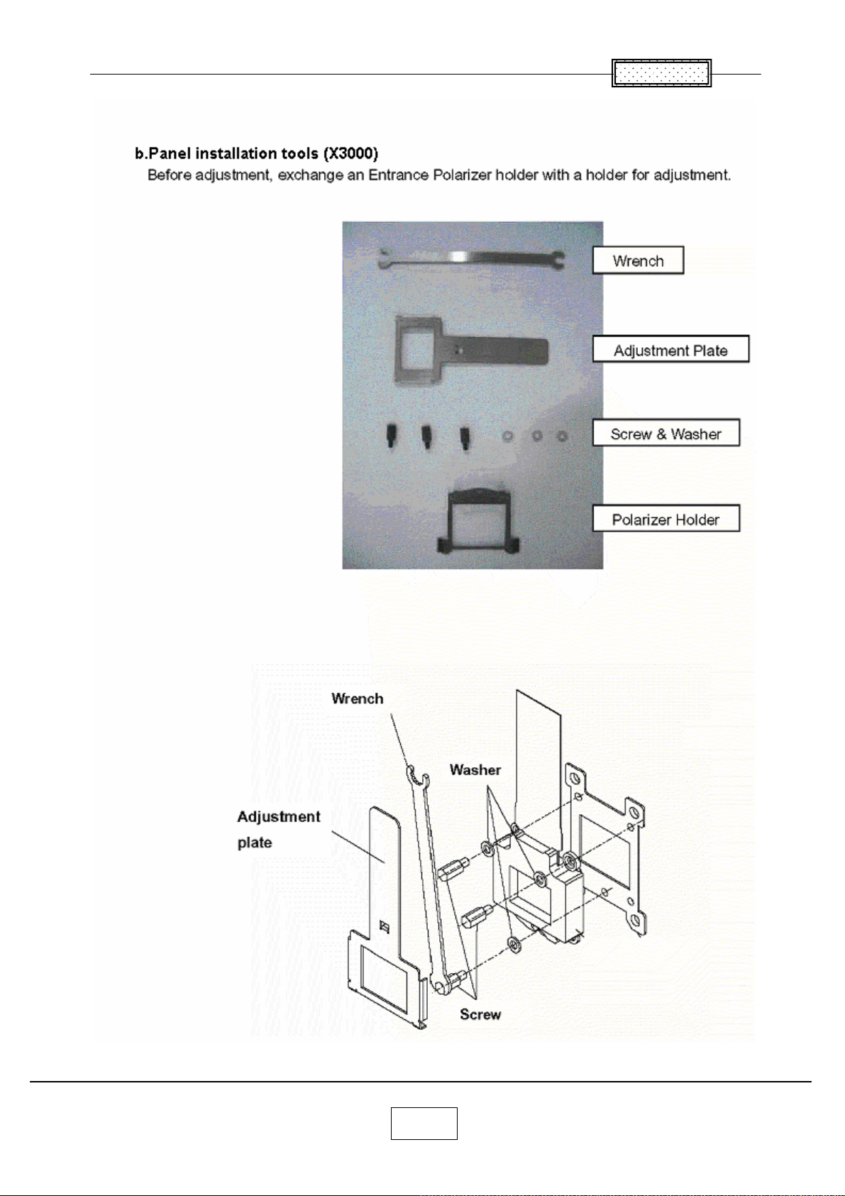
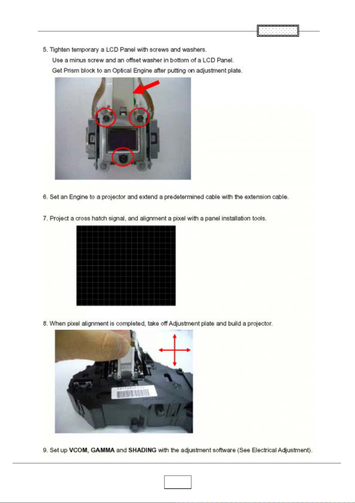
Replacement of Optical Parts
Chapter 2
2-12
Page 24
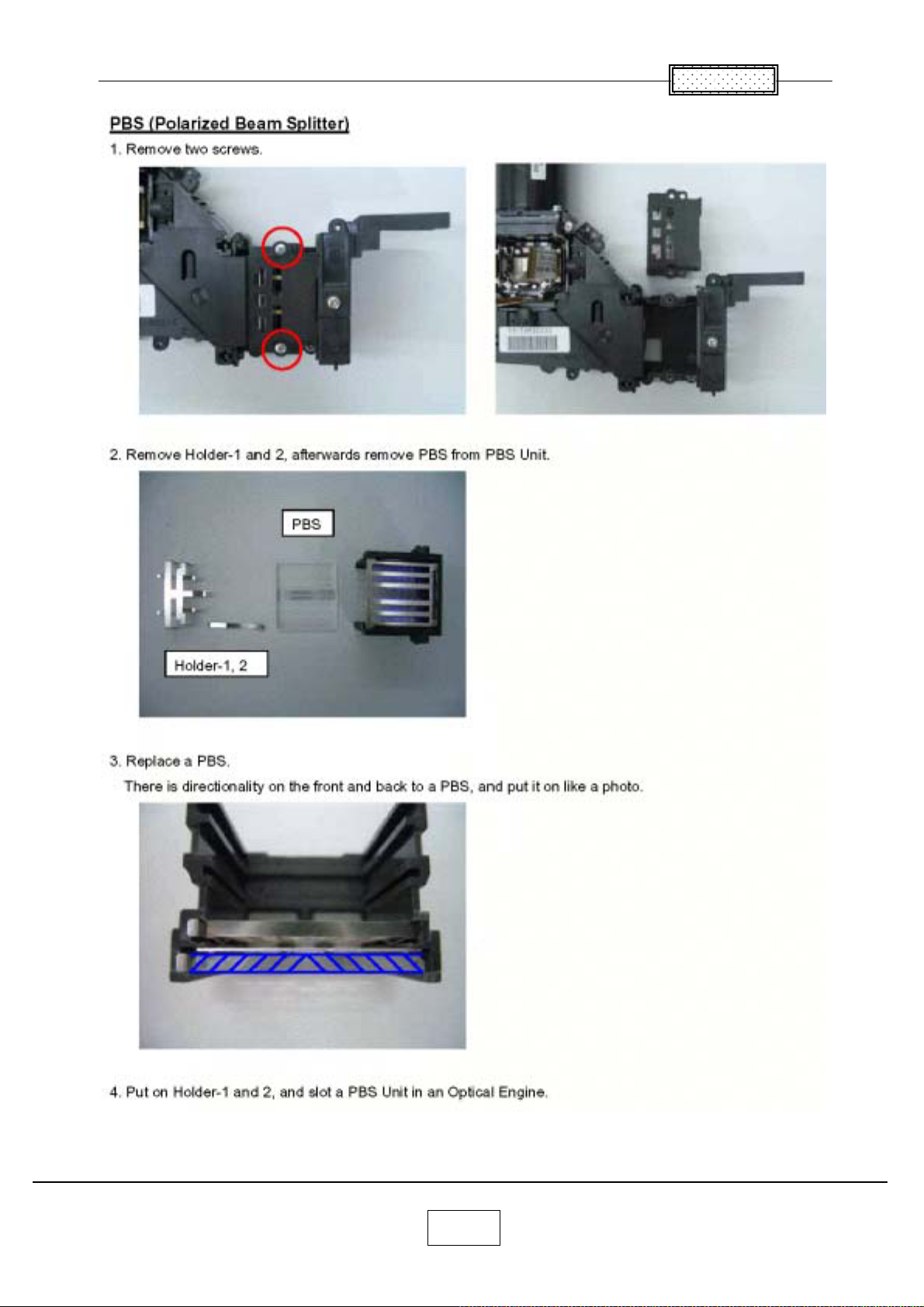
Chapter 2
2-13
Page 25
Chapter 2
2-14
Page 26
Chapter 2
2-15
Page 27
Chapter 2
2-16
Page 28
Chapter 2
2-17
Page 29
Chapter 2
2-18
Page 30
Chapter 2
2-19
Page 31
Chapter 3
SINGOWS 2000
Install the Software on the Computer
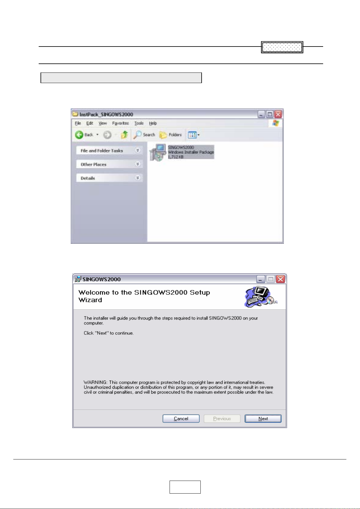
The software you download is bundled into one .MSI file.
Double-click the file to install the signal generating software.
Chapter 3
The Install Wizard appears,ready to begin the install process.
Click the next button.
3-1
Page 32
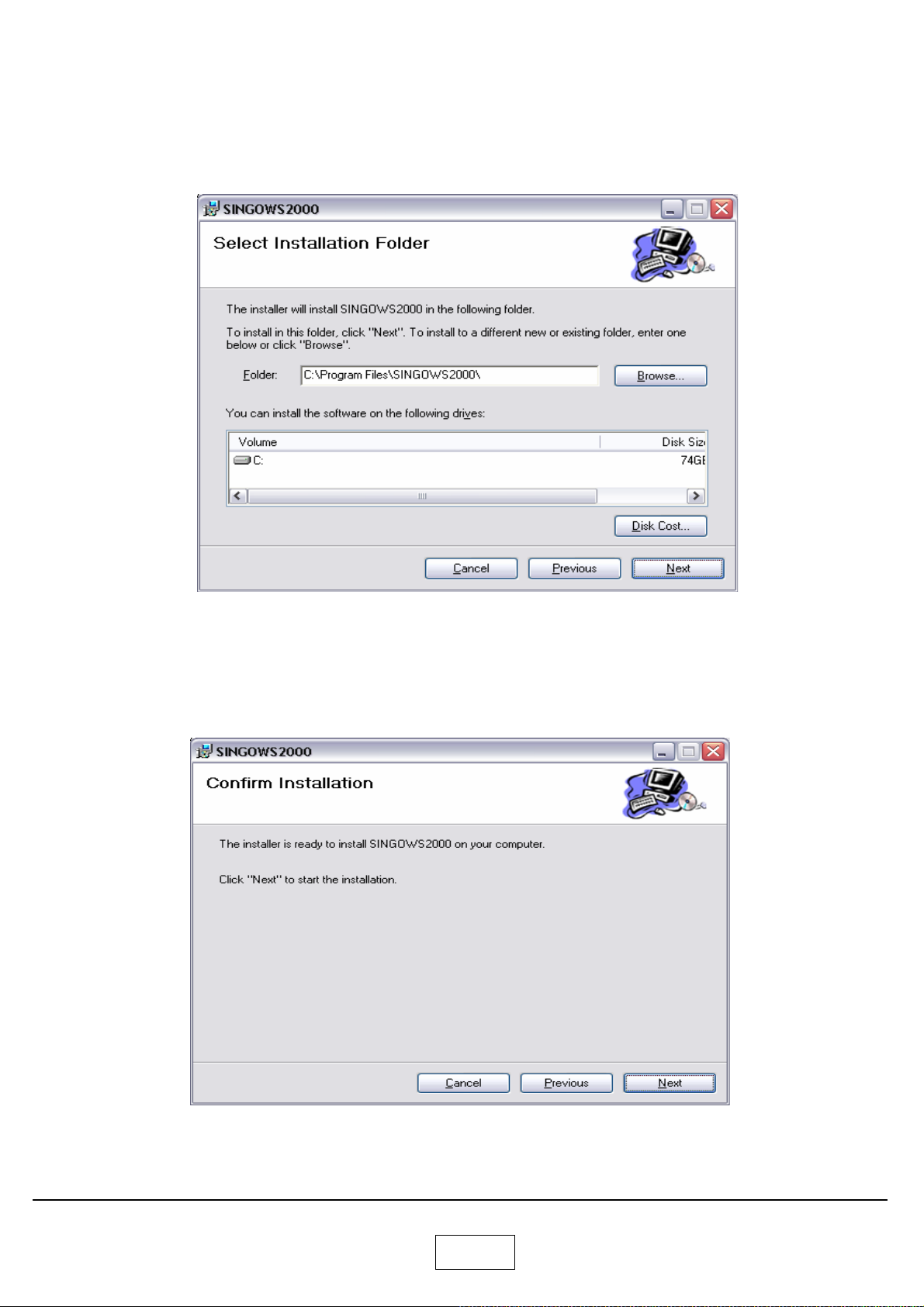
The Select Installation Folder dialog box appears.
Navigate to the location where you stored the software files.
Click the next button.
The confirm Installation dialog box appears.
Click the next button.
3-2
Page 33
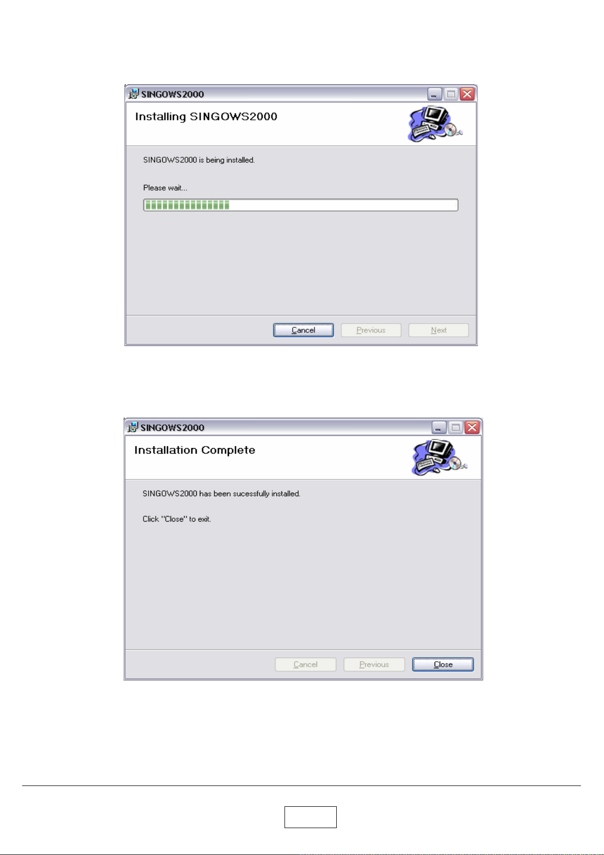
The Installing software dialog box appears.
The Installation Complete dialog box appears.
Click the close button.
3-3
Page 34
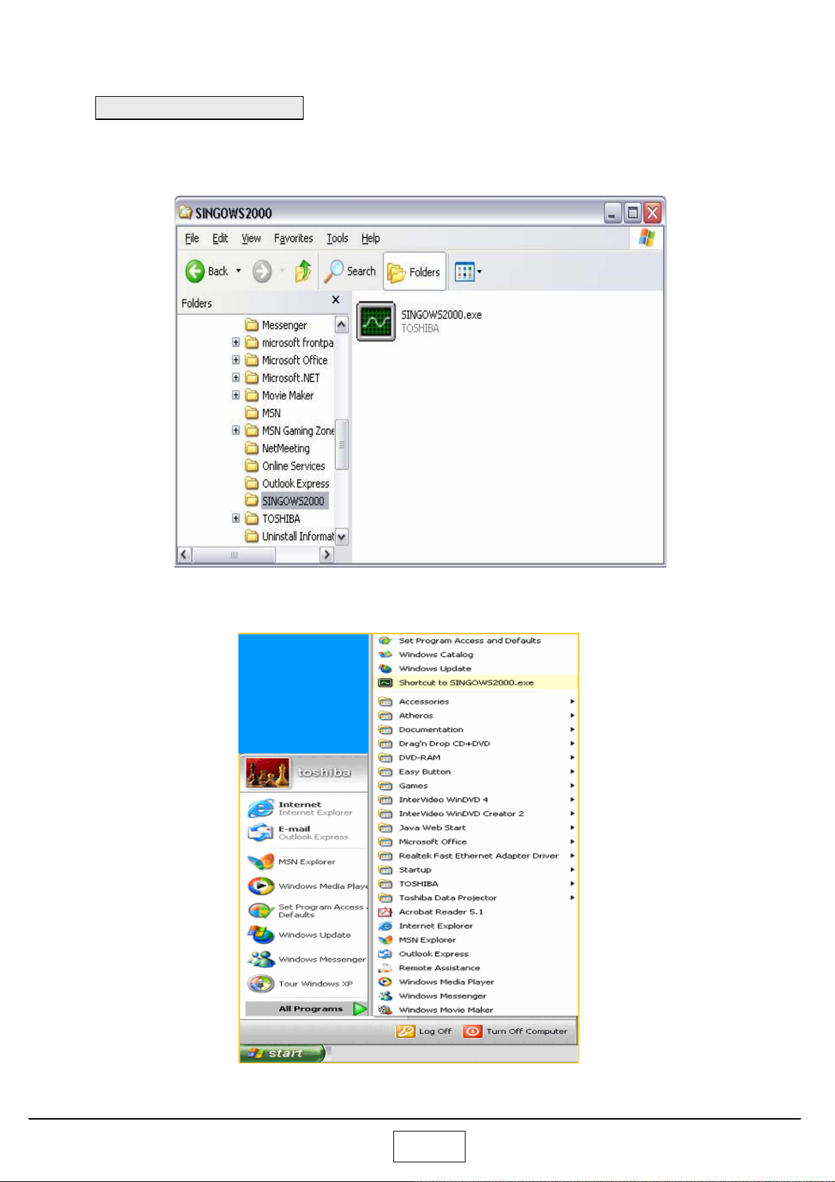
Startup the Software
Open Windows Exploler, navigate to the location where you stored the files, Then double click the
SINGOWS2000.EXE.
Moreover, even if it chooses the shortcut of the All programs of start, it can startup
.
3-4
Page 35
Chapter 4
Chapter 4
Firmware Upgrade
Upgrade the software
Connect the control cable to the control terminal on the projector.
Then plug the RS232C connector on the other end of the cable into a RS232C port on the computer.
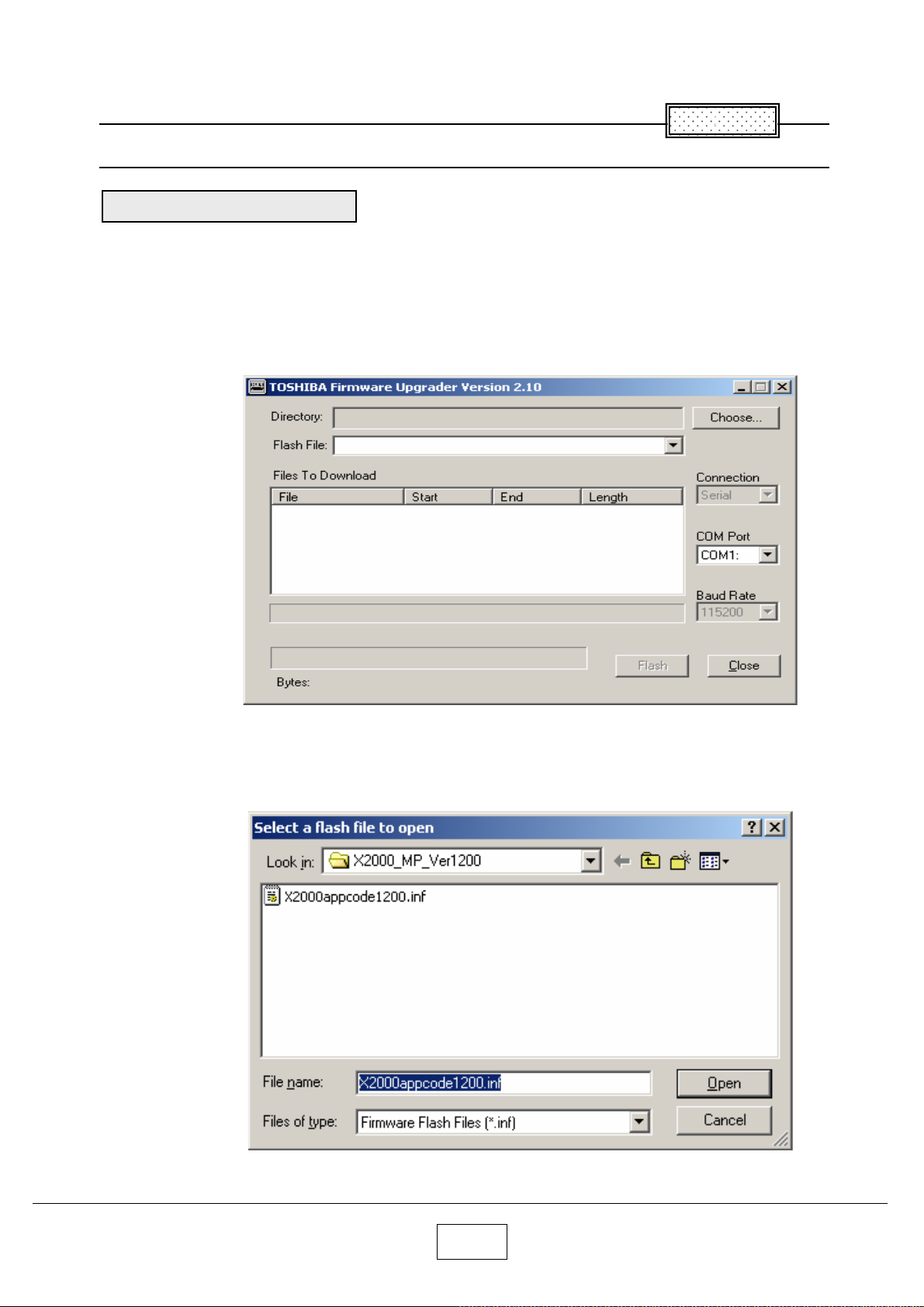
Open Windows Explorer navigate to the location where you stored the upgrade files, and then double click
the Firmware Upgrader.exe.
The Upgrade Wizard appears. Click the Choose button to open the Select File Dialog box.
In the Open File dialog box, select the .inf file, and then click Open button.
4-1
Page 36
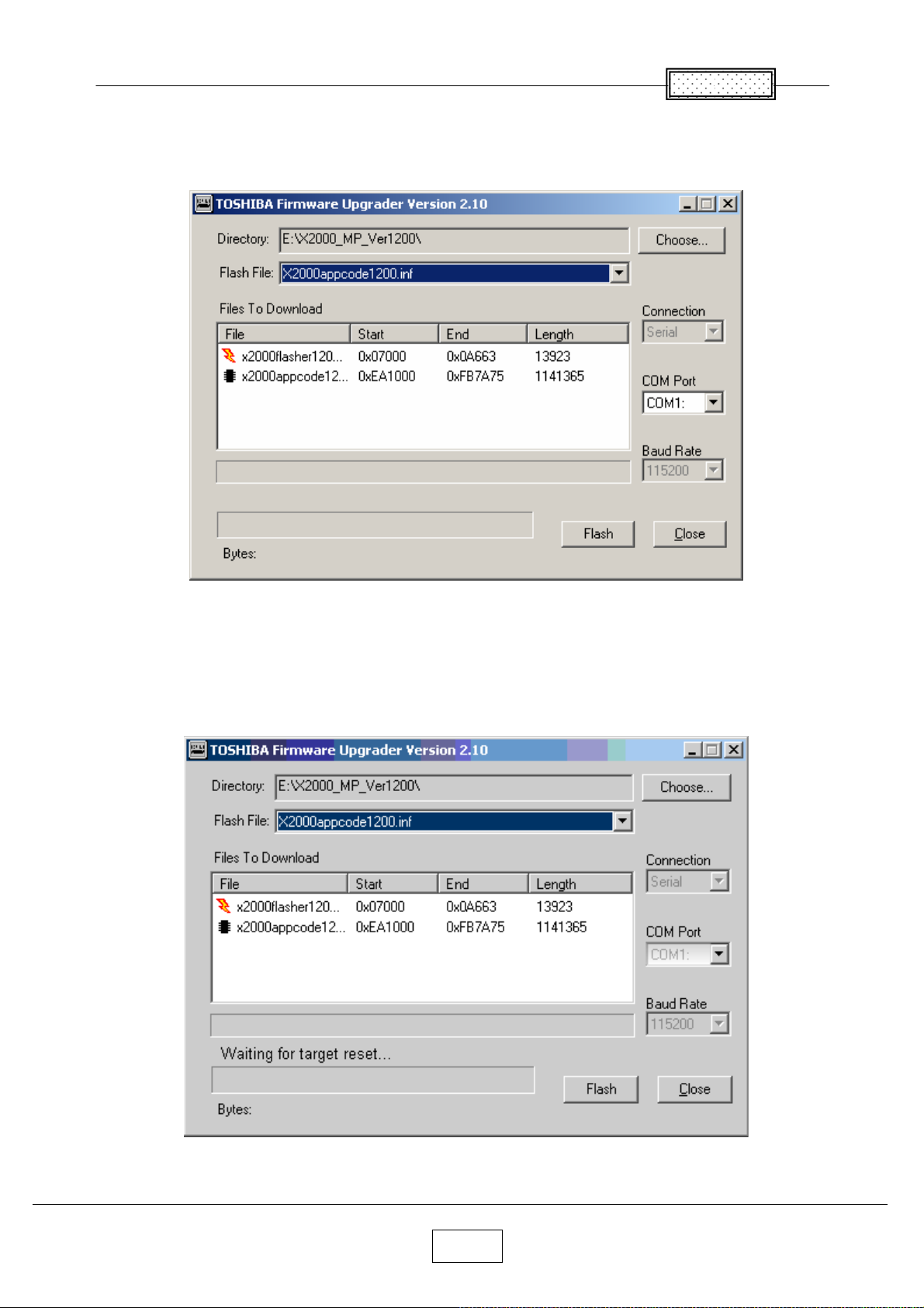
The upgrade file appears in the Select File box.
Select the COM port.
Chapter 4
Click Flash button.
4-2
Page 37
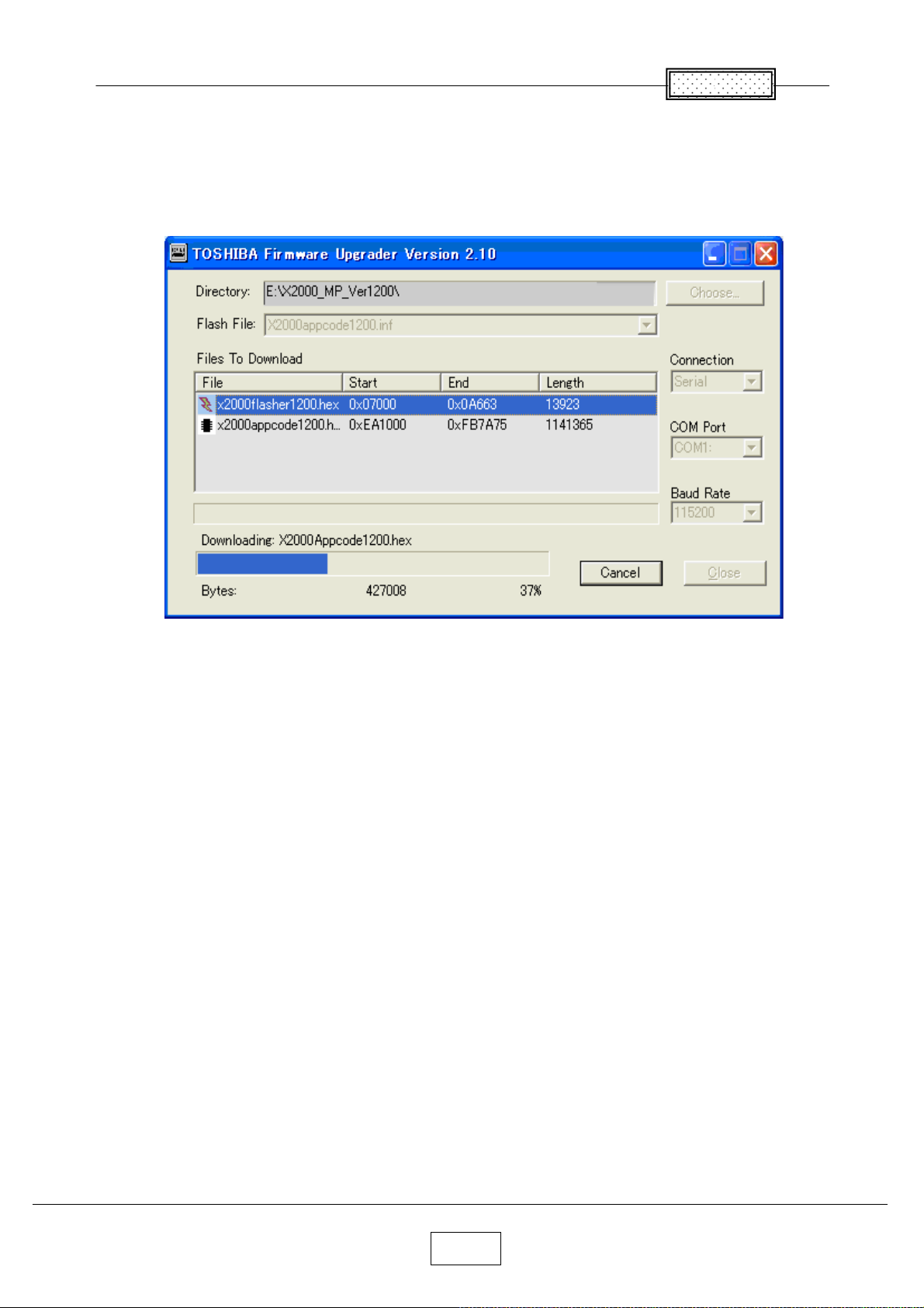
Chapter 4
Press and hold the projector’ s [Input] and [Keystone] keys, and then plug in the power cord.
The projector starts the Firmware upgrade,
[LAMP], [ON/Standby] and [TEMP] LED’ s are RED blinking.
The computer begins downloading the upgrade files to the projector.
The process may take several minutes.
4-3
Page 38
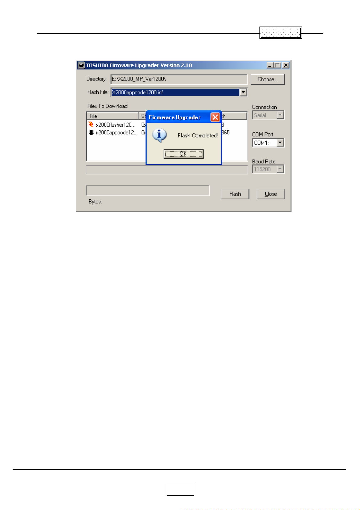
When the upgrade finishes normally, the following dialog box appears.
Chapter 4
Click the Close button.
The upgrade is complete.
4-4
Page 39
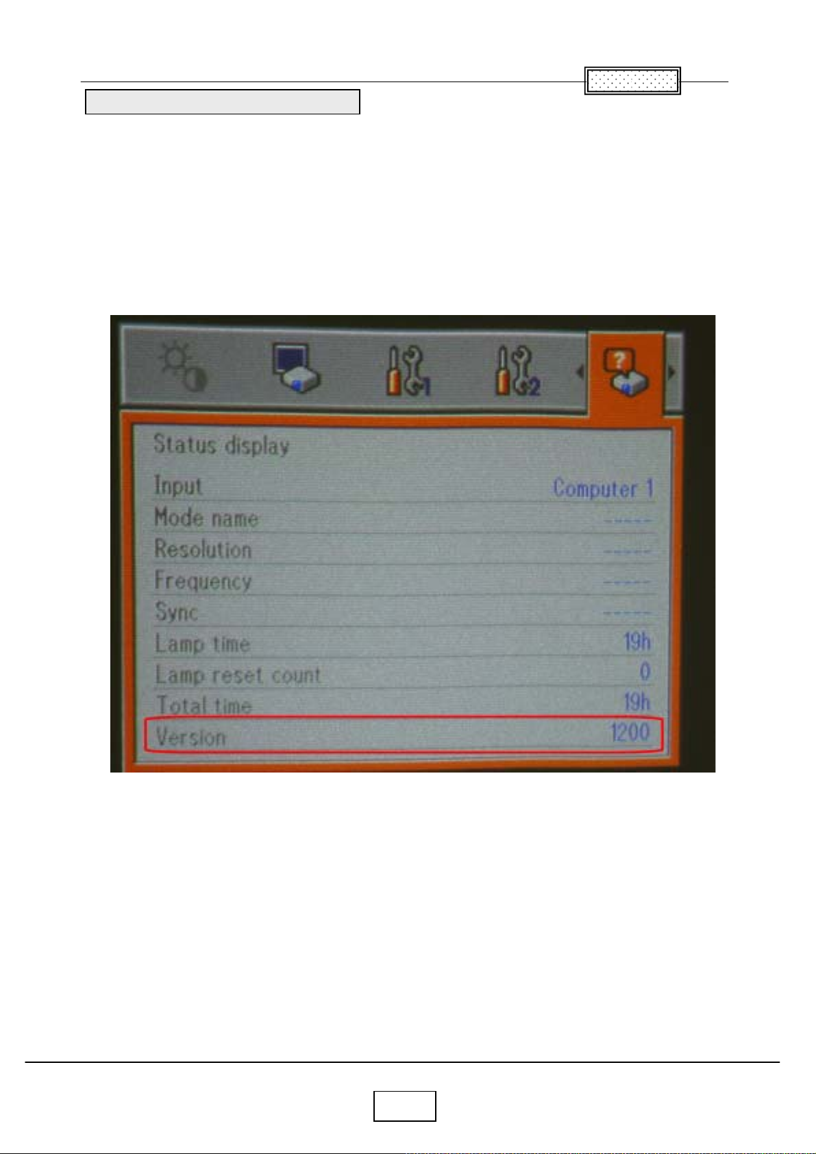
Confirm the software upgrade
1. Power up the projector.
2. On the projector keypad, press the MENU key to display the menus.
3. Press button Right or Left arrow to highlight Setting display.
4. The Setting display dialog box display the software version.
These should match the upgrade version you downloaded.
Chapter 4
4-5
Page 40
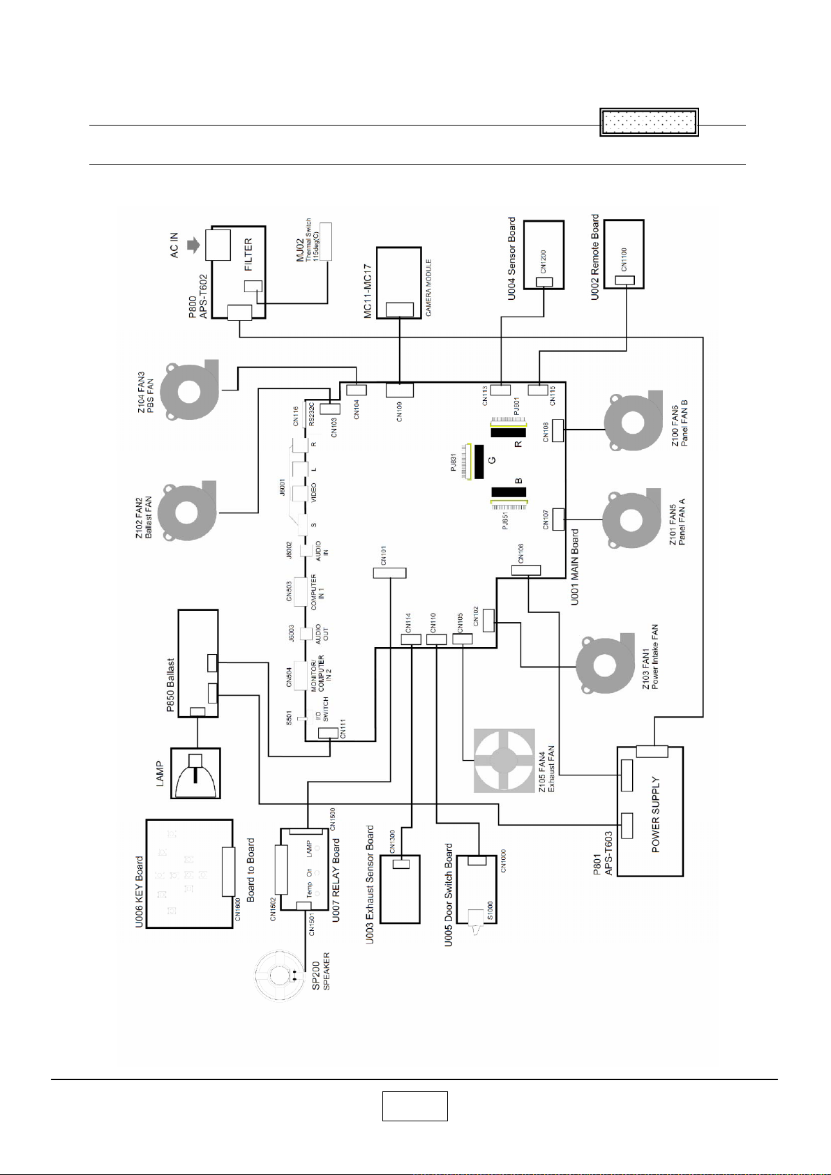
Chapter 5
Wiring Diagram
Chapter 5
5-1
Page 41
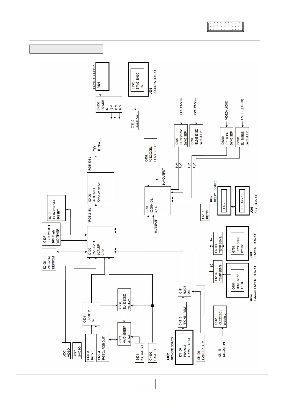
Block Diagram
BLOCK DIAGRAM 1/2
Chapter 5
5-2
Page 42
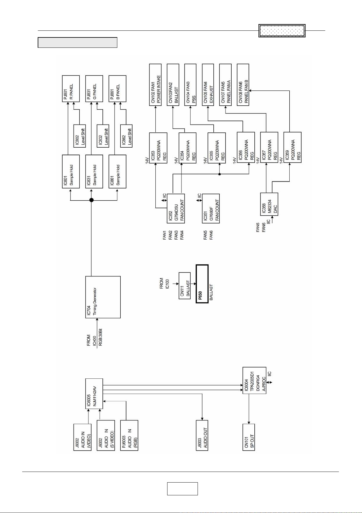
Block Diagram 2/2
Chapter 5
5-3
Page 43
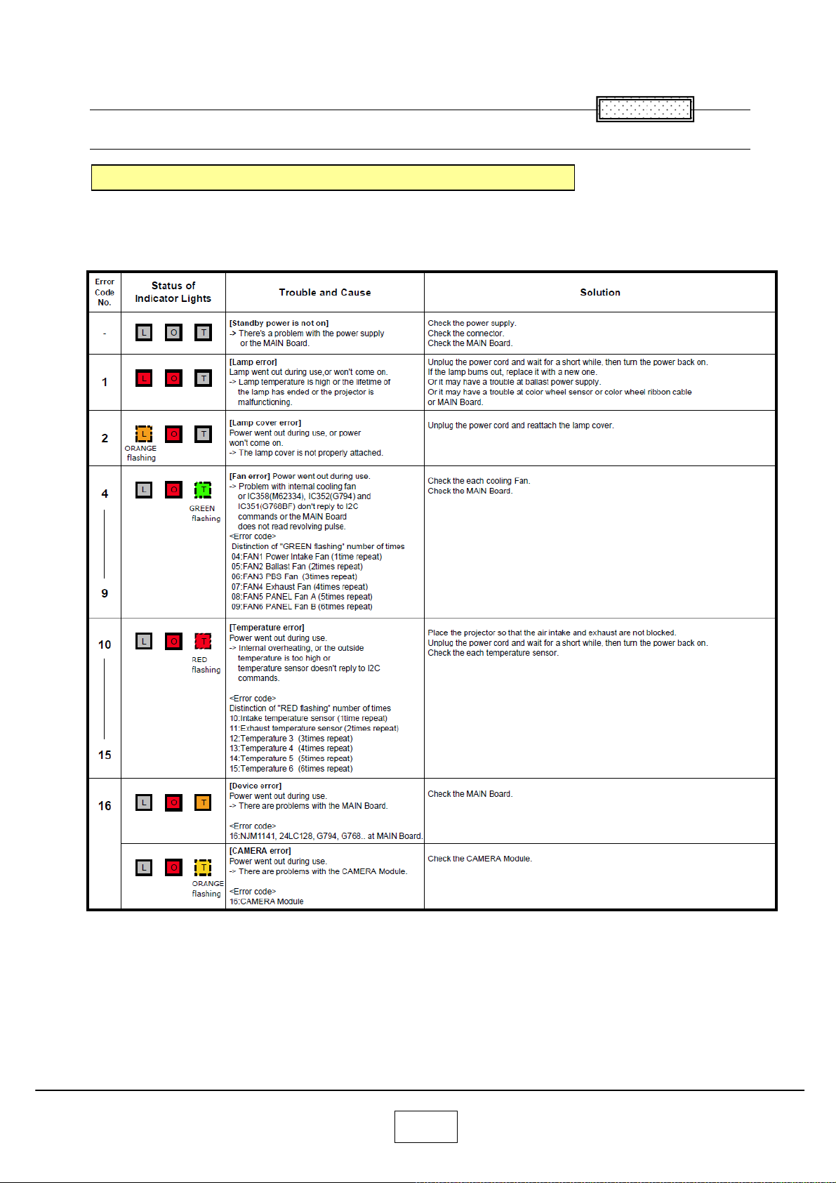
Chapter 6
6
LED Display
LED Display (Problems Shown on LED Indicator Combination)
Chapter
<Notes>
When each error occurs,after approx.one minute of abnormal display,
the projector turns to the standby state waiting for internal cool down.
[ L ] : LAMP, [ O ] : ON, [ T ] : TEMP
6-1
Page 44
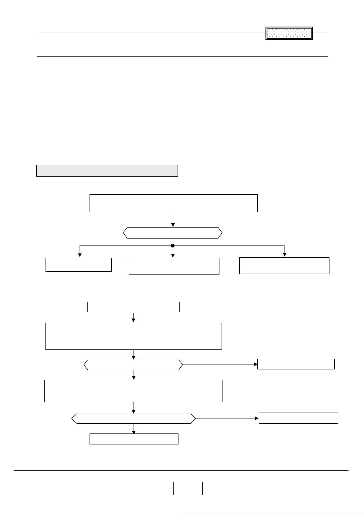
Troubleshooting
ou use this section to diagnose problems with the projector. Choose the problem you
Y
are trying to diagnose from the list below. The Power, Image and Audio sections
provide a variety of symptoms, while the other includes only one page.
1. For Power problems
2. For Image problems
3. For Audio problems
4. For Remote Control
5. For Keypad problems
6. For Menu problems
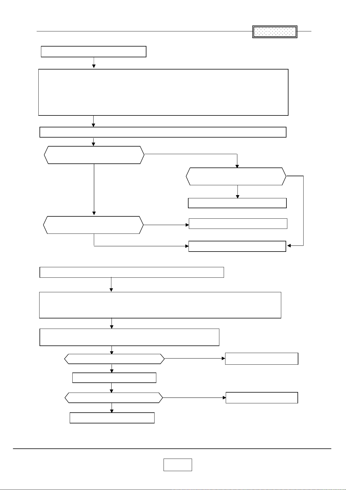
Troubleshooting Power Problems
The projector will not power up, only partially power up,
or will not remain powered up.
Chapter 6
What is the problem?
No stand by LED
No stand by LED
Check the Power cord and AC power outlet.
Check the Main power switch.
Check the Keypad cable has broken or not.
Check the connect cables inside the Unit.
No lamp
At least some fans are running.
Ye s
Does the projector power up?
No
Check the voltage of CN106 (Power IN) at Main board
And also check the voltage of CN201 (Power Out) at Power Supply
when it removes the cable from Main board.
Lamp or projector shuts off after
running a short period of time.
Problem resolved.
Is the power supply outputting?
Ye s
Replace the Main board
No
Replace the power supply
6-2
Page 45
No lamp
Check the error code log at service mode
When there is the error code, refer to the LED error List.
When the error code is Lamp error (No.1), remove the lamp to see if it looks good.
There should be no ruptures, no bulges, and no cracks in the reflector.
Substitute a known good lamp if you want to be absolutely certain that the lamp is not the problem.
Replace the lamp.
Check the color wheel motor cable and color wheel sensor cable are connected to the Main board.
Chapter 6
Does lamp enable measure low?
(CN 111 3 P I N )
No
Is 370V (DC) input
of Ballast OK?
370V (DC): CN102 1PIN (RED)
(POWER SUPPLY SIDE)
Ye s
Ye s
Replace the ballast
Are DC power voltage levels
OK on the Main board
Ye s
Lamp or projector shuts off after running a Short period of time.
No
Replace the power supply
Replace the Main board
Note:
This is usually a thermal issue caused by excessively high internal temperature.
The high temperature could cause a component on the Main board or the power supply to fail when it gets hot.
No
Check the error code log at service mode
When there is the error code, refer to the LED error List.
Ye s
Are all fans running?
No
Replace the broken fan.
Ye s
Does the projector run property?
No
Replace the power supply
6-3
Replace the Main Board
Problem resolved
Page 46
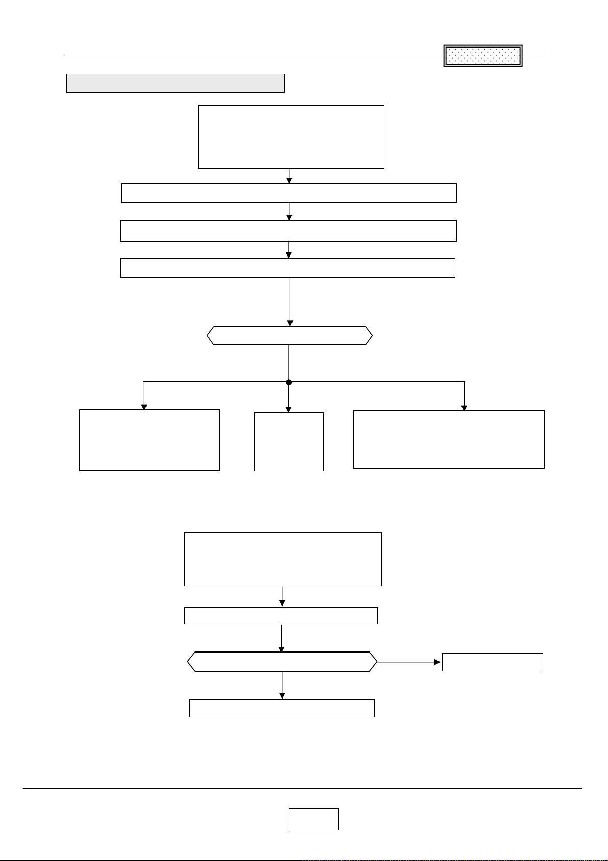
Troubleshooting Image Problems
The image is not correct.
The projector starts and runs normally.
The menus are accessible.
The lamp is lit.
Upgrade the software to the latest version or reinstall the projector software.
Confirm that all image adjustments are set to factory defaults
Confirm that the cable and source signal Are good.
What is the problem?
Chapter 6
No image at all.
Vertical or horizontal lines.
Sparkle picture.
Clusters of dark pixels.
Dim image
No image at all.
Vertical or horizontal lines.
Sparkly picture.
Clusters of dark pixels.
Replace the Main Board.
What is the problem?
No
Replace the optical engine
Bad or missing tint or color.
Missing logo,VGA,composite Video, or S-video.
Distorted image, noisy, rolling,torn,frozen,
” Plaid” repeated, or shifted image.
Ye s
Problem resolved
6-4
Page 47
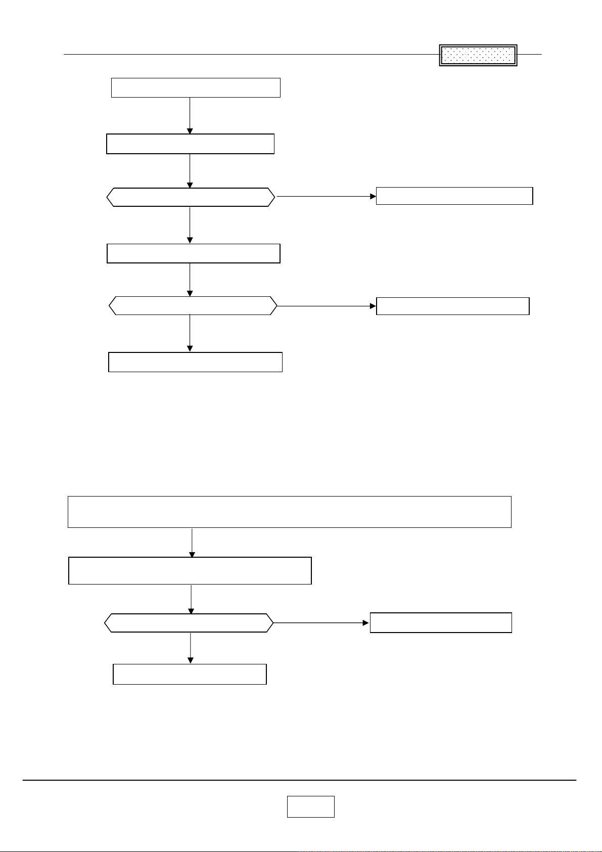
Dim image
Substitute known good lamp.
Image brighter?
No
Substitute known good Main board.
Image brighter?
No
Chapter 6
Ye s
Replace the lamp.
Ye s
Replace the Main Board
Replace the optical engine
Bad or missing tint or color.
Distorted image, excess noise, rolling, torn, frozen,” Plaid” image, repeated single image or shifted image.
Make sure cables are good.
Check the color wheel delay index value in the service mode.
Ye s
Image good?
Problem resolved
No
Replace the Main Board
6-5
Page 48
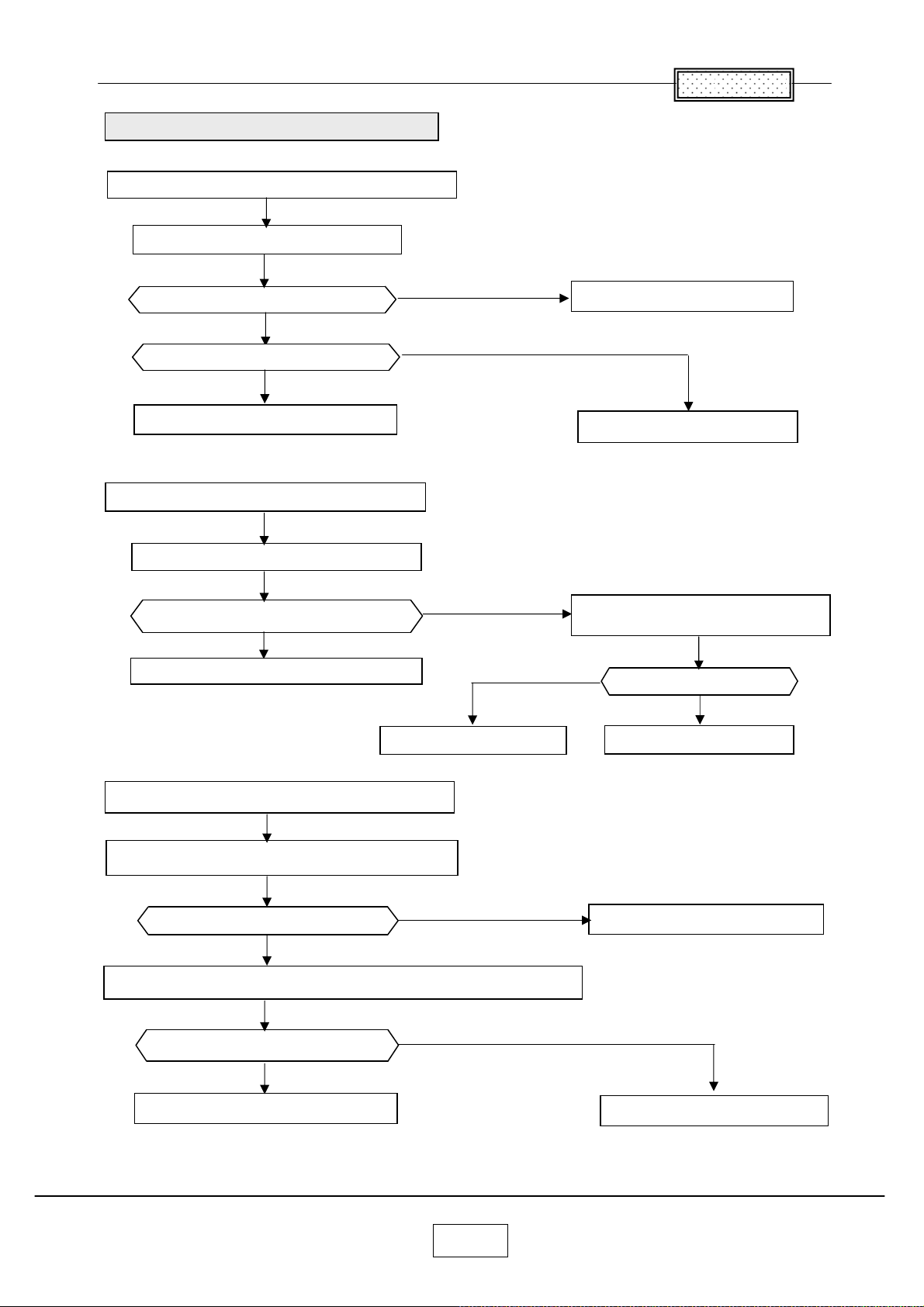
Troubleshooting Audio Problems
No audio or distored audio from the speaker.
Make sure cables are good.
Chapter 6
Is audio OK?
No
What is the problem?
No audio from the speaker
No audio from the speaker.
Check the speaker resistance.
Does it measure around 16 ohms?
No
Replace the speaker
Ye s
Ye s
Problem resolved
Audio is distoyed
Connect a known good 16 ohms speaker
in place of the existing speaker.
No
Is audio OK?
Ye s
Replace the Main board.
Audio sounds scratchy or distored.
Verify that audio signal source and cables are good.
Ye s
Sound good?
No
Connect a known good 16 ohms speaker in the place of the existing speaker.
Ye s
Sound good?
No
Replace the Main board.
Problem resolved
Problem resolved
Problem resolved
6-6
Page 49
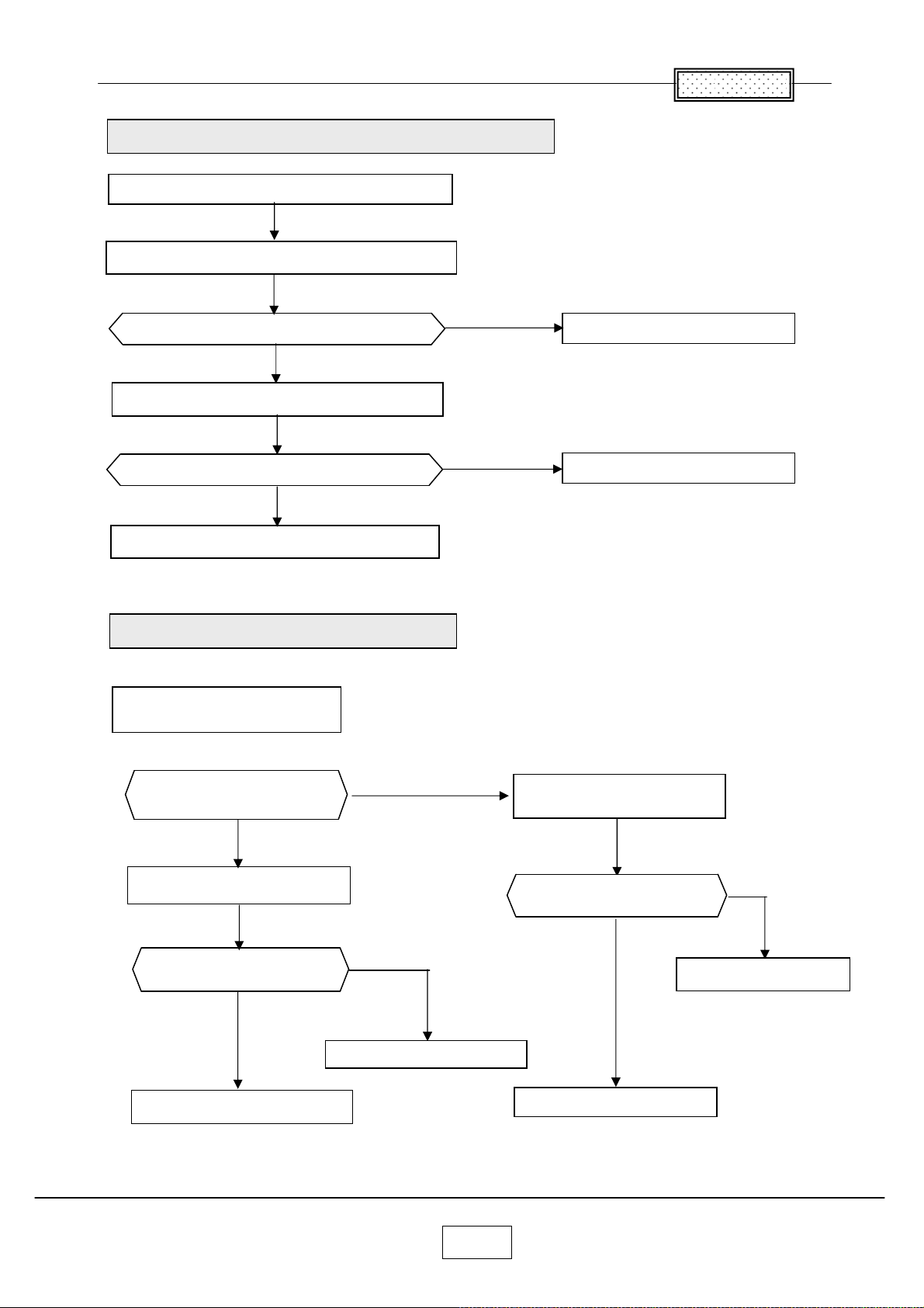
Troubleshooting Remote Controller Problems
Infrared Remote Problem
Install known good batteries in the remote controller.
Ye s
Does the remote work?
No
Use a known good remote with the projector
Chapter 6
Problem resolved
Does the remote work?
No
Replace the Main board.
Troubleshooting Keypad Problems
Keypad does not
respond to key presses.
Is a known good Key B.
available for substitution?
Ye s
Substitute the good key board.
No
Problem resolved
Substitute a known
good Main board.
Ye s
Does the projector
Respond the key presses?
Does the projector
respond the key presses?
Ye s
Replace the key board.
No
Replace the Main board.
6-7
No
Replace the Main board.
Replace the key board.
Page 50
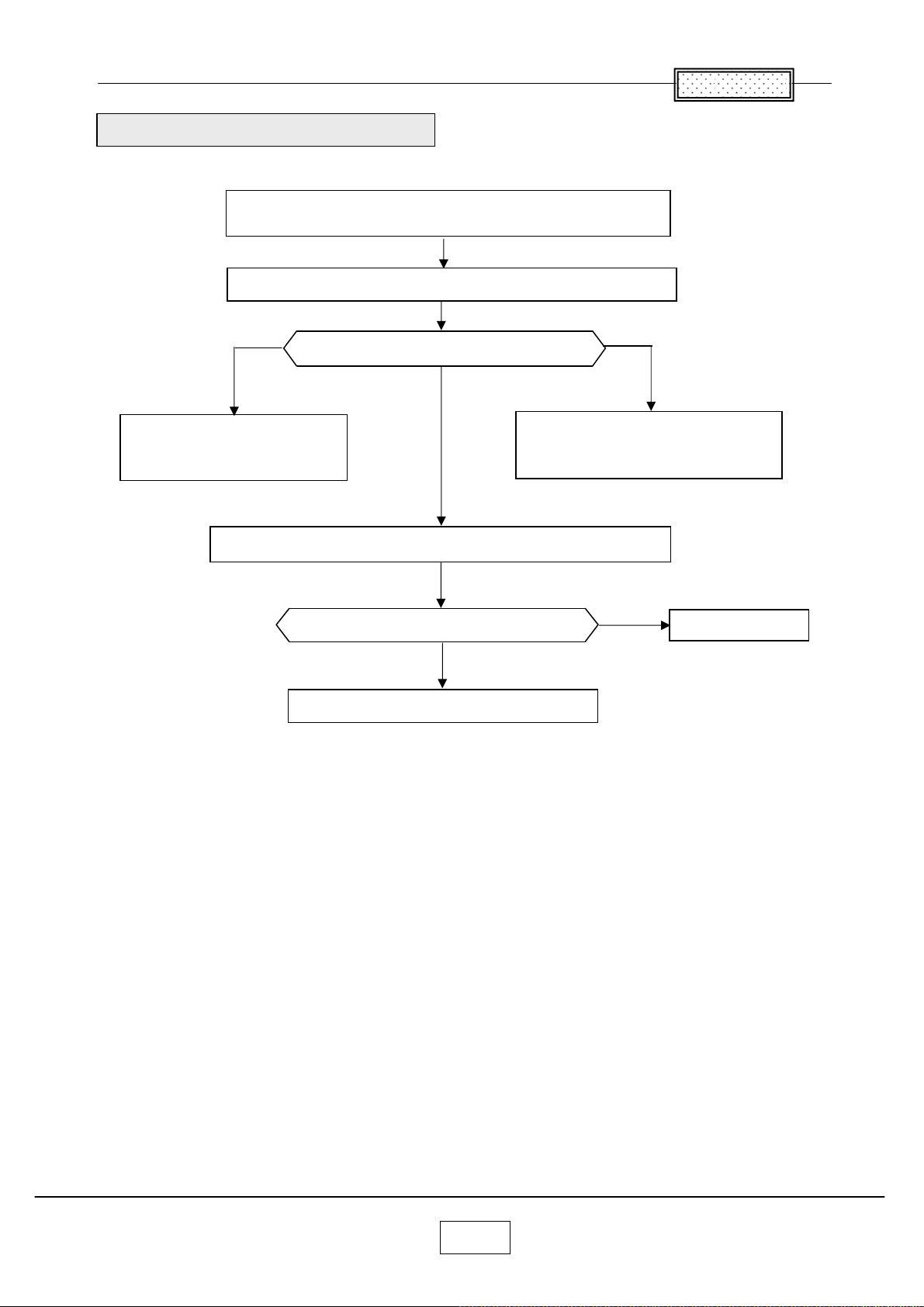
Troubleshooting Menu Problems
Menu does not appear on screen.
Startup screen and other images appear normal.
Try pressing the Menu button on both the remote and keypad.
Chapter 6
Ye s
If the remote works and
the keypad doesn’ t, go to
Troubleshooting Keypad problems
Flash or re-flash the latest software into the projector.
Does the menu appear?
No
Does the menu appear?
No
Replace the Main.board.
Ye s
If the keypad works and
the remote doesn’ t, go to Troubleshooting
remote control problems
Ye s
Problem resolved
6-8
Page 51
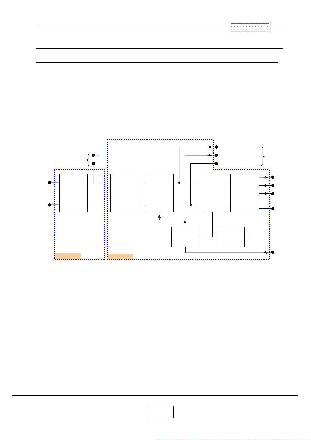
Chapter 6
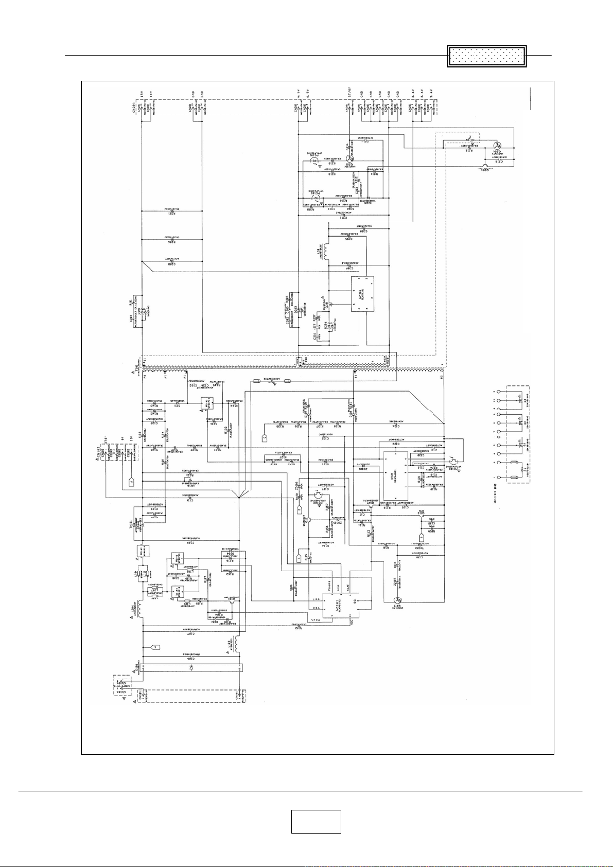
Operation of Power Supply (APS-M602)
OUTLINE
This power circuit APS-T60 is composed of 2 units as shown as below. (Fig.1)
APS-T602 is composed of AC inlet and input line filters mainly.
APS-T603 is composed of rectifier circuits, PFC circuit and DC/DC converter circuit mainly.
The power circuit APS-T60 is supplied 100~240Vac and it supplies 5 power sources to load
circuits.
In case of the typical operation, it supplies 370V (260W max.) and 16V as Non-isolated output and
supplies 3 outputs as isolated output. 3 isolated outputs are 6V, 14V and 17V.
In case of the standby mode, 16V line is turned off. And the voltage of 370V line is varied to
voltagethat
rectified the AC source.
3 isolated outputs are not turned off.
+370V (non-isolated)
+16V (non-isolated)
0V (non-isolated)
to Ballast
Bridge
Rectifier
Circuit
Power
Factor
Correction
(PFC)
Circuit
Primary
+16V line
Rectifier
Circuit
DC/DC
Switching
Converter
Secondary
Rectifier
Circuit
Feedback
Control
+17V
+14V
+6V
GND
ST/OP
(ON/OFF
Control)
6–9
Page 52

Chapter 6
OPERATION OF POWER SUPPLY
1. Transition from AC ON to Standby mode
When the AC source is supplied to this power circuit, the voltage rectified by D101 and smoothed by
C105 is supplied to VH pin of IC102 through R125.
VCC pin voltage of IC102 rises by current supplied to VCC pin through VH pin.
And then, IC102 starts up and the DC/DC converter begins to operate. (6V, 14V and 17V start up.)
* This DC/DC converter is a PWM switching circuit, which is composed of IC102, T201 and Q103 mainly.
2. Transition from Standby mode to Typical Operation mode
When the level of ST/OP pin in the connector CN201 is Low or open, only the DC/DC converter is in the
switching operation. Each output does not have the on/off control which works solo, except primary 16V
line. The voltage level of primary 370V line becomes voltage after smoothing through
circuit. (e.g. Input: 100Vac,
This status is standby mode.
When the level of ST/OP pin in the connector CN201 is High, Q105 is turned on through a photo-coupler
PC103, and then the primary 16V source is supplied to the Ballast and IC101 of PFC circuit.
Because VCC voltage of IC101 reaches
PFC circuit begins to operate. The voltage level of primary 370V line becomes approximately 370V which is
stable against variation of AC input voltage.
* ST/OP pin is a pin to control for switching mode between standby and typical operation.
Output: approx. 140Vdc)
threshold level of starting voltage, IC101 starts up activity and the
bridge rectifier
3. Protection against abnormal condition
If Overvoltage or overheat or overload happens, the DC/DC converter stops the switching operation by
putting IC102 into the latch mode. Every output (They are primary 16V, secondary 6V, 14V and 17V.) of
the DC/DC converter is turned off, and this is maintained. PFC circuit stops the switching operation
because +16V line which is power source for the control IC of PFC is turned off. The voltage of 370V line
varies to
About the latch mode of IC102
In normal operation, CS pin voltage of IC102 is clamped by an inside 4V zener diode.
Externally forcing CS pin voltage to increase to the threshold voltage, 8.2V, for the latch mode allows the
IC102 to stop its operation for protection.
When CS pin voltage reaches to 8.2V, the inside source in IC102 is turned off, and OUT pin (for gate
drive of FET in the DC/DC converter) is set to the Low level.
Then, the start-up circuit is activated again, and VCC voltage is held at approximately 22V. This status is
the latch mode of IC102. The latch mode is maintained as long as supply to VCC pin continues.
It takes time for the latch mode to be rest because charged C105 voltage is applied to the VH pin even if
IC102 have changed to the latch mode.
Cutting off the input voltage decreases VH pin voltage, supplying no current to the VCC pin.
Thereafter, the latch mode is reset when VCC drops below the OFF threshold level, 8V min.
voltage that rectified the AC source. (i.e. The boost stops.)
6–10
Page 53

Chapter 6
OPERATION OF EACH SECTION
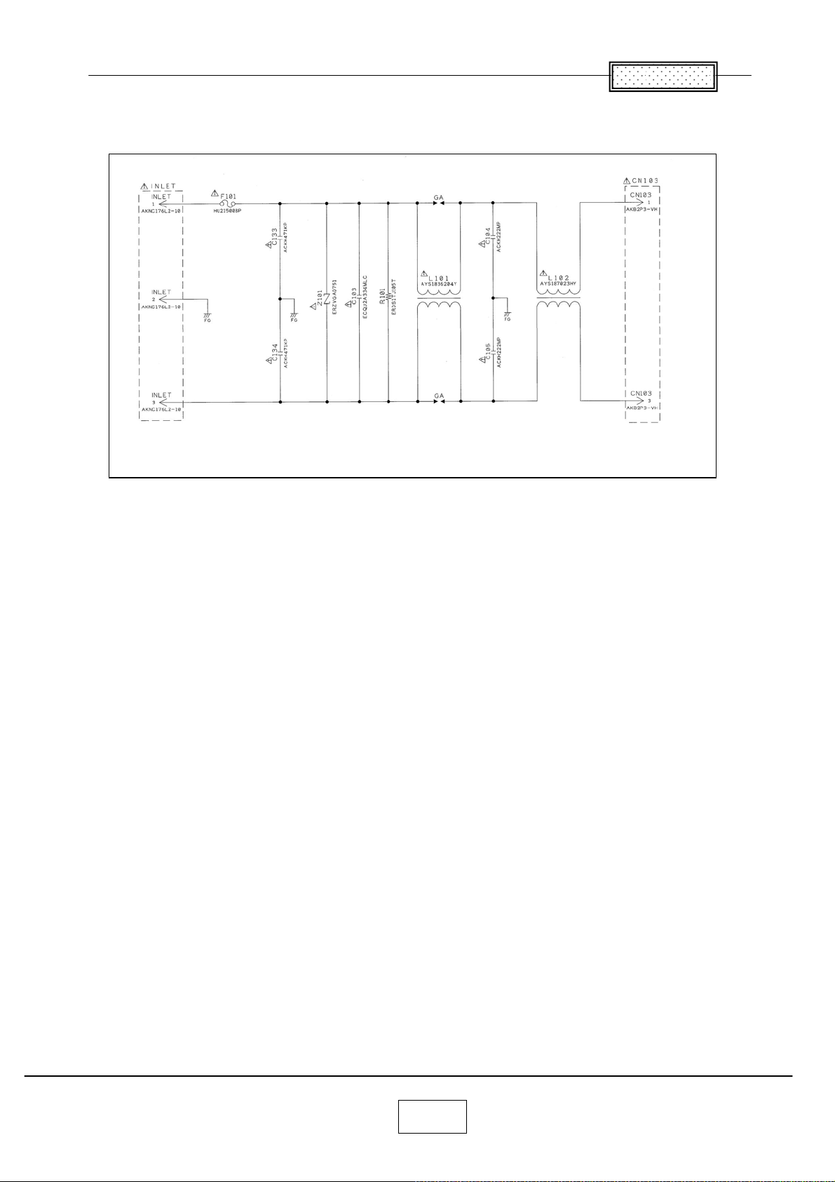
1. Input Line Filter
The Input line filter circuit is made up of capacitors (e.g. C1, C2, C101) and inductor chokes (e.g. L1, L2,
L101) on APS-T602 unit and a part of APS-T603 unit,
This section protects the noise generated by the power supply circuit from leaking out to AC line
and from entering of the external noise inside the power supply circuit.
This circuit is effective for both normal and common noise.
The fuse F1 becomes open in order to protect other parts, when excessive current flows in abnormal
conditions.
The connector CN2 is connected to thermal sensing element (e.g. thermal protector). Power Supply is
operated by CN2 shorted condition. In other words, when 2 terminals of CN2 become open by thermal
protector, power supply to subsequent circuit is shut off.
2. Power Factor Correction Circuit (PFC circuit)
The main parts of this switching converter are choke coil T101, switching MOSFET Q101, Q102, control
IC IC101 and diode D104. This circuit has mainly 4 functions as following.
a. Generate stable voltage
This PFC circuit operates so that the output always is set to 370Vdc(typ.). Actually, the switching
operation of Q101 and Q102 is controlled by IC101. Initial voltage setting of 370V output is set at
370Vdc(typ.) by VR101. (Input voltage: 100Vac, maximum load)
* Please don’ t turn although there are 2 variable resisters for this output voltage setup and for
the overvoltage protection setup. The case which needs to turn the volume means that the failure
mode cannot be repaired easily.
b. Reduce input harmonic current
Main purpose of Power Factor Correction Circuit is reducing input harmonic current by bringing the
input current waveform closer to a sine wave.
This circuit is CCM (Continuous Conduction Mode) PFC circuit which used resettable integrator.
The gate pulse width is adjusted per one cycle by detecting DC output voltage at the VF pin of IC101
and peak current at the ISNS pin of IC101. The amplitude and shape of the input current is controlled
so as to be proportional to and in phase with the input voltage.
c. Over current protection
The current sense pin ISNS of IC101 is the input to the current sense amplifier and the overcurrent
protection comparator.
There are essentially two levels of current limitation provided by the IC101. There is a “ soft” current
limit, which is essentially a duty cycle limiting fold back type: the converter duty cycle is limited to the
point where output power is limited and the output voltage begins to decrease. There is also a “peak”
current limit feature which immediately terminates the present drive pulse once the peak limit
threshold, = -1.0V, is exceeded.
d. Over voltage protection
The voltage in
the OVP pin of IC101.
drive signal.
proportion to output voltage by resistors R112, R113, R114, R115 and VR102 is added to
When the OVP threshold(7.49V(typ.)) is triggered, the IC101 will disable the gate
6–11
Page 54

Chapter 6
3. DC/DC converter
The main parts of this switching converter are transformer T201, switching MOSFET Q103, control IC
IC102 and output diodes D201, D202 and D203. This converter is Fly Back type.
This means that energy is transferred from the primary to secondary when MOSFET Q103 is off.
The main output is 6V line and auxiliary output is 14V and 17V line.
a. Start up
When AC input is supplied to this power supply unit, power source of IC102 is supplied through R125.
And then IC102 begins switching operation and the converter starts up.
Once the converter starts up, power source of IC102 is supplied from
b. Output Voltage Control
Output voltage is controlled by Pulse Width Modulation (PWM).
The voltage divided by R208, R209, R210 and R223 in the 6V line is detected, and this voltage is
compared with the reference voltage of shunt regulator IC201. Photo coupler PC101 feeds back the
comparison from secondary to primary. And output voltage is adjusted by the level of current drawn
from the FB pin of IC102.
When 6V output voltage is above the control level, IC102 to shorten the on-time (duty cycle) of
MOSFET Q103. This cause the average output to decrease. When the output is below the control
level, on-time (duty cycle) is increase, thereby increasing the average output voltage.
auxiliary winding of T201.
c. Overcurrent Protection
If the power supply output becomes overload, the current of MOSFET Q103 is limited by the maximum
threshold voltage of the IS pin in IC102 and output voltage drops. If the state continues as it is, an
overload protection function of IC102 operates to stop the IC in the latch mode.
d. Overvoltage Protection
Overvoltage state is detected when output voltage exceeds the zener voltage of zener diode (ZD201,
ZD202, ZD203). When zener diode is in conduction state, through the photo coupler PC102, the CS
pin voltage of IC102 is increased
shut down.
e. Overheat Protection
The abnormality of heat sink temperature of Q101, Q102 and Q103 is detected by PTC thermistor
PR101. Through the diode D113, the CS pin voltage of IC102 is increased
for the latch mode
overload or FAN-Locked.
and power supply is shut down. It operates at the time of abnormal state such as
forcibly to the threshold level for the latch mode. And power supply is
forcibly to the threshold level
6–12
Page 55
Chapter 6
6-13
Page 56
Chapter 6
6-14
Page 57
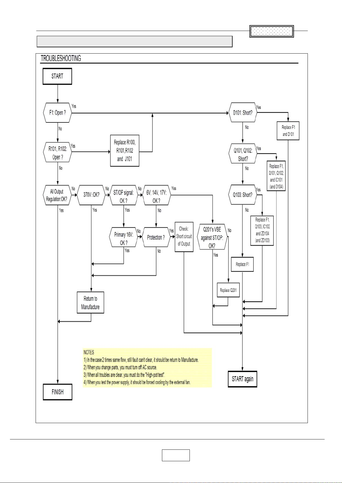
APS-M602 (ETXTS602MDA/MDE) Troubleshooting Faults
Chapter 6
6-15
Page 58
Chapter 7
A
Electrical Adjustment
Preparation
< Test equipment >
1) Personal computer
(Windows PC, OS: Windows 98SE, ME, 2000, XP)
2) Signal generating software
SINGOWS2000.MSI (Installer)
3) Adjustment software
DPJAdjustmentTool_2500.exe
4) Cables
RGB Cable and Control (RS232C) Cable
5) A protractor for Vertical Auto Keystone Calibration
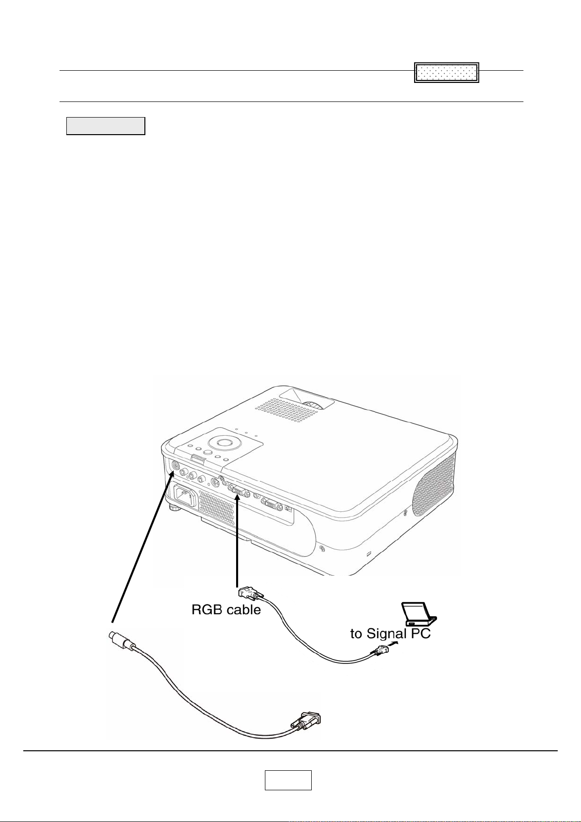
<For connection and setting of Personal computer>
1) Connection of personal computer
Connect the PC to computer 1 input and RS232C terminal as shown in following Fig.1
2) Set the screen resolution and refresh rate to XGA (1024x768) 60Hertz.
Set RGB output of the PC to CRT.
Chapter 7
Control cable
Fig.1
nd, to Control PC (the same PC)
7-1
Page 59
Adj
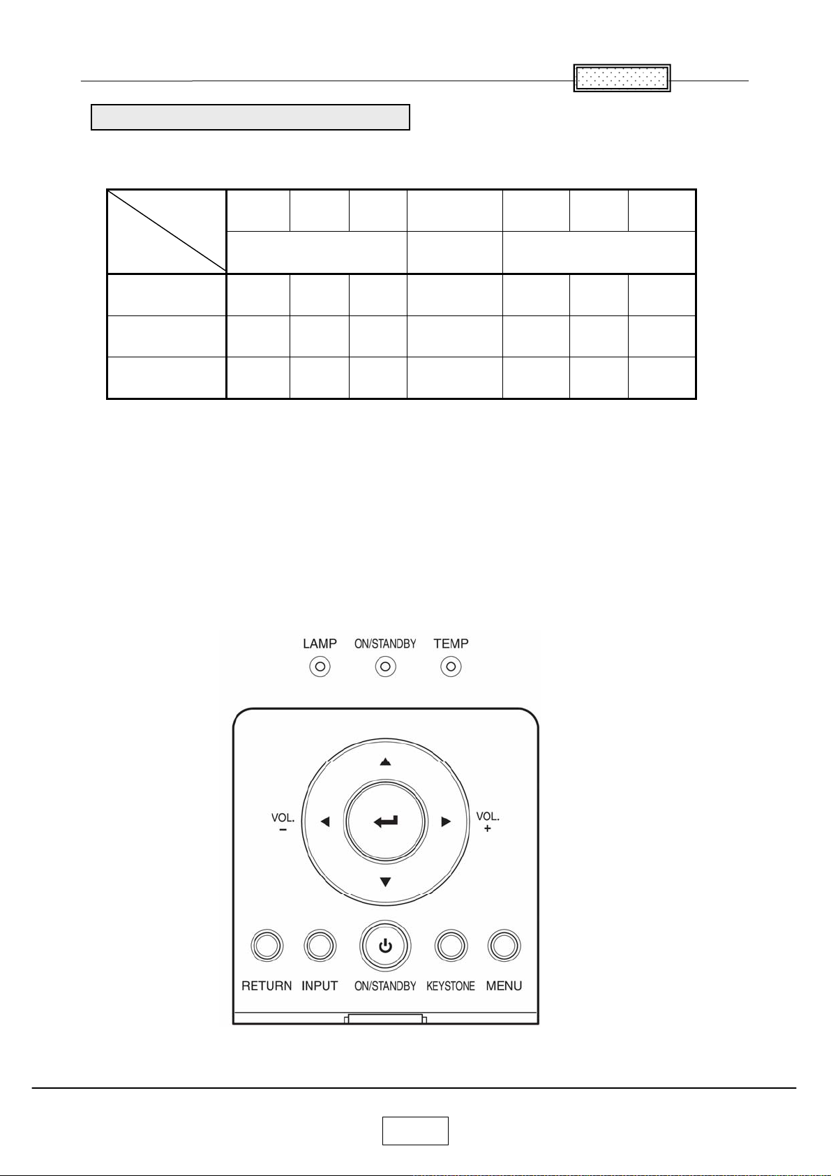
The table below shows you the items to be adjusted according to the type of part you replaced.
ustment Points vs Part Replaced
Adjustment
Parts
Keystone
Special Key Operations
Sub
Contrast
Altitude
Pixel
(Convergence)
SINGOWS
2000
VCOM Gamma Shading
DPJAdjustmentTool_2500.exe
Chapter 7
Main Board
Optical Engine
LCD Panel
×
× × × ×
× × ×
:Adjustment is needed
× :Not necessary
<SAVE DATA to EEPROM > (Common on all adjustment)
Press the buttons,
[Up], [Down], [Left] and [Right] simultaneously.
When these buttons are accepted, all LED’s light orange or red blinking in order.
7-2
Page 60

c
t
Proje
Plug in the power cord; turn on main power switch and the power of the projector.
or Setup
How to enter to the Factory Mode (TLP-X2500/XC2500/X3000/XC3000)
1) While the Volume adjustment bar is displayed on the screen, set value to [2],
and press the buttons,
[Input], [On/Standby] and [Keystone] simultaneously.
2) While the Volume adjustment bar is displayed on the screen, set value to [0],
and press the buttons,
[Input], [On/Standby] and [Keystone] simultaneously.
3) While the Volume adjustment bar is displayed on the screen, set value to [0],
and press the buttons,
[Input], [On/Standby] and [Keystone] simultaneously.
4) While the Volume adjustment bar is displayed on the screen, set value to [0],
and press the buttons,
[Input], [On/Standby] and [Keystone] simultaneously.
When the projector enters to the Service Mode, the buzzer beeps for 3 seconds.
If doesn’t beep, repeat from the beginning.
This mode maintains until you turn off the main power switch.
Chapter 7
7-3
Page 61
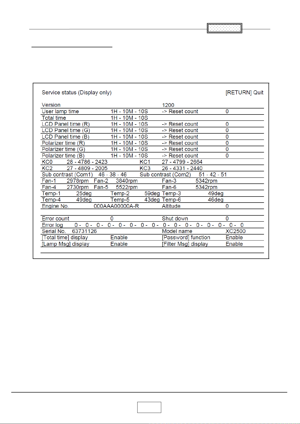
How to display the Service status
After the projector has entered to the factory mode, press the buttons,
[Return] and [Up] simultaneously. Then, the following display appears.
If it doesn’t appear, repeat from the beginning.
This mode maintains until you turn off the Main power switch.
Chapter 7
FAN-1 is Z103 (Service part location No.). FAN-2 is Z102.
FAN-3 is Z104. FAN-4 is Z105. FA N-5 is Z101. FAN-6 is Z100.
Temp- 1 is Intake temperature. Te mp-2 is Exhaust temperature.
A number of Error log means an error ID.
7-4
Page 62
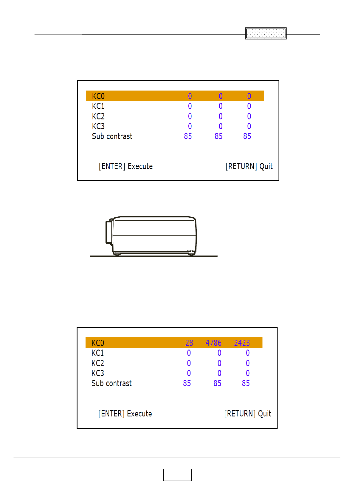
<Keystone Calibration>
Press [Input] and [Up] buttons simultaneously.
For it initialize the value, Press [Keystone] button.
Set the projector on a level surface.
Press [Enter] button of the projector.
When the adjustment is successfully completed, values changes from default [0].
(Example: The following menu)
If it fails, values don’t change from default [0].
Chapter 7
7-5
Page 63
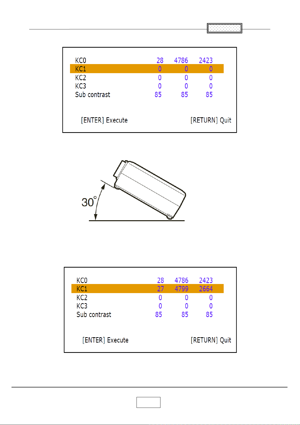
Select the KC1 item by pressing [Down] button.
Keep projector on 30 degree.
Press [Enter] button of the projector.
When the adjustment is successfully completed, values changes from default [0].
(Example: The following menu)
If it fails, values don’t change from default [0].
Chapter 7
7-6
Page 64

Select the KC2 item by pressing [Down] button.
Keep projector on -30 degree
Press [Enter] button of the projector.
When the adjustment is successfully completed, values changes from default [0].
(Example: The following menu)
If it fails, values don’t change from default [0].
<Note> When the projector is not tilted accurately +/- 30degree,
the adjustment values ([KC1] and [KC2]) do not change.
Chapter 7
7-7
Page 65
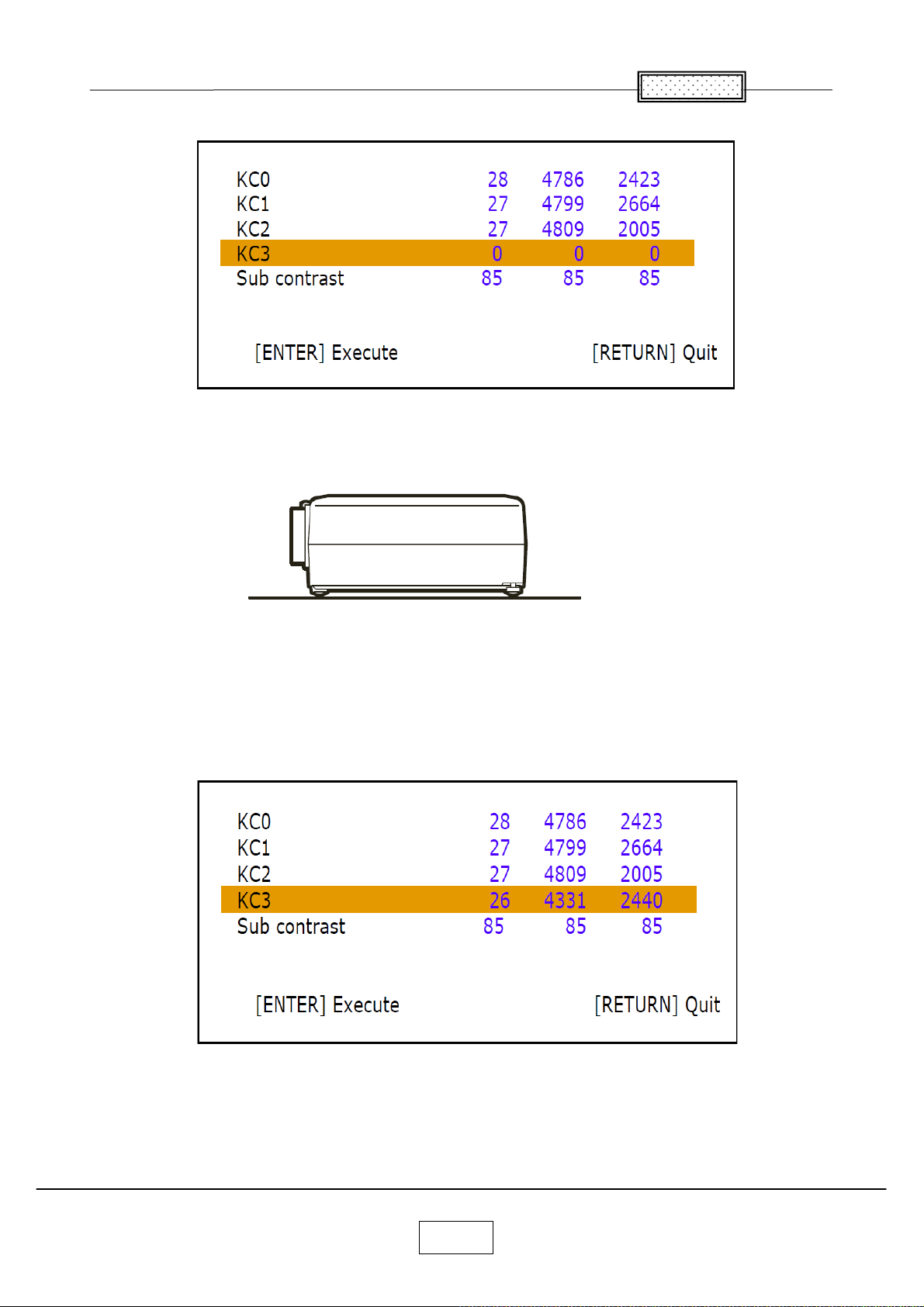
Select the KC3 item by pressing [Down] button.
Set the projector on a level surface and perform heat-run for 30 minutes or more.
Press [Enter] button of the projector.
When the adjustment is successfully completed, values changes from default [0].
(Example: The following menu)
Chapter 7
7-8
Page 66
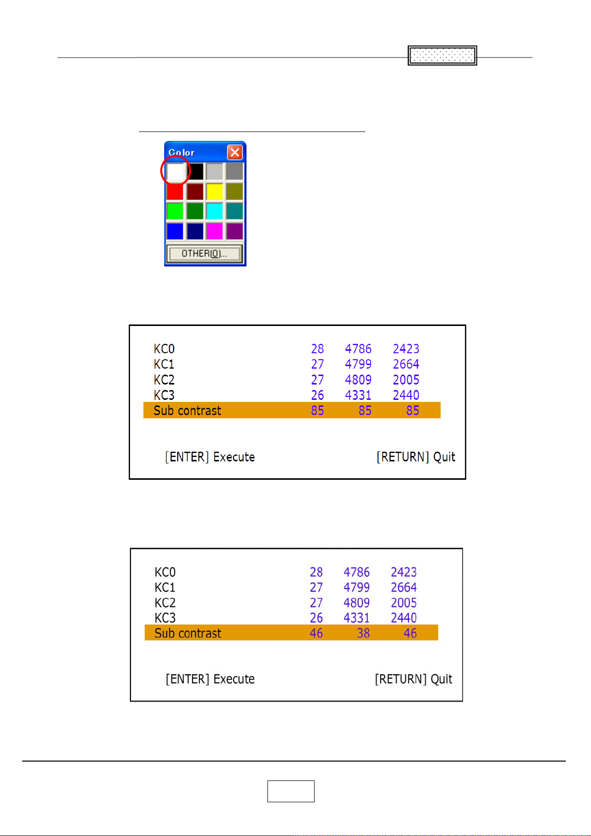
<Sub Contrast>
Right - click to display the following color pallets. Click [White] button.
Note: Move the mouse cursor out of a screen to avoid the error
Select the Sub contrast item by pressing [Down] button.
Press [Enter] button of the projector.
When the adjustment is successfully completed, values changes from default [85].
(Example: The following menu)
If it fails, values don’t change from default [85].
Adjust Computer-1 input and Computer-2 input both.
.
Chapter 7
7-9
Page 67
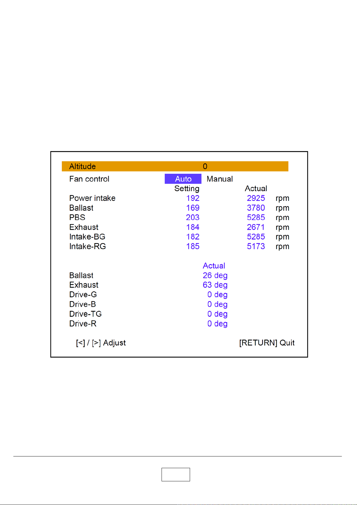
<Altitude>
Press [On/Standby] and [Up] buttons simultaneously.
For it initialize the value, Press [Keystone] button.
Select proper value by pressing the [Left] or [Right] button.
Factory setting is 0.
The value 1 is more than 500m (1,640ft) and under 1,000m (3,281ft).
The value 2 is more than 1,000m (3,281ft) and under 1,500m (4,921ft).
The value 3 is more than 1,500m (4,921ft) and under 2,000m (6,562ft).
The value 4 is more than 2,000m (6,562ft) and under 2,500m (8,202ft).
The value 5 is more than 2,500m (8,202ft) and under 3,000m (9,843ft).
The value 6 is more than 3,000m (9,843ft).
For example, in case of 2,700m altitude set the value to 5.
Press [Return] button.
7-10
Page 68
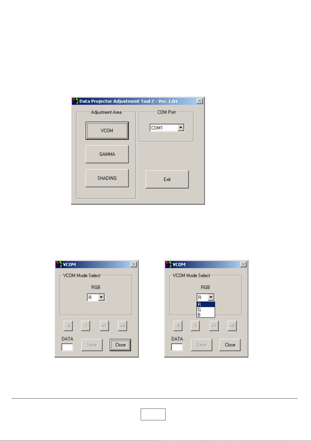
<VCOM>
Connect the control cable to the control terminal on the projector.
Then plug the RS232C connector on the other end of the cable into a RS232C port on the computer.
Open Windows Explorer navigate to the location where you stored the Adjustment file,
and then double click the DPJAdjustmentTool_2500.exe.
The startup window appears.
Select the COM port. and click the [VCOM] button.
The following window appears.
Select the “R”.
7-11
Page 69
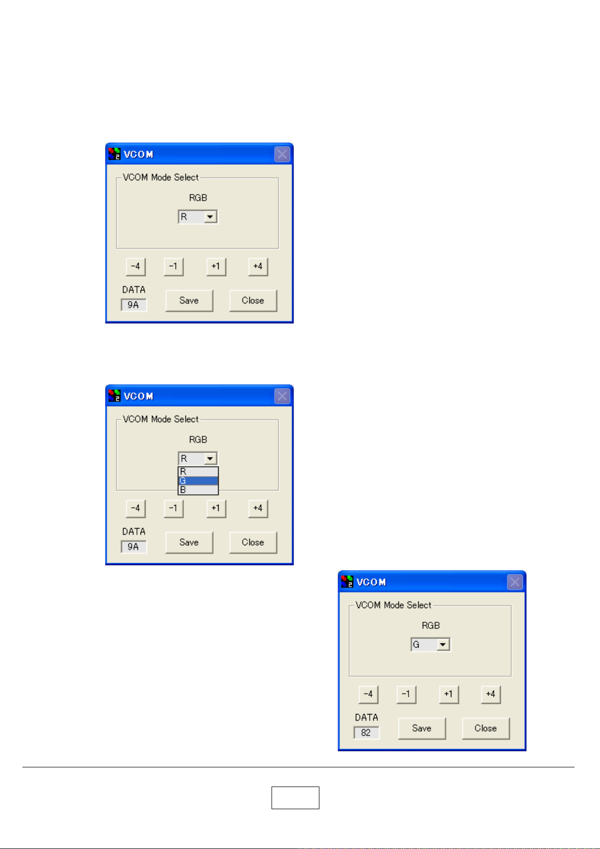
The current data is displayed in DATA column.
Push (+1) or (-1) button.
Adjust the data to reduce the flicker to its minimum point.
By pushing the (+4) or (-4), the data is adjusted in greater steps.
After the adjustment, click the [Save] to save the data.
Select the “G”.
The current data is displayed in DATA column.
Push (+1) or (-1) button.
Adjust the data to reduce the flicker to its minimum point.
By pushing the (+4) or (-4), the data is adjusted in greater steps.
After the adjustment, click the [Save] to save the data.
7-12
Page 70
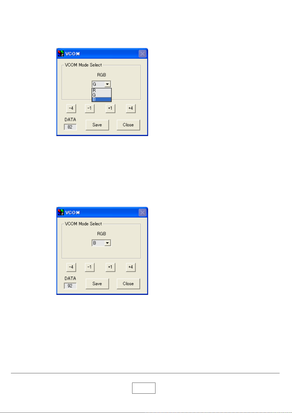
Select the “B”.
The current data is displayed in DATA column.
Push (+1) or (-1) button.
Adjust the data to reduce the flicker to its minimum point.
By pushing the (+4) or (-4), the data is adjusted in greater steps.
After the adjustment, click the [Save] to save the data.
When adjustment of R, G and B finishes, click the [Close] button.
7-13
Page 71
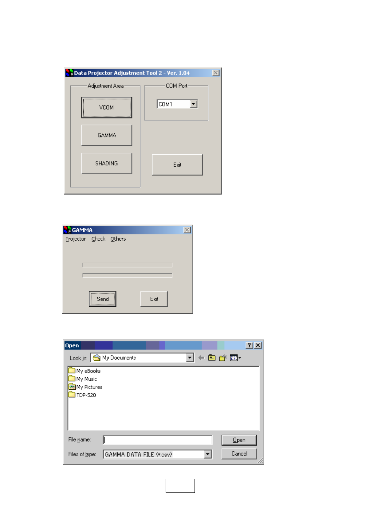
<Gamma>
Click the [GAMMA] button.
The following window appears.
Click the [Send] button.
Select the Gamma data file and click the [Open] button. (There are two files for R-type LCD and L-type LCD.)
7-14
Page 72
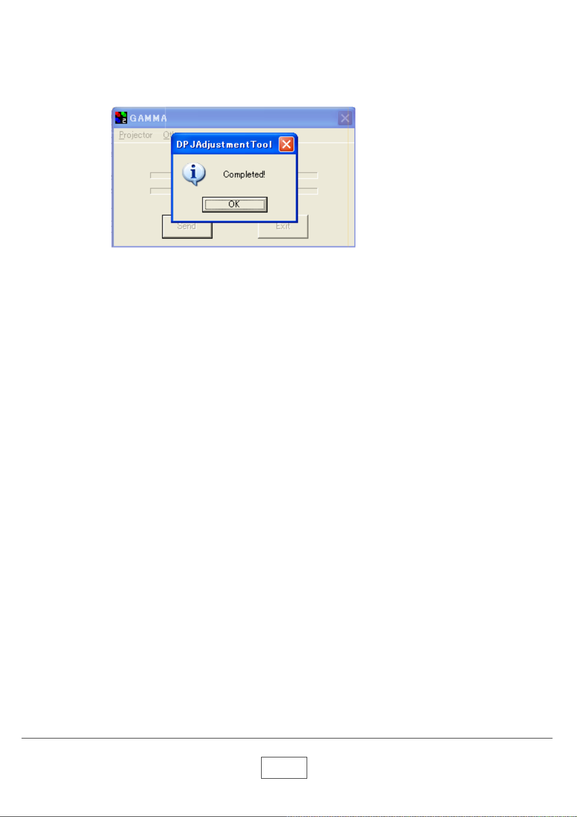
After the transfer is completed, the following message appears.
Click [OK] button.
The transferred gamma data will be automatically saved.
7-15
Page 73
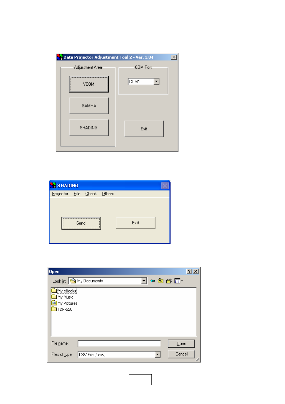
<Shading>
Click the [SHADING] button.
The following window appears.
Click the [Send] button.
Select the Shading data file and click the [Open] button. (There are two files for R-type LCD and L-type LCD.)
7-16
Page 74
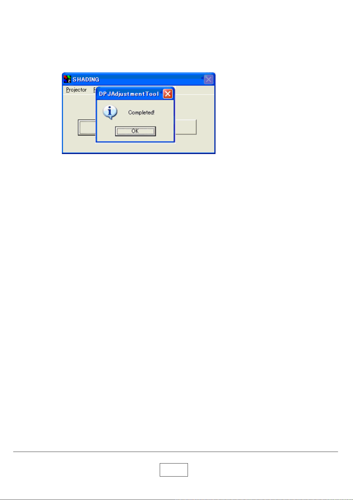
After the transfer is completed, the following message appears.
Click [OK] button.
The transferred shading data will be automatically saved.
7-17
Page 75
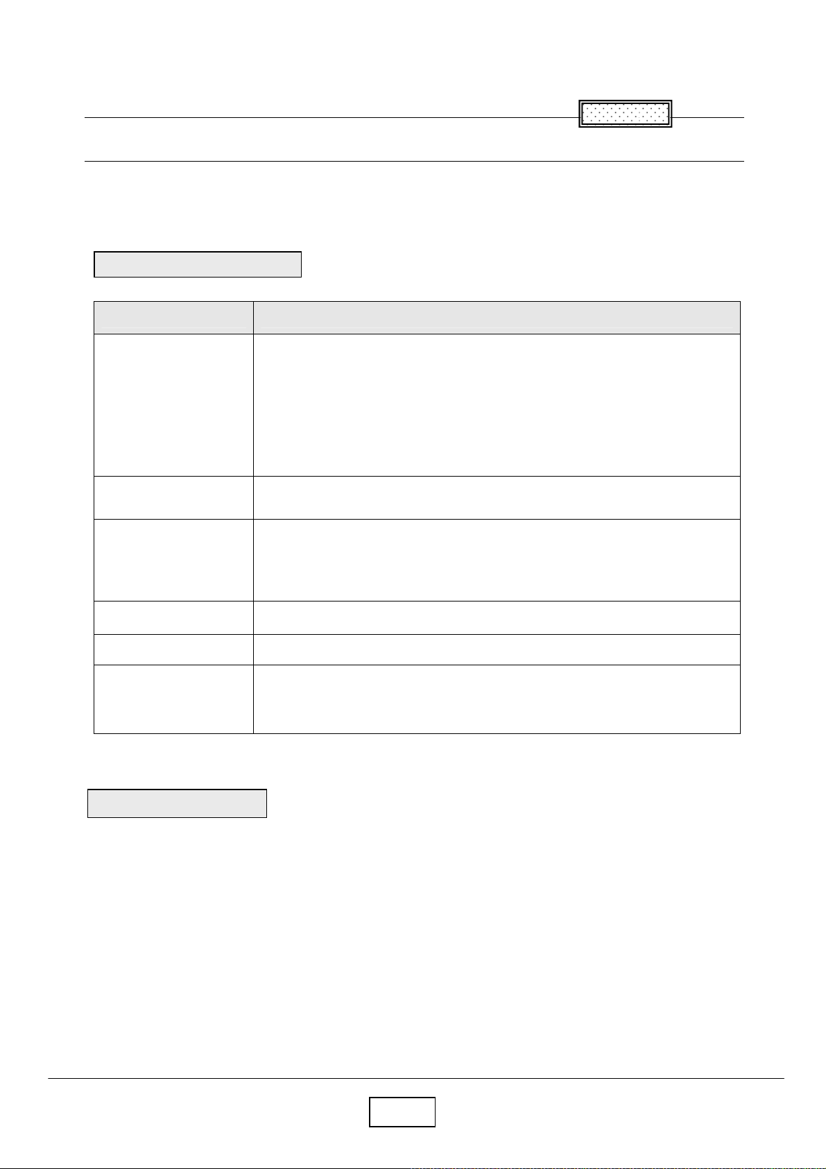
Chapter 8
8
Chapter
Functional Test
You perform the functional tests after you’ ve repaired the projector to make sure
All components of the projector operate properly.
You can also perform the functional tests if you’ re having trouble determining what is wrong with the projector.
Required Equipment
Equipment Notes
Video player Make sure the video player has an S-video Out port and cables.
The player should also have a Composite video port (RCA).
Toshiba strongly suggests you use a DVD player to test the Video quality. DVD players
reproduce colors better and project Sharper images. The least preferable is a VCR.If
you must use a VCR, make sure you use a commercially produces recoding
not one recorded from a broadcast source.
The VCR must include an S-Video connector in addition to a composite connector.
Commercially produced
video
Cables 1. RCA Pin jack cable for Composite video & audio.
Remote control Ensure that the remote has fresh AAA batteries.
Projector screen Use a flat screen, not a curved one.
Personal computer (PC)
You’ ll need the video in DVD, etc. format.
2. S-video cable.
3. RGB cable that come with the projector.
4. 3.5mm mini-jack cable for PC audio.
The stereo audio card should have either a 3.5mm stereo audio Jack or RCA left and
right output ports. The PC must have a CD-ROM and must have outputs for RGBHV,
VESA, D-sub15pin.
Before beginning
Make sure the work surface where you perform the functional tests is level and clean.
Place the projector on a soft surface (such as an anti-static mat) when running the tests.
Connect the following the I/O panel on the projector.
1. Video player through Composite Video and S-video ports.
2. Audio sources through Audio ports (RCA) or 3.5mm mini-jack.
3. Personal computer through RGB cable
.
8-1
Page 76
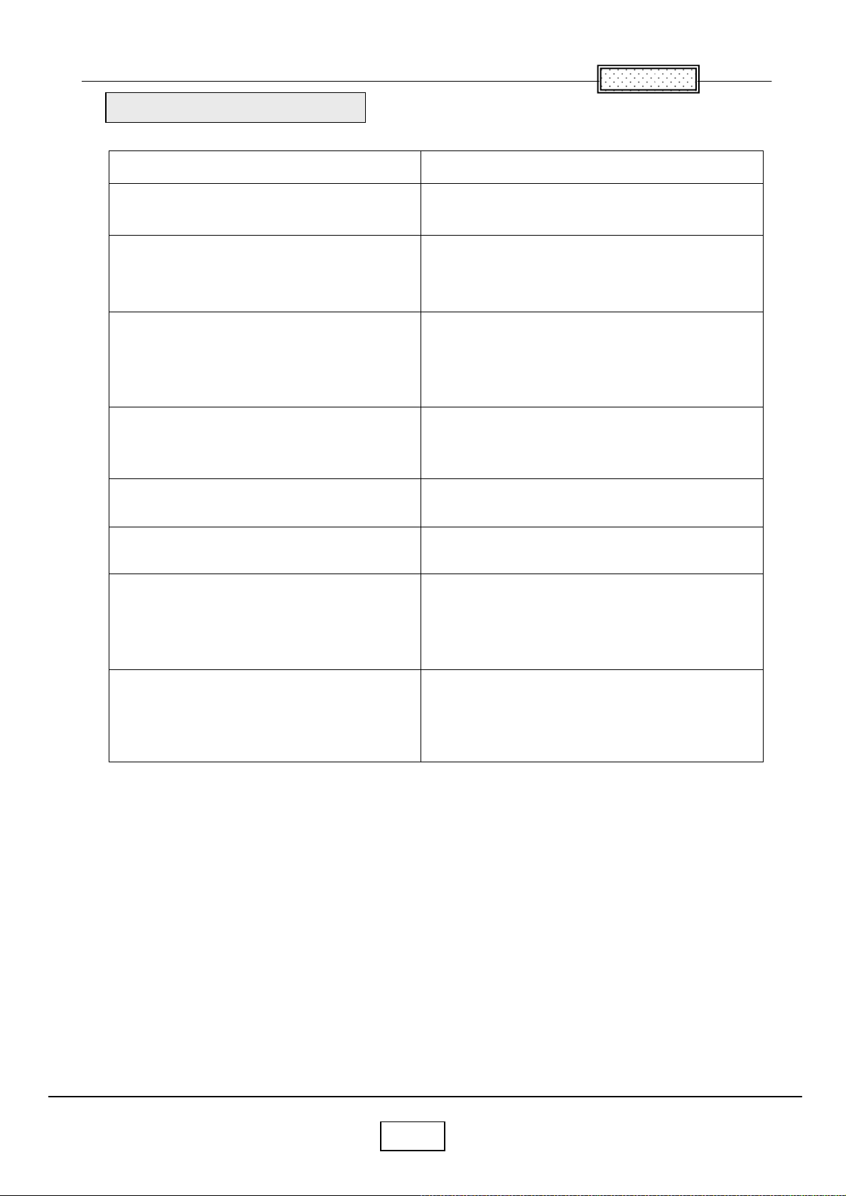
Perform the following tests
Test Verification
Chapter 8
Power Up
Connect AC power, and turn the unit on.
Cosmetics and mechanicals
Adjust the projector so that the image is Square.
Make sure the lens is at a 90 degree angle to the wall.
Composite video from video source
Connect the yellow composite (RCA) video Connector to
the projector. (Ensure that no other video source is
connected to the projector)
S-Video from video source
Connect the S-Video cable to the projector.
Disconnect the yellow composite (RCA) Video connector.
Image keystone adjustment
Connect a video source to the projector.
Audio from audio source
Connect the audio cable to the projector.
Manual source selection
Manually select a connected source.
Verify that the proper splash (logo) screen Appears.
Verify image quality.
Verify that the elevator and leveling foot Are functional.
Verify that the focus and zoom rings operate properly.
Verify cosmetics.
Verify that the video automatically synchronizes.
Verify there is no distortion, noise or other abnormalities.
Verify that the video automatically synchronizes.
Verify there is no distortion, noise or other abnormalities.
Verify that image responds properly when
You adjust the keystone setting.
Verify that audio source plays through the projector’ s speaker.
Verify that the volume controls function correctly.
Verify that the projector switches to the manually-selected
source.
Verify that the video automatically synchronizes.
Verify there is no distortion, noise or other abnormalities.
Software Version / Lamp time Used
Navigate through the Basic menu to the Setup menu.
Navigate to the Service menu.
Select info from the Service menu.
Verify software version
Verify the keys are not sticky.
Verify that the software version is current and that the lamp
is within its service life.
8-2
Page 77
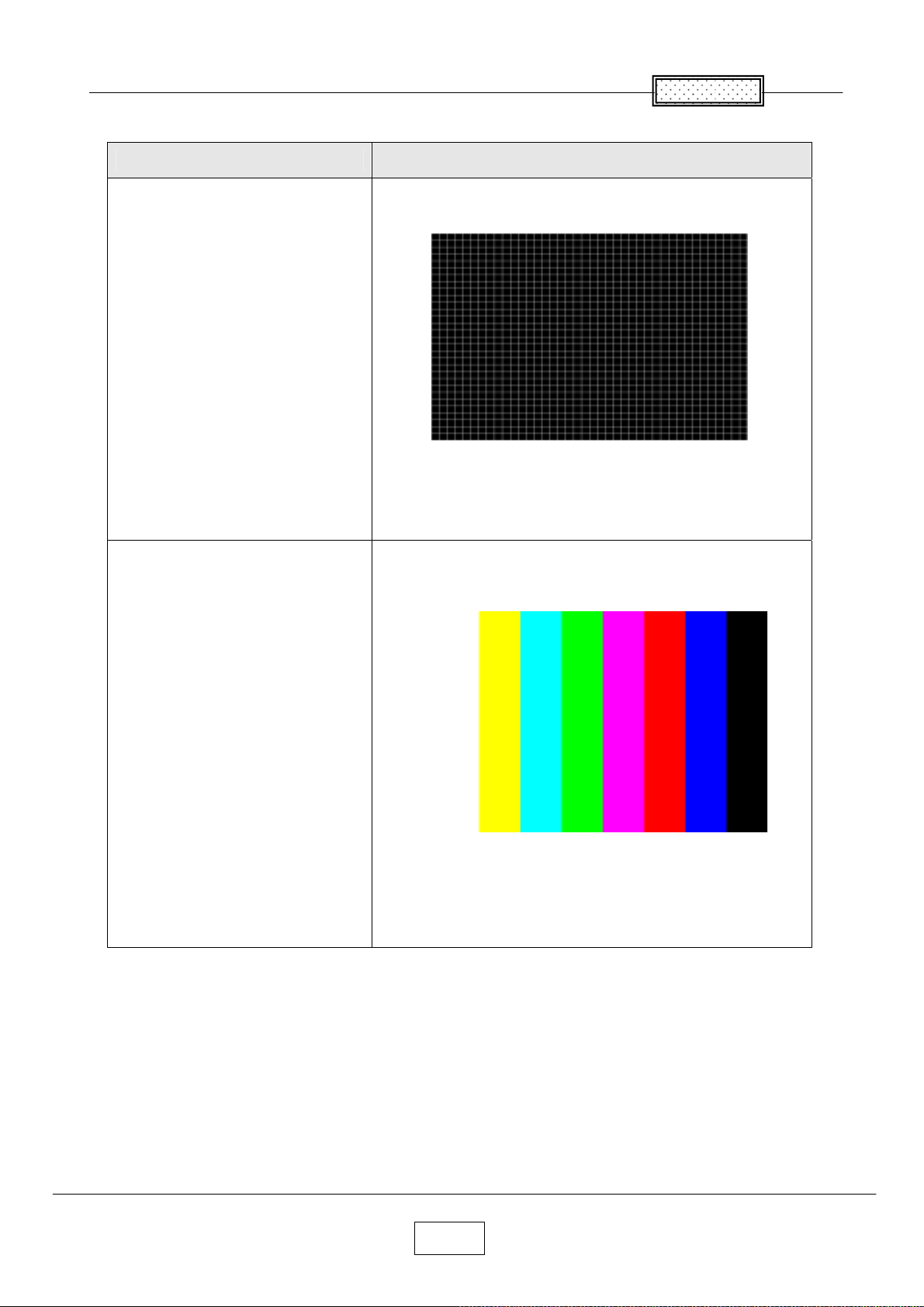
Test Verification
Chapter 8
Focus
SINGOWS2000
Cross Hatch image.
Color Wheel Index Delay
SINGOWS2000
Color bar image.
Verify that the image synchronizes properly through the computer 1 input.
Verify that image focuses through the full zoom range.
Verify there are no problems.
Verify that the image synchronizes properly through the computer 1 input.
Verify that the color is located in a line.
Verify there are no problems
8-3
Page 78
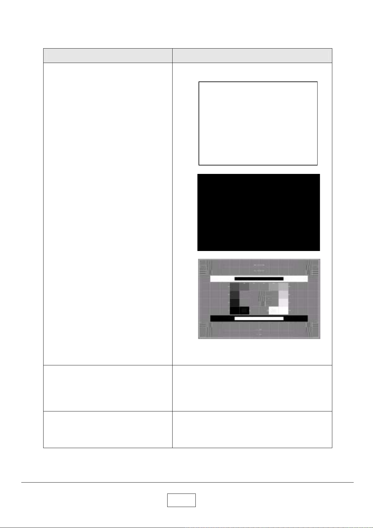
Test Verification
DMD Images
SINGOWS2000
White image (Level 100%)
SINGOWS2000
Black image (Level 0%)
Verify that each image synchronizes properly through the computer
1 input.
SINGOWS2000
SMPTE image
System Reset
On the keypad, press the Menu key.
Navigate through the basic menu to the default
setting menu.
Select Reset all.
Power Down
After all tests are complete turn the power off
and disconnect all cables.
Attach the lens cap.
Verify there are no problems
Verify that the image synchronizes after system reset.
Verify unit is powered off before disconnecting cables.
8-4
Page 79
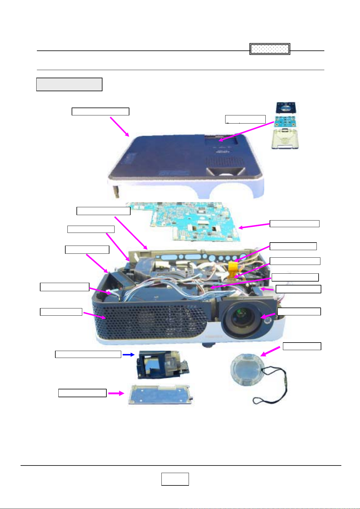
Chapter 9
A
A
A
Spare Parts List
Exploded View
100:Assy Cover Top
B110:Panel Rear
Chapter 9
U006:KEY
B131:Cover Ballast
Z105:Exhaust
P801:Main Power
B111:Panel
Lamp (Not Service parts)
210:Cover Lamp
U001:PCB FXMA2
P800:Filter Power
Z200:Optical Engine
Z101:Panel FAN A
Z100:Panel FAN
B100:Cover BTM
220:Lens
9-1
Page 80
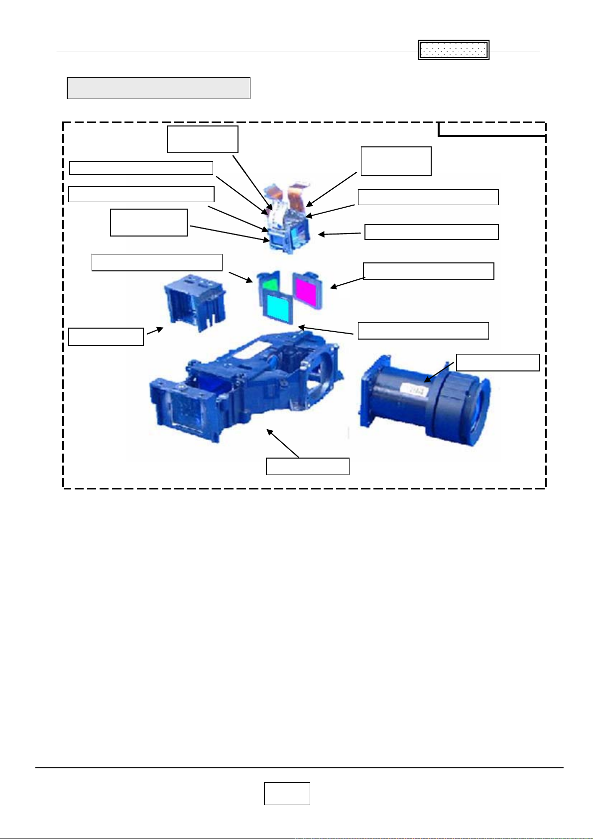
Chapter
㧥
Exploded View(Optics Block)
G001/G002
G001/G002
LCD PANEL
LCD PANEL
Z202G:POLARYZER OUT-G
E202G:POLARYZER OUT-G
Z202B:POLARYZER OUT-B
E202B:POLARYZER OUT-B
B001/B002
B001/B002
LCD PANEL
LCD PANEL
Z201G:POLARYZER IN-G
E201G:POLARYZER IN-G
Z203:591PBS
E203:591PBS
E100:OPTICS BLOCK
R001/R002
R001/R002
LCD PANEL
LCD PANEL
Z202R:POLARYZER OUT-R
E202R:POLARYZER OUT-R
Z200:PRISM BLOCK
PRISM BLOCK (not service)
Z201R:POLARYZER IN-R
E201R:POLARYZER IN-R
Z201B:POLARYZER IN-B
E201B:POLARYZER IN-B
Z205:591LENS
E205:591LENS
E200:SUB ASSY
9-2
Page 81
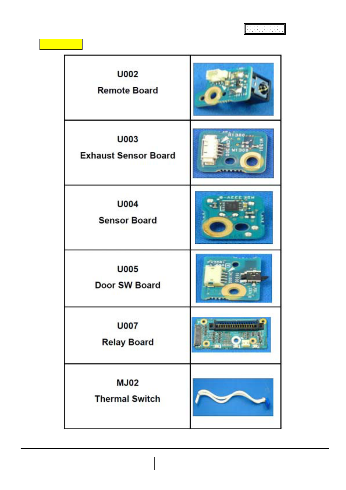
㸷
Other Parts
Chapter
9-3
Page 82
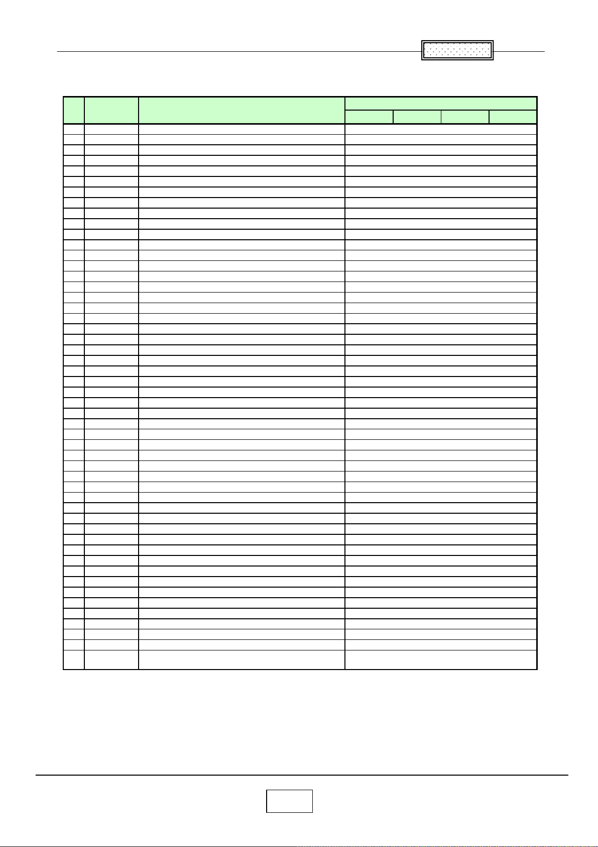
Chapter
㧥
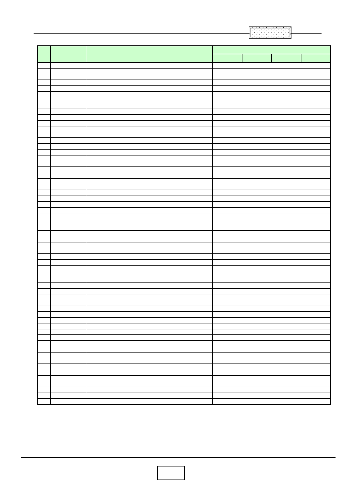
Spare parts list (TLP-X2000) GREEN
No Location Description
1 A100 COVER ASSY, TOP
2 A101 SCREW, 2.0 X 4.0 MM
3 A102A SCREW
4 A110 CASE ASSY, CONTROL UP
5 A110A SCREW, 2.0 X 4.0 MM
6 A111 CASE ASSY, CONT LOWER
7 A111A SCREW, 2.0 X 4.0 MM
8 A210 COVER ASSY, LAMP
9 A220 CAP, LENS
10 A230 COVER ASSY, FILTER BOTTOM
11 A304 LABEL, CAUTION
12 A305 LABEL, CAUTION HOT BLACK
13 A306 LABEL, LABEL CAUTION, LENS BLACK
14 A307 LABEL, CARTON,TLP-X2000
15 A308 LABEL, TOP TAG
16 A310 LABEL, CASE LOWER, X2000
17 A401 CARTON BOX, X2000
18 A401B SHEET, PROTECTIVE 700X300
19 A405 SOFT CASE, X2000
20 B001 LCD PANEL, L3P06X-56G20B
21 B002 LCD PANEL, L3P06X-55G20B
22 B100 COVER ASSY, BOTTOM
23 B101 SCREW
24 B111 PANEL, FRONT
25 B112 PANEL, SIDE
26 B113 PANEL ASSY, LENS
27 B120 PLATE, AC-IN
28 B131 COVER, LAMP
29 B141 AIR DUCT, POWER FAN
30 B170 AIR DUCT
31 CN105 CONNECTOR, 1.25MM PITCH W TO B
32 CN108 CONNECTOR, 1.25MM PITCH W TO B
33 CN503 CONNECTOR, D-SUB, DZ11A92-ND201-7F
34 E100 OPTICS BLOCK, CJ591TA
35 E200 OPTICS BLOCK, 591SUB
36 E201B OPTICS BLOCK, 591IN-B
37 E201G OPTICS BLOCK, 591IN-G
38 E201R OPTICS BLOCK, 591IN-R
39 E202B OPTICS BLOCK, 591OUT-B
40 E202G OPTICS BLOCK, 591OUT-G
41 E202R OPTICS BLOCK, 591OUT-R
42 E203 LENS, 591PBS
43 E205 LENS, 591LENS
44 E209 SERVICE KIT, X2000 LCD SRVICE KIT
45 E255 LENS, ANLC03T
46 E270 HOLDER ASSY, LAMP
47 G001 LCD PANEL, L3P06X-55G20G
48 G002 LCD PANEL, L3P06X-56G20G
49 IC100 IC, PW 190-10L, IMAGE PROCESSOR
50 IC101 IC, BD87A29FVM-TR, VOLTAGE DETECTOR
51 IC104
IC, PQ1MX55M2SPQ, LOW VOLTAGE
REGULATOR
EBUCH
Part No
75004216
70391261
23738144
75004217
70391261
75004218
70391261
75004221
75004222
75004223
75004197
75004198
75004200
75004195
75004196
75004201
75004232
75004234
75004233
75004158
75004155
75004219
23738144
75004225
75004226
75004227
75004230
75004220
75004229
75004228
75002110
75002110
75004141
75004205
75004207
75004210
75004209
75004208
75004213
75004212
75004211
75004214
75004206
75013210
75004215
75004231
75004154
75004157
75004414
75004425
75004417
9-4
Page 83
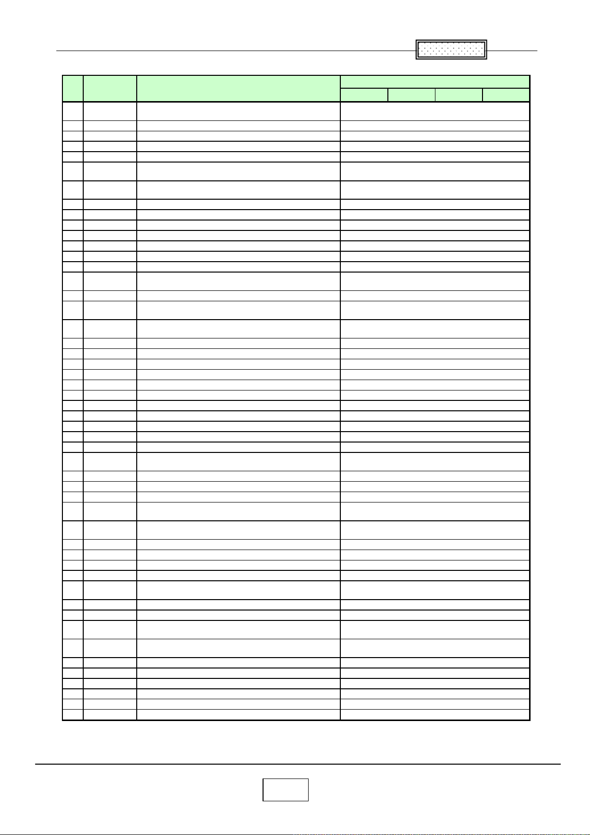
Chapter
㧥
No Location Description
52 IC105
53 IC108 IC, 24LC128T-I/SNG
54 IC1100 IC, PNA4612M01TH, PD WITH REMOTE CONT
55 IC111 IC, TC7SH08FU(TE85L,F)
56 IC112 IC, L3232ECV-16Z-T
57 IC119
58 IC1200
59 IC122 IC, TC7SH08FU(TE85L,F)
60 IC123 IC, TC7SH08FU(TE85L,F)
61 IC124 IC, SN74AHCT1G08DCKR, 2 INPUT AND GATE
62 IC125 IC, SN74AHCT1G08DCKR, 2 INPUT AND GATE
63 IC126 IC, BD4843G-TR, VOLTAGE DETECTOR
64 IC127 IC, TC7SH08FU(TE85L,F)
65 IC129 IC, TC7SH08FU(TE85L,F)
66 IC1300
67 IC350 IC, TC7WBD126AFK(T5L,F, DUAL BUS SWITCH
68 IC351
69 IC352
70 IC353 IC, PQ200WNA1ZPH, VOLTAGE REGULATOR
71 IC354 IC, PQ200WNA1ZPH, VOLTAGE REGULATOR
72 IC355 IC, PQ200WNA1ZPH, VOLTAGE REGULATOR
73 IC356 IC, PQ200WNA1ZPH, VOLTAGE REGULATOR
74 IC357 IC, PQ200WNA1ZPH, VOLTAGE REGULATOR
75 IC358 IC, M62334FP DF5J, D/A CONVERTER
76 IC359 IC, PQ200WNA1ZPH, VOLTAGE REGULATOR
77 IC501 IC, XC95144XL-10TQG100C-X2000
78 IC502 IC, MXD2020EL-T/R, ACCELEROMETER
79 IC503 IC, MAX4885ETJ+TG40, ANALOG SWITCH
80 IC504 IC, EL4340IUZ-T7, MULTIPLEXING AMPLIFIER
81 IC505
82 IC506 IC, EL4332CSZ-T7, VIDEO MULTIPLEXING
83 IC507 IC, EL5106IW Z-T7, GAIN AMPLIFIER
84 IC508 IC, EL5106IW Z-T7, GAIN AMPLIFIER
85 IC509
86 IC510
87 IC511 IC, ISL59885ISZ-T7, VIDEO SYNC SEPARATOR
88 IC512 IC, ISL59885ISZ-T7, VIDEO SYNC SEPARATOR
89 IC513 IC, BU9882FV-WE2, 2KBIT EEPROM
90 IC514 IC, MM1565AFBE, VOLTAGE REGULATOR
91 IC515
92 IC6001 IC, NJM2370U1-09-TE1, VOLTAGE REGULATOR
93 IC6002 IC, NJM2370U1-09-TE1, VOLTAGE REGULATOR
94 IC6003
95 IC6004
96 IC6005 IC, NJW1142AV(TE1), AUDIO PROCESSOR
97 IC6010 IC, EL1883ISZ-T7, SYNC SEPARATOR
98 IC6011 IC, EL1883ISZ-T7, SYNC SEPARATOR
99 IC6012 IC, TC7SH08FU(TE85L,F)
100 IC6021 IC, TC7SH08FU(TE85L,F)
101 IC701 IC, PQ20VZ1UJ00H, LOW VOLTAGE REGULATOR
IC, TK11150CSCL-G, POSITIVE LDO
REGULATOR
IC, LTC3701EGN#TRPBF, DC/DC
CONTROLLER
IC, G751-2RDF, TEMPERATURE SENSOR AND
THERMAL WATCHDOG
IC, G751-2RDF, TEMPERATURE SENSOR AND
THERMAL WATCHDOG
IC, G768BF, TEMPERATURE SENSOR AND
FAN CONTROLLER
IC, G794D5U, TEMPERATURE SENSOR AND
4FAN CONTROLLER
IC, SN74LVC2G17DCKR, DUAL SCHMITT-TRIGGER
BUFFER
IC, SN74LVC2G17DCKR, DUAL SCHMITT-TRIGGER
BUFFER
IC, SN74LVC2G17DCKR, DUAL
SCHMITT-TRIGGER BUFFER
IC, LM2660MM, SWITCHED CAPACITOR
VOLTAGE CON
IC, NJM2886DL3-05(TE1), LOW DROPOUT
VOLTAGE REGULATOR
IC, TPA2005D1DGNRG4, AUDIO POWER
AMPLIFIER
Part No
EBUCH
75004418
75004412
75001241
75001245
75004413
75004148
75004147
75001245
75001245
75004410
75004410
75004150
75001245
75001245
75004147
75001220
75004146
75004421
75004422
75004422
75004422
75004422
75004422
75001226
75004422
75004143
75004419
75004151
75004429
75004411
75001323
75004430
75004430
75004411
75004411
75004424
75004424
75004415
75004420
75001237
75001239
75001239
75004427
75004428
75004426
75004423
75004423
75001245
75001245
75004416
9-5
Page 84
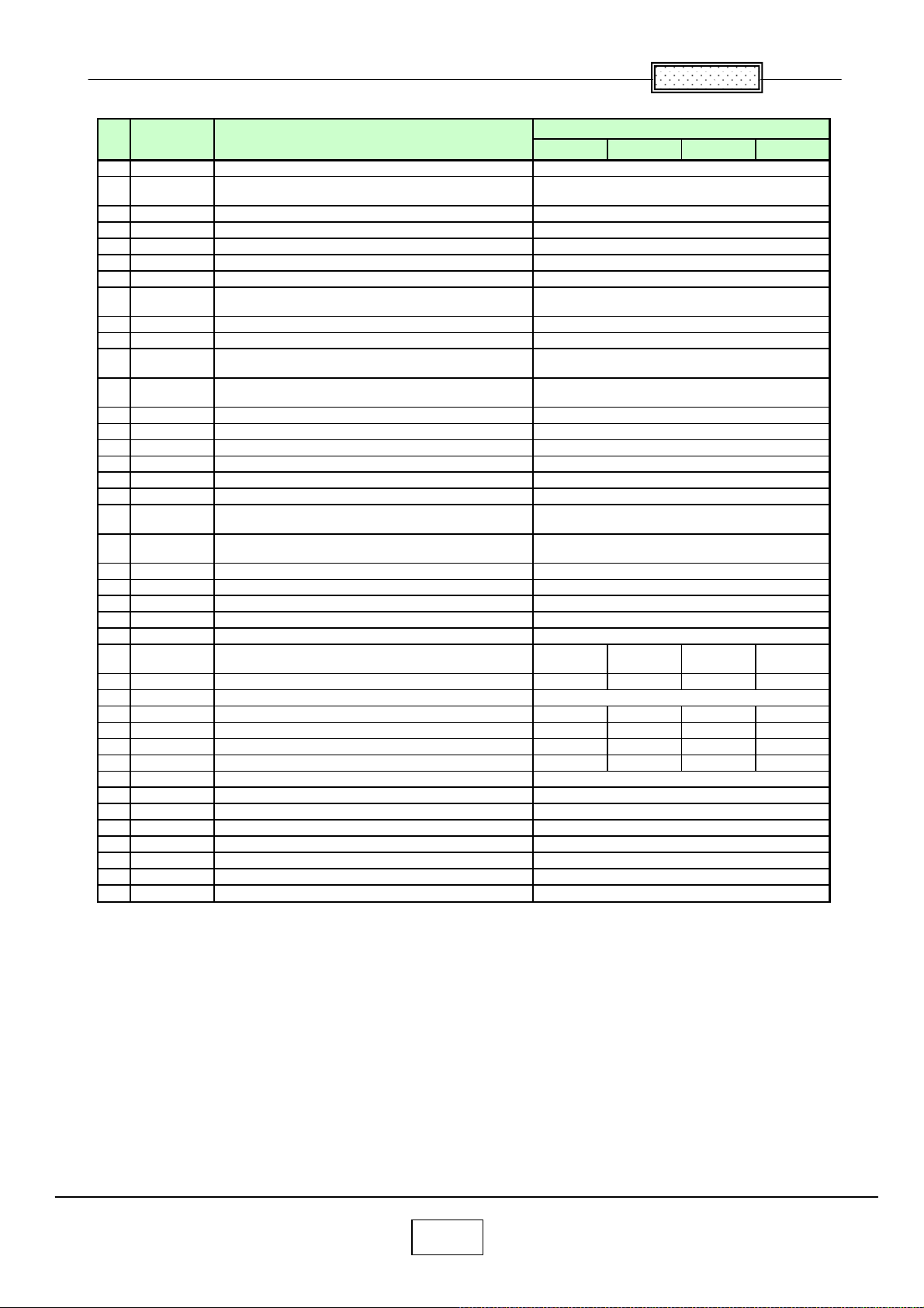
Chapter
㧥
No Location Description
102 IC702 IC, TC7SH08FU(TE85L,F)
103 IC703
104 IC704 IC, L3E07072K0A, TFT-LCD CONTROLLER
105 IC801 IC, L3E06100D0B, TFT-LCD CONTROLLER
106 IC831 IC, L3E06100D0B, TFT-LCD CONTROLLER
107 IC861 IC, L3E06100D0B, TFT-LCD CONTROLLER
108 J6001 CONNECTOR, LAP5300-0110F
109 MJ02
110 P800 PC BOARD ASSY, LINE-FILTER, APS-T602
111 P801 PC BOARD ASSY, MAIN POWER, APS-T603
112 P850
113 Q101
114 R001 LCD PANEL, L3P06X-56G20R
115 R002 LCD PANEL, L3P06X-55G20R
116 S1605 SWITCH, TACT, TSW -6A-1-16-T50
117 S501 SWITCH, SLIDE, SLD-12-500
118 SP200 SPEAKER, RFF-0401C-02
119 U001 PC BOARD ASSY, MAIN, FX2MA2
120 U002
121 U003
122 U004 PC BOARD ASSY, SENSOR, FX2SE2
123 U005 PC BOARD ASSY, DOOR SWITCH, FX2DR2
124 U006 PC BOARD ASSY, KEY, FX2KY2
125 U007 PC BOARD ASSY, RELAY BOARD, FX2RL2
126 Y100 CABLE, RGB, BLUE
127 Y200
128 Y200 OWNER'S MANUAL, TLP-X2000C ----- ----- ----- 75004975
129 Y201 CD-ROM, OWNERS MANUAL, X2000 SIRIES
130 Y260 POWER CORD, CEE 250V 6A, 3M 23372167 ----- ----- ----131 Y260 POWER CORD, UL 125V 10A, 3M ----- ----- 23372148 ----132 Y260 POWER CORD, GB250V10A ----- ----- ----- 23372155
133 Y260 POWER CORD, UK250V6A ----- 23372337 ----- ----134 Y700 REMOCON HAND UNIT, CT-90264
135 Y702 REMOCON RECIVER, IR, MOUS, CR-916
136 Z100 FAN, TYF450FJ06
137 Z101 FAN, TYF400FJ10
138 Z102 FAN, D05F-12BS2 02A
139 Z103 FAN, TYF310FJ11
140 Z104 FAN, D05F-12PS7 01A(EX)
141 Z105 FAN, D07R-12TH 03A(EX)
IC, BA10324AFV-E2,QUAD OPERATIONAL
AMPLIFIER
SWITCH, THERMAL SWITCH W HITH W IRE
HARNESS
PC BOARD ASSY, LAMP POWER,
PS-240A-MS-120-22H
TRANSISTOR, UM6K1NTN, N-CH MOS FET
MODULE
PC BOARD ASSY, REMOCON RECEIVER,
FX2RE2
PC BOARD ASSY, EXHAUST SENSOR,
FX2EX2
OWNERS MANUAL ASSY, X2000, MULTI
LANGUAGE
EBUCH
75004235 75004235 75004235 -----
Part No
75001245
75004149
75004145
75004144
75004144
75004144
75004140
75005121
23122519
23122520
75004203
75004142
75004156
75004153
75004139
75004138
23351359
75004132
75004133
75004134
75004135
75004136
75004137
75004131
23368955
75004236
75004204
23306621
75004190
75004160
23125960
75004159
75004191
75004192
9-6
Page 85
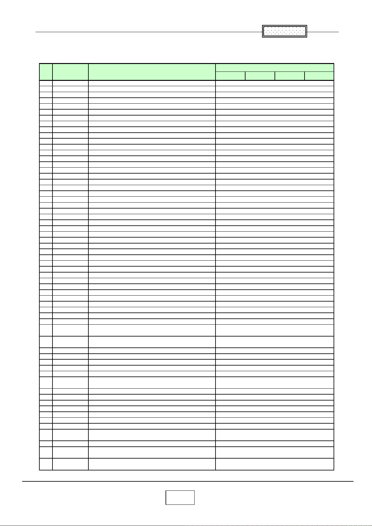
Chapter
㧥
A
(
)
(
)
(
)
(
)
(
)
(
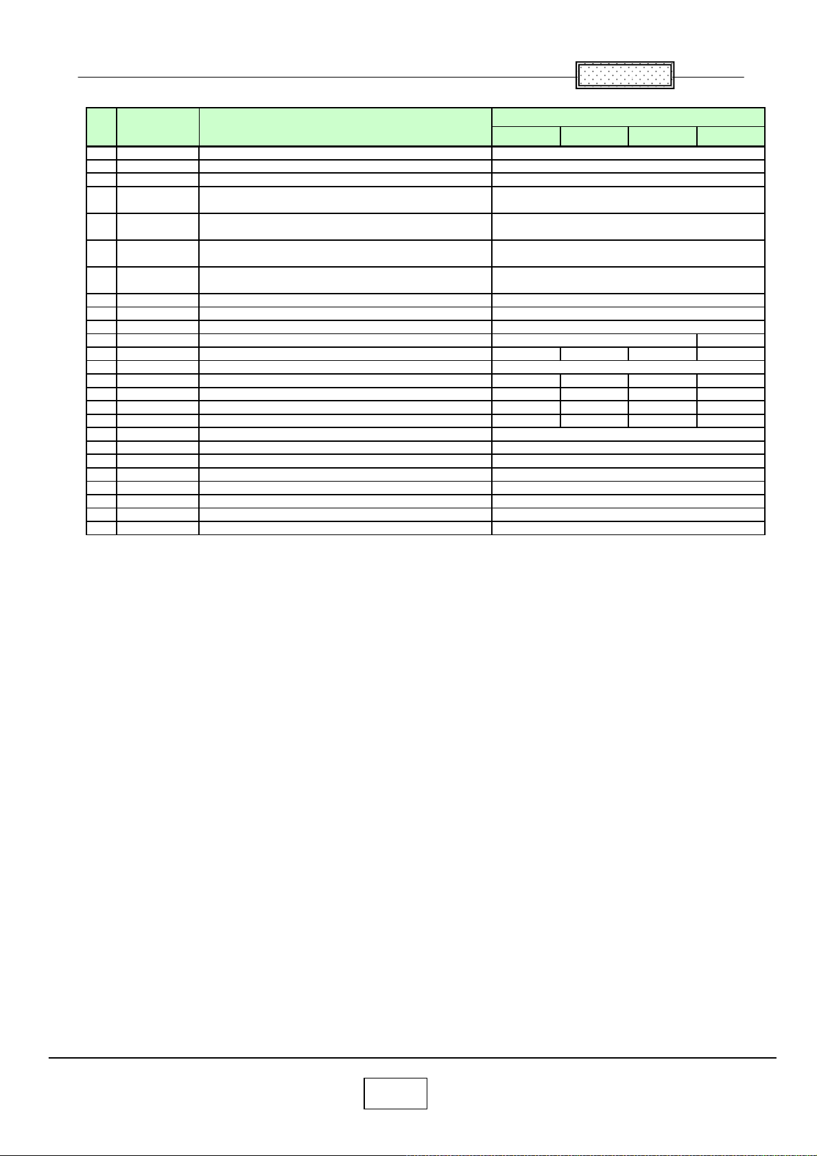
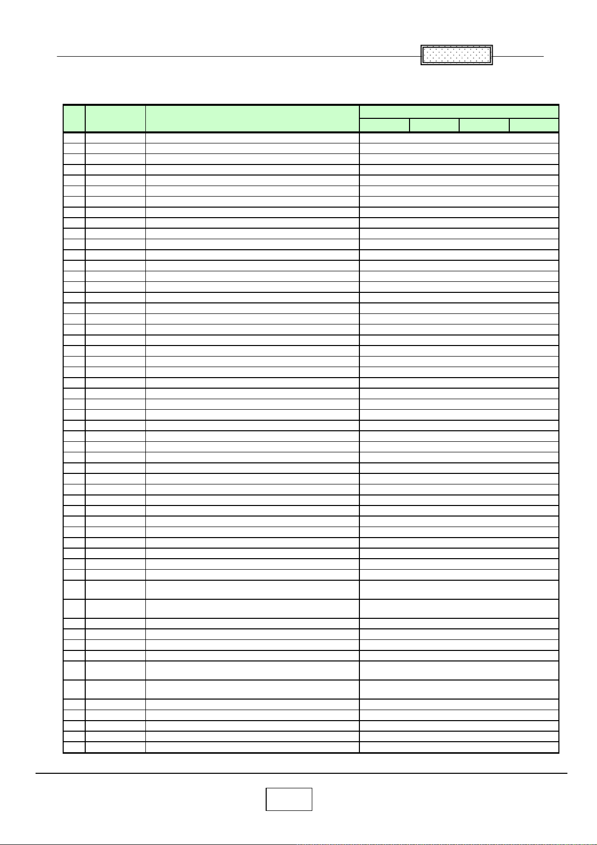
Spare parts list (TLP-X2500) GREEN
No Location Description
1 A100
2 A101
3 A102A
4 A110
5 A110A
6 A111
7 A111A
8 A210
9 A220
10 A230
11 A401
12 A405
13 B001
14 B002
15 B100
16 B111
17 B112
18 B113
19 B120
20 B131
21 B141
22 B170
23 CN105
24 CN108
25 CN503
26 E100
27 E200
28 E201B
29 E201G
30 E201R
31 E202B
32 E202G
33 E202R
34 E203
35 E205
36 E209
37 E255
38 E270
39 G001
40 G002
41 IC100
42 IC101
43 IC104
44 IC105
45 IC107
46 IC1100
47 IC111
48 IC112
49 IC119
50 IC1200
51 IC122
52 IC123
53 IC124
54 IC125
55 IC126
56 IC127
57 IC129
58 IC1300
59 IC350
60 IC351
61 IC352
COVER ASSY, TOP
SCREW, 2.0 X 4.0 MM
SCREW
CASE ASSY, CONTROL UP
SCREW, 2.0 X 4.0 MM
CASE ASSY, CONT LOWER
SCREW, 2.0 X 4.0 MM
COVER ASSY, LAMP
CAP, LENS
COVER ASSY, FILTER BOTTOM
CARTON BOX, X2000
SOFT CASE, X2000
LCD PANEL, L3P06X-66G00B
LCD PANEL, L3P06X-65G00B
COVER ASSY, BOTTOM
PANEL, FRONT
PANEL, SIDE
PANEL ASSY, LENS
PLATE, AC-IN
COVER, LAMP
AIR DUCT, POWER FAN
AIR DUCT
CONNECTOR, 1.25MM PITCH W TO B
CONNECTOR, 1.25MM PITCH W TO B
CONNECTOR, D-SUB, DZ11A92-ND201-7F
OPTICAL BLOCK, ENGINE, CJ590T
OPTICAL BLOCK, SUB ASSY, 590SUB
POLARIZER, 591IN-B
POLARIZER, 591IN-G
POLARIZER, 591IN-R
POLARIZER, 591OUT-B
POLARIZER, 591OUT-G
POLARIZER, 591OUT-R
LENS, 591PBS
LENS, 591LENS
SERVICE KIT, X2000 LCD SRVICE KIT
LENS, ANLC03T
HOLDER ASSY, LAMP
LCD PANEL, L3P06X-65G00G
LCD PANEL, L3P06X-66G00G
IC, PW190-10L, IMAGE PROCESSOR
IC, BD87A29FVM-TR, VOLTAGE DETECTOR
IC, PQ1MX55M2SPQ, LOW VOLTAGE
REGULATOR
IC, TK11150CSCL-G, POSITIVE LDO
REGULATOR
IC, ES29LV160ET-70TGI
IC, PNA4612M01TH, PD WITH REMOTE CONT
IC, TC7SH08FU
IC, L3232ECV-16Z-T
IC, LTC3701EGN#TRPBF, DC/DC CONTROLLER
IC, G751-2RDF, TEMPERATURE SENSOR AND
THERMAL WATCHDOG
IC, TC7SH08FU
IC, TC7SH08FU
IC, SN74AHCT1G08DCKR, 2 INPUT AND GATE
IC, SN74AHCT1G08DCKR, 2 INPUT AND GATE
IC, BD4843G-TR, VOLTAGE DETECTOR
IC, TC7SH08FU
IC, TC7SH08FU
IC, G751-2RDF, TEMPERATURE SENSOR AND
THERMAL WATCHDOG
IC, TC7WBD126AFK
IC, G768BF, TEMPERATURE SENSOR AND
FAN CONTROLLER
IC, G794D5U, TEMPERATURE SENSOR AND
4FAN CONTROLLER
TE85L,F
TE85L,F
TE85L,F
TE85L,F
TE85L,F
T5L,F, DUAL BUS SWITCH
EBUCH
Part No
75004216
70391261
23738144
75004217
70391261
75004218
70391261
75004221
75004222
75004223
75004232
75004233
75004771
75004767
75004219
75004225
75004226
75004227
75004230
75004220
75004229
75004228
75002110
75002110
75004141
75004775
75004776
75004210
75004209
75004208
75004213
75004212
75004211
75004214
75004206
75013210
75004215
75004231
75004766
75004769
75004414
75004425
75004417
75004418
75004763
75001241
75001245
75004413
75004148
75004147
75001245
75001245
75004410
75004410
75004150
75001245
75001245
75004147
75001220
75004146
75004421
9-7
Page 86
Chapter
㧥
(
(
)
(
)
(
)
No Location Description
62 IC353
63 IC354
64 IC355
65 IC356
66 IC357
67 IC358
68 IC359
69 IC501
70 IC502
71 IC503
72 IC504
73 IC505
74 IC506
75 IC507
76 IC508
77 IC509
78 IC510
79 IC511
80 IC512
81 IC513
82 IC514
83 IC515
84 IC6001
85 IC6002
86 IC6003
87 IC6004
88 IC6005
89 IC6010
90 IC6011
91 IC6012
92 IC6021
93 IC701
94 IC702
95 IC703
96 IC704
97 IC801
98 IC802
99 IC831
100 IC832
101 IC861
102 IC862
103 J6001
104 MJ02
105 P800
106 P801
107 P850
108 Q101
109 R001
110 R002
111 S1605
IC, PQ200WNA1ZPH, VOLTAGE REGULATOR
IC, PQ200WNA1ZPH, VOLTAGE REGULATOR
IC, PQ200WNA1ZPH, VOLTAGE REGULATOR
IC, PQ200WNA1ZPH, VOLTAGE REGULATOR
IC, PQ200WNA1ZPH, VOLTAGE REGULATOR
IC, M62334FP DF5J, D/A CONVERTER
IC, PQ200WNA1ZPH, VOLTAGE REGULATOR
IC, XC95144XL-10TQG100C-X2000
IC, MXD2020EL-T/R, ACCELEROMETER
IC, MAX4885ETJ+TG40, ANALOG SWITCH
IC, EL4340IUZ-T7, MULTIPLEXING AMPLIFIER
IC, SN74LVC2G17DCKR, DUAL SCHMITT-TRIGGER
BUFFER
IC, EL4332CSZ-T7, VIDEO MULTIPLEXING
IC, EL5106IWZ-T7, GAIN AMPLIFIER
IC, EL5106IWZ-T7, GAIN AMPLIFIER
IC, SN74LVC2G17DCKR, DUAL SCHMITT-TRIGGER
BUFFER
IC, SN74LVC2G17DCKR, DUAL SCHMITT-TRIGGER
BUFFER
IC, ISL59885ISZ-T7, VIDEO SYNC SEPARATOR
IC, ISL59885ISZ-T7, VIDEO SYNC SEPARATOR
IC, BU9882FV-WE2, 2KBIT EEPROM
IC, MM1565AFBE, VOLTAGE REGULATOR
IC, LM2660MM, SWITCHED CAPACITOR VOLTAGE
IC, NJM2370U1-09-TE1, VOLTAGE REGULATOR
IC, NJM2370U1-09-TE1, VOLTAGE REGULATOR
IC, NJM2886DL3-05(TE1), LOW DROPOUT
VOLTAGE REGULATOR
IC, TPA2005D1DGNRG4, AUDIO POWER
AMPLIFIER
IC, NJW1142AV
IC, EL1883ISZ-T7, SYNC SEPARATOR
IC, EL1883ISZ-T7, SYNC SEPARATOR
IC, TC7SH08FU
IC, TC7SH08FU
IC, PQ20VZ1UJ00H, LOW VOLTAGE
REGULATOR
IC, R1172H121D-T1-F, VOLTAGE REGULATOR
IC, TC7SH08FU
IC, L3E07110K0A,TIMING PULSE GENERATOR
IC, L3E06150S2A,TFT-LCD CONTROLLER
IC, L3E01060P0A
IC, L3E06150S2A,TFT-LCD CONTROLLER
IC, L3E01060P0A
IC, L3E06150S2A,TFT-LCD CONTROLLER
IC, L3E01060P0A
CONNECTOR, LAP5300-0110F
SWITCH, THERMAL SWITCH WITH WIRE
HARNESS
PC BOARD ASSY, LINE-FILTER, APS-T602
PC BOARD ASSY, MAIN POWER, APS-T603
PC BOARD ASSY, LAMP POWER,
PS-240A-MS-120-22H
TRANSISTOR, UM6K1NTN, N-CH MOS FET
MODULE
LCD PANEL, L3P06X-66G00R
LCD PANEL, L3P06X-65G00R
SWITCH, TACT, TSW-6A-1-16-T50
TE1), AUDIO PROCESSOR
TE85L,F
TE85L,F
TE85L,F
Part No
EBUCH
75004422
75004422
75004422
75004422
75004422
75001226
75004422
75004143
75004419
75004151
75004429
75004411
75001323
75004430
75004430
75004411
75004411
75004424
75004424
75004415
75004420
75001237
75001239
75001239
75004427
75004428
75004426
75004423
75004423
75001245
75001245
75004416
75004762
75001245
75004760
75004761
75004759
75004761
75004759
75004761
75004759
75004140
75005121
23122519
23122520
75004203
75004142
75004768
75004764
75004139
9-8
Page 87
Chapter
㧥
A
A
A
(EX)
(EX)
No Location Description
112 S501
113 SP200
114 U001
115 U002
116 U003
117 U004
118 U005
119 U006
120 U007
121 Y100
122 Y200
123 Y200
124 Y205
125 Y260
126 Y260
127 Y260
128 Y260
129 Y700
130 Y702
131 Z100
132 Z101
133 Z102
134 Z103
135 Z104
136 Z105
SWITCH, SLIDE, SLD-12-500
SPEAKER, RFF-0401C-02
PC BOARD ASSY, MAIN, FX5MA2, TLP-X2500
PC BOARD ASSY, REMOCON, FX5RE2,
TLP-X2500
PC BOARD ASSY, EXTERNAL, FX5EX2,
TLP-X2500
PC BOARD ASSY, SENSOR, FX5SE2,
TLP-X2500
PC BOARD ASSY, DOOR SWITCH, FX5DR2,
TLP-X2500
PC BOARD ASSY, KEY, FX5KY2, TLP-X2500
PC BOARD ASSY, FX2RL2
CABLE, RGB, BLUE
OWNERS MANUAL, X2500U/E/B/J
OWNERS MANUAL, X2500C
OWNER'S MANUAL, X2000SERIES ERRAT
POWER CORD, CEE250V6A 3M
POWER CORD, UL125V10A 3M
POWER CORD SET, UK250V6
POWER CORD, GB250V10A
REMOCON HAND UNIT, CT-90266
REMOCON RECIVER, IR, MOUS, CR-916
FAN, TYF450FJ06
FAN, TYF400FJ10
FAN, D05F-12BS2 02
FAN, TYF310FJ11
FAN, D05F-12PS7 01A
FAN, D07R-12TH 03A
Part No
EBUCH
75004138
23351359
75004673
75004674
75004675
75004676
75004677
75004678
75004131
23368955
75004777
----- ----- ----- 75005669
75004435
23372167 ----- ----- -----
----- ----- 23372148 -----
----- 23372337 ----- -----
----- ----- ----- 23372155
75004774
23306621
75004190
75004160
23125960
75004159
75004191
75004192
-----
9-9
Page 88
Chapter
㧥
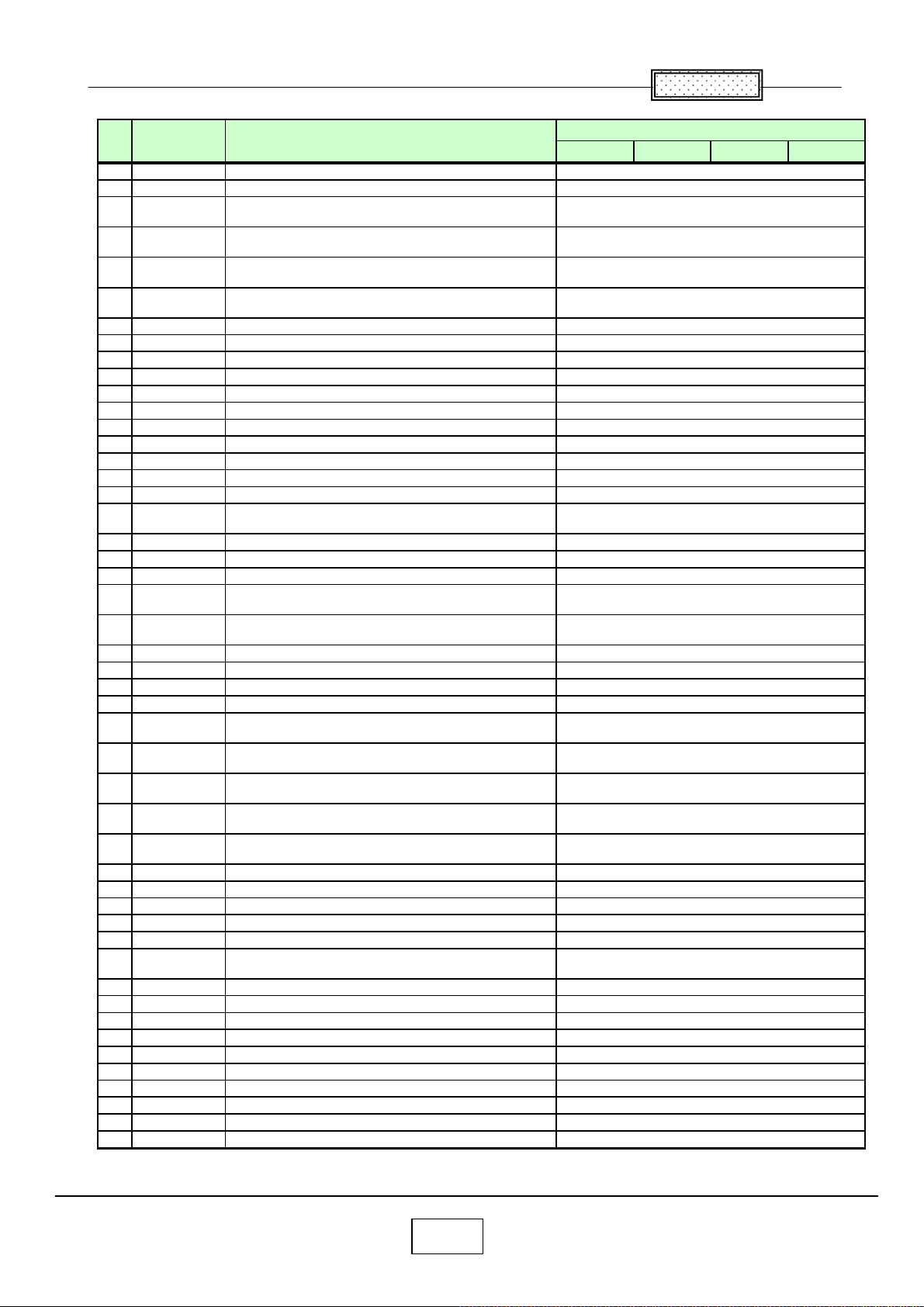
Spare parts list (TLP-X3000) GREEN
No Location Description
1 A100 COVER ASSY, TOP
2 A101 SCREW, 2.0 X 4.0 MM
3 A102A SCREW
4 A110 CASE ASSY, CONTROL UP
5 A110A SCREW, 2.0 X 4.0 MM
6 A111 CASE ASSY, CONT LOWER
7 A111A SCREW, 2.0 X 4.0 MM
8 A210 COVER ASSY, LAMP
9 A220 LENS CAP, 07 MDN
10 A230 COVER ASSY, FILTER BOTTOM
11 A301 LABEL, RATING, X3000
12 A401 CARTON BOX, X2000
13 A405 SOFT CASE, X2000
14 A502 LABEL
15 B001 LCD PANEL, L3P07X-66G00B
16 B002 LCD PANEL, L3P07X-65G00B
17 B100 COVER ASSY, BOTTOM
18 B111 PANEL, FRONT
19 B112 PANEL, SIDE
20 B113 PANEL ASSY, LENS
21 B120 PLATE, AC-IN
22 B131 COVER, LAMP
23 B141 AIR DUCT, POWER FAN
24 B170 AIR DUCT
25 CN105 CONNECTOR, 1.25MM PITCH W TO B
26 CN108 CONNECTOR, 1.25MM PITCH W TO B
27 CN503 CONNECTOR, D-SUB, DZ11A92-ND201-7F
28 E100 OPTICAL BLOCK, CJ589TA
29 E200 OPTICAL BLOCK, SUB ASSY, 589SUB
30 E201B POLARIZER, 591IN-B
31 E201G POLARIZER, 591IN-G
32 E201R POLARIZER, 591IN-R
33 E202B OPTICAL FILTER, 589OUT-B
34 E202G OPTICAL FILTER, 589OUT-G
35 E202R OPTICAL FILTER, 589OUT-R
36 E205 LENS, 589LENS
37 E209 SERVICE KIT, X3000 LCD SERVICE KIT
38 E270 HOLDER ASSY, LAMP
39 G001 LCD PANEL, L3P07X-65G00G
40 G002 LCD PANEL, L3P07X-66G00G
41 IC100 IC, PW190-10L, IMAGE PROCESSOR
42 IC101 IC, BD87A29FVM-TR, VOLTAGE DETECTOR
43 IC104
44 IC105
45 IC107 IC, ES29LV160ET-70TGI
46 IC1100 IC, PNA4612M01TH, PD WITH REMOTE CONT
47 IC111 IC, TC7SH08FU(TE85L,F)
48 IC112 IC, L3232ECV-16Z-T
49 IC119
50 IC1200
51 IC122 IC, TC7SH08FU(TE85L,F)
52 IC123 IC, TC7SH08FU(TE85L,F)
53 IC124 IC, SN74AHCT1G08DCKR, 2 INPUT AND GATE
54 IC125 IC, SN74AHCT1G08DCKR, 2 INPUT AND GATE
55 IC126 IC, BD4843G-TR, VOLTAGE DETECTOR
IC, PQ1MX55M2SPQ, LOW VOLTAGE
REGULATOR
IC, TK11150CSCL-G, POSITIVE LDO
REGULATOR
IC, LTC3701EGN#TRPBF, DC/DC
CONTROLLER
IC, G751-2RDF, TEMPERATURE SENSOR AND
THERMAL WATCHDOG
EBUCH
Part No
75004216
70391261
23738144
75004217
70391261
75004218
70391261
75004221
75005367
75004223
75005357
75004232
75004233
23564859
75005356
75005353
75004219
75004225
75004226
75004227
75004230
75004220
75004229
75004228
75002110
75002110
75004141
75005360
75005362
75004210
75004209
75004208
75005365
75005364
75005363
75005361
75013211
75004231
75005352
75005355
75004414
75004425
75004417
75004418
75004763
75001241
75001245
75004413
75004148
75004147
75001245
75001245
75004410
75004410
75004150
9-10
Page 89
Chapter
㧥
No Location Description
56 IC127 IC, TC7SH08FU(TE85L,F)
57 IC129 IC, TC7SH08FU(TE85L,F)
58 IC1300
59 IC350
60 IC351
61 IC352
62 IC353 IC, PQ200WNA1ZPH, VOLTAGE REGULATOR
63 IC354 IC, PQ200WNA1ZPH, VOLTAGE REGULATOR
64 IC355 IC, PQ200WNA1ZPH, VOLTAGE REGULATOR
65 IC356 IC, PQ200WNA1ZPH, VOLTAGE REGULATOR
66 IC357 IC, PQ200WNA1ZPH, VOLTAGE REGULATOR
67 IC358 IC, M62334FP DF5J, D/A CONVERTER
68 IC359 IC, PQ200WNA1ZPH, VOLTAGE REGULATOR
69 IC501 IC, XC95144XL-10TQG100C-X2000
70 IC502 IC, MXD2020EL-T/R, ACCELEROMETER
71 IC503 IC, MAX4885ETJ+TG40, ANALOG SWITCH
72 IC504 IC, EL4340IUZ-T7, MULTIPLEXING AMPLIFIER
73 IC505
74 IC506 IC, EL4332CSZ-T7, VIDEO MULTIPLEXING
75 IC507 IC, EL5106IWZ-T7, GAIN AMPLIFIER
76 IC508 IC, EL5106IWZ-T7, GAIN AMPLIFIER
77 IC509
78 IC510
79 IC511 IC, ISL59885ISZ-T7, VIDEO SYNC SEPARATOR
80 IC512 IC, ISL59885ISZ-T7, VIDEO SYNC SEPARATOR
81 IC513 IC, BU9882FV-WE2, 2KBIT EEPROM
82 IC514 IC, MM1565AFBE, VOLTAGE REGULATOR
83 IC515
84 IC6001
85 IC6002
86 IC6003
87 IC6004
88 IC6005 IC, NJW1142AV(TE1), AUDIO PROCESSOR
89 IC6010 IC, EL1883ISZ-T7, SYNC SEPARATOR
90 IC6011 IC, EL1883ISZ-T7, SYNC SEPARATOR
91 IC6012 IC, TC7SH08FU(TE85L,F)
92 IC6021 IC, TC7SH08FU(TE85L,F)
93 IC701
94 IC702 IC, R1172H121D-T1-F, VOLTAGE REGULATOR
95 IC703 IC, TC7SH08FU(TE85L,F)
96 IC704 IC, L3E07110K0A,TIMING PULSE GENERATOR
97 IC801 IC, L3E06150S2A,TFT-LCD CONTROLLER
98 IC802 IC, L3E01060P0A
99 IC831 IC, L3E06150S2A,TFT-LCD CONTROLLER
100 IC832 IC, L3E01060P0A
101 IC861 IC, L3E06150S2A,TFT-LCD CONTROLLER
102 IC862 IC, L3E01060P0A
103 J6001 CONNECTOR, LAP5300-0110F
IC, G751-2RDF, TEMPERATURE SENSOR AND
THERMAL WATCHDOG
IC, TC7WBD126AFK(T5L,F, DUAL BUS
SWITCH
IC, G768BF, TEMPERATURE SENSOR AND
FAN CONTROLLER
IC, G794D5U, TEMPERATURE SENSOR AND
4FAN CONTROLLER
IC, SN74LVC2G17DCKR, DUAL SCHMITTTRIGGER BUFFER
IC, SN74LVC2G17DCKR, DUAL SCHMITTTRIGGER BUFFER
IC, SN74LVC2G17DCKR, DUAL SCHMITTTRIGGER BUFFER
IC, LM2660MM, SWITCHED CAPACITOR
VOLTAGE CON
IC, NJM2370U1-09-TE1, VOLTAGE
REGULATOR
IC, NJM2370U1-09-TE1, VOLTAGE
REGULATOR
IC, NJM2886DL3-05(TE1), LOW DROPOUT
VOLTAGE REGULATOR
IC, TPA2005D1DGNRG4, AUDIO POWER
AMPLIFIER
IC, PQ20VZ1UJ00H, LOW VOLTAGE
REGULATOR
Part No
EBUCH
75001245
75001245
75004147
75001220
75004146
75004421
75004422
75004422
75004422
75004422
75004422
75001226
75004422
75004143
75004419
75004151
75004429
75004411
75001323
75004430
75004430
75004411
75004411
75004424
75004424
75004415
75004420
75001237
75001239
75001239
75004427
75004428
75004426
75004423
75004423
75001245
75001245
75004416
75004762
75001245
75004760
75004761
75004759
75004761
75004759
75004761
75004759
75004140
9-11
Page 90
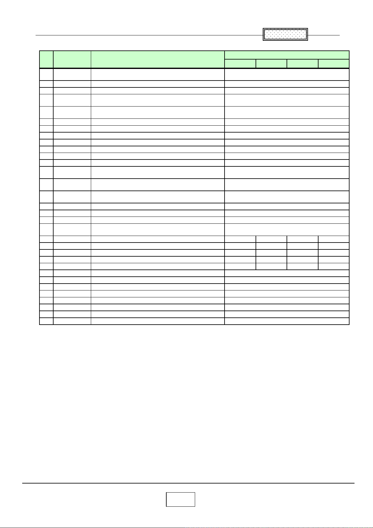
Chapter
㧥
,
No Location Description
104 MJ02
105 P800 PC BOARD ASSY, LINE-FILTER, APS-T602
106 P801 PC BOARD ASSY, MAIN POWER, APS-T603
107 P850
108 Q101
109 R001 LCD PANEL, L3P07X-66G00R
110 R002 LCD PANEL, L3P07X-65G00R
111 S1605 SWITCH, TACT, TSW -6A-1-16-T50
112 S501 SW ITCH, SLIDE, SLD-12-500
113 SP200 SPEAKER, RFF-0401C-02
114 U001 PC BOARD ASSY, MAIN, FX5MA2, TLP-X3000
115 U002 PC BOARD ASSY, RELAY, FX5RE2, TLP-X3000
116 U003
117 U004
118 U005
119 U006 PC BOARD ASSY, KEY, FX5KY2, TLP-X3000
120 U007 PC BOARD ASSY, RELAY, FX2RL2
121 Y100 CABLE, RGB, BLUE
122 Y200
123 Y200 OW NERS MANUAL, CHINESE, X3000C ----- ----- ----- 75005668
124 Y260 POWER CORD, UL 125V 10A, 3M ----- 23372148 ----125 Y260 POWER CORD, EU 23372167 ----- ----- ----126 Y260 POWER CORD, UK 23372337 ----- ----127 Y260 POWER CORD, CHINA ----- ----- ----- 23372155
128 Y700 REMOCON HAND UNIT, CT-90266
129 Y702 REMOCON RECIVER, IR, MOUS, CR-916
130 Z100 FAN, TYF450FJ06
131 Z101 FAN, TYF400FJ10
132 Z102 FAN, D05F-12BS2 02A
133 Z103 FAN, TYF310FJ11
134 Z104 FAN, D05F-12PS7 01A(EX)
135 Z105 FAN, D07R-12TH 03A(EX)
SWITCH, THERMAL SWITCH WITH WIRE
HARNESS
PC BOARD ASSY, LAMP POWER,
PS-240A-MS-120-22H
TRANSISTOR, UM6K1NTN, N-CH MOS FET
MODULE
PC BOARD ASSY, EXHAUST SENSOR,
FX5EX2
PC BOARD ASSY, SENSOR, FX5SE2,
TLP-X3000
PC BOARD ASSY, DOOR SWITCH, FX5DR2,
TLP-X3000
OWNERS MANUAL, CD-ROM AND BOOKLET,
X3000UEBJ
TLP-X3000
EBUCH
Part No
75005121
23122519
23122520
75004203
75004142
75005354
75005351
75004139
75004138
23351359
75005345
75005346
75005347
75005348
75005349
75005350
75004131
23368955
75005368
75004774
23306621
75004190
75004160
23125960
75004159
75004191
75004192
9-12
Page 91
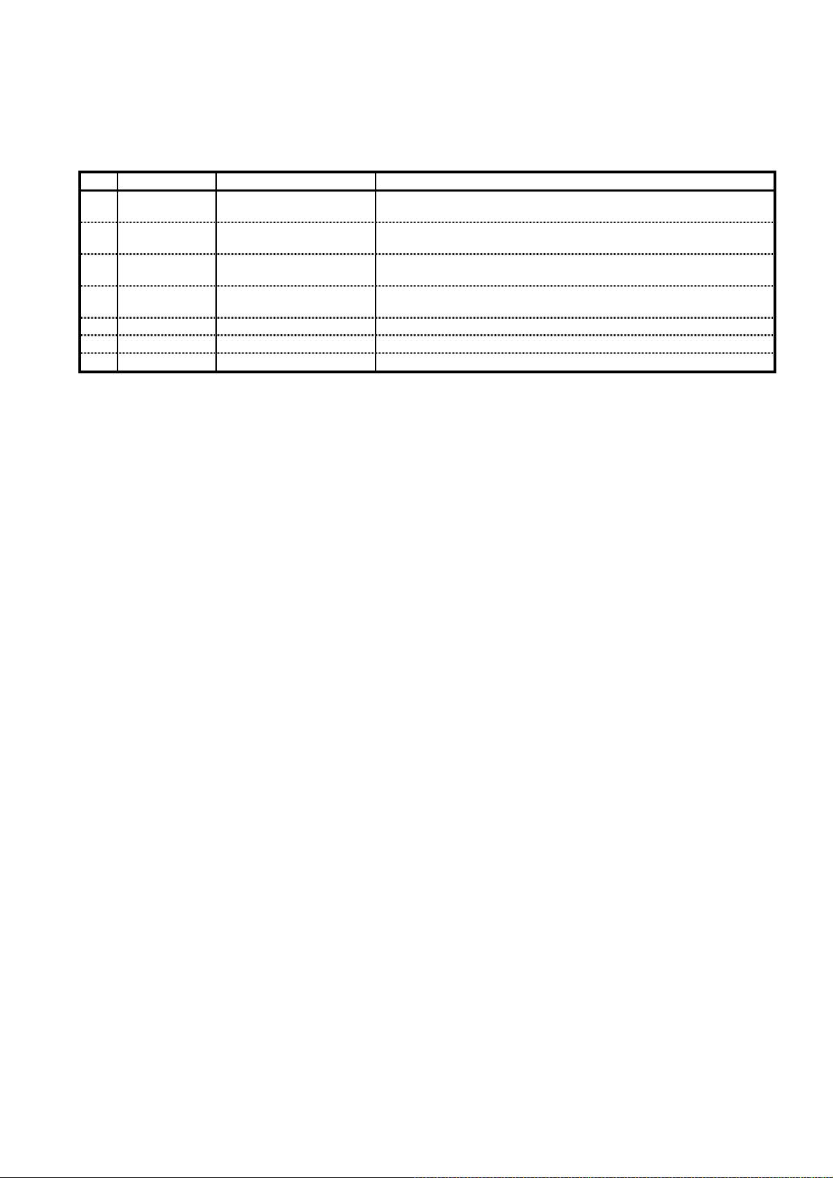
REVISION HISTORY
(
)
(
)
pag
)
(
)
A
gepag
(
)
pag
REV Date Model Reason for Change
00 July 22, 2007
01 May 30, 2008
02 Dec. 19, 2008
03 May 25, 2009
TDP-X2000/2500/3000
common
TDP-X2000/2500/3000
common
TDP-X2000/2500/3000
common
TDP-X2000/2500/3000
common
The first edition.
Changed location name for optical engine.
Modified
dd LCD service kit. Location is E209.
Chan
Correct error : spare part E200 is 'SUB ASSY', not 'PRISM
BLOCK'. Modified
e is 9-2 and 9-4 to 9-12.(Z*** --> E***
e is from 9-2 to 9-12.
e is 9-2.
Page 92

TOSHIBA CORPORATION
1-1, SHIBAURA 1-CHOME, MINATO-KU, TOKYO 105-8001, JAPAN
 Loading...